
 Open Access Article
 This Open Access Article is licensed under a Creative Commons Attribution-Non Commercial 3.0 Unported Licence
Synergy ascension of SnS/MoS2 binary metal sulfides on initial coulombic efficiency and stable capacity for lithium storage†
Kai Pana,
Yanna Sunc,
Xingcun Heb,
Feiyan Laib,
Hongqiang Wangc,
Libo Liangb,
Qingyu Li c,
Xiaohui Zhang*bc and
Hongbing Jia
c,
Xiaohui Zhang*bc and
Hongbing Jia
aSchool of Chemistry and Chemical Engineering, Guangxi Key Laboratory of Petrochemical Resource Processing and Process Intensification Technology, Guangxi University, Nanning 530004, China
bCollege of Materials and Environmental Engineering, Hezhou University, Hezhou 542899, China. E-mail: zxhui017@163.com
cGuangxi Key Laboratory of Low Carbon Energy Materials, Guangxi Normal University, Guilin 541004, China
First published on 12th May 2021
Abstract
Numerous efforts have been devoted to capability improvement and cycling stability in the past decades, and these performances have been significantly enhanced. Low initial coulombic efficiency is still a problem in the metal sulfide-based anode materials. This study developed a strategy to achieve high initial coulombic efficiency and superior capacity retention by interpenetrating binary metal sulfides of SnS and MoS2 in a conductive carbon matrix. The synergy ascension of electrochemical performances for the metal sulfides is attributed to their mutual impeding effects on coarsening of metal grains and the capsule-shaped coating structure embedded in the carbon sheet architecture. The SnS/MoS2/C composite was prepared by a simple NaCl template-assisted ball milling method, and showed excellent electrochemical performances in terms of a high initial coulombic efficiency up to 90.2% and highly stable reversibility with a specific capacity of 515.4 mA h g−1 after 300 cycles at 1.0 A g−1. All of these characteristics suggest that the proposed materials are superior among the previously reported metal sulfide-based anode materials for lithium-ion batteries.
1. Introduction
With the rapid demand of energy, the capacity of commercial graphite materials limits their application as anode materials for a new generation of high energy density lithium-ion batteries (LIBs).1–5 It is necessary to develop new anode materials with high reversible capacity, rate capacity and cycling performance.6–10 The anode performance has a significant effect on the overall energy and power density of the full batteries.11–13 Considerable attention has been paid to metal sulfides, such as MoS2 and Sn-based sulfides,14–16 which have been considered as promising alternative anode materials due to their high theoretical capacity.17–19 MoS2 has attracted considerable attention because of its good chemical stability, high specific capacity as well as simple synthesis. However, volume change caused by phase transformation results in electrode pulverization in the cycling process, and the long-chain lithium polysulfide dissolving and moving to the anode would also lead to capacity loss.20–22 With weaker Sn–S bond and larger interlayer spacing in the layered structure, Sn sulfides are considered to have better kinetical characteristics of lithiation/delithiation compared to Sn oxides.23–26 Studies have shown that a smaller volume change makes SnS more suitable for lithium storage than SnS2,27,28 and it has also attracted interest in research fields of photocatalysis and photodetectors due to its superior physical and chemical properties.29–33 However, the serious pulverization and low electronic conductivity also lead to fast capacity decay.34Numerous effective strategies are introduced to improve the electrochemical performances of metal sulfides, such as reducing the particle size, designing special morphology, and embedding nanoparticles into conductive carbon matrices.35–39 However, as a promising anode material candidate to replace the commercial graphite materials, the enhanced rate and cycling capability still cannot be applied in practice due to another key issue of the low initial coulombic efficiency (ICE). Although some effective efforts have been made to other metal-based anode materials, relatively few studies have reported effective strategies to achieve a high ICE for the metal sulfides.40–44 Recently, Hu et al. have revealed that the coarsening of Sn phases led to a limited conversion back into SnO2 during Li extraction, and the reversible capacity decreased with the increase in the cycling numbers. However, the high-density grain boundary among nanosized SnO2 could suppress the Sn coarsening and enable high ICEs (86.2–95.5%). In view of this, they inhibited the grain coarsening with transition metals to achieve a highly reversible conversion reaction, and all SnO2–metal–graphite composites with different metals exhibited an excellent initial coulombic efficiency.45
Combining the existing theoretical achievements, herein, this study introduces a strategy by interpenetrating binary metal sulfides of SnS and MoS2 together in a conductive carbon sheet architecture via a salt template-assisted ball milling method. Such a unique binary metal sulfide aggregate embedded in a carbon capsule well suppressed the volume change upon cycling and promoted the transferring kinetics of charges. More importantly, the heterogeneous crystal phases with rich boundaries mutually impeded the coarsening of Sn and Mo grains produced in the electrode reaction. Furthermore, Mo catalyzed the decomposition of Li2O due to a much lower energy barrier, resulting in an enhanced reversibility of conversion reactions in the charge process. The synergistic effects achieved a high initial coulombic efficiency with superior retention capacity.
2. Experimental
2.1 Synthesis of SnS/MoS2/C composites
Commercially available metallic Sn (99.9%, 1–3 Micron, Yfnano) powder, SnCl4·5H2O, Na2MoO4·2H2O, NH2CSNH2 and citric acid were used without further purification. SnS/MoS2/C was prepared by the NaCl template method with ball milling. In the first step, Sn powder (0.250 g), SnCl4·5H2O (0.366 g), Na2MoO4·2H2O (0.450 g), NH2CSNH2 (0.846 g), citric acid (3.0 g), NaCl (25.0 g) and ID water (10.0 g) were placed in a 100 mL sealed stainless-steel jar with 30 g of stainless-steel balls. The milling speed was set as 500 rpm for 20 h. Then, the hybrids were dried at 80 °C and calcined at 450 and 750 °C for 2 h, respectively, under Ar atmosphere. NaCl particles were washed away from the black solid power by ID water, and the sample could be obtained after drying at 80 °C overnight. In addition, the reference sample of the SnS/C composite was prepared using 0.250 g of Sn power, 0.366 g of SnCl4·5H2O, 0.146 g NH2CSNH2, 3.0 g citric acid, 25 g NaCl and 10 g ID water under the same conditions, while MoS2/C was synthesized using 0.45 g Na2MoO4·2H2O, 0.70 g NH2CSNH2, 3.0 g citric acid, 25 g NaCl and 10 g H2O.2.2 Materials characterization
General crystal structures of SnS/MoS2/C, SnS/C and MoS2/C were examined by X-ray diffraction (XRD, Rigaku D/max 2500) using Cu Kα radiation from 10°–90° at a scanning rate of 10° min−1. The morphology of the composites was investigated using a field-emission scanning electron microscope (FE-SEM, JEOL 2011), and the morphology in detail was characterized by scanning and high-resolution transmission electron micrographs (TEM and HR-TEM, Philips FEI Quanta 200 FEG). X-ray photoelectron spectroscopy (XPS) was used to analyze the surface of the composites and chemical bonding. The thermal analysis of the carbon content was determined by TGA (TA Apparatus), in which the temperature was raised to 1000 °C at a rate of 5 °C min−1 under air atmosphere.2.3 Electrochemical measurements
The slurry for the electrode was fabricated from the as-prepared composites, Super-P and polymer binder (PVDF) in the weight ratio of 8![[thin space (1/6-em)]](https://www.rsc.org/images/entities/char_2009.gif) :1:1 in a N-methyl-pyrrolidone solution. A Cu foil loaded with the formed slurry was dried at 80 °C overnight in an electric oven. The loading mass was about 0.4 mg cm−2. Then, the electrodes (SnS/MoS2/C, SnS/C and MoS2/C) were assessed by CR2025-type coin cells in an argon-filled glove box, composed of lithium metal as the counter electrode, Celgard (2340) as the separator and 1.0 M LiPF6 in EC/EMC (1:1, vol%) as the electrolyte. All cells were aged for 12 h to ensure that the electrodes were completely soaked in the electrolyte. The electrochemical performances of the cells were assessed by a Land battery testing system (BT2013A). The cyclic voltammetry (CV) and electrochemical impedance spectroscopy (EIS) curves were recorded by an IM6 electrochemical workstation. The CV test was conducted in the voltage range between 0.01 V and 3 V, and the EIS measurements were implemented over the range from 0.01 Hz to 100 kHz.
:1:1 in a N-methyl-pyrrolidone solution. A Cu foil loaded with the formed slurry was dried at 80 °C overnight in an electric oven. The loading mass was about 0.4 mg cm−2. Then, the electrodes (SnS/MoS2/C, SnS/C and MoS2/C) were assessed by CR2025-type coin cells in an argon-filled glove box, composed of lithium metal as the counter electrode, Celgard (2340) as the separator and 1.0 M LiPF6 in EC/EMC (1:1, vol%) as the electrolyte. All cells were aged for 12 h to ensure that the electrodes were completely soaked in the electrolyte. The electrochemical performances of the cells were assessed by a Land battery testing system (BT2013A). The cyclic voltammetry (CV) and electrochemical impedance spectroscopy (EIS) curves were recorded by an IM6 electrochemical workstation. The CV test was conducted in the voltage range between 0.01 V and 3 V, and the EIS measurements were implemented over the range from 0.01 Hz to 100 kHz.
3. Results and discussion
The preparation process of SnS/MoS2/C is shown in Fig. 1. In the first step, metallic Sn, Sn4+ and MoO42+ were thoroughly mixed, and refined in a critic acid solution medium under ball milling. After drying, the SnCl2–Na2MoO4·2H2O–NH2CSNH2–C6H8O7 precursor coated the surface of the NaCl template particles with different sizes. Then, the Sn reacted with Sn4+ to form Sn2+ during a heat treatment under Ar atmosphere, in which the SnS and MoS2 were synthesized, and citric acid was transformed to a carbon film on the NaCl particles. Finally, removing the template crystals left rich interspaces and pores in the architecture supported by the carbon film. For each carbon sheet, the large surface area offered increased electrochemically active sites for the SnS and MoS2 composites.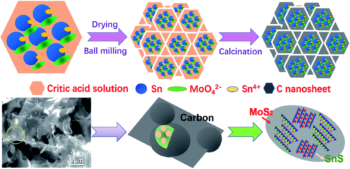 | ||
| Fig. 1 Schematic of the fabrication process and the interpenetrated structure. | ||
The phase structures of the SnS/MoS2/C, SnS/C and MoS2/C composites were analyzed by XRD, as shown in Fig. 2A. The intensive peaks at 25.92°, 27.34°, 31.62° and 45.38° corresponding to the (120), (021), (111) and (002) planes observed in the patterns of the SnS/MoS2/C and SnS/C composites were ascribed to a highly crystalline structure of SnS (JCPDS no. 39-0354). The peaks at 14.40°, 39.52° and 49.82° can be attributed to (002), (103) and (105) planes of the hexagonal MoS2 crystal structure (JCPDS no. 65-1951). The peak at 14.40° was indexed to the (002) plane of MoS2, which indicated the ordered stacking of S–Mo–S layers.46,47 In addition, it is noted that the Sn/C composite contained a small amount of SnO2 and Sn2O3, and the formed oxides could be contributed to the oxidation of Sn during ball milling and heat treatment. There were no peaks attributed to carbon, which may be due to a weak crystal structure caused by the relatively lower annealing temperature. The carbon structure in SnS/MoS2/C was evaluated by Raman spectroscopy, as shown in Fig. S1.† The characteristic peaks of carbon at around 1591.1 and 1348.4 cm−1 correspond to the G and D bands. It is well known that the D band is assigned to the vibrations of carbon atoms with dangling bonds for the in-plane terminations of disordered graphite, and the G band is ascribed to the E2g mode in the basal plane of crystalline graphite. Furthermore, there are another two peaks at around 377.0 and 403.4 cm−1 due to the E2g1 and A1g Raman modes of MoS2, respectively. The composite is a typical carbonaceous material. The contents of C, SnS and MoS2 in the SnS/MoS2/C composite were measured by inductively coupled plasma (ICP) and thermogravimetric analysis (TGA), as shown in Fig. 2B. The results showed that the mass percentage of Sn and Mo were 4.534 and 24.640 wt%, respectively. According to the TGA curves, the composite showed a weight loss of 34.58%. At the range of 100–400 °C, the weight change corresponded to the decomposition of carbon, oxidation of MoS2 to MoO3 and oxidation of SnS to SnO2. As calculated by the result obtained from the ICP and TGA measurements, the contents of MoS2 and SnS were 71.34 and 3.69 wt%, respectively.
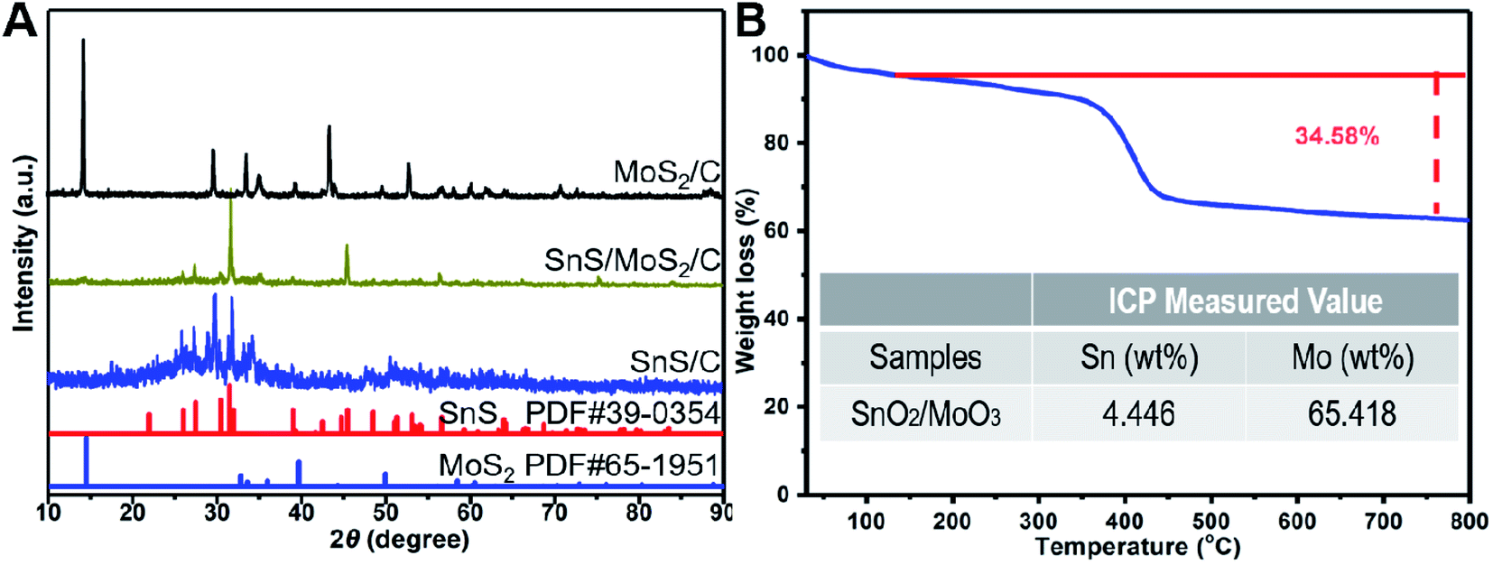 | ||
| Fig. 2 XRD patterns of the SnS/MoS2/C, SnS/C and MoS2/C (A), TGA curve and ICP value of the SnS/MoS2/C sample (B). | ||
The composition of the SnS/MoS2/C sample was explored by the XPS analysis, as shown Fig. 3. Fig. 3A shows a typical survey spectrum of the composite presenting the elements of Sn, Mo and S. Fig. 3B shows the high-resolution XPS spectrum of Sn 3d, and the two main peaks located at 486.9 and 495.3 eV correspond to Sn 3d5/2 and Sn 3d3/2, respectively, which are ascribed to the binding energy of Sn2+ in SnS. The peaks at 235.8 and 232.6 eV are assigned to Mo 3d3/2 and that of Mo 3d5/2 is located at 229.3 and 226.6 eV; the binding energy can be attributed to Mo4+ state. The high resolution of S 2p3/2 at 169.1/168.3 eV and S 2p1/2 at 163.3/162.1 eV are attributed to the binding energy of S in MoS2 and SnS.
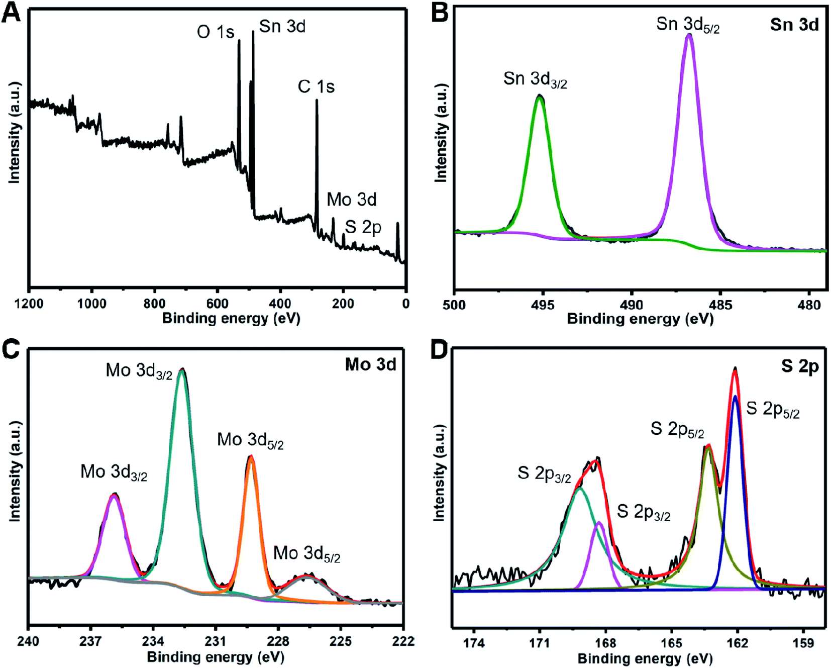 | ||
| Fig. 3 The survey XPS spectra of the SnS/MoS2/C composite (A), the high resolution of Sn 3d (B), Mo 3d (C) and S 2p (D). | ||
The morphology of the SnS/MoS2/C sample is shown in the SEM and TEM images in Fig. 4. Fig. 4A displays that the composite consisted of carbon nanosheets, and these staggered sheets support each other to form a three-dimensional grid. The cross-linked structure is beneficial for the electrode transport in the whole active material. The framework leaves rich pores and exposes large surface to the electrolyte, which promotes the transferring of ions from the electrode material to the electrolyte. From the magnification of the carbon sheets in Fig. 4B, the clear edge suggests an ultrathin sheet-like microstructure. Each particle is embedded in the carbon nanosheet and coated by the carbon layer as a capsule. The full coating protects the active material from the electrolyte and strengthens its structure stability along with cycling as well as improved conductivity. The carbon layer also impedes the particle aggregation of the active materials during heat treatment. By comparison, the SnS/C and MoS2/C samples show a similar composite structure to SnS/MoS2/C (Fig. S2A and B†). The nitrogen adsorption–desorption analysis of the samples (Fig. S3A–C†) exhibits the typical characteristics of mesoporous materials with a BET surface area of 88.01 m2 g−1 for SnS/MoS2/C (Fig. S3C†). The corresponding pore size distribution (Fig. S3D†) indicates that the sample has an abundant mesoporous texture. The TEM image in Fig. 4C shows numerous nanoparticles are dispersedly embedded in the carbon sheets. The high dispersion of the active material is beneficial to capability and weakens the volume effects. To further explore the local crystal phase of the dispersed particles in the HRTEM image, the local grain shows a multi-crystal structure. By measuring the lattice fringes of the crystal phases in Fig. 4D, the fringes correspond to the characteristic lattice plane of SnS and MoS2, respectively. Further characterization by EDS mapping (Fig. S2C†) also reveals the uniform interspersion of Sn, S and Mo elements in the carbon sheets. Therefore, the metal sulfides of SnS and MoS2 were interpenetrated to form partial binary aggregates embedded in carbon capsules. The mutually impeding structure offers rich boundaries and then suppresses the coarsening of Sn and Mo grains. In addition, the Mo formed after lithiation tends to catalyze the decomposition of Li2O, which enhances reversibility of the conversion reactions in the charging process.
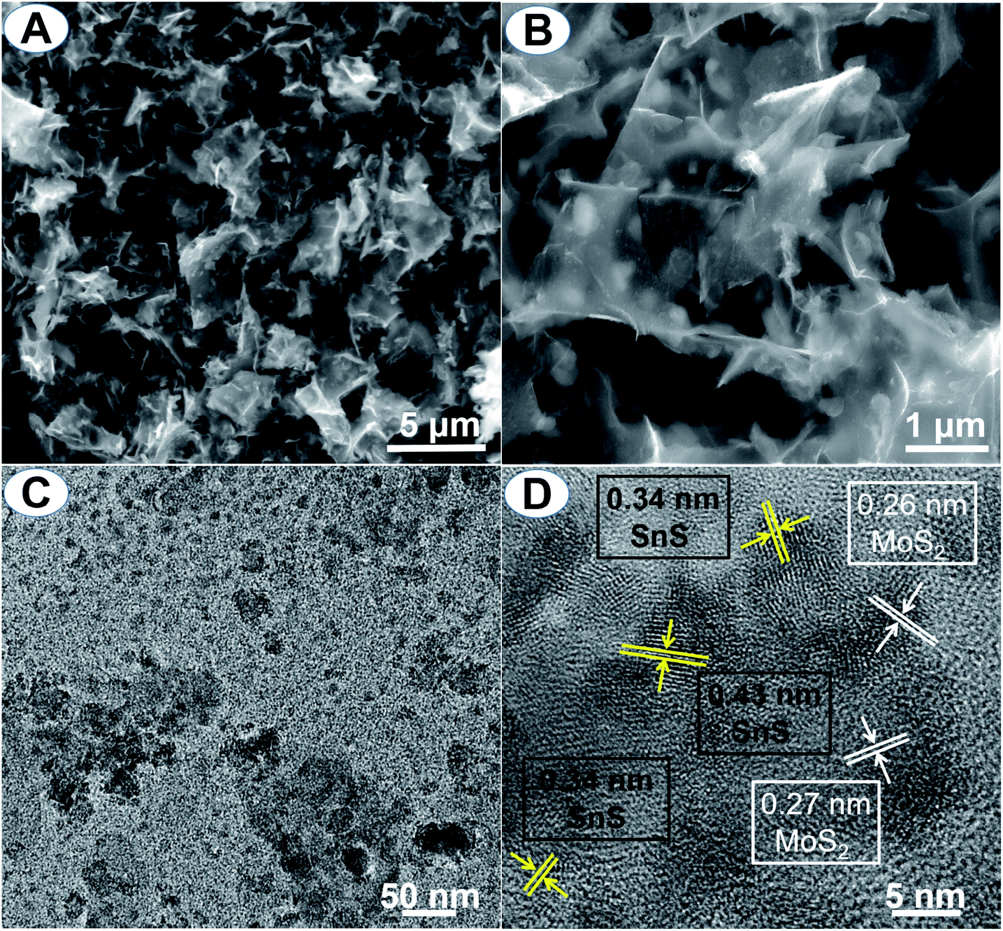 | ||
| Fig. 4 SEM (A and B), TEM (C) and HRTEM (D) images of the SnS/MoS2/C composite. | ||
Fig. 5A shows the discharge–charge profiles of the as-prepared SnS/MoS2/C electrode for the first three cycles at a current density of 0.1 A g−1. For the first cycle, it delivers a discharge capacity of 1249.4 mA h g−1 and obtains a reversible capacity of 1126.3 mA h g−1 with a high initial coulombic efficiency of 90.2%. The value is higher than the most of other recently reported composites, as listed in Table S1.† The following two cycles show a similar capacity with the almost overlapped files. The electrode reactions can be illustrated in the CV curves, as shown in Fig. 5D. In the first anodic scan, the irreversible peaks at about 0.39 and 1.16 V are attributed to the formation of a solid electrolyte interface (SEI) on the material surface. The peaks at 0.1 and 0.8 V are attributed to the formation of LixSn alloys,15 and another peak at 0.21 V corresponds to the conversion reaction of Mo4+ to Mo0, accompanying with the formation of Li2S, and a series of peaks at 1.45 and 2.4 V are assigned to the partial oxidation of Mo to form MoS2, and the extraction of Li+ by the oxidation of Li2S, respectively.48 Moreover the anodic peak at 1.8 V and the cathodic peak at 1.3 V were aroused from the reversibly reaction of LixSnS.13 The overlapped curves of the second and third cycles consistent with the charge/discharge profiles revealed good reversibility. After the 250th cycle, the capacity increased to 790.1 mA h g−1 due to gradually activated reactive sites. However, the MoS2/C sample in Fig. 5B shows an ICE of 84.1%, which is less than that of SnS/MoS2/C. The lost reversible capacity can be attributed to the continuous growth of SEI revealed by the always existing peaks in each anodic scan, as shown in Fig. 5E. Although the composite structure of MoS2 with the carbon matrix is closed to the binary metal sulfides, the single phase tends to produce new crystal boundaries from the collapse of the layered structure by the large volume change. Then, the CV curve of SnS/C did not show severe SEI growing (Fig. 5F), but the lowest ICE of only 64.1% owing to the coarsening of Sn phases led to the limited conversion back into SnO2 during Li extraction, and the reversible capacity decreased with the increase in the cycling numbers (in Fig. 5C).
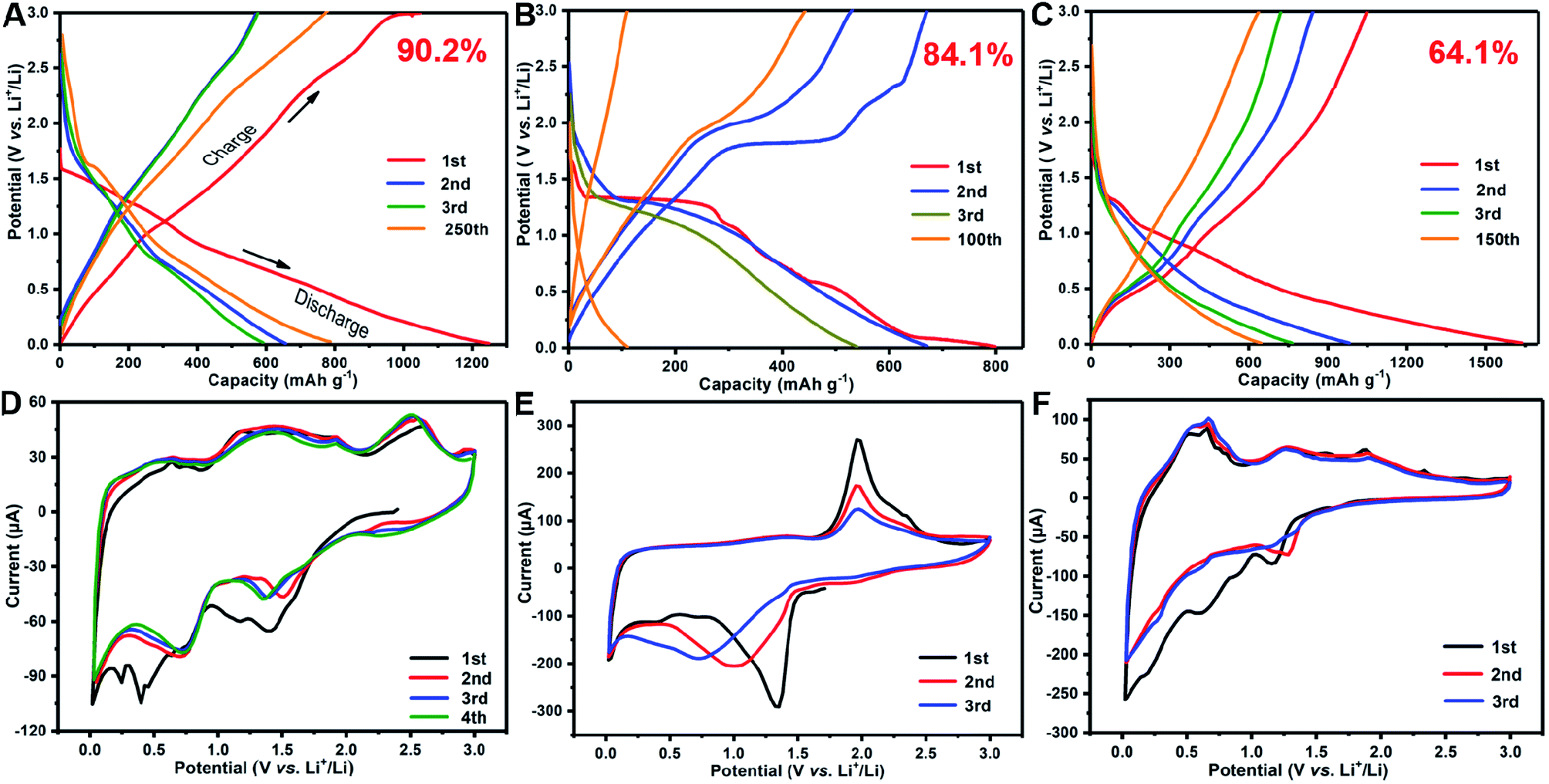 | ||
| Fig. 5 The discharge/charge profiles and CV curves of the SnS/MoS2/C (A, D), MoS2/C (B, E) and SnS/C (C, F) samples. | ||
Fig. 6A displays the rate capability and cycling performances of the SnS/MoS2/C sample as an anode material in a lithium-ion battery at different current densities. Benefiting from the synergistic effects and catalytic action of Mo on the reversibility of conversion reactions, the SnS/MoS2/C composite exhibited the highest capacity among the three samples. The average discharge capacity achieved 651.8 and 238.8 mA h g−1 at 0.2 to 5 A g−1, respectively, as shown in Fig. 6B. As the current density returns to 0.2 A g−1, the reversible capacity comes back to 612.9 mA h g−1, corresponding to a retention of 94%. Compared to SnS/MoS2/C, the MoS2/C sample shows the lowest rate capability. SnS/C showed a comparable capability, but it had only a little capacity at a high current density of 5 A g−1. At a constant current of 0.5 A g−1, the capacity of SnS/MoS2/C remained 726.8 mA h g−1 after 100 cycles on an upward trend due to the increase in the number of active sites during cycling.14 Benefited from its own structure advantage, SnS embedded dispersedly in the carbon framework also showed a good capacity retention of 558.9 mA h g−1. However, MoS2/C only delivered a specific capacity of 115.8 mA h g−1 after 100 cycles at the same current density. The lowest capacity was mainly caused by the rapid decay at the beginning cycles. The ion diffusion coefficients have been calculated from the EIS results to analyze the improved kinetic properties of charge transferring in the electrodes, as shown in Fig. 6C and D.
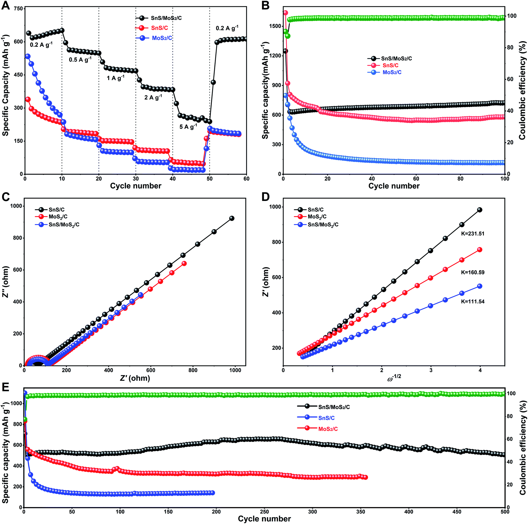 | ||
| Fig. 6 Rate capability (A), short cycling capability at 0.2 A g−1 (B), Nyquist plots (C) and Warburg impedance coefficients (D) after 100 cycles, and long-term cycling performance at 1.0 A g−1 (E) of the SnS/MoS2/C, SnS/C and MoS2/C composites. | ||
DLi+ was calculated from the follow equation:
| DLi+ = R2T2/2A2n4F4C2σ2, |
4. Conclusions
In summary, a binary metal–sulfide of SnS/MoS2 was synthesized via a salt-assisted ball milling process. The heterostructure of metal sulfides interpenetrated in a conductive carbon architecture matrix, and mutually impeded the coarsening of metal grains during cycling. With the synergistic effects, the as-prepared SnS/MoS2/C composite exhibited a high ICE of 90.2% and a superior capacity retention. The improved ICE and facile synthetic strategy are expected to offer a solution for the reversibility issues of metal sulfides as well as other conversion-type anode materials for high energy LIBs.Conflicts of interest
There are no conflicts to declare.Acknowledgements
This work was supported by the National Natural Science Foundation of China (51964013 and 22002025), the Natural Science Foundation of Guangxi (2020GXNSFAA159087), the Special Fund for Guangxi Distinguished Expert, Guangxi Innovation Driven Development Subject (GUIKE AA19182020, GUIKE AA19254004), the Guangxi Technology Base and Talent Subject (GUIKE AD18126001), the Innovation Driven Key Subject of Hezhou (HEKECHUANG CX1907001) and the Basic Ability Improvement Program for Young and Middle-Age Teachers of High School in Guangxi (2019KY0709).References
- X. Li, P. Yan, X. Xiao, J. H. Woo, C. Wang, J. Liu and J.-G. Zhang, Energy Environ. Sci., 2017, 10, 1427 RSC.
- H. Wang, J. Fu, C. Wang, J. Wang, A. Yang, C. Li, Q. Sun, Y. Cui and H. Li, Energy Environ. Sci., 2020, 13, 848 RSC.
- P. Li, J.-Y. Hwang and Y.-K. Sun, ACS Nano, 2019, 13, 2624 CAS.
- X. Li, J. Liu, L. Ouyang, B. Yuan, L. Yang and M. Zhu, Appl. Surf. Sci., 2018, 436, 912 CrossRef CAS.
- Y. Sun, H.-W. Lee, G. Zheng, Z. W. She, J. Sun, Y. Li and Y. Cui, Nano Lett., 2016, 16, 1497 CrossRef CAS PubMed.
- Q. Zhang, H. Chen, L. Luo, B. Zhao, H. Luo, X. Han, J. Wang, C. Wang, Y. Yang and Z. T. M. Liu, Energy Environ. Sci., 2018, 11, 669 RSC.
- W. Li, X. Li, J. Liao, B. Zhao, L. Zhang, L. Huang, G. Liu, Z. Guo and M. Liu, Energy Environ. Sci., 2019, 12, 2286 RSC.
- W. Chen, K. Song, L. Mi, X. Feng, J. Zhang, S. Cui and C. Liu, J. Mater. Chem. A, 2017, 5, 10027 RSC.
- A. K. Thakur, M. S. Ahmed, G. Oh, H. Kang, Y. Jeong, R. Prabakaran, M. P. Vikram, S. W. Sharshir, J. Kim and J.-Y. Hwang, J. Mater. Chem. A, 2021, 9, 2628–2661 RSC.
- L. Lin, X. Xu, C. Chu, M. K. Majeed and J. Yang, Angew. Chem., Int. Ed., 2016, 55, 14063 CrossRef CAS PubMed.
- R. Hu, W. Sun, Y. Chen, M. Zeng and M. Zhu, J. Mater. Chem. A, 2014, 2, 9118 RSC.
- T. Liang, R. Hu, H. Zhang, H. Zhang, H. Wang, Y. Ouyang, J. Liu, L. Yang and M. Zhu, J. Mater. Chem. A, 2018, 6, 7206 RSC.
- D. D. Lecce, R. Verrelli, D. Campanella, V. Marangon and J. Hassoun, ChemSusChem, 2017, 10, 1607 CrossRef PubMed.
- Y. He, L. Xu, C. Li, X. Chen and X. Jiao, Nano Res., 2018, 11, 3555 CrossRef CAS.
- X. W. Guo, X. P. Fang, Y. Sun, L. Y. Shen, Z. X. Wang and L. Q. Chen, J. Power Sources, 2013, 226, 75 CrossRef CAS.
- R. Jia, J. Yue, Q. Xia, J. Xu, X. Zhu, S. Sun, T. Zhai and H. Xia, Energy Storage Mater., 2018, 13, 303 CrossRef.
- C.-Y. Wu, H. Yang, C.-Y. Wu and J.-G. Duh, J. Alloys Compd., 2018, 750, 23 CrossRef CAS.
- J. Shi, Y. Wang, Q. Su, F. Cheng, X. Kong, J. Lin, T. Zhu, S. Liang and A. Pan, Chem. Eng. J., 2018, 353, 606 CrossRef CAS.
- P. Zheng, Z. Dai, Y. Zhang, K. N. Dinh, Y. Zheng, H. S. Fan, J. Yang, R. Dangol, B. Li, Y. Zong, Q. Yan and X. Liu, Nanoscale, 2017, 9, 14820 RSC.
- Y. Huang, Y. Wang, X. Zhang, F. Lai, Y. Sun, Q. Li and H. Wang, Mater. Lett., 2019, 243, 84 CrossRef CAS.
- Q. Pan, F. Zheng, Y. Wu, X. Ou, C. Yang, X. Xiong and M. Liu, J. Mater. Chem. A, 2018, 6, 592 RSC.
- L. Cui, C. Tan, G. Yang, Y. Li, Q. Pan, M. Zhang, Z. Chen, F. Zheng, H. Wang and Q. Li, J. Mater. Chem. A, 2020, 8, 22593 RSC.
- J. Zhu, X. Zhang, C. Zeng, A. Liu and G. Hu, Mater. Lett., 2017, 209, 338 CrossRef CAS.
- X. Hu, J. Chen, G. Zeng, J. Jia, P. Cai, G. Chai and Z. Wen, J. Mater. Chem. A, 2017, 5, 23460 RSC.
- Y. Wang, W. Kang, P. Ma, D. Cao, D. Cao, Z. Kang and D. Sun, Mater. Chem. Front., 2020, 4, 1212 RSC.
- P. Xue, N. Wang, Y. Wang, Y. Zhang, Y. Liu, B. Tang, Z. Bai and S. Dou, Carbon, 2018, 134, 222 CrossRef CAS.
- Y. Zhang, Z. Ma, D. Liu, S. Dou, J. Ma, M. Zhang, Z. Guo, R. Chen and S. Wang, J. Mater. Chem. A, 2017, 5, 512 RSC.
- D. H. Youn, S. K. Stauffer, P. Xiao, H. Park, Y. Nam, A. Dolocan, G. Henkelman, A. Heller and C. B. Mullins, ACS Nano, 2016, 10, 10778 CrossRef CAS PubMed.
- J. Liu, M. Gu, L. Ouyang, H. Wang, L. Yang and M. Zhu, ACS Appl. Mater. Interfaces, 2016, 8, 8502 CrossRef CAS PubMed.
- C. Li, B. Wang, D. Chen, L.-Y. Gan, Y. Feng, Y. Zhang, Y. Yang, H. Geng, X. Rui and Y. Yu, ACS Nano, 2020, 14, 531 CrossRef CAS PubMed.
- Y. Cheng, Z. Wang, L. Chang, S. Wang, Q. Sun, Z. Yi and L. Wang, ACS Appl. Mater. Interfaces, 2020, 12, 25786 CrossRef CAS PubMed.
- J. Cai, Z. Li and P. K. Shen, ACS Appl. Mater. Interfaces, 2012, 4, 4093 CrossRef CAS PubMed.
- S. Zhang, H. Ying, P. Huang, J. Wang, Z. Zhang, T. Yang and W. Han, ACS Nano, 2020, 14, 17665 CrossRef CAS PubMed.
- X. Xiong, C. Yang, G. Wang, Y. Lin, X. Ou, J.-H. Wang, B. Zhao, M. Liu, Z. Lin and K. Huang, Energy Environ. Sci., 2017, 10, 1757–1763 RSC.
- H. Fang, Y. Chen, M. Wen, Q. Wu and Q. Zhu, Nano Res., 2017, 10, 3929 CrossRef CAS.
- Q. Pan, F. Zheng, Y. Wu, X. Ou, C. Yang, X. Xiong and M. Liu, J. Mater. Chem. A, 2018, 6, 592 RSC.
- S. Chen, K. Xing, J. Wen, M. Wen, Q. Wu and Y. Cui, J. Mater. Chem. A, 2018, 6, 7631 RSC.
- H. Wang, Q. Pan, Q. Wu, X. Zhang, Y. Huang, Q. Li and X. Sun, J. Mater. Chem. A, 2017, 5, 4576 RSC.
- Q. Pan, Y. Huang, H. Wang, G. Yang, L. Wang, J. Chen, Y. Zan and Q. Li, Electrochim. Acta, 2016, 197, 50 CrossRef CAS.
- C. Zhang, Z. Lin, Z. Yang, Z. D. Xiao, P. Hu, H. Xu, Y. Duan, S. Pang, L. Gu and G. Cui, Chem. Mater., 2015, 27, 2189–2194 CrossRef CAS.
- Y. Wang, S. Luo, M. Chen and L. Wu, Adv. Funct. Mater., 2020, 30, 2000373 CrossRef CAS.
- L. Zhang, J. Song, Y. Liu, X. Yuan and S. Guo, J. Power Sources, 2018, 379, 68 CrossRef CAS.
- R. Hu, Y. Ouyang, T. Liang, H. Wang, J. Liu, J. Chen, C. Yang, L. Yang and M. Zhu, Adv. Mater., 2017, 29, 1605006 CrossRef PubMed.
- Z. Huang, S. Ding, P. Li, C. Chen and M. Zhang, Nanotechnology, 2020, 32, 025401 CrossRef PubMed.
- R. Hu, Y. Ouyang, T. Liang, X. Tang, B. Yuan, J. Liu, L. Zhang, L. Yang and M. Zhu, Energy Environ. Sci., 2017, 10, 2017 RSC.
- Y. Chao, R. Jalili, Y. Ge, C. Wang, T. Zheng, K. Shu and G. G. Wallace, Adv. Funct. Mater., 2017, 27, 1700234 CrossRef.
- L. Zhang and X. W. Lou, Chem.–Eur. J., 2014, 20, 5219 CrossRef CAS PubMed.
- Y. Jiao, A. Mukhopadhyay, Y. Ma, L. Yang, A. M. Hafez and H. Zhu, Adv. Energy Mater., 2018, 8, 1702779 CrossRef.
Footnote |
| † Electronic supplementary information (ESI) available. See DOI: 10.1039/d1ra01267c |
| This journal is © The Royal Society of Chemistry 2021 |