 Open Access Article
A carbon membrane-mediated CdSe and TiO2 nanofiber film for enhanced photoelectrochemical degradation of methylene blue†
Xinye Zhanga,
Xueyue Zhanga,
Keting Fenga,
Xiaoyun Hu b,
Jun Fan
 a and
Enzhou Liu
 *a
*a
aSchool of Chemical Engineering, Xi'an Key Laboratory of Special Energy Materials, Northwest University, Xi'an, 710069, P. R. China. E-mail: ok.208@163.com
bSchool of Physics, Northwest University, Xi'an, 710069, P. R. China
First published on 23rd March 2021
Abstract
In this study, a carbon membrane-mediated CdSe and TiO2 ternary film (CdSe/C/TiO2) was prepared to degrade methylene blue (MB). Carbon membrane and CdSe were introduced to the surface of a TiO2 nanofiber film via an in situ hydrothermal deposition process successively. The investigation shows that the carbon membrane not only provides a charge transfer channel to promote the transfer of electron from the conduction band of CdSe to that of TiO2, but also improves the poor conduct between the TiO2 film and electrolyte. The synergies between the carbon membrane and CdSe can make the ternary system harvest more visible light energy and facilitate the charge transfer property of TiO2. The current density of CdSe/C/TiO2 was about 9 folds higher compared with that of pure TiO2 under UV and visible light irradiations. This ternary hybrid exhibits a superior activity during the photoelectrochemical (PEC) degradation of MB, and 92.43% can be removed after 120 min irradiation, which is improved by 21.14% than that of TiO2.
1. Introduction
Waste discharge from chemical industries is threatening to the health of human beings.1 The waste-related environmental problems need to be solved urgently.2,3 In the past few years, numerous traditional ways have been employed in disposing water pollution including absorption, photocatalysis, electrocatalysis, and microbiological degradation.4–8 However, the above-mentioned solutions suffer from high cost, low efficiency, secondary pollution, and so on.9–11 At present, compared with photocatalysis and electrocatalysis, photoelectrocatalytic degradation has received considerable attention owing to its low cost, sustainability and high efficiency, which can decompose the organic pollutants into H2O and CO2 completely.12–17 Until now, numerous photoelectrocatalysts have been developed for the photoelectrochemical (PEC) processes, such as TiO2, ZnO, and MnO2.18–20 Among them, TiO2 has been widely investigated for its physical and chemical stability, non-toxicity and available properties.21,22However, there are still limitations for the practical applications of TiO2: (1) its inherent band gap of 3.0–3.2 eV leads to poor visible light capture ability; (2) fast recombination of the charge carriers results in an inefficient photoexcitation process; (3) the powder form of TiO2 makes it hard to reuse for the separation problems.23,24 In the last few decades, various strategies have been employed to improve the activity of TiO2. For example, metal doping (Au, Ag, Pt, Ni, etc.),25–28 coupling with narrow-gap semiconductors (ZnSe, CdSe, CdS, etc.),29–33 and introducing carbon-based materials.34
Investigations demonstrate that the combination of TiO2 with narrow band gap semiconductors to form heterojunctions is an effective strategy to achieve wider range of light absorption and faster separation of charge carrier simultaneously.35–37 Recently, CdSe with a suitable conduction band position and an ideal band gap (1.7 eV) has been widely used for the sensitization of TiO2. The hybrids can be applied in H2 evolution, CO2 reduction and pollutants degradation.38–41 Xu et al. used CdSe/TiO2 powder to degrade MB, and the removal efficiency was 90.5% after 5 h of irradiation.42 Although the above-mentioned heterojunction can promote charge transfer and improve the light harvesting ability of TiO2, the question that remains is CdSe, a small-diameter-particle, randomly combined with TiO2 cannot solve the problem of poor contact between the TiO2 photoanode and the electrolyte, which is proved to be the key point in improving the PEC efficiency.
Carbon materials (graphene, carbon quantum dots, carbon nanofibers, carbon membrane, etc.) have been widely employed to improve the PEC activity of TiO2.43–47 They not only provide a carrier transport channel to accelerate the carrier transfer but also promote the contact properties between TiO2 and electrolyte.48–50 Gao et al. used γ-graphene to enhance the activity of TiO2 nanotube arrays, and the degradation rate of rhodamine B was increased slightly (1.35 times).51 Liu et al. used carbon quantum dots to facilitate the charge transfer between Cd0.5Zn0.5S and TiO2 nanorod film (CZS/C/TiO2 NRF), the photocurrent density was boosted to 8.19 μA cm−2.52 It is confirmed that carbon materials can greatly improve the PEC activity of TiO2 with excellent PEC performance. However, graphene and carbon nanofibers are difficult to prepare, and carbon quantum dot is hard to separate during the preparation and it easily falls off from the substrate. Recently, Zhang et al. used a simple strategy to introduce a carbon membrane on TiO2 nanotube arrays, and this nanofilm can be easily separated and reused for its excellent stability.53 Even so, there are few researches on the use of carbon membranes in PEC degradation.
In this study, a carbon membrane-bridged CdSe and TiO2 ternary film (CdSe/C/TiO2) was prepared via an in situ hydrothermal deposition process successively. We found that the carbon membrane, as a carrier-transfer-channel, can accelerate the electron migration from the conduction band of CdSe to that of TiO2, and improve the poor contact between TiO2 and electrolyte. The current density of CdSe/C/TiO2 (45.36 μA cm−2) was about 9 times compared with that of pure TiO2 (5.42 μA cm−2) under UV and visible light irradiations, and the performance of the ternary CdSe/C/TiO2 film was tested in the photoelectrocatalytic degradation of MB. The results reveal that the degradation efficiency of CdSe/C/TiO2 (92.43%) significantly increased by 21.14% than that of the pure TiO2. Finally, the PEC mechanism over the CdSe/C/TiO2 nanofiber film was proposed based on the PEC analyses and free radical capture experiments.
2. Experimental processes
2.1 Preparation of the CdSe/C/TiO2 nanofiber film
A TiO2 nanofiber film was obtained via a hydrothermal process, followed by acidification and annealing treatments. As shown in Scheme 1, a Ti sheet (20 × 40 × 0.2 mm) was first chemically polished using a mixed acid solution consisting of HF, HNO3 and H2O to remove surface impurities. Subsequently, 2 g NaOH was dissolved in 25 mL of ethylene glycol and 25 mL of deionized water, and stirred for 30 min. Then, the polished Ti sheet was put into a Teflon-lined stainless steel vessel with the above solution together, sealed and heated at 180 °C for 24 h. Hereafter, the sample was acidified in HCl (0.25% wt) for 24 h. Finally, the TiO2 nanofiber film was obtained after calcination at 350 °C for 2 h at a heating rate of 5 °C min−1.A carbon membrane was coated on the TiO2 nanofilm via a simple hydrothermal process. 0.432 g glucose and 0.042 g ascorbic acid were added into 50 mL of H2O under stirring. Subsequently, the TiO2 nanofiber film and above mixture were sealed in a Teflon-lined stainless steel vessel, and heated at 80 °C for 12 h to obtain the C/TiO2 nanofiber film.
The CdSe/C/TiO2 ternary film was prepared via a hydrothermal process too. 0.0237 g Se powder was dissolved in 40 mL of diethylenetriamine (solution A), and then CdCl2 was dissolved in 10 mL of H2O (solution B). Subsequently, solution A and solution B were mixed under stirring and then transferred into a Teflon-lined stainless steel vessel. Further, the above C/TiO2 nanofiber film was immersed into this mixture, sealed and maintained at 160 °C for 12 h. After cooling naturally, the film was washed using deionized water and ethanol, and dried at room temperature to obtain the CdSe/C/TiO2 ternary nanofiber film.
2.2 Characterization
The ESI† provide details of characterization, PEC measurements and PEC performance test.3. Results and discussion
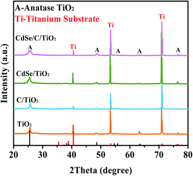
Fig. 1 presents the X-ray diffraction (XRD) patterns of the sample. The characteristic diffraction peaks of anatase TiO2 are observed in all the samples. Peaks at 25.69°, 48.79°, 54.77°, 55.94°, 63.14° and 76.37° belong to the crystal surfaces of (101), (200), (105), (211), (213) and (215) of anatase TiO2, respectively (JCPDS no. 75-1537).54 Moreover, the peaks located at 40.17°, 53.00° and 70.66° are assigned to the Ti sheet substrate (JCPDS no. 44-1294). Besides, the signals of the carbon membrane and CdSe are not observed due to the low content and poor crystallinity of CdSe and the amorphous nature of carbon, but they can be observed by EDS and XPS.46,54As shown in Fig. 2A–C, the TiO2 film is composed of a large number of nanofibers intertwined to form a stable structure (nanofiber film), which is conducive to the light scattering and harvesting abilities of the TiO2 film. This network structure becomes rougher when the carbon membrane is loaded (Fig. 2B). As shown in Fig. 2C, the CdSe nanoparticles are obviously supported on the C/TiO2. Notably, the film-shape is easier for cyclic utilization than the powder form of TiO2, which is beneficial for the practical application. According to the EDS (Fig. 2D) and elemental mapping (Fig. 2E–I), it is obvious that there are signals of Ti, O, C, Cd and Se. It is confirmed that the carbon membrane and CdSe co-exist on the surface of the TiO2 film with good dispersion.
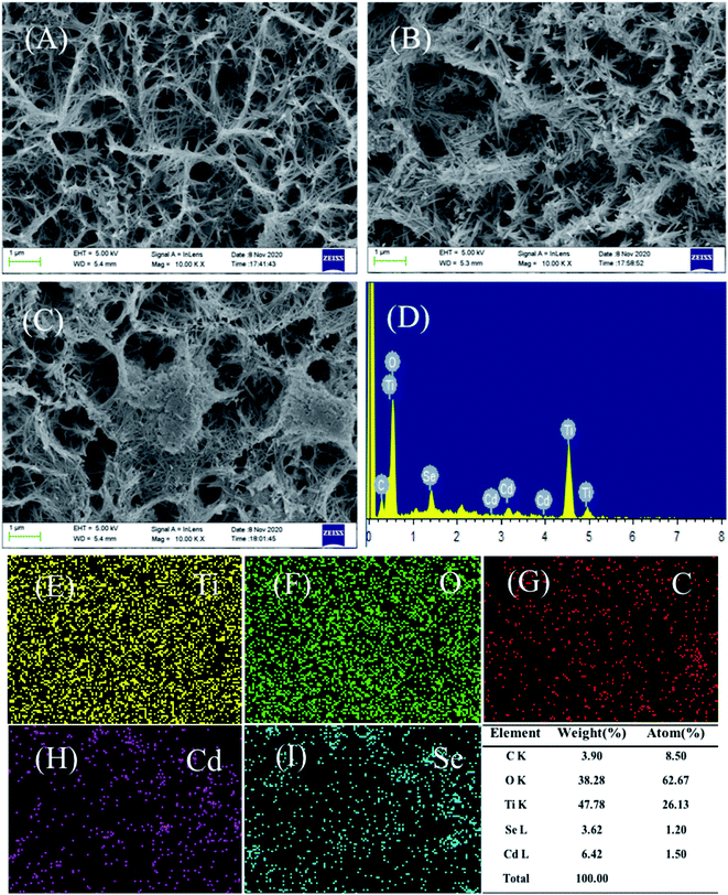 | ||
| Fig. 2 (A–C) SEM images of all samples: (A) pure TiO2, (B) C/TiO2, and (C) CdSe/C/TiO2; (D) EDS of CdSe/C/TiO2; (E–I) elemental mapping images for Ti, O, C, Cd and Se. | ||
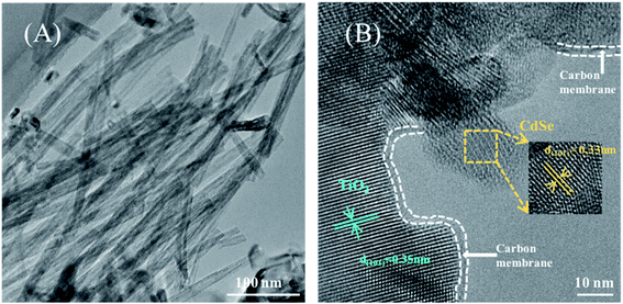
The microstructure of the CdSe/C/TiO2 nanofiber film is also investigated by TEM. As shown in Fig. 3A, nanofibers of TiO2 with a reticular structure can be clearly observed, and it is well preserved after the deposition of the carbon membrane and CdSe. The HRTEM image in Fig. 3B clearly reveals that the inter-planar spacing of the crystal lattice is 0.35 nm, which is consistent with the (101) plane of anatase TiO2. Besides, the carbon membrane is loaded on the surface TiO2, and the thickness of the carbon membrane is about 2–3 nm. It is clearly seen that the CdSe particles are supported outside the carbon membrane, and the spacing of 0.35 nm belongs to the (101) plane of CdSe. Above TEM analysis further confirms the co-existence of carbon and CdSe on the surface of the TiO2 nanofilm.
X-ray photoelectron spectroscopy (XPS) is an important technique to confirm the elements and their states over the surface of the materials.55 As shown in the survey spectrum (Fig. 4A), the signals of Ti, O, C, Cd and Se can be detected. The corresponding high resolution spectra are shown in Fig. 4B–F. The spectrum of C 1s can be fitted into three peaks at 284.6, 286.1 and 288.1 eV in Fig. 4B, and they are attributed to the C–C, C–O and C![[double bond, length as m-dash]](https://www.rsc.org/images/entities/char_e001.gif) O, respectively.56 As shown in Fig. 4C, the peaks at 458.3 and 464.0 eV correspond to Ti 2p3/2 and Ti 2p1/2, respectively.57 The three peaks at around 529.6, 530.1 and 530.7 eV are ascribed to Ti–O, C
O, respectively.56 As shown in Fig. 4C, the peaks at 458.3 and 464.0 eV correspond to Ti 2p3/2 and Ti 2p1/2, respectively.57 The three peaks at around 529.6, 530.1 and 530.7 eV are ascribed to Ti–O, C![[double bond, length as m-dash]](https://www.rsc.org/images/entities/char_e001.gif) O and C–OH in the spectrum of O 1s (Fig. 4D), respectively, revealing the presence of carbon in this composite.58 Moreover, the double peaks at 404.6 and 411.3 eV in Fig. 4E are designated to 3d5/2 and 3d3/2 of Cd2+.59 The peak at 50.7 eV in Fig. 4F indicates the existence of Se2−.60 Above proofs further confirm that the carbon membrane and CdSe co-exist on the surface of the TiO2 nanofiber film.
O and C–OH in the spectrum of O 1s (Fig. 4D), respectively, revealing the presence of carbon in this composite.58 Moreover, the double peaks at 404.6 and 411.3 eV in Fig. 4E are designated to 3d5/2 and 3d3/2 of Cd2+.59 The peak at 50.7 eV in Fig. 4F indicates the existence of Se2−.60 Above proofs further confirm that the carbon membrane and CdSe co-exist on the surface of the TiO2 nanofiber film.
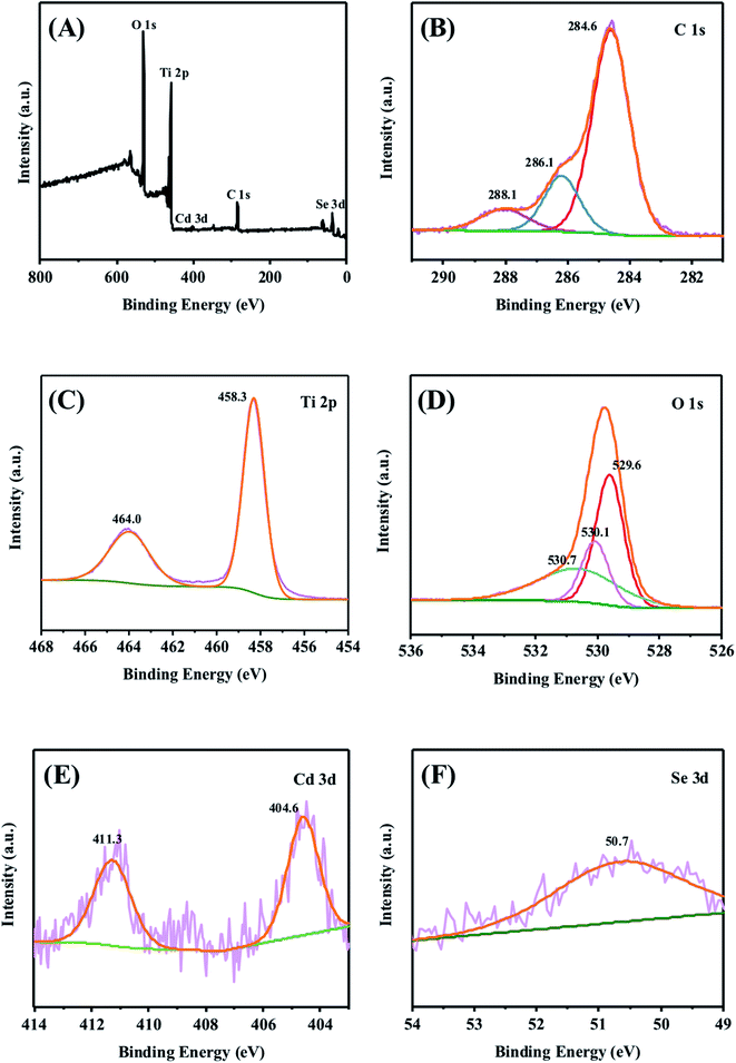 | ||
| Fig. 4 (A) XPS survey spectrum of the CdSe/C/TiO2 ternary nanofiber film, and high resolution spectra of (B) C 1s, (C) Ti 2p, (D) O 1s, (E) Cd 3d and (F) Se 3d. | ||
Fig. 5A shows the UV-Vis absorption properties of the samples. All the samples exhibit absorption at the edge of 386 nm, corresponding to a band gap energy of 3.2 eV, which results from the inherent absorption of anatase TiO2.38 This interlacing network structure of TiO2 leads to the irregular scattering effects of incident light, enhancing the light harvesting ability (Fig. 2A). After introducing CdSe particles, the absorption of CdSe/TiO2 in the visible light range clearly got enhanced owing to the narrower band gap of CdSe. Carbon membrane can also capture visible light and further enhance the absorption capacity of the samples because of its unique optical properties.61 These results indicate that the combination of carbon membrane and CdSe endows the ternary composite (CdSe/C/TiO2) with excellent visible light absorption ability.
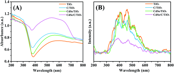 | ||
| Fig. 5 (A) UV-Vis diffuse reflectance spectra (DRS) of all samples and (B) PL spectra with the excitation wavelength of 220 nm. | ||
The photoluminescence (PL) spectra were obtained to illustrate the charge recombination efficiency, as shown in Fig. 5B. Under excitation at 220 nm, they all share same emission shapes around 400 and 465 nm. The emission intensity of C/TiO2 and CdSe/TiO2 are lower than that of the TiO2 nanofiber film. After introducing the carbon membrane and CdSe, the PL emission intensity of CdSe/C/TiO2 obviously decreased, suggesting that the recombination of electrons and holes is inhibited in this CdSe/C/TiO2 heterojunction.
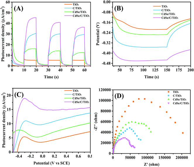
Fig. 6A presents the photocurrent density of the samples. The photocurrent density elevates quickly after the light illumination, and then decreases rapidly to 0 μA cm−2 under dark conditions, indicating that all the electrodes have very sensitive optical response. C/TiO2 (29.52 μA cm−2) and CdSe/TiO2 (16.16 μA cm−2) both exhibit higher photocurrent density than TiO2 (5.42 μA cm−2). In addition, the current density of the CdSe/C/TiO2 film is 45.36 μA cm−2, which is 9 folds enhancement compared to that of TiO2, which indicates that more electrons can be effectively transferred from the CdSe/C/TiO2 photoanode to the Pt counter electrode, which accelerates the separation of electrons and holes.
As displayed in Fig. 6B, open-circuit potential (Voc) is used to further reveal its photoelectric property. When the Xe lamp is switched on, the photoelectrodes produce high photovoltages with better photosensitivity and stability, which benefits from the balance of accumulation and recombination of the charge carriers on the surface of the catalyst. Compared with pure TiO2, all the samples exhibit higher electric potential than TiO2. Among them, the ternary composite CdSe/C/TiO2 exhibits the highest Voc, indicating that the charge separation efficiency is the best and more electrons can be accumulated. In addition, the linear sweep voltammetric curves (LSV) is recorded to determine the PEC property, as shown in Fig. 6C. CdSe/C/TiO2 shows better PEC performance, achieving the highest current density than the others at an overpotential of 0.5 V. The synergistic effects of the carbon membrane and CdSe leads to an obvious enhancement of its PEC behavior. The result is consistent with the above photocurrent density and Voc results.
To further understand the generation and accumulation properties of the carriers for all the samples, electrochemical impedance spectroscopy (EIS) was performed on different electrodes. The diameter of the semicircle in the Nyquist diagram expresses the resistance during charge transfer processes.62 Clearly, as shown in Fig. 6D, the resistance of TiO2 is the largest, and the diameter of each composite is smaller than that of their single component. In particular, the diameter of CdSe/C/TiO2 is the smallest, indicating that the electron transfer resistance is lowest and the charge transfer in the electrode is the fastest; therefore, the ternary composite possesses excellent PEC properties. In summary, the unique electron transfer property of the carbon membrane, as well as the synergistic effect with CdSe, can effectively inhibit the charge recombination and achieve higher PEC performance.
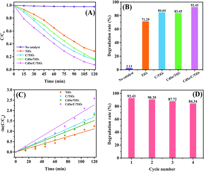
To further demonstrate the PEC property, the degradation efficiency of MB is illustrated in Fig. 7A and B, and the raw data for MB degradation is shown in Fig. S1.† Clearly, CdSe/C/TiO2 can significantly achieve the removal of MB. Without the catalyst, only 2.13% of MB can be degraded after 120 min of light irradiation, indicating that MB can hardly induce self-degradation. Pure TiO2 can only decompose 71.29% of MB, while the degradation efficiency of MB can reach 84.64%, 83.45% and 92.43% over C, CdSe, CdSe and C-modified samples, respectively. Therefore, the ternary CdSe/C/TiO2 exhibits the best PEC activity with an improvement of 21.14% compared with pure TiO2. In addition, the degradation kinetics of MB can be described as a pseudo-first-order reaction using the following formula:
| ln(C/C0) = −kt | (1) |
As shown in Fig. 7C, the kinetic rate constants for TiO2, C/TiO2, CdSe/TiO2 and CdSe/C/TiO2 electrode are approximately 9.33 × 10⁻³, 14.18 × 10⁻³, 12.67 × 10⁻³ and 18.93 × 10⁻³ min−1, and marked as k1, k2, k3 and k4, respectively. The order of rate constants is k4 > k2 > k3 > k1, indicating that the CdSe/C/TiO2 ternary composite has a faster degradation rate than the others. Furthermore, stability is also a key indicator of industrial applications of the catalyst. As shown in Fig. 7D, when the catalyst is cycled four times, it is found that there is no significant decrease, indicating that the catalyst is stable.
Furthermore, PEC experiment was performed using different scavengers to reveal the role of the active substances. Here, 1,4-benzoquinone (BQ), ammonium oxalate (AO) and isopropanol (IPA) were used as the trapping agents for the superoxide radical scavenger (˙O2−), hole scavenger (h+), and hydroxyl radical scavenger (˙OH), respectively.64 Fig. 8 shows the results of the trapping experiment. It is clear that the degradation rate of CdSe/C/TiO2 is 92.43% in the absence of the capture agent. When BQ and AO are added, the degradation rates decrease to 69.36% and 73.11%, respectively, indicating that ˙O2− and h+ are the major active substances during the MB degradation. When IPA is added, the degradation rate is also affected, but the effects of ˙OH is relatively low.
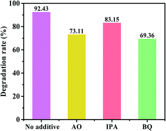 | ||
| Fig. 8 The photoelectrocatalysis degradation of MB by CdSe/C/TiO2 after the addition of h+, ˙OH and ˙O2− scavengers. | ||
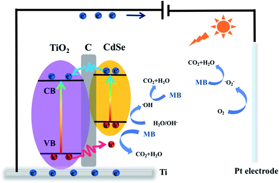
According to the above-mentioned conclusions, a tentative mechanism is proposed to understand the degradation process. As shown in Fig. 9, electrons can be transferred from the valence band (VB) to the conduction band (CB) in TiO2 and CdSe under light excitation. Holes from the VB of TiO2 migrate to the VB of CdSe through the carbon membrane because of the potential difference, and then electrons transfer from the CB of CdSe to the CB of TiO2 through the carbon membrane. Therefore, the carbon membrane plays a vital role as a carrier-transfer-channel between TiO2 and CdSe. Subsequently, electrons will transport into the metal Ti through the TiO2 nanofiber film, and continuously migrate to the Pt cathode under the bias potential. ˙O2− is generated from the reaction between the electron and the oxygen adsorbed on the surface of the cathode, and it can participate in the MB degradation process. Moreover, the carbon membrane can improve the interfacial contact between the semiconductor and the electrolyte, which promotes the contact between the holes and the organic pollutants during the degradation reaction, resulting in more h+ to degrade MB.65 This mechanism can be expressed by:
| CdSe/C/TiO2 → CdSe (h+)/C/TiO2 (e−) | (2) |
| TiO2 (e−) + Pt → TiO2 + Pt (e−) | (3) |
| Pt (e−) + O2 → ˙O2− + Pt | (4) |
| h+ + OH−/H2O → ˙OH | (5) |
| ˙O2−/h+/˙OH + MB → CO2 + H2O | (6) |
4. Conclusion
In summary, a CdSe/C/TiO2 nanofiber film was developed for the photoelectrocatalytic degradation of MB. The CdSe/C/TiO2 ternary composite exhibits a better PEC performance compared with its binary hybrids. The current density of the CdSe/C/TiO2 nanofilm is about 9 times higher than that of pure TiO2 under UV and visible light irradiations. Voc and EIS results show that the CdSe/C/TiO2 nanofiber film has better charge transfer capacity because the carbon membrane not only can greatly accelerate the carrier transfer as a carrier-transport-channel but can also improve the problem of the poor contact between the semiconductor and the electrolyte. The photoelectrocatalytic degradation of MB by CdSe/C/TiO2 is significantly increased by about 21.14% than that of pure TiO2. Therefore, the synergistic effects of the carbon membrane and CdSe endows the ternary composite sample CdSe/C/TiO2 with excellent PEC performance. This study presents a great contribution to the preparation of highly efficient PEC degradation materials.Author contributions
Xinye Zhang: writing, methodology, investigation, original draft. Xueyue Zhang: data curation, review & editing. Keting Feng: formal analysis, review & editing. Xiaoyun Hu: supervision, review & editing. Jun Fan: review & editing. Enzhou Liu: project administration, funding acquisition.Conflicts of interest
There are no conflicts to declare.Acknowledgements
This work was supported by the National Natural Science Foundation of China (No. 21676213, 11974276 and 22078261), Natural Science Basic Research Program of Shaanxi (No. 2020JM-422), China Postdoctoral Science Foundation (No. 2016M600809).References
- H. Zhou, Y. Qu, T. Zeid and X. Duan, Energy Environ. Sci., 2012, 5, 6732–6743 RSC
.
- C. Li, T. Lou, X. Yan, Y. Long, G. Cui and X. Wang, Int. J. Biol. Macromol., 2018, 106, 768–774 CrossRef CAS PubMed
.
- T. Robinson, G. McMullan, R. Marchant and P. Nigam, Bioresour. Technol., 2001, 77, 247–255 CrossRef CAS PubMed
.
- U. Habiba, T. A. Siddique, T. C. Joo, A. Salleh, B. C. Ang and A. M. Afifi, Carbohydr. Polym., 2017, 157, 1568–1576 CrossRef CAS PubMed
.
- H. She, H. Zhou, L. Li, L. Wang, J. Huang and Q. Wang, ACS Sustainable Chem. Eng., 2018, 6, 11939–11948 CrossRef CAS
.
- M. Zhou, Q. Dai, L. Lei, C. Ma and D. Wang, Environ. Sci. Technol., 2005, 39, 363–370 CrossRef CAS PubMed
.
- W. Przystaś, E. Zabłocka-Godlewska and E. Grabińska-Sota, Water, Air, Soil Pollut., 2012, 223, 1581–1592 CrossRef PubMed
.
- A. Xu, W. Tu, S. Shen, Z. Lin, N. Gao and W. Zhong, Appl. Surf. Sci., 2020, 528, 146949 CrossRef CAS
.
- H. Dong, X. Guan, D. Wang, C. Li, X. Yang and X. Dou, Chemosphere, 2011, 85, 1115–1121 CrossRef CAS PubMed
.
- I. Oller, S. Malato and J. A. Sánchez-Pérez, Sci. Total Environ., 2011, 409, 4141–4166 CrossRef CAS PubMed
.
- Y. Zhou, L. Tang, G. Zeng, J. Chen, Y. Cai, Y. Zhang, G. Yang, Y. Liu, C. Zhang and W. Tang, Biosens. Bioelectron., 2014, 61, 519–525 CrossRef CAS PubMed
.
- W. Zhong, Z. Wang, N. Gao, L. Huang, Z. Lin, Y. Liu, F. Meng, J. Deng, S. Jin, Q. Zhang and L. Gu, Angew. Chem., Int. Ed., 2020, 59, 22743–22748 CrossRef CAS PubMed
.
- M. A. Ahmed, M. F. Abdel-Messih and E. H. Ismail, J. Mater. Sci.: Mater. Electron., 2019, 30, 17527–17539 CrossRef CAS
.
- D. Cao, Y. Wang, M. Qiao and X. Zhao, J. Catal., 2018, 360, 240–249 CrossRef CAS
.
- K. Wang, Y. Zhang, L. Liu, N. Lu and Z. Zhang, J. Mater. Sci., 2019, 54, 8426–8435 CrossRef CAS
.
- M. Shaban, A. M. Ahmed, N. Shehata, M. A. Betiha and A. M. Rabie, J. Colloid Interface Sci., 2019, 555, 31–41 CrossRef CAS PubMed
.
- Z. Wang, Z. Lin, J. Deng, S. Shen, F. Meng, J. Zhang, Q. Zhang, W. Zhong and L. Gu, Adv. Energy Mater., 2021, 11, 2003023 CrossRef CAS
.
- M. Li, H. Liu, Y. Song and J. Gao, Int. J. Energy Res., 2018, 42, 4625–4641 CrossRef CAS
.
- Z. Zeng, F. Xiao, X. Gui, R. Wang, B. Liu and T. T. Y. Tan, J. Mater. Chem. A, 2016, 4, 16383–16393 RSC
.
- Q. Ma, H. Wang, H. Zhang, X. Cheng, M. Xie and Q. Cheng, Sep. Purif. Technol., 2017, 189, 193–203 CrossRef CAS
.
- A. Fujishima and K. Honda, Nature, 1972, 238, 37–38 CrossRef CAS PubMed
.
- S. U. M. Khan, M. Al-Shahry and W. B. Ingler Jr, Science, 2002, 297, 2243–2245 CrossRef CAS PubMed
.
- Y. Yang, L. C. Kao, Y. Liu, K. Sun, H. Yu and J. Guo, ACS Catal., 2018, 8, 4278–4288 CrossRef CAS PubMed
.
- W. Ouyang, F. Teng and X. Fang, Adv. Funct. Mater., 2018, 28, 1707178–1707190 CrossRef
.
- J. Xue, O. Elbanna, S. Kim, M. Fujitsuka and T. Majima, Chem. Commun., 2018, 54, 6052–6055 RSC
.
- K. He, Z. Zeng, A. Chen, G. Zeng, R. Xiao, P. Xu, Z. Huang, J. Shi, L. Hu and G. Chen, Small, 2018, 15, 1800871 CrossRef PubMed
.
- W. T. Chen, A. Chan, D. X. S. Waterhouse, J. Llorca, H. Idriss and G. I. N. Waterhouse, J. Catal., 2018, 367, 27–42 CrossRef CAS
.
- J. Yi, S. Zhang, H. Wang, H. Yu and F. Peng, Mater. Res. Bull., 2014, 60, 130–136 CrossRef CAS
.
- Y. Zhu, Y. Wang, Z. Chen, L. Qin, L. Yang, L. Zhu, P. Tang, T. Gao, Y. Huang, Z. Sha and G. Tang, Appl. Catal., A, 2015, 498, 159–166 CrossRef CAS
.
- G. Li, D. Zhang and J. Yu, Environ. Sci. Technol., 2009, 43, 7079–7085 CrossRef CAS PubMed
.
- T. ThanhThuy, H. Feng and Q. Cai, Chem. Eng. J., 2013, 223, 379–387 CrossRef CAS
.
- J. Jia, P. Xue, X. Hu, Y. Wang, E. Liu and J. Fan, J. Catal., 2019, 375, 81–94 CrossRef CAS
.
- W. Zhong, B. Xiao, Z. Lin, Z. Wang, L. Huang, S. Shen, Q. Zhang and L. Gu, Adv. Mater., 2021, 33, 202007894 CrossRef PubMed
.
- J. Pan, Y. Sheng, J. Zhang, J. Wei, P. Huang, X. Zhang and B. Feng, J. Mater. Chem. A, 2014, 2, 18082–18086 RSC
.
- M. Y. A. Rahman, S. N. Sadikin and A. A. Umar, Appl. Phys. A, 2018, 124, 460 CrossRef
.
- F. Xiao, J. Miao, H. Wang, H. Yang, J. Chen and B. Liu, Nanoscale, 2014, 6, 6727–6737 RSC
.
- V. Nguyen, W. Li, V. Pham, L. Wang, P. Sheng, Q. Cai and C. Grimes, J. Colloid Interface Sci., 2016, 462, 389–396 CrossRef CAS PubMed
.
- H. Li, X. Wang, L. Zhang and B. Hou, Corros. Sci., 2015, 94, 342–349 CrossRef CAS
.
- Y. Song, N. Li, D. Chen, Q. Xu, H. Li, J. He and J. Lu, ACS Sustainable Chem. Eng., 2018, 6, 4000–4007 CrossRef CAS
.
- Y. Chang, P. Hsieh, T. M. Chang, C. Chen, M. Sone and Y. Hsu, J. Mater. Chem. A, 2020, 8, 13971–13979 RSC
.
- P. Xue, Y. Yin, Y. Wang, J. Wan, Y. Ma, E. Liu, X. Hu and J. Fan, Semicond. Sci. Technol., 2017, 32, 115007 CrossRef
.
- D. Xu, B. Liu, W. Zou, H. Wang and C. Zhang, Appl. Surf. Sci., 2019, 487, 91–100 CrossRef CAS
.
- T. Ju, H. Lee and M. Kang, J. Ind. Eng. Chem., 2014, 20, 2636–2640 CrossRef CAS
.
- Y. Cong, X. Lia, Y. Qin, Z. Dong, G. Yuan, Z. Cui and X. Lai, Appl. Catal., B, 2011, 107, 128–134 CrossRef CAS
.
- G. S. Selopal, M. Mohammadnezhad, L. V. Besteiro, O. Cavuslar, J. Liu, H. Zhang, F. Navarro-Pardo, G. Liu, M. Wang, E. G. Durmusoglu, H. Y. Acar, S. Sun, H. Zhao, Z. M. Wang and F. Rosei, Adv. Sci., 2020, 7, 2001864 CrossRef CAS PubMed
.
- Y. Li, C. Chen, M. Wang, W. Li, Y. Wang, L. Jiao and H. Yuan, J. Power Sources, 2017, 361, 326–333 CrossRef CAS
.
- X. Zhang, H. Huang, J. Liu, Y. Liu and Z. Kang, J. Mater. Chem. A, 2013, 1, 11529–11533 RSC
.
- X. Zhang, P. Xue, J. Jia, X. Hu, J. Fan and E. Liu, Nanotechnology, 2019, 30, 435403 CrossRef CAS PubMed
.
- G. Xie, K. Zhang, B. Guo, Q. Liu, L. Fang and J. Gong, Adv. Mater., 2013, 25, 3820–3839 CrossRef CAS PubMed
.
- L. Tan, N. Li, S. Chen and Z. Liu, J. Mater. Chem. A, 2016, 4, 12273–12280 RSC
.
- B. Gao, M. Sun, W. Ding, Z. Ding and W. Liu, Appl. Catal., B, 2021, 281, 119492 CrossRef CAS
.
- E. Liu, C. Xu, C. Jin, J. Fan and X. Hu, J. Taiwan Inst. Chem. Eng., 2019, 97, 316–325 CrossRef CAS
.
- E. Liu, X. Zhang, P. Xue, J. Fan and X. Hu, Int. J. Hydrogen Energy, 2020, 45, 9635–9647 CrossRef CAS
.
- W. Wang, F. Li, D. Zhang, D. Leungb and G. Li, Appl. Surf. Sci., 2016, 362, 490–497 CrossRef CAS
.
- Y. Cong, X. Li, Y. Qin, Z. Dong, G. Yuan, Z. Cui and X. La, Appl. Catal., B, 2011, 107, 128–134 CrossRef CAS
.
- Y. Lin, C. Lin, J. Miller, Y. Hsu, Y. Chen, L. Chen and K. Chen, RSC Adv., 2012, 2, 11258–11262 RSC
.
- H. Yu, Y. Zhao, C. Zhou, L. Shang, Y. Peng, Y. Cao, L. Wu, C. Tung and T. Zhang, J. Mater. Chem. A, 2014, 2, 3344–3351 RSC
.
- J. Pan, Y. Sheng, J. Zhang, J. Wei, P. Huang, X. Zhang and B. Feng, J. Mater. Chem., 2014, 2, 18082–18086 RSC
.
- Y. Liang, B. Kong, A. W. Zhu, Z. Wang and Y. Tian, Chem. Commun., 2012, 48, 245–247 RSC
.
- Z. Zhang, B. Chen, H. Xu, Z. Cui, S. Dong, A. Du, J. Ma, Q. Wang, X. Zhou and G. Cui, Adv. Funct. Mater., 2018, 1, 1701718 CrossRef
.
- D. Zhang, X. Yang, J. Zhu, Y. Zhang, P. Zhang and G. Li, J. Sol-Gel Sci. Technol., 2011, 58, 594–601 CrossRef CAS
.
- Q. Wang, J. Huang, H. Sun, K. Zhang and Y. Lai, Nanoscale, 2017, 9, 16046–16058 RSC
.
- H. A. Hamad, W. A. Sadik, M. M. El-latif, A. B. Kashyout and M. Y. Feteha, J. Environ. Sci., 2016, 43, 26–39 CrossRef CAS PubMed
.
- D. Liu, R. Tian, J. Wang, E. Nie, X. Piao, X. Li and Z. Sun, Chemosphere, 2017, 185, 574–581 CrossRef CAS PubMed
.
- Z. Liu, J. Zhang and W. Yan, ACS Sustainable Chem. Eng., 2018, 6, 3565–3574 CrossRef CAS
.
Footnote |
| † Electronic supplementary information (ESI) available. See DOI: 10.1039/d1ra01240a |
| This journal is © The Royal Society of Chemistry 2021 |


