 Open Access Article
Creative Commons Attribution 3.0 Unported Licence
7-Alkoxy-appended coumarin derivatives: synthesis, photo-physical properties, aggregation behaviours and current–voltage (I–V) characteristic studies on thin films†
Abhijit Rudra Paula,
Bapi Deyb,
Sudip Suklabaidyab,
Syed Arshad Hussainb and
Swapan Majumdar *a
*a
aDepartment of Chemistry, Tripura University, Suryamaninagar, 799 022, India. E-mail: smajumdar@tripurauniv.in; Fax: +91-381-2374802; Tel: +91-381-237-9070
bDepartment of Physics, Tripura University, Suryamaninagar, 799 022, India
First published on 10th March 2021
Abstract
In this study, we designed and synthesised a series of coumarin derivatives appended with a long alkoxy chain on the seventh position of the coumarin-3-carboxylate/carboxylic acid core to make thin film materials. Synthesised compounds were characterized by their UV and fluorescence spectra in solutions as well as their films prepared by both LB and spin-coated methods. The surface morphology and electrical behaviour of thin films were judged by AFM, SEM and I–V characteristic mapping respectively. Isotherm, UV-Vis absorption and fluorescence spectroscopic investigations revealed the formation of aggregates on thin films. The result of SEM and AFM images provides the information about the length and height of aggregates on the thin films of coumarin derivatives. From I–V characteristics, it was found that at room temperature, the spin-coated films of coumarin derivatives containing an ester functional group exhibited a threshold switching behaviour, whereas derivatives containing the carboxylic acid functional group showed both threshold and bipolar switching behaviours. We also noticed that the I–V characteristic features of synthesized materials depended on the length of the alkyl chain of individual series.
Introduction
Electronic and optoelectronic devices are used in various applications ranging from simple household appliances to communications, computing, and medical instruments, and therefore, they are considered as basic building blocks for modern civilization. Given the demand for ever more compact and powerful systems, there is growing interest in the development of nanoscale devices that could enable new functions and/or greatly enhance the performance. During the last decade, organic electronics have been widely adopted in various electrical, electronic and optoelectronic applications.1 They provide alternative options in terms of the ease of processing, low cost, better flexibility, and superior electronic/optoelectronic properties.2 Taking the advantage of solution-processing, self-assembly and surface-engineering, organic materials could serve as new building blocks for the low-cost manufacturing of flexible and large-area devices.3 Organic electronics deals with various interesting organic materials and these innovative organic nanomaterials exhibit a variety of important properties such as optical, electrical, photoelectrical conducting, semiconducting, memory, storage and magnetic properties.4 Recent extensive studies have shown that organic materials have distinctive advantages such as the low cost of processing, lightweight, mechanical flexibility, ambient processing, printability, and a variety of materials, which have attracted specific attention towards organic electronics.5 In addition, several organic materials have been used as principal components to design various electronic and optoelectronic devices such as diodes, sensors, organic light-emitting diodes (OLED), organic field effect transistors (OFET), solar cells, lasers, detectors, memory-switching devices, and logic gates.6 Nowadays, molecular electronics has emerged as an important technology. It deals with the design, processing and device application of organic molecules at the molecular level/nanoscale level.7 Thin-film-fabricated switching devices of organic molecules are promising candidates for the next generation of non-volatile memories due to their simple structure, low cost, excellent performance and great scale-down potential.8Coumarins structurally belong to a lactone family constructed with a benzene ring fused to an α-pyrone ring and essentially possess a conjugated system with electron rich and good charge transport properties.9 The structural simplicity and versatility of the coumarin scaffold make them interesting starting point for a wide range of applications. They have been found to show versatile pharmacological and biological activities,10–15 which can display anti-cancer, anti-HIV, anti-tumor, anti-microbial, antibacterial, anti-inflammatory, anti-oxidant, anti-diabetic, anti-coagulant functions, etc. Despite tremendous biological activities of coumarin derivatives, only very limited studies have been undertaken on their photo-physical and spectroscopic studies.16–18 The fluorescence of coumarin can be tuned by introducing different substituents with varied electron-donating/withdrawing abilities, which is widely used in the design of coumarin derivatives. The substituent-dependent fluorescence properties of the coumarin moiety may result from intramolecular charge transfer.19,20 It is well known21 that π–π* transitions can form the excited states via excitation and usually transitions of coumarin are related to the intra-molecular charge transfer from the benzene ring to the pyranone moiety. Thus, an electron-donating group at position 7 and/or an electron-withdrawing group at position 3 can promote the process, thereby enhancing the fluorescence intensity of coumarin [shown in Fig. 1(a)]. Coumarins substituted at position 7 with an electron-donating group are known to exhibit strong fluorescence as optical brighteners, solar energy collectors, laser dyes and fluorescent probes.22–28 Accordingly this type of photo and electro-active organic materials have been the subject of current research including organic semiconductors, organic metals including superconductors, organic photoconductors, organic photoactive materials for solar cells, organic non-linear optical materials, and liquid crystals.29–32 In this respect, the I–V characteristics for resistive bipolar and threshold switching in thin films are very important due to their promising application as active components for the memory device, logic circuits, etc., to realize the molecular electronic structure.33,34 To this end, five and six-membered heterocycles, in particular coumarins, seem to be suitable parent π-conjugated backbones as they represent a robust and stable heterocycle, and can easily be synthesized in high purities and further functionalized at suitable positions by a simple chemistry to make them useful for devices. Given the advantages of small molecules of well-defined molecular structures, it is worthwhile to explore the physicochemical behaviour of novel coumarin derivatives. In this work, the synthesis, and spectroscopic, morphological and electrical behaviours via I–V characteristic mapping of a series of coumarin derivatives appended with a long alkoxy chain at the C-7 position of coumarin-3-carboxylates/carboxylic acids [Fig. 1(b)] are reported. The alkoxy group is chosen because it can act as a donor as well as help in aggregation for making thin films via hydrophobic–hydrophobic interactions, and electron-withdrawing groups at C-3 can modulate the electronic behaviour of coumarin derivatives. Our study reveals that the aggregation behaviour depends on the length of the alkyl chain as well as the nature of the group at C-3. Electrical switching behaviours via I–V characteristic mapping of spin-coated films of coumarin derivatives containing an ester group at C-3 show threshold switching, whereas a carboxylic acid group shows both threshold and bipolar memory switching. I–V characteristic features also depend on the length of the alkyl chain of individual series.
 | ||
| Fig. 1 (a) Intramolecular charge transfer and (b) general structures of the synthesized coumarin derivatives 2a–e (R = Et) and 3a–e (R = H) used in the present study. | ||
Experimental section
General
NMR spectra were recorded using a Bruker Ascend 400 spectrophotometer. 1H NMR and 13C NMR spectra were recorded at ambient temperature using 400 MHz spectrometers (400 MHz for 1H and 100 MHz for 13C). Chemical shifts are expressed in parts per million from the tetramethylsilane internal reference, and coupling constants are expressed in Hertz. Proton multiplicities are represented as s (singlet), d (doublet), dd (double doublet), t (triplet), q (quartet), and m (multiplet). Infrared spectra were recorded using a Fourier transform infrared (FT-IR, Model: Spectrum 100) spectrometer with KBr pellets for thin films. UV-vis absorption and fluorescence spectra of pure solutions as well as spin-coated films in quartz slide were recorded using a Perkin Elmer Lambda-25 Spectrophotometer and Perkin Elmer LS-55 fluorescence spectrophotometer respectively. A commercially available Langmuir–Blodgett (LB) film deposition instrument (Apex 2006C, Apex Instruments Co., India) was used for isotherm measurement. The spin-coated films were prepared onto ITO-coated glass slides using a spin coating film deposition instrument SUC2005A (Apex instrument company). Spin-coated films of study materials were prepared using a spin coater unit, Model: EZ spin-SD, Apex Instruments Co., India. An atomic force microscopic (AFM) image in the intermittent contact (tapping) mode of spin-coated films was taken in air (AFM system: Bruker Innova). The typical scan area was different for different compounds. A silicon-wafer substrate was used for the AFM measurement. The surface morphology of the aggregate was estimated using a Field Emission Scanning Electron Microscope Model – Sigma 300, Carl Zeiss instrument. The current–voltage (I–V) characteristics were measured using a Keithley 2401 source meter. The reported melting points were uncorrected. High-resolution mass spectrometry (HR-MS) data were acquired by electron spray ionization using a Q-ToF-micro quadrupole mass spectrometer.Materials
All reagents were purchased from commercial suppliers and used without further purification, unless otherwise specified. Commercially supplied ethyl acetate and petroleum ether (60–80 °C) were distilled before use. Column chromatography was performed on silica gel (60–120 mesh, 0.12–0.25 mm). Analytical thin-layer chromatography (TLC) was performed on 0.25 mm extra-hard silica gel plates with a UV254 fluorescent indicator. 2,4-Dihydroxy benzaldehyde was purchased from Sigma Aldrich chemical Co., USA, and used as received. Diethyl malonate, anhydrous K2CO3, and DMF were purchased from SRL India. Dry CH2Cl2 and dry DMF were prepared according to the standard procedures. Spectroscopy-grade chloroform and ultra-pure Milli-Q water (triple distilled deionized resistivity = 18.2 MΩ cm) were used throughout the study. The synthesized product was characterized by melting point, IR data, 1H NMR, 13C NMR and mass spectral analysis.Synthesis
![[thin space (1/6-em)]](https://www.rsc.org/images/entities/char_2009.gif) :
:![[thin space (1/6-em)]](https://www.rsc.org/images/entities/char_2009.gif) 7) as the eluent.
7) as the eluent.Results and discussions
Synthesis
A series of coumarin derivatives (2a–e and 3a–e) containing a long alkoxy chain and an electron-withdrawing group at position 3 were prepared for our study by a straightforward two-step process from ethyl 7-hydroxy-coumarin-3-carboxylate (1), which was synthesized from 2,4-dihydroxybenzaldehyde and diethylmalonate by a known protocol.35 Treatment of 1 with alkyl bromide of variable chain length in the presence of anhydrous potassium carbonate in DMF afforded the corresponding O-alkylated products (2), which upon base-catalysed hydrolysis followed by acidification produced coumarin derivatives (3) in excellent yields (Scheme 1).UV-vis absorption spectroscopy measurement
Initially, we began with the study of absorption spectroscopy of the synthesized molecules to understand their absorption behaviour in solutions as well as in thin films. Fig. 2[A] and [B] represents the absorption spectra of compounds 2a–e in CHCl3 solution (c 1.0 × 10⁻⁵ mol L−1) and spin-coated quartz films respectively. Compounds 2a–e exhibit a strong absorption band at 353 nm in the solution and at 324 nm in the spin-coated film. The absorption bands of spin-coated quartz films are blue-shifted with respect to the absorption bands of compounds (2a–e) in the chloroform solution. Similarly, compounds 3a–e in the solution (Fig. 2[C]) exhibit a strong absorption band at 357 nm with a weak shoulder at around 374 nm and in the spin-coated film show a absorption band at 335 nm (Fig. 2[D]). Compounds 3a–e also show a hypso-chromic shift (blue-shift) in spin-coated quartz films with respect to the solution absorption spectra. For both series, the absorption spectra of spin-coated films are shifted to a shorter wavelength or higher energy with respect to solution absorption bands. This kind of absorption shift indicated that in the film, the molecules were organized as H-aggregates via hydrophobic–hydrophobic interactions with long alkyl chains and π–π stacking between electron-rich coumarin cores. The intensities of absorption bands also depend on the length of the alkyl chain of the individual series.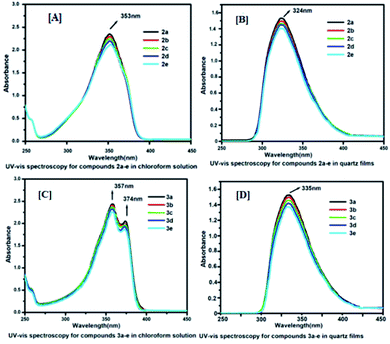 | ||
| Fig. 2 UV-Vis absorption spectra: Panels [A] and [B] for 2a–e in solutions and quartz films; Panels [C] and [D] for 3a–e in solutions and quartz films. | ||
Fluorescence measurement
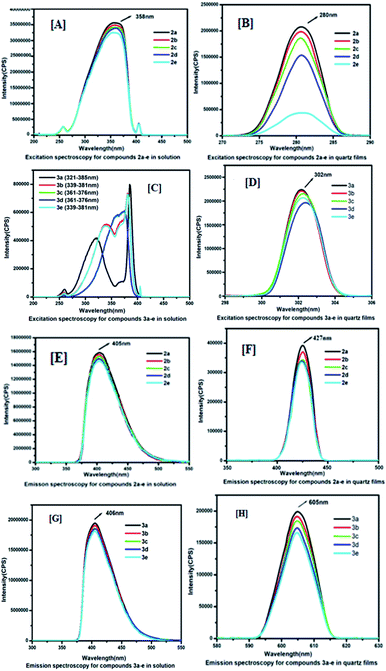
To understand the electronic excitation behaviour, we recorded the fluorescence spectra of compounds 2a–e and 3a–e in a chloroform solution at a concentration of 1.0 × 10⁻⁵ mol L−1 as well as in spin-coated thin films. The fluorescence spectra were recorded with excitation into the maximum of the longest wavelength absorption. Fig. 3[A]–[D] shows the excitation spectra of 2a–e and 3a–e in their solution and thin films. The excitation spectra were recorded for compounds 2a–e in solutions at 358 nm and the maximum absorption band at 353 nm, and for quartz films, it was excited at 280 nm and the absorption band appeared at 324 nm. Similarly, for compounds 3a–e, in the solution, the maximum excitation was recorded at 385 nm and maximum absorption band at 357 nm, and for quartz films, it was excited at 302 nm and the absorption band appeared at 335 nm. A longer excitation spectrum was recorded in solutions due to the presence of electron-withdrawing and -donating substituents that possess a strong push–pull system to exhibit high fluorescence intensities. The lower excitation of 3a–e in films may be attributed due to the compactness of the molecules via intermolecular hydrogen bonding between carboxylic acid functional groups.The emission spectra showed significant dependence on the excitation wavelength. The emission spectra of 2a–e and 3a–e in the chloroform solution (1.0 × 10⁻⁵ mol L−1) and quartz film at different excitation wavelengths are displayed in Fig. 3[E]–[H]. The emission spectrum for compounds 2a–e obtained by excitation at 358 nm has an emission maximum of 405 nm in the chloroform solution, whereas in spin-coated films, the excitation wavelength is 280 nm and emission maximum is 427 nm. However, the emission spectrum for compounds 3a–e obtained by excitation at 385 nm has an emission maximum of 406 nm in the chloroform solution (1.0 × 10⁻⁵ mol L−1), whereas in quartz films, the excitation wavelength is 302 nm and the emission maximum is 605 nm. The fluorescence excitation and emission data of 2a–e and 3a–e are summarized in Table 1.
| UV-Vis absorption/fluorescence excitation/emission | Compounds | |
|---|---|---|
| 2a–e | 3a–e | |
| UV-vis absorption maxima in solution | 353 nm | 357 nm |
| UV-vis absorption maxima of thin film | 324 nm | 335 nm |
| Fluorescence excitation maxima in solution | 358 nm | 385 nm |
| Fluorescence emission maxima in CHCl3 solution | 405 nm | 406 nm |
| Fluorescence excitation maxima of thin film (spin coated) | 280 nm | 302 nm |
| Fluorescence emission maxima of thin film (spin coated) | 427 nm | 605 nm |
Isotherm measurement/monolayer characteristics
In order to have an idea about monolayer properties, two extreme members [2a (n = 16, R = Et), 2e (n = 8, R = Et), 3a (n = 16, R = COOH), and 3e (n = 8, R = COOH) in Fig. 1] of each series of the coumarin derivatives were selected and then surface pressure–area per molecule isotherm (π–A) at the air–water interface using the Langmuir–Blodgett (LB) techniques was recorded. A dilute solution in chloroform (1.0 × 10⁻⁵ mol L−1) of 100 μL of each material was spread by a micro syringe on the water sub-phase of pure Milli-Q water (18.2 MΩ cm) at room temperature and allowed to evaporate. After complete evaporation of the volatile solvent, the barrier was compressed at a rate of 5 mm min−1 to record the surface pressure–area per molecule isotherms. The surface pressure (π) versus average area (A) available for one molecule was measured by a Wilhelmy plate arrangement.36 Each isotherm was repeated a number of times and data for surface pressure-area per molecule isotherms were obtained by a computer interfaced with the LB instrument. Before each isotherm measurement, the trough and barrier were cleaned with ethanol and then rinsed with Milli-Q water. The compound (2a, 2e, 3a and 3e) monolayer formed at the air–water interface was found to be stable and easily transferable onto the solid substrate to monolayer LB films. Fig. 4[A] shows the corresponding (π–A) isotherm curves of compounds 2a and 2e. The isotherm of compound 2a starts rising with an initial lift off area of 2.2 nm2 and for compound 2e it was observed at 2.3 nm2. It was found that the isotherm of compound 2a gets collapsed at 45 mN m−1, whereas the collapse occurred at the lower surface pressure at 38 mN m−1 for compound 2e, i.e. 2a forms a more stable film than 2e probably due to the presence of longer alkyl chains in 2a. However, isotherms of compounds 3a and 3e started rising with lift off areas 4.2 nm2 and 6.3 nm2 and gets collapsed after surface pressure 29 mN m−1 and 15 mN m−1 respectively (Fig. 4[B]). The isotherm profiles of compounds 3 (a, e) indicate a higher lift off area than the isotherm profiles of compounds 2 (a, e). The differences in lift off areas as well as collapse pressures for compounds 2 (a, e) and 3 (a, e) are probably due to the hydrophobicity and polarity of the compounds. Amongst all the compounds, 2a is more hydrophobic due to the long alkyl chain and ester group. In contrast, compound 3e is more polarizable in nature due to the presence of a carboxylic acid (COOH) group and a small alkyl chain than others.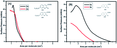 | ||
| Fig. 4 Surface pressure vs. area per molecule isotherms: [A] for (2a, 2e) and [B] for (3a, 3e). Inset shows the molecular structure of the compounds. | ||
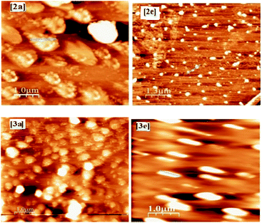
In order to have a deep idea about the surface morphologies of the thin films, we investigated the atomic force microscopic (AFM) images of spin-coated films. Fig. 5 shows the AFM images of compounds 2a, 2e, 3a and 3e in thin films deposited onto the smooth silicon substrate. The AFM images of spin-coated films revealed the sphere-like structures of aggregated 2a, 2e, 3a and 3e in the films, but the AFM line spectra of films of 2a and 2e indicated the clustering nature of the aggregates (see ESI†). Interestingly, all the sphere-like aggregates are uniformly distributed throughout the films, albeit they exhibited a small variation in dimensions as well as in heights. Since the dimension of the individual molecules is beyond the scope of resolution, it is not possible to distinguish individual molecules. After the analysis of height profile and line spectra (see ESI†) of AFM images (with respect to the empty substrate), it is estimated that the dimensions of sphere-like particles for compounds 2a, 2e, 3a and 3e are 200–250 nm, 150–250 nm, 200–300 nm and 120–170 nm respectively and heights are 10–12 nm, 10–12 nm, 12–14 nm and 7–8 nm respectively. As a whole, AFM images give us visual information about the formation of defined nano-structure aggregates (spherical in shape) of the compounds in the films.
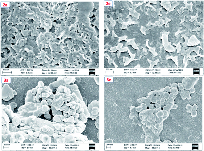
To get the insight into the surface morphology of the films prepared by spin-coated techniques, scanning electron microscopic (SEM) studies were carried out for four selected compounds by taking two from each series. Fig. 6 shows the SEM images of the compounds 2a, 2e, 3a and 3e. These images reveal that the molecules of the compounds 2a and 2e aggregated to form a cluster-like morphology, whereas 3a and 3e show a sphere-type surface morphology. We anticipated that the possible additional interaction via H-bonding in 3a and 3e aggregated in such a way that they appeared as spherical in shape but in other series (2a and 2e) due to the presence of the ester group, they aggregated to form a cluster-like morphology.
I–V characteristic studies of the compounds 2a–e and 3a–e
I–V characteristic of molecules (2a–e) in spin-coated films
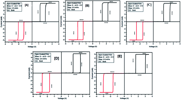
To study the electrical switching behaviour of coumarin derivatives 2a–e, the device having configurations Au/2x/ITO (where x = a, b, c, d and e) was prepared by spreading 1–2 drops of solutions on an ITO-coated glass substrate spun at a rotating speed of 1800 rpm. The resulting spin-coated films are dried sufficiently in vacuum at room temperature before the computation of I–V characteristics. The current–voltage behaviour was recorded by applying the voltage tuning from +Vmax to −Vmax and vice versa. The voltage was imposed on the top electrode (gold tip), whereas the bottom electrode (ITO-coated glass substrate) was held on ground potential.The electrical (I–V) measurement was performed by giving an active area of 1 mm2 for measurement. Same/different scanning/tuning voltages were applied to measure the I–V curves for all the devices at a voltage scan rate of 2.5 mV s−1. Fig. 7[A]–[E] shows the I–V curves of 2a–e. The device Au/2a/ITO exhibits a low conducting state (OFF state, 15.42 × 10⁴ Ω) for tuning the voltage range from +3.5 V to −3.5 V (scanning range was 0 to +3.5 to 0 to −3.5 to 0) (Fig. 7[A]), but the current was increased when the voltage approaches the threshold voltage (about 2 V), showing its high conducting state (ON state, 138.72 × 101 Ω). A similar procedure was followed for all other devices: Au/2b/ITO, Au/2c/ITO and Au/2d/ITO. The device Au/2e/ITO exhibits a threshold voltage of 3.0, and the resistance recorded in the OFF state is 5.11 × 10⁴ Ω and the on state is 165.49 × 101 Ω respectively. The results of I–V characteristics of these devices are listed in Table 2. From the results tabulated in Table 2, it is clear that with the decrease in the alkoxy chain length of 2 in the devices Au/2x/ITO, the threshold voltages increase with the decrease in resistance in the OFF state, whereas in the ON state, the resistance increases. No bipolar switching was observed in this series probably due to the hydrophobic and non-polar nature of 2a–e.
| Device configuration | Threshold switching | Resistances at | |||
|---|---|---|---|---|---|
| Threshold voltage (V) | Maximum compliance current (mA) | Minimum compliance current (mA) | OFF state (Ω) | ON state (Ω) | |
| Au/(2a)/ITO | 2 | 10 | 2 | 15.42 × 10⁴ | 138.72 × 101 |
| Au/(2b)/ITO | 2.2 | 10 | 2 | 12.79 × 10⁴ | 146.68 × 101 |
| Au/(2c)/ITO | 2.5 | 10 | 2 | 10.01 × 10⁴ | 150.93 × 101 |
| Au/(2d)/ITO | 2.7 | 10 | 2 | 8.21 × 10⁴ | 161.92 × 101 |
| Au/(2e)/ITO | 3 | 10 | 2 | 5.11 × 10⁴ | 165.49 × 101 |
I–V characteristic of molecules (3a–e) in spin-coated films
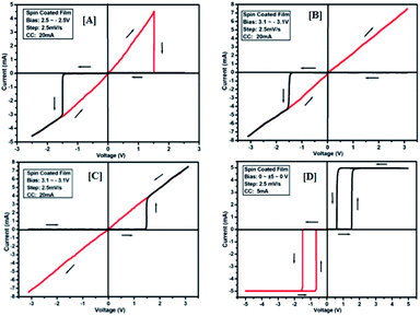
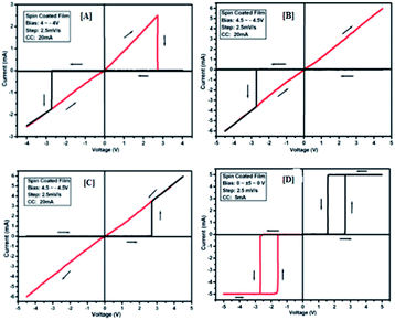
To study the switching behaviour of the compounds 3a–e, a device having configurations Au/3y/ITO (where y = a, b, c, d and e) was prepared by spin-coating techniques. The current–voltage behaviour measurement was studied by tuning the voltage from +Vmax to −Vmax and vice versa (with an increment of 0.1 V for Vmax each time). The I–V computation curve of the device having the configuration Au/3a/ITO for tuning the voltage range from +2.5 V to −2.5 V is shown in Fig. 8[A]. Initially, the above-mentioned device exhibits a low conducting state, by tuning the voltage range from +Vmax to −Vmax, but when the voltage closes to a threshold value of 1.5 V, it shows a high conducting state, and during scanning reverse i.e. −Vmax to +Vmax, the device shows transition from a high conducting state to a low conducting state (ON to OFF state) after reaching the threshold voltage (Fig. 8[A]).The similar bipolar switch could be formed independently by a maximum tuning voltage up to 3 V. It was found that the device sweeps to its ON state during tuning the voltage from +Vmax to −Vmax when the voltage exceeds 3 V, and during tuning −Vmax to +Vmax it does not return back to its low conducting state (Fig. 8[B]). Similarly, it was also observed that, when the voltage exceeds 3 V, then driving the device to its high conducting state (scanning from −Vmax to +Vmax) does not return back to its low conducting state (Fig. 8[C]) during scanning from +Vmax to −Vmax. It was noticed that by tuning, the compliance current transition from memory switching to threshold switching becomes irreversible. The bipolar switching cannot be recovered if the threshold switching is completely formed. Moreover, when applied to a higher voltage, i.e. 3.1 V in the device, it gets short circuit and shows only one way switching, it may be due to the organic layer between the electrodes in the ON state and the OFF state.46 However, in threshold and bipolar switching devices, the current in the OFF state is due to the low leakage of current.
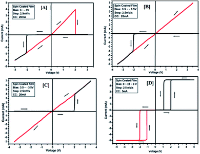
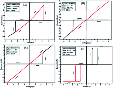
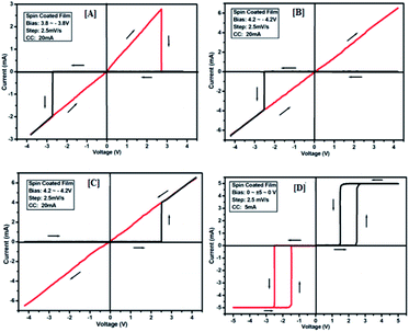
The results of the ON state and OFF state resistances (Ω) calculated from the I–V curve are listed in Table 3. Adjusting the measurement and all other protocols we have also investigated the threshold switching from the observed bipolar resistive switching of the same device. In case of both the forward and the reverse bias, the device shows threshold switching at fixed compliance current (5 mA). For threshold switching having the same configuration of the device (Au/3a/ITO) with scanning range 0 ± 5 to 0 V (Fig. 8[D]) showed a similar type of threshold switching by lowering the compliance current up to 2 mA. It was observed that there is no effect on the threshold switching if the sweep voltage range is more than 3.1 V. It is because the current increases besides the compliance level, which has no effect by increasing the sweep voltage and the device do not get short-circuited. In all the devices, the active junction area was 1 mm2 for I–V measurement. Similar trends were also observed for other devices Au/3b/ITO, Au/3c/ITO, Au/3d/ITO and Au/3e/ITO (Fig. 9–12). The results of all the devices are listed in Table 3.
| Device configuration | Bipolar switching | Threshold switching | Resistances at | |||||
|---|---|---|---|---|---|---|---|---|
| Threshold voltage (V) | Maximum allowed scanning voltage (V) | Shorted scanning voltage (V) | Threshold voltage (V) | Maximum compliance current (mA) | Minimum compliance current (mA) | OFF state (Ω) | ON state (Ω) | |
| Au/(3a)/ITO | 1.5 | 2.5 | 3.1 | 1.5 | 5 | 2 | 2.7 × 10⁴ | 43.00 × 101 |
| Au/(3b)/ITO | 2 | 3 | 3.5 | 2 | 5 | 2 | 3.3 × 10⁴ | 51.30 × 101 |
| Au/(3c)/ITO | 2.3 | 3.5 | 4 | 2.3 | 5 | 2 | 4.3 × 10⁴ | 79.20 × 101 |
| Au/(3d)/ITO | 2.5 | 3.8 | 4.2 | 2.5 | 5 | 2 | 5.8 × 10⁴ | 101.7 × 101 |
| Au/(3e)/ITO | 2.7 | 4 | 4.5 | 2.7 | 5 | 2 | 6.7 × 10⁴ | 104.4 × 101 |
During the I–V measurement, a gold tip, softly touching the surface of the prepared thin films (spin-coated), was used as the top electrode for an active junction area of 1 mm2 for measurement. However, we also measured the I–V characteristics for different devices by varying the active junction area, but no significant variation is observed.
From the study of the current–voltage measurement, it was found that the synthesised coumarin derivatives 2a–e show threshold switching, but compounds 3a–e show threshold as well as bipolar resistive switching. The observed bipolar switching behaviour may be explained due to polarizable carboxylic acid groups (–COOH) and electron-donating long alkoxy groups (–OC18H37, –OC16H33, –OC14H29, –OC12H25, –OC10H21) at position 3 of the coumarin ring. When the devices of coumarin derivatives 3a–e were scanned from a positive voltage to a negative voltage, it shows a very low OFF state leakage current. It may be due to the attractions between the presence of π-electron clouds in the cyclic ring of the coumarin core and the electron acceptor carboxylic acid group. The leakage of current may be restored by giving the electrons in the system by an electron-donating alkoxy group. Due to the presence of delocalized π-electrons in the entire molecules, it can be responsible to bear a conduction pathway to result in a high-conducting ON state. Moreover, when extra electrons were added through an electron-withdrawing alkyl group, it can oxidise the compound and the device returns to its OFF state during scanning from −Vmax to +Vmax. In case of threshold switching, the difference in work functions between the metals used as electrodes and the resulting built-in internal field determine the bias direction as well as at which the electron injection to the organic layer is favourable. Therefore, depending on the bias, the conjugation in the backbone of the molecule is presumably extended and this results in a high-conducting state. Moreover, due to the presence of the –COOH group, organizational behaviours of 3a–e are considerably different from those of 2a–e, as the hydrogen bond donor–acceptor phenomenon makes a highly organized assembly for 3a–e in the film, which is also reflected in the SEM images. However, it cannot be ruled out that the coumarin molecule may undergo ring-opening due to the presence of water molecules around the device followed by oxidation of phenolic compounds so generated to quinone.47 Therefore, as the biases applied are very large, the possibility of such quinone–hydroquinone oxidation–reduction process pathways could be another acceptable mechanism in the present studies.
The carrier conduction involves both injection and transport. Hence, electro-reduction of 2a–e and 3a–e compounds occurred and the device switches to its high state at a forward bias. I–V characteristic for bipolar resistive switching and threshold switching for two sweep direction of the spin coated film based Au/2a–e/ITO and Au/3a–e/ITO devices was prepared by spin coating technique. Spin-coated films are quite thick and they have good control in assembling of molecules onto thin films. It was observed that the device get short circuited when the scanning voltage goes beyond certain maximum limiting values. During the ON state when the current passes through the devices, the organic layer in the device is heated up. With the increase in current due to the increase in bias voltage, the extent of heating also increases and the device gets damage. To prevent such damage, the current flowing in the memory devices should be kept below compliance.
Conclusions
In summary, we have successfully explored novel coumarin derivatives appended with a long alkoxy chain on the seventh position of a coumarin-3-carboxylate/carboxylic acid core as potential candidates for futuristic materials to make devices of specific interest. The synthesised materials were characterized by different analytical tools such as NMR and mass spectroscopy, UV, fluorescence, AFM and SEM studies as well as I–V characteristic mapping respectively. From the I–V characteristics, it was found that at room temperature, the spin-coated films of coumarin derivatives containing an ester functional group exhibited a threshold switching behaviour, whereas the derivatives containing a carboxylic acid functional group shows both threshold and bipolar switching behaviours. We also noticed that the I–V characteristic features of the synthesized materials depend on the length of the alkyl chain of individual series. I–V characterized data reveal that these coumarin derivatives, particularly coumarin carboxylic acids 3a–e, could be useful as innovative futuristic materials for organic electronics and valuable applications in chemical, material and medical sciences.Author contributions
S. M. designed the work, A. R. P. synthesised the materials, NMR and mass spectral analyses, A. R. P., B. D. and S. S. performed all experiments and data analysis with input from S. A. H. and S. M., A. R. P and B. D. wrote the manuscript.Conflicts of interest
There are no conflicts to declare.Acknowledgements
The authors are grateful to Department of Science and Technology (DST), Govt. of India for providing 400 MHz NMR facility under DST-FIST programme (No SR/FST/CSI-263/2015) and Central Instrumentation Centre (CIC) Tripura University for Instrumental facilities. We also thank to honourable referees for their critical comments.Notes and references
- J. Kang, V. K. Sangwan, J. D. Wood and M. C. Hersam, Acc. Chem. Res., 2017, 50, 943–951 CrossRef CAS PubMed.
- C. Gong, K. Hu, X. Wang, P. Wangyang, C. Yan, J. Chu, M. Liao, L. Dai, T. Zhai, C. Wang, L. Li and J. Xiong, Adv. Funct. Mater., 2018, 28, 1706559 CrossRef.
- H. Klauk, Chem. Soc. Rev., 2010, 39, 2643–2666 RSC.
- Q.-H. Wu, P. Zhao and G. Chen, Org. Electron., 2015, 25, 308–316 CrossRef CAS.
- W. Ni, M. Li, B. Kan, Y. Zuo, Q. Zhang, G. Long, H. Feng, X. Wan and Y. Chen, Org. Electron., 2014, 15, 2285–2294 CrossRef CAS.
- G. Chen, C. Si, P. Zhang, B. Wei, J. Zhang, Z. Hong, H. Sasabe and J. Kido, Org. Electron., 2017, 51, 62–69 CrossRef CAS.
- A. Guerrero, M. Pfannmoller, A. Kovalenko, T. S. Ripolles, H. Heidari, S. Bals, L.-D. Kaufmann, J. Bisquert and G. Garcia-Belmonte, Org. Electron., 2015, 16, 227–233 CrossRef CAS.
- Y.-C. Lai, F.-C. Hsu, J.-Y. Chen, J.-H. He, T.-C. Chang, Y.-P. Hsieh, T. Y. Lin, Y.-J. Yang and Y.-F. Chen, Adv. Mater., 2013, 25, 2733–2739 CrossRef CAS PubMed.
- X.-Y. Sun, T. Liu, J. Sun and X.-J. Wang, RSC Adv., 2020, 10, 10826–10847 RSC.
- S. S. Bhattacharya, S. K. Paul, A. Mandal, N. Banerjee and A. R. Boujedaini, Eur. J. Pharmacol., 2009, 614, 128–136 CrossRef PubMed.
- C. Ito, M. Itoigawa, S. Onoda, A. Hosokawa, N. Ruangrungsi, T. Okuda, H. Tokuda, H. Nishino and H. Furukawa, Phytochemistry, 2005, 66, 567–572 CrossRef CAS PubMed.
- K. B. Gudasi, M. S. Patil and R. S. Vadavi, Eur. J. Med. Chem., 2008, 43, 2436–2441 CrossRef CAS PubMed.
- S. Sardori, Y. Mori, R. G. Micetich, S. Nishibe and M. Daneshtalab, Bioorg. Med. Chem., 1999, 7, 1993–1940 CrossRef.
- R. N. Gacche, D. S. Gond, N. A. Dhole and B. S. Dawane, J. Enzyme Inhib. Med. Chem., 2006, 21, 157–161 CrossRef CAS PubMed.
- I. Manolov, C. Maichle-Moessmer and N. Danchev, Eur. J. Med. Chem., 2006, 41, 882–890 CrossRef CAS PubMed.
- K. Ivana, J. Andrea and K. Pavol, Beilstein J. Org. Chem., 2006, 2(23), 1–5 Search PubMed.
- K. S. Lee, H. J. Kim, G. H. Kim, I. Shin and J. I. Hong, Org. Lett., 2008, 10, 49–51 CrossRef CAS PubMed.
- S. H. Zhou, J. H. Jia, J. R. Gao, L. Han, Y. J. Li and W. J. Sheng, Dyes Pigm., 2010, 86, 123–128 CrossRef CAS.
- H. N. Harishkumar, K. M. Mahadevanand and J. N. Masagalli, S. Afr. J. Chem., 2012, 65, 5–9 CAS.
- C. Murata, T. Masuda, Y. Kamochi, K. Todoroki, H. Yoshida, H. Nohta, M. Yamaguchi and A. Takadate, Chem. Pharm. Bull., 2005, 53, 750–758 CrossRef CAS PubMed.
- P. Y. Kuo and D. Y. Yang, J. Org. Chem., 2008, 73, 6455–6458 CrossRef CAS PubMed.
- P. O. Körner, R. C. Shallcross, E. Maibach, A. Köhnen and K. Meerholz, Org. Electron., 2014, 15, 3688–3693 CrossRef.
- V. W. W. Yam, H. O. Song, S. T. W. Chan, N. Zhu, C. H. Tao, K. M. C. Wong and L. X. Wu, J. Phys. Chem. C, 2009, 113, 11674–11682 CrossRef CAS.
- S. L. Cui, X. F. Lin and Y. G. Wang, Org. Lett., 2006, 8, 4517–4520 CrossRef CAS PubMed.
- K. S. Lee, H. J. Kim, G. H. Kim, I. Shin and J. I. Hong, Org. Lett., 2008, 10, 49–51 CrossRef CAS PubMed.
- N. Barooah, M. Sundararajan, J. Mohanty and A. C. Bhasikuttan, J. Phys. Chem. B, 2014, 118, 7136–7146 CrossRef CAS PubMed.
- J. Li, C. F. Zhang, S. H. Yang, W. C. Yang and G. F. Yang, Anal. Chem., 2014, 86, 3037–3042 CrossRef CAS PubMed.
- S. R. Trenor, A. R. Shultz, B. J. Love and T. E. Long, Chem. Rev., 2004, 104, 3059–3078 CrossRef CAS PubMed.
- C. L. Yi, J. H. Sun, D. H. Zhao, Q. Hu, X. Y. Liu and M. Jiang, Langmuir, 2014, 30, 6669–6677 CrossRef CAS PubMed.
- H. Q. Wu, P. Zhao and G. Chen, Org. Electron., 2015, 25, 308–316 CrossRef.
- S. L. Cui, X. F. Lin and Y. G. Wang, Org. Lett., 2006, 8, 4517–4520 CrossRef CAS PubMed.
- X. Ren, M. E. Kondakova, D. J. Giesen, M. Rajeswaran, M. Madaras and W. C. Lenhart, Inorg. Chem., 2010, 49, 1301–1303 CrossRef CAS PubMed.
- J. R. Koo, H. S. Lee, Y. Ha, Y. H. Choi and Y. K. Kim, Thin Solid Films, 2003, 438–439, 123–127 CrossRef CAS.
- S. Gao, X. Yi, J. Shang, G. Liu and R.-W. Li, Chem. Soc. Rev., 2019, 48, 1531–1565 RSC.
- F. Bigi, L. Chesini, R. Maggi and G. Sartori, J. Org. Chem., 1999, 64, 1033–1035 CrossRef CAS PubMed.
- A. Ulman, An introduction to ultrathin organic films: from Langmuir-Blodgett to self-assembly, Academic Press, Boston, 1991 Search PubMed.
- S. X. Wu, L. M. Xu, X. J. Xing, S. M. Chen, Y. B. Yuan, Y. J. Liu, Y. P. Yu, X. Y. Li and S. W. Li, Appl. Phys. Lett., 2008, 93, 043502 CrossRef.
- R. Waser, R. Dittmann, G. Staikov and K. Szot, Adv. Mater., 2009, 21, 2632–2663 CrossRef CAS.
- S. H. Chang, J. S. Lee, S. C. Chae, S. B. Lee, C. Liu, B. Kahng, D. W. Kim and T. W. Noh, Phys. Rev. Lett., 2009, 102, 026801 CrossRef CAS PubMed.
- D. B. Strukov, G. S. Snider, D. R. Stewart and R. S. Williams, Nature, 2008, 453, 80–83 CrossRef CAS PubMed.
- M. J. Lee, C. B. Lee, D. Lee, S. R. Lee, M. Chang, J. H. Hur, Y. B. Kim, C. J. Kim, D. H. Seo, S. Seo, U. I. Chung, I. K. Yoo and K. Kim, Nat. Mater., 2011, 10, 625–630 CrossRef CAS PubMed.
- A. Sawa, Mater. Today, 2008, 11, 28–36 CrossRef CAS.
- M.-J. Lee, Y. Park, D.-S. Suh, E.-H. Lee, S. Seo, D.-C. Kim, R. Jung, B.-S. Kang, S. E. Ahn, C. B. Lee, D. H. Seo, Y.-K. Cha, I.-K. Yoo, J.-S. Kim and B. H. Park, Adv. Mater., 2007, 19, 3919–3923 CrossRef CAS.
- I. Hwang, M. J. Lee, G. H. Buh, J. Bae, J. Choi, J. S. Kim, S. Hong, Y. S. Kim, I. S. Byun, S. W. Lee, S. E. Ahn, B. S. Kang, S. O. Kang and B. H. Park, Appl. Phys. Lett., 2010, 97, 052106–052108 CrossRef.
- H. Y. Peng, Y. F. Li, W. N. Lin, Y. Z. Wang, X. Y. Gao and T. Wu, Sci. Rep., 2012, 2, 442 CrossRef PubMed.
- P. Siebeneicher, H. Kleemann, K. Leo and B. Lüssem, Appl. Phys. Lett., 2006, 100, 094504 Search PubMed.
- S. Ciampi, M. James, G. LeSaux, K. Gaus and J. J. Gooding, J. Am. Chem. Soc., 2012, 134, 844–847 CrossRef CAS PubMed.
Footnote |
| † Electronic supplementary information (ESI) available. See DOI: 10.1039/d1ra00762a |
| This journal is © The Royal Society of Chemistry 2021 |


