 Open Access Article
Application of a blast furnace slag carrier catalyst in flue gas denitration and sulfur resistance
Zhang Lei *ad,
Lu Xia,
Qi Lingboa,
Shu Hao
 b,
Jia Yang
 b,
Lei Zhangc,
Yan Yaoa and
Bai Fange
aXi'an University of Science and Technology, Xi'an, 710054, China. E-mail: 136750178@qq.com; 1029571241@qq.com; 759809714@qq.com; 634122318@qq.com; Tel: +8618502993567
bXi'an University of Technology, Xi'an, 710048, China. E-mail: 490258879@qq.com; 519322049@qq.com
cChina National Heavy Machinery Research Institute Co, Ltd, Xi'an, 710032, China. E-mail: leizh666@sohu.com
dKey Laboratory of Coal Resources Exploration and Comprehensive Utilization, Ministry of Natural Resources, Xi'an, 710021, China
eCAS Key Laboratory of Green Process and Engineering, Institute of Process Engineering, Chinese Academy of Sciences, Beijing, 100190, China. E-mail: fbai@ipe.ac.cn
First published on 22nd April 2021
Abstract
It is an urgent need to develop a new catalyst with high efficiency and low cost. In the present study, we successfully prepared bimetallic-supported denitration catalysts using the blast furnace slag as the main material and calcium bentonite as the binder. The as-prepared catalyst was characterized via X-ray diffraction analysis (XRD), Fourier transform infrared spectroscopy (FTIR), and scanning electron microscopy (SEM). Besides, the mechanism of denitration was further determined with the help of the denitration and sulfur resistance of the catalyst. The results indicated that when the Mn load was 5%, and the second metal reactive component was loaded at 3%, Mn–Cu/GGBS (catalyst prepared by loading Mn and Cu on the blast furnace slag) had the best effects on low temperature denitration. Moreover, the conversion rate of NO was up to 97%, and it possessed the capability of specific sulfur resistance; when the third metal reactive component, Ce, was introduced with 1% load, the sulfur resistance of the Mn–Cu–Ce/GGBS (catalyst prepared by loading Mn, Cu, and Ce on the blast furnace slag) catalyst was further improved compared with that of the Mn–Cu/GGBS catalyst.
1. Introduction
Nitrogen oxides (NOx), the main air pollutants, mainly come from the combustion of coal and fossil fuels.1–3 We know that a large proportion of these emissions are from coal-fired power plants. In order to reduce pollution, one of the technologies adopted by most coal-fired power plants is selective catalytic reduction denitration, and the core of the SCR technology is the catalyst.2–5 Although some progress has been made in the study of SCR catalysts, the denitration catalyst is expensive and its sulfur resistance is insufficient.6–9 Consequently, the preparation of high performance denitration and sulfur-resistant catalysts characterized by high efficiency, simplicity, and energy conservation has become a hot topic in this field.10–12There are numerous types of catalysts in the world. For example, the SCR catalyst commonly used in industry is the vanadium-titanium catalyst, and this kind of catalyst tends to be poisonous and deactivated.13,14 Furthermore, the temperature window is wide, and V2O5 (one of the SCR catalysts) is highly poisonous.15–18 Therefore, it is necessary to develop a new catalyst with less pollution, low cost, and high efficiency.19 Zhang et al.20 successfully synthesized a V2O5/SnxTi1−xO2 catalyst by means of impregnation. Compared with the conventional V2O5/TiO2 (anatase) catalyst, V2O5/Sn0.2Ti0.8O2 has better low temperature SCR activity and better resistance to H2O and SO2. Taking Ce–TiO2 as the carrier, an active component, V2O5–WO3, was impregnated in the carrier by precipitation, and A. Kubilay21 finally prepared a V2O5–WO3/Ce–TiO2 catalyst and tested its denitration. It turned out that when there was a 250–475 °C temperature window and the conversion rate of NOx could reach more than 80%. The optimal reaction temperature was at 325 °C, and the denitration efficiency could reach up to 99% at that moment. According to the chemical deposition, Liu et al.22 prepared a CeO2–MnOx catalyst with a special core–shell structure, which was also characterized and tested for its denitration and activity. The result showed that when CeO2/MnOx ratio was 0.6 and the reaction temperature remained 110–220 °C, the NOx conversion rate was relatively high.23–27 Because of its special structure, the catalyst showed better sulfur resistance. However, most of these catalysts are powdery with poor mechanical properties, short service life, and high preparation cost.27–29
Blast furnace slag (GGBS) is a main industrial by-product during the process of blast furnace smelting of pig iron.30–32 There are CaO,33 MgO,34 SiO2,35 Al2O3,36 Fe2O3,37 and other oxide compositions accounted for more than 80%, so it is a type of mineral resource with high recycling value.38–42 With the rapid development of the steel industry, the mounting of slag emissions is visible. Therefore, a series of environmental problems exist in our life. For example, if slag is not emptied out in time, there will be a wide-occupation area and a large amount of accumulation.43 Rain also scours slag so that groundwater is polluted. Besides, the dust produced by the blow of slag endangers people's health. In order to make the slag resource effective, scholars in this field both at home and abroad take great advantage of the slag to make construction materials, cementitious materials, and others.44 In addition, blast furnace slag is also a cheap catalyst, widely used in the environmental sewage treatment, industrial catalyst preparation, soil remediation, and other fields.45
In this study, bentonite was used as a binder and transition metals as reactive components. The authors chose the blast furnace slag as the main raw material for the first time and prepared a low-cost, high-strength bimetallic blast furnace slag catalyst through equal volume impregnation. On the basis of equal volume impregnation, the blast furnace slag and bentonite were used as materials. The authors again successfully prepared a series of supported denitration catalysts. XRD, FT-IR, SEM, and other methods were used to characterize the catalyst. The denitration and sulfur resistance were also investigated. It turned out that the supported blast furnace slag-based catalyst has a good removal effect on NOx in flue gas and has good sulfur resistance. In summary, this research provides a clear research direction to find a low-cost and not easily powdered denitration sulfur-resistant catalyst. Simultaneously, it has achieved the goal of treating waste with waste and turning waste into treasure. Finally, it lays a theoretical foundation for the study of low-cost denitration sulfur-resistant catalysts in the future.
2. Materials and methods
2.1. The preparation of the catalyst
The blast furnace slag powder used in the experiment was obtained from a steel plant in Hanzhong, Shaanxi Province. The bentonite was produced by Tianyuan Non-metallic Products Co., Ltd and used without further purification. We mainly studied the formation of a blast furnace slag catalyst and the loading of different metals. The process was as follows: quantified blast furnace slag powder and calcium bentonite were mixed according to a mass ratio of 4![[thin space (1/6-em)]](https://www.rsc.org/images/entities/char_2009.gif) :
:![[thin space (1/6-em)]](https://www.rsc.org/images/entities/char_2009.gif) 1 in a beaker, 30 wt% of distilled water was added, stirred, and made a mass with specific humidity. The sample was loaded into the extruder. The extruded sample was kept in a 105 °C oven and dried for 1 h. After cooling, the sample was cut into a cylindrical carrier (equal height 5 mm) to reserve. Mn was mixed with nitrates from different metals proportionately. Mn was loaded at 5%, and the second metal (Cr, Co, Ni, Cu, Zn, Ag, Cd, and Fe) was loaded at 3%, via the same volume impregnation method. The blast furnace slag carrier was impregnated in a configured solution for 24 h and then taken out. The temperature of the drying box was adjusted to be 105 °C, and the loaded blast furnace slag base carrier was placed in a constant temperature drying box for drying. There was 15 minutes before it could be taken out. A series of catalysts could be prepared by 450 °C roasting for 2 h in a muffle furnace. These were Mn–Fe/GGBS, Mn–Co/GGBS, Mn–Ni/GGBS, Mn–Cr/GGBS, Mn–Cu/GGBS, Mn–Zn/GGBS, Mn–Ag/GGBS, and Mn–Cd/GGBS.
1 in a beaker, 30 wt% of distilled water was added, stirred, and made a mass with specific humidity. The sample was loaded into the extruder. The extruded sample was kept in a 105 °C oven and dried for 1 h. After cooling, the sample was cut into a cylindrical carrier (equal height 5 mm) to reserve. Mn was mixed with nitrates from different metals proportionately. Mn was loaded at 5%, and the second metal (Cr, Co, Ni, Cu, Zn, Ag, Cd, and Fe) was loaded at 3%, via the same volume impregnation method. The blast furnace slag carrier was impregnated in a configured solution for 24 h and then taken out. The temperature of the drying box was adjusted to be 105 °C, and the loaded blast furnace slag base carrier was placed in a constant temperature drying box for drying. There was 15 minutes before it could be taken out. A series of catalysts could be prepared by 450 °C roasting for 2 h in a muffle furnace. These were Mn–Fe/GGBS, Mn–Co/GGBS, Mn–Ni/GGBS, Mn–Cr/GGBS, Mn–Cu/GGBS, Mn–Zn/GGBS, Mn–Ag/GGBS, and Mn–Cd/GGBS.
2.2. The evaluation of catalyst activity
 | (1) |
3. Results and discussions
3.1 Synthesis and characterization of catalytic materials
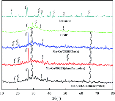
For GGBS, adding bentonite can increase the strength of the GGBS catalyst, and the SiO2 diffraction peak at 27.348° significantly enhanced. For the Mn–Cu/GGBS (fresh) catalyst, the diffraction peaks at 18.111° and 19.531° are MnO2 (PDF#44-0141) Mn5O8 (PDF#39-1218), and the diffraction peak at 35.262° is CuO (PDF#44-0706). The diffraction peak of the deactivated Mn–Cu/GGBS (deactivated) catalyst reduced, and the diffraction peak of MnO2 at 18.111° is not obvious. The intensity of the diffraction peak of Cu0.451Mn0.549O2 (PDF#41-0184) at 27.472° reduced. Before and after denitration and after sulfur resistance, the characteristic peak of the catalyst appeared at 65.573° (PDF#41-0184).
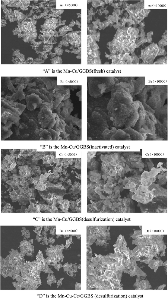
![[thin space (1/6-em)]](https://www.rsc.org/images/entities/char_2009.gif) 000 and 5000 times) of the Mn–Cu/GGBS catalyst before and after denitration as well as after sulfur resistance. (A) is the Mn–Cu/GGBS (fresh) catalyst. (B) is the Mn–Cu/GGBS (inactivated) catalyst. (C) is the Mn–Cu/GGBS (desulfurization) catalyst. (D) is the Mn–Cu–Ce/GGBS (desulfurization) catalyst.
000 and 5000 times) of the Mn–Cu/GGBS catalyst before and after denitration as well as after sulfur resistance. (A) is the Mn–Cu/GGBS (fresh) catalyst. (B) is the Mn–Cu/GGBS (inactivated) catalyst. (C) is the Mn–Cu/GGBS (desulfurization) catalyst. (D) is the Mn–Cu–Ce/GGBS (desulfurization) catalyst.
It can be seen from Fig. 4 that (A) is the Mn–Cu/GGBS (fresh) catalyst, and it passed through the high-temperature calcination stage, and the catalyst has just been formed. Therefore, the structure at the microscopic level is relatively loose. (B) is the Mn–Cu/GGBS catalyst (deactivated) after high temperature roasting. The active metal component impregnated on (A) is turned into metal oxide after high temperature roasting, which provides the basis for denitration and sulfur resistance. Under the catalysis of the active metal Mn–Cu, NOx reduces nitrogen oxides to N2 under the action of the reducing gas NH3. (C) is the Mn–Cu/GGBS catalyst after desulfurization (desulfurization). During the reaction, ammonium sulfate is generated and concentrated on the surface of the catalyst, reducing the voids and pore structure between the catalyst particles. Therefore, the denitration activity of the catalyst is reduced, and it is finally got deactivated. In addition, (D) is the Mn–Cu–Ce/GGBS (desulfurization) catalyst, which, like the fresh catalyst, also produces an agglomerated structure. The reduction in voids between the agglomerated structures is due to the accumulation of sulfides and sulfates. There was a reaction between Mn and S elements, so that manganese sulfide as well as manganese sulfate were produced to reduce the activity of Mn element. At this moment, the reactive component Ce in the catalyst had a more active electronic layer structure than Mn, which first reacted with SO2 to form cerium sulfide or cerium sulfate to protect the denitration performance of Mn. Therefore, the sulfur resistance of the Mn–Cu–Ce/GGBS catalyst was better than that of the Mn–Cu/GGBS catalyst after the introduction of the third reactive component Ce.
3.2. Catalytic properties of catalytic materials
The blast furnace slag was chosen as the main material, and the bimetallic supported blast furnace slag catalyst was prepared by equal volume impregnation. Mn was chosen as the first load metal and transition metals (Cr, Co, Ni, Cu, Zn, Ag, Cd, and Fe) as the second reactive component. The optimal bimetallic-supported blast furnace slag catalyst Mn–X/GGBS (X = Cr, Co, Ni, Cu, Zn, Ag, Cd, and Fe) was obtained by the denitration performance and characterization tests.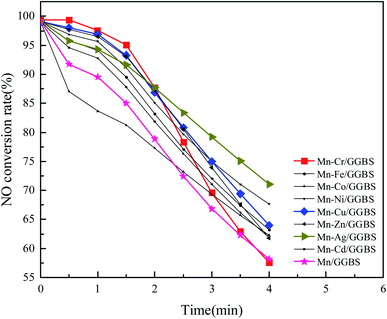 | ||
| Fig. 5 The effect of the bimetallic (Mn–transition metal) load on the denitration performance of the blast furnace slag. | ||
The results indicated the denitration effect at 150 °C and the first 2 min: Cr > Cu > Zn > Ni > Ag > Fe > Cd > Co. Compared to the Mn–Cu catalyst, the Mn–Ag bimetal supported blast furnace slag catalyst has better catalytic performance. However, the catalytic performance of the Mn–Ag bimetal supported blast furnace slag catalyst did not improve much. Also, Ag is expensive. According to a total comparison, the denitration rate of the blast furnace slag with the Mn–Cu bimetallic load was relatively slow, and its denitration effect was superior to that of other bimetallic supported catalysts. The denitration rate was still above 60% after 4 min. Moreover, it can be seen from Fig. 5 that the denitration performance of the bimetallic supported catalyst was obviously higher than that of the single component manganese-supported catalyst before deactivation. It means that the bimetallic-supported blast furnace slag could promote the denitration of the catalyst. The formed metal oxide was beneficial for denitration. The bimetallic co-impregnation was used to modify the blast furnace slag, so there were crystalline metal oxides except for MnOx as well as CuOx formed on the blast furnace slag after roasting by muffle furnace. Instead of adopting MnOx alone, Mn–Cu/GGBS supported the catalyst to obtain better redox reactions and more surface acidic sites with the help of Cu and Mn. Besides, bimetallic oxide (CuaMnbOx) with a certain crystal structure would also increase the performance of the catalyst to some extent, which accelerated the NH3–SCR reaction.
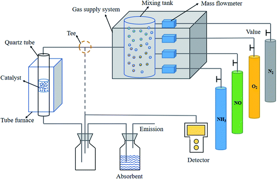
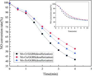
According to the results of the catalyst denitration in Fig. 5, Mn–Cr/GGBS, Mn–Cu/GGBS, and Mn–Zn/GGBS catalysts were quantified to be 10 g. These catalysts were put into a vertical furnace, and then SO2 was added to conduct the sulfur resistance test. At this moment, the flue gas flux was 500 mL min−1, O2 30 mL min−1, NO 8 mL min−1, SO2 2 mL min−1, NH3 8 mL min−1, and the rest was filled with N2. The effect of the bimetallic-supported catalysts on sulfur resistance was further obtained. The activity test results are shown in Fig. 6. According to the comparison, the denitration efficiency of the Mn–Cu/GGBS catalyst was better than that of the other two metal loads after SO2 was infused, which was consistent with the results of the experiment described in Section 3.2.1. Obviously, the as-prepared Mn–Cu/GGBS catalyst possesses good denitration performance and anti-sulfur effect.
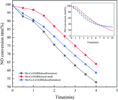
The prepared catalyst was put into a vertical furnace and then SO2 was added to conduct a sulfur resistance test. At this moment, the flue gas flux was 500 mL min−1, O2 was 30 mL min−1, NO was 8 mL min−1, SO2 was 2 mL min−1, NH3 was 8 mL min−1, and the rest was filled with N2. The effect of the tri-metallic supported catalyst on sulfur resistance was further obtained. The denitration results are shown in Fig. 7. After adding the third reactive component, Ce, the sulfur resistance of the Mn–Cu–Ce/GGBS catalyst was better than that of the Mn–Cu/GGBS catalyst. Obviously, the reactive component Ce accelerated the sulfur resistance against SO2 of the catalyst.
4. Conclusion
In this study, the blast furnace slag from industrial waste was chosen as the main material, and a certain amount of calcium bentonite was added as the binder to prepare the catalyst carrier. The authors worked out the denitration performance of a series of bimetallic and tri-metallic supported blast furnace slag catalysts by equal volume impregnation. In addition, a certain amount of SO2 was introduced into the simulated flue gas system to investigate the sulfur resistance against SO2 of the as-prepared catalyst. It was also analyzed by FT-IR, XRD, and SEM characterizations so as to not only determine the morphology, structures, and properties of the catalysts, but also analyze its denitration mechanism. The result indicated that it is feasible to use the blast furnace slag as the carrier of the denitration sulfur-resistant catalyst, which not only solves the problem of industrial waste pollution, but also achieves the aim of treating waste with waste and the recycling of waste. As an optimal bimetallic catalyst, Mn–Cu/GGBS possesses good denitration performance, and the NO conversion rate can reach up to 97%. Besides, it has sulfur resistance against SO2. The sulfur resistance of the Mn–Cu–Ce/GGBS tri-metallic supported blast furnace slag catalyst is better than that of the bimetallic-supported blast furnace slag catalyst.Conflicts of interest
None.Acknowledgements
Shannxi Key Research and Development Project (2019ZDLSF05-05-01); 2019 Shaanxi Provincial Natural Science Basic Research Program Enterprise Joint Fund Project (2019JL-01); Xi'an Science and Technology Plan Project (2019217714GXRC013CG014-GXYD13.4); Open Fund of Shaanxi Key Laboratory of Geological Support for Coal Green Exploitation (DZBZ2020-08).Notes and references
- H. Wang, J. Wang, G. Z. Bo, S. G. Wu and L. T. Luo, J. Cleaner Prod., 2020, 273, 123019 CrossRef CAS.
- J. Wang, Z. N. Yang, H. Wang, S. G. Wu, H. Lu and X. G. Wang, Sci. Total Environ., 2021, 758, 143670 CrossRef CAS PubMed.
- Y. L. Shan, J. P. Du, Y. B. Yu, W. P. Yu and H. He, Appl. Catal., B, 2020, 266, 118655 CrossRef.
- C. X. Huang, G. L. Li, L. M. Yang and E. Ganz, ACS Appl. Mater. Interfaces, 2021, 13, 608–621 CrossRef CAS.
- D. H. Jo, G. T. Park, T. Y. Ryu and S. B. Hong, Appl. Catal., B, 2019, 243, 212–219 CrossRef CAS.
- C. Peng, R. Yan, H. G. Peng, Y. Y. Mi and F. D. Liu, J. Hazard. Mater., 2020, 385, 121593 CrossRef CAS PubMed.
- B. Y. Song, Y. Zhou, H. M. Yang, J. H. Liao, L. M. Yang, X. B. Yang and E. Ganz, J. Am. Chem. Soc., 2019, 141, 3630–3640 CrossRef CAS PubMed.
- M. G. Villa, A. Aranzabal and M. P. González-Marcos, J. Ind. Eng. Chem., 2020, 81, 440–450 CrossRef.
- L. Zhang, Y. Jia, H. Shu, L. Zhang, X. Wen, M. Luo, Y. S. Wang and D. Xu, Fuel, 2020, 268, 117242 CrossRef.
- L. M. Yang, V. Bacic, L. A. Popov, A. L. Boldyrev, T. Heine, T. Frauenheim and E. Ganz, J. Am. Chem. Soc., 2015, 137, 2757–2762 CrossRef CAS PubMed.
- H. Wang, L. Zhang, Y. Tian, Y. Jia, G. Z. Bo, L. T. Luo and L. Liu, Chemosphere, 2021, 264, 128456 CrossRef CAS PubMed.
- W. Z. Si, H. Y. Liu, T. Yan, H. Wang and J. H. Li, Appl. Catal., B, 2020, 269, 312–326 CrossRef.
- J. Yang, X. L. Wang, Y. T. Qu, X. Wang, H. Huo, Q. K. Fan, J. Wang, L. M. Yang and Y. Wu, Adv. Energy Mater., 2020, 10, 2001709 CrossRef CAS.
- L. Zhang, Y. Jia, L. Zhang, H. B. He, C. Yang, M. Luo and L. T. Miao, J. Cleaner Prod., 2019, 217, 317–323 CrossRef.
- H. Wang, B. X. Quan, G. Z. Bo, Y. Z. Zhang, L. Liu, J. S. Zhang, X. Y. Zhang and C. H. Zhang, J. Cleaner Prod., 2020, 267, 122258 CrossRef CAS.
- J. H. Liu, L. M. Yang and E. Ganz, ACS Sustainable Chem. Eng., 2018, 6, 15494–15502 CrossRef CAS.
- S. H. Li, B. C. Huang and C. L. Yu, Catal. Commun., 2017, 98, 47–51 CrossRef CAS.
- Y. C. Choi, J. Y. Kim and S. C. Choi, Constr. Build. Mater., 2017, 137, 96–103 CrossRef CAS.
- J. H. Liu, L. M. Yang and E. Ganz, J. Mater. Chem. A, 2019, 7, 3805–3814 RSC.
- L. Zhang, H. Shu, Y. Jia, L. Zhang and D. Xu, Int. J. Hydrogen Energy, 2020, 45, 19280–19290 CrossRef.
- A. Kubilay, A. Semiha and A. Abdullah, Journal of Civil Engineering and Management, 2018, 22, 2994–3002 Search PubMed.
- J. H. Liu, L. M. Yang and E. Ganz, J. Mater. Chem. A, 2019, 7, 11944–11952 RSC.
- Y. H. Li, F. M. Chang, B. Huang, Y. P. Song, H. Y. Zhao and K. J. Wang, Fuel, 2020, 266, 117063 CrossRef.
- L. Zhang, H. Shu, L. Zhang and Y. Jia, ACS Omega, 2020, 5, 14911–14923 CrossRef PubMed.
- J. H. Liu, L. M. Yang and E. Ganz, RSC Adv., 2019, 9, 27710–27719 RSC.
- P. Itthikorn, H. Suksun, R. Runglawan, A. Arul and P. Prinya, J. Hazard. Mater., 2018, 341, 257–267 CrossRef PubMed.
- A. R. Hugo, C. R. Juan, F. P. Daniel, A. V. Hermes, A. R. Fredy, D. Farias and M. Muniz, J. Mater. Civ. Eng., 2018, 30, 04018244 CrossRef.
- L. Xu, L. M. Yang and E. Ganz, Theor. Chem. Acc., 2018, 137, 98 Search PubMed.
- Q. Song, H. Y. Zhao, J. W. Jia, Q. Y. Li, W. Lv, Q. X. Gu and X. Q. Shu, J. Anal. Appl. Pyrolysis, 2020, 145, 104716 CrossRef CAS.
- L. Zhang, H. Gao, X. Chang, Z. Lei, X. Wen and Y. S. Wang, J. Cleaner Prod., 2020, 249, 119307 CrossRef.
- J. J. Wu, H. Wang, X. Zhu, Q. Liao and K. Li, Appl. Therm. Eng., 2017, 111, 1557–1564 CrossRef CAS.
- M. Spanka, T. Mansfeldt and R. Bialucha, Environ. Sci. Pollut. Res., 2018, 25, 23082–23090 CrossRef CAS PubMed.
- L. Zhang, J. H. Chen, L. Zhang, H. B. He, Y. S. Wang and Y. H. Li, J. Cleaner Prod., 2019, 225, 220–226 CrossRef.
- M. Z. Wu, H. H. Lua, M. C. Liu, Z. L. Zhang, X. R. Wu, W. M. Liu, P. Wang and L. S. Li, Hydrometallurgy, 2017, 167, 8–15 CrossRef CAS.
- R. Tong, Z. Sun, X. N. Wang, L. M. Yang, J. W. Zhai, S. P. Wang and H. Pang, Int. J. Hydrogen Energy, 2020, 45, 18912–18921 CrossRef CAS.
- Q. Song, H. Y. Zhao, J. W. Jia, Q. Y. Li, L. Wen, J. W. Bao, X. Q. Shu, Q. X. Gu and P. Zhang, J. Cleaner Prod., 2020, 258, 120628 CrossRef.
- L. Zhang, L. B. Qi, H. Shu, Y. Jia, L. Zhang, C. Yang, F. Bai and Z. F. Sun, ACS Omega, 2020, 5, 31567–31574 CrossRef PubMed.
- D. M. Meng, Q. Xu, Y. L. Jiao, Y. Gao, Y. L. Wang, L. Li, G. Z. Zhan and C. Wang, Appl. Catal., B, 2018, 221, 652–663 CrossRef CAS.
- J. H. Liu, L. M. Yang and E. Ganz, Energy Environ. Mater., 2019, 2, 193–200 CrossRef CAS.
- L. Zhang, H. Shu, Y. Jia, Z. Lei, F. Bai, W. Kuang, L. B. Qi, J. Shang and C. Wei, Chemosphere, 2020, 128646 Search PubMed.
- Q. Song, H. Zhao, S. Q. Chang, L. Yang, F. Zou, X. Q. Shu, Q. Gu and P. Zhang, J. Anal. Appl. Pyrolysis, 2020, 151, 104927 CrossRef CAS.
- H. Y. Zhao, Y. H. Li, Q. Song, S. C. Liu, Q. X. Ma, M. Li and X. Q. Shu, Fuel, 2020, 286, 119398 CrossRef.
- J. C. Chen, J. H. Zhang, J. Y. Liu and H. Yao, Chem. Eng. J., 2020, 397, 125372 CrossRef CAS.
- H. Y. Zhao, Q. Song, S. C. Liu, Y. H. Li, X. H. Wang and X. Q. Shu, Energy Environ. Mater., 2018, 161, 13–26 CAS.
- J. H. Zhang, G. Sun, J. Y. Liu, F. Evrendilek and M. Buyukada, J. Cleaner Prod., 2020, 253, 119950 CrossRef CAS.
| This journal is © The Royal Society of Chemistry 2021 |

