 Open Access Article
Dissolution behavior of precious metals and selective palladium leaching from spent automotive catalysts by trihalide ionic liquids†
Arne Van den Bossche ,
Nerea Rodriguez Rodriguez
 ,
Sofía Riaño
 ,
Wim Dehaen
 and
Koen Binnemans
 *
*
Department of Chemistry, KU Leuven, Celestijnenlaan 200F, P.O. Box 2404, Leuven, B-3001, Belgium. E-mail: Koen.Binnemans@kuleuven.be; Tel: +3216327446
First published on 9th March 2021
Abstract
The dissolution behavior of the precious metals gold, platinum, rhodium and palladium in the trihexyl(tetradecyl)phosphonium trihalide ionic liquids [P66614][Cl3], [P66614][Br3], [P66614][IBr2] and [P66614][I3] was investigated. The highest dissolution rates were observed for the trichloride ionic liquid [P66614][Cl3] and this system was investigated in more detail. The effects of the trichloride concentration in the ionic liquid and temperature were studied, reaching higher leaching rates at higher trichloride conversions and increased temperatures. The stability of the trichloride anion at these elevated temperatures was studied by Raman spectroscopy. It was found that the trichloride anion decomposed during leaching at higher temperatures, showing the requirement to store these reactive compounds in sealed and cool environments, shielded from light. The optimal leaching conditions were applied for the recovery of palladium from ceramic monolith powder, obtained from end-of-life automotive catalysts. The catalyst powder was contacted with the ionic liquid [P66614][Cl3] and the metal concentrations in the ionic liquid were monitored. The trihalide ionic liquid allowed a more selective leaching of palladium compared to other metals present at very high concentrations in the monolith structure, like magnesium. The relative ratio of palladium over magnesium increased by two orders of magnitude compared to the original catalyst composition. The effect of the contact time between the catalyst powder and the ionic liquid on the metal concentrations in the leachate was investigated, but no significant improvement in the selectivity was observed.
Introduction
Platinum-group metals (PGMs) are crucial for the automotive industry because they are key elements in catalytic converters, which are part of the exhaust system of vehicles. The automotive catalysts purify the exhaust gasses before they are released into the atmosphere by catalyzing the reaction of toxic NOX and CO into N2 and CO2, and the oxidation of leftover hydrocarbons. PGMs are considered critical raw materials by the European Commission due to their high supply risk and economic importance.1 Recycling from end-of-life products, e.g. spent automotive catalyst, and substitution by less critical metals, e.g. gold,2 are the most promising solutions to reduce the criticality of PGMs. The recovery of PGMs from spent automotive catalysts is interesting because of the high price of the precious metals, and the high concentration of these metals compared to their abundance in primary ores. On average, catalytic convertors contain 2000 g per ton of PGMs, which is several orders of magnitude higher than the average concentrations of PGMs in ores, which typically contain less than 10 g per ton of PGMs.3The exhaust catalysts consist of a honeycomb structure called the ‘monolith’, made of cordierite: a synthetic silicate containing magnesium and iron.4,5 The catalytically active metals (mostly palladium, platinum and/or rhodium) are finely dispersed over this monolith together with other additives, mostly metal oxides, e.g. cerium(III,IV) oxide, that supply the oxygen for the reactions in the oxygen-lean phases of the combustion cycle.6 The monolith material is sintered to fix all the elements into place and to increase the heat and physical resistance of the structure.4 The disperse distribution of the PGMs, the complexity of the matrix with various elements in large concentration ranges, and the required oxidizing conditions are important considerations when designing recycling processes.
The recycling process starts with the isolation of the monolith, which is further processed by pyrometallurgy or hydrometallurgy.7 In the pyrometallurgical approach, the monolithic material is fed to a furnace together with other precious metal-containing waste. The precious metals are collected via so-called carrier metals, which are liquefied metal phases containing a variety of elements. A well-known carrier metal is lead, but copper is also commonly used for PGMs.8 The advantage of pyrometallurgical processes is the large volume and variety of waste that can be treated. The main disadvantages are the risks involved when working at high temperatures. Additionally, the energy demand for maintaining these high temperatures can be excessive if no combustible material is present in the feed. Furthermore, the individual PGMs cannot be separated from each other using pyrometallurgical methods. Therefore, a pyrometallurgical flow sheet must include final hydrometallurgical steps for the separation of the PGMs.9
In the hydrometallurgical approach, the metals are leached by a combination of strong mineral acids, oxidizing agents and/or strong ligands such as thiosulfate or cyanide.10,11 Hydrometallurgical processes are less energy-demanding than pyrometallurgical processes. However, they often lack selectivity towards the PGMs, meaning that most of the metal oxides present in the catalyst are also dissolved, and must be separated in other processing steps.7 A selective dissolution of the PGMs would solve the main disadvantage of hydrometallurgy. Halogens like chlorine, bromine and iodine are interesting alternatives, as they are oxidizing agents that do not contain any acidic protons.12–14 This is advantageous as the protons in other leaching agents (like mineral acids) recombine with the oxygen in oxides, forming water and thus facilitating the leaching of oxides. The absence of water and protons could make these halogens more selective towards metals and alloys in comparison to metal oxides. This emerging branch of metallurgy, in which the use of water is limited, is called “solvometallurgy”.15 Non-aqueous solvents with dissolved halogens are efficient in leaching a variety of metals.16–20 However, they hold substantial risks due to the high toxicity and volatility of the halogens, making them difficult to use in controlled reactions and safe conditions.21
This toxicity and volatility problem can be mediated by using trihalide ionic liquids, a special class of ionic liquids that contain a trihalide anion.22 Ionic liquids (ILs) are solvents that consist only of ions, and are typically liquid at low temperatures (<100 °C). The lower melting point is attributed to a disrupted lattice structure.23,24 They have many interesting properties, such as a broad electrochemical window, high metal solubility, high electrical conductivity and negligible volatility.23,25–28 The electrical conductivity is of particular interest in solvent extraction, as regular molecular solvents are insulators and accumulate static electricity. This can result in sparks and subsequent fires, which are avoided in ionic liquids by their intrinsic electrical conductivity and non-volatility.29,30 Trihalide ionic liquids were reported to be excellent oxidizing agents for metals.26,31–35 In this paper, we investigate the reactivity of trihalide ionic liquids towards the oxidation of the precious metals platinum, palladium, rhodium and gold. The selective leaching of those metals (apart from gold) from spent exhaust catalyst is also investigated.
Experimental
Chemicals
Trihexyl(tetradecyl)phosphonium chloride (Cyphos® IL 101 > 95%) and trihexyl(tetradecyl)phosphonium bromide (Cyphos® IL 102, 97%) were purchased from Cytec Industries (Niagara Falls, Canada). n-Heptane (>99%) and all the elemental standard solutions (1000 ppm) were ordered from Chem-Lab (Zedelgem, Belgium). Potassium iodide (99.9%), acetone (>99%) and absolute ethanol (99.8%) were purchased from Fisher Scientific (Geel, Belgium). Toluene (reagent grade) was ordered from VWR Chemicals (Haasrode, Belgium). Bromine (99.6%), 1-octanol (99%) and iodine (99.5%, resublimed) were purchased from Acros Organics (Geel, Belgium). Ethylene glycol (spectroscopic grade) was purchased from Sigma-Aldrich (Overijse, Belgium). The lecture bottle of liquefied chlorine (1 kg, 4.9 bar at 15 °C, > 99.5%) and the pressure regulator were purchased from Air Liquide (Liège, Belgium). The silicone solution in isopropanol was acquired from SERVA Electrophoresis GmbH (Heidelberg, Germany). Wires (diameter 0.5 mm) of platinum (99.95%), palladium (99.9%), rhodium (99.8%) and gold (99.95%), as well as powders of platinum (99.9%, <22 mesh) and rhodium (99.95%, <60 mesh), were purchased from Alfa Aesar (Haverhill, US). The spent catalyst was kindly supplied by Monolithos (Athens, Greece). Water used for analysis was always of ultrapure quality (resistivity 18.2 MΩ), provided by a Millipore Milli-Q Reference A+ system. The chemicals were used as received without any additional purification.Instrumentation
The exact mass of the metal wires was measured using a Mettler-Toledo XS105 DualRange analytical balance. 1H NMR spectra were recorded on a Bruker Avance 300 NMR spectrometer operating at 300 MHz. 31P NMR spectra were recorded on a Bruker Ascend 400 NMR spectrometer operating at 162 MHz. Samples for 1H NMR were diluted in deuterochloroform and internally referenced to tetramethylsilane. Samples for 31P NMR were diluted in deuterochloroform and externally referenced to 10 wt% H3PO4. The Spinworks 4.2.8 software was used in the analysis of the NMR spectra.A chlorine gas pressure regulator (DIM 200-3-5 T purge type) was used to adjust the pressure of outgoing chlorine gas between 0.3 and 3 bar. The chlorine gas flow meter (range: 2.1 to 21 g h−1 at 2 bar) was purchased from Brooks Instrument (The Netherlands). The absence of chloride and potassium ions after the metathesis reaction was confirmed by qualitative TXRF measurements on a Bruker S2 Picofox total reflection X-ray fluorescence spectrometer equipped with a molybdenum X-ray source at 50 kV voltage and 600 μA current. For the organic samples, 100 μL of ionic liquid were added with a Gilson Microman M1000 pipette to polypropylene Eppendorf microtubes, and diluted to a total volume of 1 mL with ethanol. For the aqueous samples, 500 μL of aqueous phase was diluted with ultrapure water to a total volume of 1 mL. Quartz glass carriers plates were precoated by a Serva® silicone/isopropanol solution (20 μL) and dried for 10 min at 60 °C. The samples (3 μL) were dropped onto the carriers and dried for 30 min at 60 °C. Each sample was prepared in triplicate (three carriers) and measured for 500 s.
Inductively coupled plasma-optical emission spectroscopy (ICP-OES) was used to measure the metal concentrations in the ionic liquid. A PerkinElmer Avio 500 spectrometer was used, equipped with a Meinhard low-flow nebulizer, baffled cyclonic spray chamber, 1.2 mm inner diameter alumina injector and PerkinElmer hybrid XLT torch. First, the ionic liquids were diluted 10 times in 1-octanol. A 1 mL sample of this solution, together with gallium and dysprosium internal standard solutions was then diluted with ethylene glycol. The final concentration of each internal standard corresponded to 10 ppm. Samples were prepared in duplicate. External calibration series containing the metals of interest and 10 ppm of both gallium and dysprosium were used to prepare calibration curves for the metal quantification in the ionic liquid phases (0.1–10 ppm). These calibration solutions were also prepared using ethylene glycol. A quality control (QC) sample with known metal concentration was measured after the calibration solutions and after the sample series to verify the suitability of the selected lines. A reagent blank was also prepared, and its emission intensity was subtracted from the metal solutions. The elemental spectroscopic lines were (in nm): Pt 299.797; Pd 363.470; Rh 343.489; Mg 285.213; Ce 418.660; Zr 343.823; Ba 233.527; Fe 238.204; Ti 336.121; Sr 407.771; Nd 406.109; Ca 317.933; Zn 206.200; Ni 231.604; Cu 327.393; Cr 267.716; V 290.880; As 188.979; Mn 259.372; Mo 202.031. These lines were measured in triplicate for all samples.
A Berghof Speedwave Xpert digester and 100 DAK vessels were used to digest the catalytic material. An Optima 8300 spectrometer from PerkinElmer with a 1-slot hybrid XLT ceramic-quartz torch, also from PerkinElmer, was used for the characterization. Raman spectra were recorded on a Bruker Vertex 70 spectrometer with a RAMII Raman module, and with a Nd-YAG laser (1064 nm) operating at 500 mW. All liquid samples were homogenized prior to the analysis. The data were analyzed using OPUS software (Bruker).
Pretreatment of the catalytic material
The catalyst material as received from Monolithos was already mechanically treated prior to its arrival. The samples have been derived after decanning/milling/homogenizing big commercial batches of spent automotive catalysts (1400 pcs per batch or 1 ton of milled ceramic cordierite). According to the supplier, the catalyst powder was collected after a milling step which reduced the particle size to <160 μm. The samples development and detailed preparation procedure is described by Yakoumis et al.36Characterization of the catalytic material
The composition of the catalytic material was determined via microwave digestion followed by ICP-OES analysis. For the digestion, the catalytic material (100 mg) was added to the reaction vessels and treated with the following aqueous acid solutions: 5 mL of HCl (37%) + 4 mL of HNO3 (65%) + 3 mL of HBF4 (48%) + 3 mL of H2O2 (35%), added in that order. Full digestion was achieved by: (1) ramping from ambient temperature to 170 °C in 8 min and holding for 8 min, (2) ramping to 200 °C in 15 min and holding for 35 min, (3) cooling down to 50 °C and holding for 5 min. After the digestion, the vessels were allowed to cool down further for one hour inside the digester and for one hour outside the digester. The digested samples were transferred to 25 mL volumetric flasks by rinsing with 37 wt% HCl. The digestion was performed in triplicate, and a blank sample was also digested to serve as a reagent blank for the ICP-OES analyses. The sample preparation for the ICP-OES analysis was as follows: the samples were diluted 10 times with 2 vol% HCl and yttrium (5 ppm) and cadmium (5 ppm) were used as internal standards. Hydrochloric acid was preferred over the more used nitric acid because it stabilized the PGMs in the solution. A QC was measured after the calibration line and at the end of the analysis sequence to verify the suitability of the selected lines. A reagent blank was also measured and subtracted.Purification of phosphonium ionic liquids
The quaternary phosphonium ionic liquids Cyphos IL 101 ([P66614]Cl) and Cyphos IL 102 ([P66614]Br) were water-saturated and n-heptane was added (twice the volume of the ionic liquid phase). The mixture was stirred at 70 °C for 1 hour and allowed to cool to ambient temperature, after which the two phases were separated. This washing process at elevated temperature and subsequent phase separation was repeated until several impurities (halo-alkanes, alkenes and trialkylphosphine oxides) were removed. The absence of halo-alkanes and alkenes was checked by 1H NMR and the absence of trialkylphosphine oxides by 31P NMR spectroscopy.Synthesis of trihexyl(tetradecyl)phosphonium iodide, [P66614]I
Cyphos IL 101 (75 g) was diluted using 30 mL of toluene in order to enhance phase separation. The solution was added to a separation funnel and 75 mL of a 500 g L−1 potassium iodide solution was added. The mixture was stirred on a stirring plate for 2 h at ambient temperature and after settling the two phases were separated. The ionic liquid phase was washed three additional times with the potassium iodide solution, the last time using only 25 mL instead of 75 mL. To confirm the complete conversion from chloride to iodide ionic liquids, the chloride content of both the ionic liquid phase and the potassium iodide washing solution was qualitatively analyzed using TXRF. The detection limit using this setup is 20 ppm for chlorine (as an impurity in ionic liquids), as determined by Vander Hoogerstraete et al.37 After the fourth washing step neither of the phases contained any chloride ions. The ionic liquid phase was washed several times with ultrapure water and the aqueous phase was also tested for the presence of potassium ions using TXRF, in order to make sure that no potassium iodide remained present in the ionic liquid. The toluene was removed using a rotary evaporator and the ionic liquid was dried overnight on a high vacuum line at 60 °C.Synthesis of trihalide ionic liquids
The trihalide ionic liquids [P66614][Cl3], [P66614][Br3], [P66614][IBr2] and [P66614][I3] were prepared by addition of halogens (chlorine, bromine or iodine) to the appropriate halide ionic liquid. These additions were carried out as described in a previous publication by our group.26 The ionic liquids were shielded from light using aluminum foil, to prevent homolytic cleavage of the halide bonds, and stored in a fridge with an inside temperature of −2.7 °C.Metal dissolution
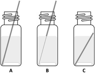
The oxidation and dissolution of the PGM wires in different ionic liquids was studied by submerging the wires in ionic liquids or mixtures of halide and trihalide ionic liquids. The ionic liquids were shielded from light, either by using amber colored vials or sealing the entire setup with aluminum foil. The wires were cut in pieces of equal length and placed into the vials. Afterwards, the ionic liquid was added and the mixtures were stirred at 100 rpm. The wires were periodically removed from the ionic liquid mixtures, washed with acetone, dried, and weighed on an analytical balance. In the graphs that visualize the dissolution, some sets do not show data points for the entire duration of the experiment. This means that at a certain moment, the wire was completely dissolved at one point of its length and could not be measured anymore (Fig. 1: situation C). Despite the fact that some parts of the wire remained and could be weighed, this would be an incorrect data point since ‘fresh’ metal parts that were not in contact with the ionic liquid, now became corroded. The data would not be representative and therefore not comparable with the other sets. These different steps are visualized in Fig. 1. For some experiments slight modifications were made: the vials were closed with a screw cap in order to keep the air and fumes in the vials. In these cases the metal wires were cut slightly shorter, so that they would not stick out of the vial, but still higher than the ionic liquid level so the wires could be taken out without touching the ionic liquid. The metal wires were not completely submerged since some ionic liquids were too dark to easily retrieve the metals wires if they would be submerged.Catalyst leaching
Catalyst powder samples were placed in a 4 mL vial and 2 mL of ionic liquid was added, the mixtures were stirred at 100 rpm for 48 hours unless stated otherwise. The vials were covered from light using aluminum foil. When aliquots were taken from the ionic liquid phase for analysis, the samples were centrifuged at 3500 rpm for 15 min and a sample of the supernatant was taken in such a way that no catalyst powder would be sucked into the pipette. The samples were diluted and analyzed as described above.Results and discussion
Leaching of precious metal wires in various trihalide ionic liquids
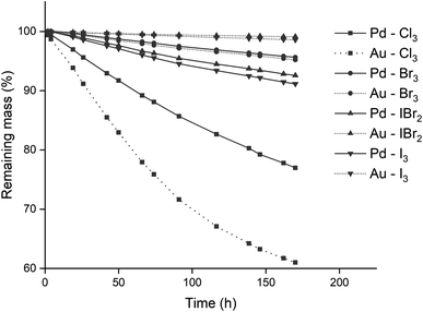
The reactivity of different trihalide ionic liquids with precious metals was investigated. Precious metal wires of equal diameter were submerged in equal volumes of various trihalide ionic liquid. This resulted in an identical surface area of wire exposed to the ionic liquid. Four metal wires were used (gold, palladium, platinum and rhodium) in combination with four different trihalide ionic liquids: [P66614][Cl3], [P66614][Br3], [P66614][IBr2] and [P66614][I3]. The trihexyl(tetradecyl)phosphonium cation was selected due to its resistance to chlorination by chlorine gas and since its chloride and bromide salts are commercially available as Cyphos IL 101 and Cyphos IL 102, respectively. The conversion of these two ionic liquids to the different trihalides is discussed in the Experimental section. Besides the homoatomic trihalides (X3− with X = Cl, Br or I), a mixed trihalide ionic liquid (XY2−) was used to compare its reactivity with the homoatomic trihalides. The iodide dibromide anion (IBr2−) was used due to its straightforward synthesis and higher stability.38 The wires were submerged in equimolar mixtures of monohalide and trihalide ionic liquids instead of pure trihalide ionic liquids. This way an excess of halide anions was present, which could form complexes with the metal ions after oxidation. This is required for the formation of metal halide complexes of metals that are oxidized to a 2+ oxidation state, see reaction eqn (2). The effect of the ionic liquid anion and contact time was studied, and the results are summarized in Fig. 2. The wires did not reach 100% of dissolution as about half of the length was submerged in the ionic liquid.Both rhodium and platinum wires were not oxidized by any of the trihalide ionic liquids, as the mass differences over time were negligible and could be explained by fluctuation of the analytical balance (see Fig. S1 in the ESI†). The gold and palladium wires on the other hand, were slowly dissolved by all trihalide ionic liquids, especially [P66614][Cl3], as visualized in Fig. 2. The proposed reaction equations for the leaching of gold and palladium by the used trihalide/halide ionic liquid mixtures are:
| 3[P66614][X3] + 2Au → 2[P66614][AuX4] + [P66614][X] | (1) |
| [P66614][X3] + [P66614][X] + Pd → [P66614]2[PdX4] | (2) |
Leaching of precious metal powders in trichloride ionic liquids
In order to verify that the lack of reactivity was not due to slow kinetics of platinum and rhodium, leaching experiments with fine powders were performed. By using powder instead of wires, the metal surface available for leaching was drastically increased. Two solutions of 50 mg of metallic powder (platinum: <22 mesh, and rhodium: <60 mesh) in 3 mL of [P66614][Cl3] were prepared and stirred at 100 rpm at 22.5 °C. Afterwards, the samples were centrifuged at 3500 rpm for 20 min and the ionic liquid phase was separated and analyzed using ICP-OES. Two aliquots of ionic liquid were taken and both samples were analyzed in duplicate, the results and subsequent analyses are listed in the ESI.† The platinum and rhodium concentrations in both samples were too low, sometimes even lower than that of the reagent blank (see Fig. S2 and S3 in the ESI†). It was thus concluded that both concentrations could be regarded as zero and that even when using fine powders with high surface area, platinum and rhodium did not dissolve.The inertness of platinum and rhodium towards the oxidizing trihalide ionic liquids might seem remarkable, since PGMs can be dissolved in hydrochloric acid with chlorine. However, the speciation of these PGMs in aqueous solutions and the corresponding redox potentials of the metals and halogens can be completely different when working in non-aqueous conditions. Thus, there is no guarantee that aqueous solutions are perfectly representative systems for the non-aqueous trihalide ionic liquids used in this research.
Effect of the temperature
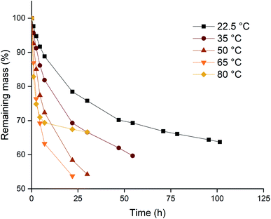
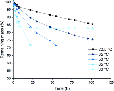
Based on the higher leaching rates, the ionic liquid [P66614][Cl3] was selected as the most promising candidate, and its leaching behavior was studied further. The effect of the temperature on the leaching efficiency was investigated for palladium and gold. Platinum and rhodium were not considered in this experiment because of their inertness towards the trihalide ionic liquids. Palladium and gold wires were dissolved in [P66614][Cl3] as described above. The solutions were kept at different temperatures throughout the entire experiment. The results of both the palladium and gold wires are shown in Fig. 3 and 4. It is clear from both figures that increasing the leaching temperature increases the dissolution rate. This is an expected consequence of the increased reactivity and the lower viscosity.One remarkable observation is that, even though the dissolution rates were increasing with temperature, the dissolution of samples that are heated to 80 °C (◆ in Fig. 3 and 4) suddenly slowed down drastically. For the palladium wire, the dissolution process even completely stopped. One hypothesis to explain this sudden halt in dissolution was loss of the reactive species, the trichloride anion, at elevated temperatures. This loss of trichloride might happen either due to loss of volatile chlorine, or due to chlorination reactions. Raman spectroscopy was used to check the loss of trichloride anions throughout the reaction. Several vials with pure ionic liquid were exposed to the same conditions, but without metal wires being present. The investigation of these samples showed that the halted reactions could indeed be attributed to loss of trichloride species, as will be discussed below.
Dissolution of gold and palladium using different trichloride concentrations
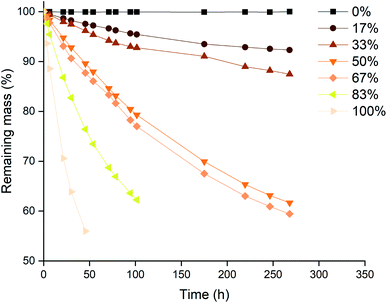
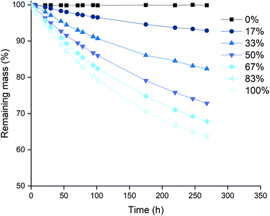
The next series of experiments was performed in closed vials at low temperatures in order to suppress the loss of trichloride species as much as possible (vide infra). The vials were closed using screw caps as described in the Experimental section. The effect of the level of trichloride conversion on the dissolution rate was investigated. This conversion difference was achieved by mixing pure [P66614]Cl and [P66614][Cl3] in different ratios, and is expressed in percentages: 100 times the ratio of trichloride (Cl3−) per cation (P66614+), where 0% corresponds to pure [P66614]Cl, 100% equals pure [P66614][Cl3] and 50% an equimolar mixture of the two. Similarly to the previous experiment, platinum and rhodium were not tested due to their inertness. The results for gold and palladium are summarized in Fig. 5 and 6.A first observation from Fig. 5 and 6 is that for palladium, increasing the conversion results in a steady increase in leaching rate for the wire, while for gold, there seem to be rather large and incoherent differences. Overall, the dissolution of gold occurred faster than that of palladium, which occurred for all conversions except for 33%. This is in agreement with the observations made in Fig. 2, where gold also dissolved faster than palladium.
A possible explanation for the higher increase in dissolution rate for gold compared to palladium can be found in the formed chloro-complexes of these metals: [AuCl4]− and [PdCl4]2−. Both anions become part of the ionic liquid structure, and can therefore influence the ionic liquid properties. The tetrachloropalladate(II) anion bears a higher negative charge, which will result in an increased viscosity when the metal is being dissolved. This can be explained by a higher charge density and thus stronger interaction between the ions. Dissolution of gold, forming tetrachloroaurate(III) anions with only a single negative charge, will result in a lower viscosity increase compared to the dissolution of palladium. Since high viscosities counteract the renewal of fresh trichloride ionic liquid at the surface of the wires, this will result in slower dissolution rates. This was also proposed and demonstrated by Vander Hoogerstraete et al., comparing the viscosity of ionic liquid containing cobalt and iron complexes, forming −2 and −1 charged halide salts, respectively.39
Stability of the trichloride anion
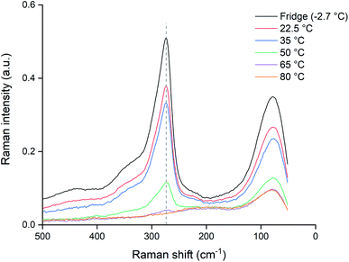
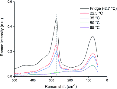
Since the dissolution of palladium at 80 °C halted almost completely after 24 hours, as shown by Fig. 4, the potential loss of trichloride was investigated. Pure ionic liquid solutions without metal wires were heated under the same conditions and a Raman spectrum was measured after 24 hours, which was compared to a reference sample that was sealed and stored in a fridge (−2.7 °C). The results are summarized in Fig. 7, where the Raman signal of the trichloride anion is situated at about 270 cm−1.The trichloride concentration was drastically reduced after 24 hours when the samples were heated. For the samples kept at 80 °C, the Raman peak had even completely disappeared. Therefore, the halted dissolution observed for some wires (Fig. 4) is indeed caused by a complete loss of reactive trichloride anions. This loss of trichloride species is not translated to the mass loss for the lower temperatures in Fig. 3 and 4. The wires dissolved before all the trichloride species had decomposed, therefore the mass loss did not stop like it did for the samples at 80 °C, but Fig. 7 clearly shows that at lower temperatures the loss of trichloride also occurs.
In order to check if the samples kept at lower temperatures (<80 °C) would also fully decompose if exposed to higher temperatures for a longer time, the samples were kept at their elevated temperatures for an additional 48 hours and re-measured. As can be seen from the results in Fig. 8, exposing the samples to increased temperatures longer than 24 hours causes further decomposition. The sample at 65 °C was also completely depleted of trichloride and for the sample at 50 °C, only a negligible amount remained. Even the samples at 22.5 and 35 °C showed losses of trichloride after 72 hours. The fact that the difference between the 22.5 and 35 °C samples was much smaller than the difference of both samples compared to the reference, indicates that not only the temperature, but also exposure to air and light might contribute to the decomposition of trichloride ions.
Upon examination of the heated ionic liquid samples, it became evident that the loss of the trichloride anions was partly caused by the volatility of chlorine. When looking at the results in Fig. 9 (pure ionic liquid heated with open vials), two different colors are observed in the ionic liquid. The yellow color of the top layer indicates that it contains trichloride species. This is most likely caused by the volatility of chlorine, which is being driven from the ionic liquid by increased temperatures (as the effect is more profound for the samples at higher temperatures: >35 °C). Another explanation could be that the trichloride reacts with the cation, and is reduced in the processes. However, if this would occur, the two colored layers (the yellow trichloride ionic liquid and the transparent chloride ionic liquid) should be reversed: the heavier trichloride ionic liquid should be present as the bottom layer instead of the top layer. The observation that the trichloride anions are predominantly present in the upper parts of the ionic liquid, implies that the volatility of chlorine is at least partially responsible for the decomposition of trichloride anions. The two colored layers should therefore be seen as one phase of chloride ionic liquid, with chlorine moving upwards, instead of two distinctly different ionic liquid phases.
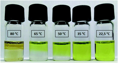 | ||
| Fig. 9 Heated samples of the trichloride ionic liquid [P66614][Cl3] after 24 hours, the vials remained open during heating and the samples were not stirred. | ||
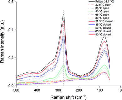
The experiment was repeated with closed vials in order to suppress the loss of chlorine to the air. The samples were heated identically to the opened vials and measured using the same Raman setup and procedures. These data are summarized in Fig. 10, where the closed vials are given by the full lines and the opened vials as the dotted lines. A first observation is that for temperatures of 65 and 80 °C, both the opened and unopened vials showed no remaining Raman peaks around 270 cm−1, indicating a full loss of trichloride species after 24 hours. In the other samples, the trichloride signal for the opened samples was lower than for the closed samples, implying that exposure to the air is causing the trichloride loss in the ionic liquid. A reassuring observation is that for the closed samples at 22.5 °C, the loss of trichloride species was limited. According to the Raman signal intensity at 273 cm−1, the sample still contained 90% of the original trichloride concentration compared to the reference sample (Fig. 10). Performing the experiments at ambient temperature and with closed vials is therefore the best in terms of trichloride, and thus reactivity, retention.
Leaching of palladium from spent catalyst
In order to test the dissolution of palladium by trihalide ionic liquids on real end-of-life waste, some milled spent exhaust catalyst was used. Trihalide ionic liquids were considered ideal for this application as they can be used to selectively leach palladium from the powder, leaving the other PGMs (platinum and rhodium) and the ceramic honeycomb structure unaffected. The latter is not leached since the trihalide ionic liquids don't contain protons and therefore do not readily leach oxides. This is in contrast to mineral or organic acids that are often used as leaching agents in metallurgical processes.Exhaust catalysts are purposely designed to be extremely resistant, due to the harsh conditions they are exposed to, and the long lifetime that is required. Moreover, the precious metals are amongst the most noble metals and thus very difficult to be attacked by acids. For these reasons, full dissolution of the spent catalyst for ICP-OES analysis required harsh conditions, involving microwave digestion with several concentrated acids. The sample was digested and analyzed as described in the Experimental section, the results are shown in Table 1.
| Element | Average | St. dev. |
|---|---|---|
| Pt | 670 | 25 |
| Pd | 1761 | 73 |
| Rh | 267 | 4 |
| Mg | 57![[thin space (1/6-em)]](https://www.rsc.org/images/entities/char_2009.gif) 479 479 |
1829 |
| Ce | 8914 | 1335 |
| Zr | 27![[thin space (1/6-em)]](https://www.rsc.org/images/entities/char_2009.gif) 137 137 |
433 |
| Ba | 15![[thin space (1/6-em)]](https://www.rsc.org/images/entities/char_2009.gif) 635 635 |
149 |
| Fe | 18![[thin space (1/6-em)]](https://www.rsc.org/images/entities/char_2009.gif) 782 782 |
732 |
| Ti | 8968 | 256 |
| Sr | 1741 | 43 |
| Nd | 511 | 69 |
| Ca | 3133 | 234 |
| Zn | 1990 | 63 |
| Ni | 404 | 16 |
| Cu | 77 | 4 |
| Cr | 348 | 17 |
| V | 305 | 6 |
| As | 87 | 14 |
| Mn | 185 | 7 |
| Mo | 42 | 1 |
The high concentrations of certain metals in the catalyst sample can be explained by the structure of monolith support. Magnesium and iron for instance, are present in cordierite, a popular aluminum silicate used for the monolithic support due to its low thermal expansion coefficient.4 Since the honeycomb structure is suitable for extrusion, materials with a low thermal expansion (like cordierite) are often used.5 The presence of cerium, barium and zirconium can also be explained by their specific function inside the catalyst.6 Cerium(III,IV) oxide is present as it is important in controlling the oxygen levels inside the catalyst. Zirconium is a popular additive to the cerium oxide as it enhances the physical properties of the system. Barium oxide is added to enhance catalyst properties: its activity and thermal resistance.40
Leaching the precious metals from the ceramic monolith structure was performed using the most reactive of the tested trihalide ionic liquids: [P66614][Cl3]. In a first experiment, several solid to liquid ratios were tested: three different samples of 2 mL of [P66614][Cl3] were prepared, with 10, 50, or 500 mg of catalyst material per mL of ionic liquids. The samples were treated as described in the Experimental section and analyzed using ICP-OES. The results are summarized in Table 2, where an overview of the metal concentrations in the ionic liquid leachates is given.
| Metal | mg sample per mL IL | ||
|---|---|---|---|
| 10 | 50 | 500 | |
| ppm | ppm | ppm | |
| Pt | 7 | 25 | 114 |
| Pd | 21 | 112 | 574 |
| Rh | 1 | 2 | 12 |
| Mg | 5 | 31 | 181 |
| Ce | 86 | 377 | 2363 |
| Zr | 14 | 32 | 193 |
| Fe | 100 | 441 | 2539 |
| Ti | 6 | 16 | 109 |
| Sr | 1 | 2 | 5 |
| Nd | 0 | 11 | 69 |
| Ca | 15 | 47 | 127 |
| Zn | 22 | 84 | 436 |
From the results in Tables 1, 2 and 3, it can be concluded that palladium was quantitatively leached. However, many unwanted and unexpected metals were codissolved. Surprisingly, substantial amounts of platinum and also some traces of rhodium were leached alongside palladium. This is in sharp contrast to what was observed in the previous experiments, where both elements could not be dissolved. A possible explanation might be that some platinum already got oxidized during the lifetime of the catalysts. This is a common issue in catalyst recycling, and conventional recycling processes even implement reduction steps prior to leaching.41 Another possible cause is the distribution of the metals in the monolith: if metal phases are intertwined, then leaching one metal might detach the other. The high leaching yields of other metals, especially iron and cerium, are also quite unexpected, as they should be present as oxides. Probably, their composition changed during the lifetime of the catalyst, making them more prone to leaching by the trichloride ionic liquid. Overall the leaching of palladium showed good selectivity over various other metals like magnesium, strontium, titanium and zirconium. The selectivity of palladium over magnesium is remarkable: their ratio in the catalytic material is 32![[thin space (1/6-em)]](https://www.rsc.org/images/entities/char_2009.gif) :
:![[thin space (1/6-em)]](https://www.rsc.org/images/entities/char_2009.gif) 1 Mg
1 Mg![[thin space (1/6-em)]](https://www.rsc.org/images/entities/char_2009.gif) :
:![[thin space (1/6-em)]](https://www.rsc.org/images/entities/char_2009.gif) Pd (Table 1). However, in the leachates in Table 2 this ratio is close to 1
Pd (Table 1). However, in the leachates in Table 2 this ratio is close to 1![[thin space (1/6-em)]](https://www.rsc.org/images/entities/char_2009.gif) :
:![[thin space (1/6-em)]](https://www.rsc.org/images/entities/char_2009.gif) 4 Mg
4 Mg![[thin space (1/6-em)]](https://www.rsc.org/images/entities/char_2009.gif) :
:![[thin space (1/6-em)]](https://www.rsc.org/images/entities/char_2009.gif) Pd for all tested solid-to-liquid (S/L) ratios. This corresponds to an increase of the ratio of palladium higher than two orders of magnitude. Table 3 was added to compare these results to the total amount of metal that is present in the catalyst samples, based on Table 1, and taking into account the different S/L ratios used in the different samples.
Pd for all tested solid-to-liquid (S/L) ratios. This corresponds to an increase of the ratio of palladium higher than two orders of magnitude. Table 3 was added to compare these results to the total amount of metal that is present in the catalyst samples, based on Table 1, and taking into account the different S/L ratios used in the different samples.
| Metal | mg sample per mL IL | ||
|---|---|---|---|
| 10 | 50 | 500 | |
| % | % | % | |
| Pt | 102 | 72 | 33 |
| Pd | 125 | 120 | 64 |
| Rh | 2 | 12 | 9 |
| Mg | 1 | 1 | 1 |
| Ce | 99 | 80 | 52 |
| Zr | 5 | 2 | 1 |
| Fe | 55 | 44 | 26 |
| Ti | 7 | 3 | 2 |
| Sr | 7 | 2 | 1 |
| Nd | 1 | 40 | 26 |
| Ca | 48 | 29 | 8 |
| Zn | 111 | 80 | 43 |
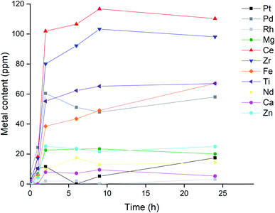
An additional experiment was performed to investigate if the selectivity towards precious metals could be enhanced by tuning the contact time between the ionic liquid and the catalyst. A S/L ratio of 50 mg mL−1 was used since this resulted in high metal concentrations in the leachate, while showing excellent recovery rates for palladium (Table 2). The samples were stirred at 300 rpm at 22.5 °C, periodically the samples were centrifuged for 5 min at 5000 rpm and an aliquot was taken and analyzed as described in the Experimental section. The results for the metal concentrations in the leachate are visualized in Fig. 11.
The strontium concentration was left out of Fig. 11 due to its negligible metal content in the first leachate (Table 2), as this would result in a clearer graph. The influence of trace amounts of strontium on the precious metal leaching was expected to be negligible. The fact that both the precious and base metals all reach their maximum concentration after the same amount of time: 2 hour, is rather peculiar. A possible explanation might be that the metals that are leached by the trichloride species are spread rather thin on the monolith structure, and leaching is not really influenced by the inherent leaching rate for each metal. Another contributing factor might be the high viscosity of the ionic liquids, resulting in a system where the apparent leaching rate is in fact determined by a physical phenomenon like mass transfer. A combination of both factors is also possible.
Whatever the cause, this observation is rather unfavorable as the selectivity towards precious metals cannot be further enhanced by tuning the reaction time between the catalyst powder and the ionic liquid. Nevertheless, the designed system could already leach palladium with greater selectivity: the final concentration of palladium in Fig. 11 (58 ppm) was more than half of that of the most concentrated metal: cerium (110 ppm). This is in sharp contrast to the values reported in Table 1, which list the elemental composition of the catalyst, where certain metals, like magnesium, were about 30 times more abundant than palladium. In the final ionic liquid leachate, the magnesium concentration was a mere third of the palladium concentration, which means that this leaching system increased the Pd/Mg ratio by two orders of magnitude. Therefore, leaching with a trichloride ionic liquid can drastically increase the relative concentration of palladium compared to the other metals, from only a minor element in the catalyst composition, to one of the most abundant elements in the leachate. This demonstrates that the trichloride ionic liquids can be used to increase the selectivity of palladium leaching in exhaust catalysts, reducing the amount of required reagents for the recycling of these valuable metals from end-of-life waste.
Conclusions
Three trihalide ionic liquids, [P66614][Cl3], [P66614][Br3], [P66614][I3], and one mixed trihalide ionic liquid [P66614][IBr2] were prepared from the commercially available Cyphos IL 101 and Cyphos IL 102 ionic liquids. These reactive solvents were used in a series of dissolution experiments, testing the optimal leaching conditions for precious metal wires of platinum, palladium, rhodium and gold. Rhodium and platinum were found to be too unreactive to be leached by any of the tested ionic liquids, even when fine powders with a high surface area were used. When using the trichloride ionic liquid, palladium and gold were leached significantly faster, and further experiments using this ionic liquid were performed (varying conversion ratios of chloride to trichloride and temperature) in order to determine the best leaching conditions. Higher conversions resulted in faster leaching rates, especially for gold. Increasing the leaching temperature could also be used to increase dissolution rates, but Raman spectra showed that this resulted in loss of trichloride anions. This emphasizes the requirements to store the trihalide ionic liquids in cooled environments while shielded from incident light. Afterwards, the ionic liquids were used to selectively leach palladium from real end-of-life waste in the form of spent automotive catalysts. Leaching with trichloride ionic liquids greatly improved to selectivity for palladium. The highest increase in selectivity was observed for palladium compared to magnesium, a metal present in the cordierite catalyst matrix, the relative ratio of Pd/Mg increased over two orders of magnitude in the ionic liquid leachate compared to the elemental composition of the catalyst material.Conflicts of interest
The authors declare no competing financial interest.Acknowledgements
This work has received funding from the European Union's Horizon 2020 Research and Innovation programme under Grant Agreement No. 730224 (PLATIRUS: PLATInum group metals Recovery Using Secondary raw materials) (project website: http://www.platirus.eu/). The authors would like to thank the ‘Agentschap voor Innovatie door Wetenschap en Technologie’ (IWT) for the funding of a PhD grant to A. Van den Bossche (1S04216N). The Research Foundation-Flanders (FWO, grant no. 12X5119N, postdoctoral fellowship to N. Rodriguez Rodriguez) is also acknowledged. The authors acknowledge Monolithos (Athens, Greece) for providing the spent catalysts.References
- G. A. Blengini, C. EL Latunussa, U. Eynard, C. Torres de Matos, D. Wittmer, K. Georgitzikis, C. Pavel, S. Carrara, L. Mancini, M. Unguru, D. Blagoeva, F. Mathieux and D. Penning, Study on the EU’s list of Critical Raw Materials – Final Report, European Commission, Brussels, 2020 Search PubMed.
- Y. Zhang, R. W. Cattrall, I. D. McKelvie and S. D. Kolev, Gold Bull., 2011, 44, 145–153 CrossRef CAS.
- C. Hagelüken, Platinum Met. Rev., 2012, 56, 29–35 CrossRef.
- B. P. Saha, R. Johnson, I. Ganesh, G. V. N. Rao, S. Bhattacharjee and Y. R. Mahajan, Mater. Chem. Phys., 2001, 67, 140–145 CrossRef CAS.
- I. M. Lachman and J. L. Williams, Catal. Today, 1992, 14, 317–329 CrossRef CAS.
- M. Ozawa, J. Alloys Compd., 1998, 275–277, 886–890 CrossRef CAS.
- H. Dong, J. Zhao, J. Chen, Y. Wu and B. Li, Int. J. Miner. Process., 2015, 145, 108–113 CrossRef CAS.
- O. Forsén, J. Aromaa and M. Lundström, Recycling, 2017, 2, 19 CrossRef.
- Z. Peng, Z. Li, X. Lin, H. Tang, L. Ye, Y. Ma, M. Rao, Y. Zhang, G. Li and T. Jiang, JOM, 2017, 69, 1553–1562 CrossRef CAS.
- M. G. Aylmore and D. M. Muir, Miner. Eng., 2001, 14, 135–174 CrossRef CAS.
- S. Ubaldini, P. Fornari, R. Massidda and C. Abbruzzese, Hydrometallurgy, 1998, 48, 113–124 CrossRef CAS.
- E. N. Trifonova, D. V. Drobot and V. A. Krenev, Inorg. Mater., 2003, 39, 529–531 CrossRef CAS.
- A. M. Chekmarev, E. P. Buchikhin, D. S. Sidorov and A. M. Koshcheev, Theor. Found. Chem. Eng., 2007, 41, 752–754 CrossRef CAS.
- A. P. Abbott, R. C. Harris, F. Holyoak, G. Frisch, J. Hartley and G. R. T. Jenkin, Green Chem., 2015, 17, 2172–2179 RSC.
- K. Binnemans and P. T. Jones, J. Sustain. Metall., 2017, 3, 570–600 CrossRef.
- E. N. Trifonova, D. V. Drobot and V. A. Krenev, Inorg. Mater., 2003, 39, 529–531 CrossRef CAS.
- W. Lin, in Noble Metals, ed. Y.-H. Su, InTech, Rijeka, 2012 Search PubMed.
- A. Dadgar, JOM, 1989, 41, 37–41 CrossRef CAS.
- K. Strubbe and W. P. Gomes, J. Electrochem. Soc., 1993, 140, 3294–3300 CrossRef CAS.
- Y. Nakao, J. Chem. Soc., Chem. Commun., 1992, 426–427 RSC.
- R. Jones, B. Wills and C. Kang, West. J. Emerg. Med., 2010, 11, 151–156 Search PubMed.
- H. Haller and S. Riedel, Z. Anorg. Allg. Chem., 2014, 640, 1281–1291 CrossRef CAS.
- T. Welton, Chem. Rev., 1999, 99, 2071–2084 CrossRef CAS PubMed.
- N. V. Plechkova and K. R. Seddon, Chem. Soc. Rev., 2007, 37, 123–150 RSC.
- M. J. Earle, J. M. S. S. Esperança, M. A. Gilea, J. N. C. Lopes, L. P. N. Rebelo, J. W. Magee, K. R. Seddon and J. A. Widegren, Nature, 2006, 439, 831–834 CrossRef CAS PubMed.
- A. Van den Bossche, E. De Witte, W. Dehaen and K. Binnemans, Green Chem., 2018, 20, 3327–3338 RSC.
- P. M. Dean, B. R. Clare, V. Armel, J. M. Pringle, C. M. Forsyth, M. Forsyth and D. R. MacFarlane, Aust. J. Chem., 2009, 62, 334–340 CrossRef CAS.
- R. Cristiano, K. Ma, G. Pottanat and R. G. Weiss, J. Org. Chem., 2009, 74, 9027–9033 CrossRef CAS PubMed.
- J. N. Chubb, P. Lagos and J. Lienlaf, J. Electrost., 2005, 63, 119–127 CrossRef CAS.
- M. Virnig, D. McSweeney and F. McDonnell, US Pat., US 2008/0035893 A1, 2007 Search PubMed.
- Z. Barnea, T. Sachs, M. Chidambaram and Y. Sasson, J. Hazard. Mater., 2013, 244–245, 495–500 CrossRef CAS PubMed.
- X. Li, A. Van den Bossche, T. Vander Hoogerstraete and K. Binnemans, Chem. Commun., 2018, 54, 475–478 RSC.
- X. Li, Z. Li, M. Orefice and K. Binnemans, ACS Sustainable Chem. Eng., 2019, 7, 2578–2584 CrossRef CAS.
- B. May, M. Lexow, N. Taccardi, H.-P. Steinrück and F. Maier, ChemistryOpen, 2019, 8, 15–22 CrossRef CAS PubMed.
- A. P. Abbott, G. Frisch, S. J. Gurman, A. R. Hillman, J. Hartley, F. Holyoak and K. S. Ryder, Chem. Commun., 2011, 47, 10031–10033 RSC.
- I. Yakoumis, A. M. Moschovi, I. Giannopoulou and D. Panias, IOP Conf. Ser.: Mater. Sci. Eng., 2018, 329, 012009 Search PubMed.
- T. Vander Hoogerstraete, S. Jamar, S. Wellens and K. Binnemans, Anal. Chem., 2014, 86, 3931–3938 CrossRef CAS PubMed.
- E. Eyal and A. Treinin, J. Am. Chem. Soc., 1964, 86, 4287–4290 CrossRef CAS.
- T. Vander Hoogerstraete, S. Wellens, K. Verachtert and K. Binnemans, Green Chem., 2013, 15, 919–927 RSC.
- M. Casapu, J.-D. Grunwaldt, M. Maciejewski, M. Wittrock, U. Göbel and A. Baiker, Appl. Catal., B, 2006, 63, 232–242 CrossRef CAS.
- A. K. Upadhyay, J. Lee, E. Kim, M. Kim, B.-S. Kim and V. Kumar, J. Chem. Technol. Biotechnol., 2013, 88, 1991–1999 CAS.
Footnote |
| † Electronic supplementary information (ESI) available: Mass losses, ICP-OES data and limit of detection determination of palladium and rhodium wires. See DOI: 10.1039/d1ra00695a |
| This journal is © The Royal Society of Chemistry 2021 |

![[hexagon filled, point down]](https://www.rsc.org/images/entities/char_e124.gif) ) and Zn (
) and Zn (![[pentagon filled]](https://www.rsc.org/images/entities/char_e13d.gif) ) while leaching catalyst sample in [P66614][Cl3] at ratio of 50 mg mL−1, stirring at 300 rpm at 22.5 °C.
) while leaching catalyst sample in [P66614][Cl3] at ratio of 50 mg mL−1, stirring at 300 rpm at 22.5 °C.