 Open Access Article
Synergistic effect of cocatalytic NiSe2 on stable 1T-MoS2 for hydrogen evolution†
Zhen Lia,
Xinzhi Maa,
Lili Wu *ab,
Hongfeng Yea,
Lu Lia,
Shuangyan Lin
 c,
Xitian Zhang
 a,
Zhitao Shaoa,
Yue Yanga and
Hong Gao
 *a
*a
aKey Laboratory for Photonic and Electronic Bandgap Materials, Ministry of Education, School of Physics and Electronic Engineering, Harbin Normal University, Harbin 150025, China. E-mail: wll790107@hotmail.com; gaohong65cn@126.com
bCenter for Engineering Training and Basic Experimentation, Heilongjiang University of Science and Technology, Harbin 150022, China
cSchool of Chemistry, Guangdong University of Petrochemical Technology, Maoming, Guangdong 525000, PR China
First published on 10th February 2021
Abstract
Robust and economical catalysts are imperative to realize the versatile applications of hydrogen. Herein, a 1T-MoS2/N-doped NiSe2 composite was rationally synthesized via a solvothermal method, in which the MoS2 nanosheets have a stable 1T phase structure, and the NiSe2 nanoparticles serve as a cocatalytic support for MoS2. The nonnegligible electronic couplings between NiSe2 and MoS2 could facilitate the optimization of their electronic structure and then improve the hydrogen adsorption. What is more, the nitrogen dopants in the NiSe2 nanoparticles could intensify the intercalation of ammonium ions in the 1T-MoS2 nanosheets, and further enlarge their interlayer spacing, thus the electrolyte could infiltrate into the catalyst more easily and sufficiently. This work provides a new route for rationally designing highly active and low cost hydrogen evolution reaction (HER) catalysts, and enriches the study of transition metal chalcogenides toward HER.
1. Introduction
Hydrogen is recognized as a promising clean energy resource because of its high gravimetric energy density and no CO2 release.1–4 Among the existing H2 production methods, electrochemical and photocatalytic hydrogen evolution by water splitting have been widely recognized as the most promising strategies.5–7 Especially, electrochemical technology has significant advantages due to its quick, straightforward and highly efficient fashion.8–10 Generally, to achieve a fast H2 production rate, a catalyst with high efficiency is necessary. Up to now, platinum (Pt)-based catalysts have been widely considered as the best catalysts for HER. However, their limitations such as being expensive and having frustrating durability severely restricted their scale-up commercial applications.11–13 Thus, the rational design and fabrication of economic and durable HER catalysts are of great importance.Transition metal dichalcogenides (TMDs) have attracted considerable attention in substituting Pt-based catalysts due to their excellent electrocatalytic properties, popular price, and abundant earth reserves.14 Molybdenum disulfide (MoS2) is one of the most representative TMDs. Notably, the typical lamellar characterizations and structural polymorphism grant it distinctive characteristics in the electrochemical field.15 Generally, MoS2 is in a 2H phase, which is thermodynamically stable. 2H-MoS2 is semiconductor and has a poor conductivity. Besides, the large inert basal planes and small proportion of active edges significantly limits its catalytic efficiency.16,17 In comparison with 2H-MoS2, the metallic (1T) phase MoS2 has a good conductivity and possesses excellent HER response both on basal plane and at edge sites. However, the microstructure of 1T-MoS2 is thermally metastable and would gradually convert into 2H-phase even at room temperature.17 Thus, stable 1T-MoS2 catalysts are highly pursued for the applications in hydrogen evolution. Typically, Wu et al. successfully prepared osmotically swollen MoS2, in which adjacent layers are intercalated by ammonium ions with remarkable lattice expansion. The swollen MoS2 catalyst exhibits excellent HER activity with a small Tafel slope of 45 mV dec−1.18 However, the HER performances are still unsatisfied. Constructing heterogeneous interfaces by introducing another component is an efficient way to boost the electrochemical activity of catalysts.19–23 As is known to all, HER proceeds with the initial formation of hydrogen intermediates (H*) followed by a Tafel or Heyrovsky step. The synergistic effect between two hybridized components could fine tune their surface adsorption properties by interfacial electronic coupling and facilitate an excellent activity and a high stability towards HER. For example, Song et al. bounded 1T-MoS2 nanopatches to highly conductive single-walled carbon nanotube films relying on interface engineering and realized a further improved overpotential of 108 mV.23 Regrettably, the single-walled carbon nanotube films exhibit scarce catalytic activity, and just behave as the conductive skeletons at the expense of the catalyst weight. Recently, the heterogeneous TMDs with a relatively high conductivity are considered to be used as a cocatalytic support for MoS2 due to their excellent cocatalytic functionality.24,25 Typically, Yang' group chose conductive NiS2 to construct 1T-MoS2/NiS2 hybrid catalyst and realized a low onset potential of 34 mV.26 Although extensive efforts have been devoted, the development of heterogeneous TMDs catalyst still lies in its early stage.
In this work, N-doped NiSe2 nanoparticles were selected as the cocatalytic support for 1T-MoS2 nanosheets. The nonnegligible electronic couplings between NiSe2 and MoS2 could facilitate the optimization of their electronic structure and then improve their hydrogen adsorption. In addition, the nitrogen dopants in the NiSe2 nanoparticles could further enlarge the (002) interlayer spacing of MoS2, which makes electrolyte infiltrate into the catalyst more easily and sufficiently. This work enriches the study on heterogeneous TMDs catalyst for HER and provides a new option to realize stable 1T-MoS2.
2. Experimental
2.1 Chemicals and reagents
Nickel chloride hexahydrate (NiCl2·6H2O, 98%), sodium borohydride (NaBH4, 98%), selenium (Se, 99.9%), thiourea (CS(NH2)2, 99%), ammonium molybdate ((NH4)6Mo7O24·4H2O, 99%), disodium hydrogen phosphate dodecahydrate (Na2HPO4·7H2O), sodium phosphate monobasic dihydrate (NaH2PO4·2H2O) are all analytical grade. They were used without further purification.2.2 Materials syntheses
Bare NiSe2 nanoparticles were synthesized by solvothermal method. First, 0.316 g selenium and 0.189 g NaBH4 were dissolved in 30 mL N,N-dimethylformamide (DMF) and stirred for 1 hour. Then, 0.476 g NiCl2·6H2O was gradually added into the solution and agitated for 1 hour. After that, the solution was poured into a Teflon-lined autoclave, whose volume is 50 mL. The autoclave was kept at 160 °C for 12 hours. Centrifugal method was adopted to gather the precipitate. Deionized water and ethanol were alternatively used as cleaning fluid. Finally, the collected precipitate was dried at 60 °C in vacuum overnight.To synthesize MoS2/NiSe2 composite, 76 mg of as-prepared NiSe2 powder was dispersed in 30 mL deionized water and sonicated for 30 min. Then 62 mg (NH4)6Mo7O24·4H2O and 114 mg CS(NH2)2 were added into the solution and stirred homogeneously. The dispersion was kept at 180 °C for 24 hours. The collection and treatment of the precipitate are the same as above.
The synthesis of bare MoS2 nanosheets is the same as that for MoS2/NiSe2 composite expect for adding NiSe2 nanoparticles as substrates.
2.3 Fabrication of electrodes
The prepared catalysts and carbon nanotubes were dispersed in the solvent of N-methyl-2-pyrrolidone (NMP) including 7 wt% PVDF (mass ratio of catalysts, PVDF, and carbon nanotubes was 8![[thin space (1/6-em)]](https://www.rsc.org/images/entities/char_2009.gif) :
:![[thin space (1/6-em)]](https://www.rsc.org/images/entities/char_2009.gif) 1
1![[thin space (1/6-em)]](https://www.rsc.org/images/entities/char_2009.gif) :
:![[thin space (1/6-em)]](https://www.rsc.org/images/entities/char_2009.gif) 1). After ultrasonic uniformity, the slurry was coated on carbon paper (mass loading: 1 mg cm−2), and dried at 60 °C for 12 h under vacuum condition.
1). After ultrasonic uniformity, the slurry was coated on carbon paper (mass loading: 1 mg cm−2), and dried at 60 °C for 12 h under vacuum condition.
2.4 Materials characterization
The crystal structure was characterized by X-ray diffraction (XRD, D/max 2600, Rigaku, Japan) with Cu Kα radiation (λ = 1.5418 Å). The micromorphology and elementary composition were determined by scanning electron microscopy (SEM, SU70, Hitachi, Japan) equipped with energy dispersive X-ray spectroscopy (EDS) and transmission electron microscopy (TEM, FEI, Tecnai TF20). The surface chemical states were characterized by X-ray photoelectron spectroscopy (XPS) employing K-alpha X-ray spectrometer (Thermo, USA).2.5 Electrocatalytic measurements
The VMP3 electrochemical workstation (Bio-logic, France) was used to conduct electrochemical measurements. The experiments were carried out within a typical three-electrode system in 0.5 M H2SO4 electrolyte (except where noted). The prepared catalysts coated on carbon paper was used as working electrode with saturated calomel electrode (SCE) and carbon rod as reference and counter electrodes, respectively. The formula E (RHE) = E (SCE) + 0.059 × pH + 0.241 V was used to convert potentials into the reversible hydrogen electrode defined as (RHE). Polarization curves were attained using a linear sweep voltammetry (LSV) method. All the polarization curves were corrected using 85% ohmic potential drop (iR) compensation. The electrochemical impedance spectroscopy (EIS) was measured at the overpotential of −0.2 V (vs. RHE) with the frequencies ranging from 100 mHz to 100 KHz. Electrochemical surface area (ECSA) was estimated by the cyclic voltammetry (CV) measurements at 20–100 mV s−1. By plotting the different scan rate of anode and cathode current density difference (Δj = ja − jc) at 0.15 V (vs. RHE), double-layer capacitance (Cdl) is defined as half of the slopes value. Turnover frequency (TOF) of the catalysts was calculated by employing the CV curves measured in pH = 7 phosphate buffer. The voltage range is from −0.2 to 0.6 V (vs. RHE), and the scan rate is 50 mV s−1. The calculation follows the equation: TOF (s−1) = (j × A)/(2 × n × F), where F is the Faraday's constant (96![[thin space (1/6-em)]](https://www.rsc.org/images/entities/char_2009.gif) 485 C mol−1), j (mA cm−2) is the current density obtained by LSV measurement, A (cm2) is the geometric area of the electrodes, and the number of 2 represents that two electrons are required to form one hydrogen molecule from two protons (2H+ + 2e− = H2). Catalytic stability was examined by the CV test at 50 mV s−1 from −0.3 to 0.1 V (vs. RHE) and the chronoamperometry measurement at −100 mV (vs. RHE) for 25 h.
485 C mol−1), j (mA cm−2) is the current density obtained by LSV measurement, A (cm2) is the geometric area of the electrodes, and the number of 2 represents that two electrons are required to form one hydrogen molecule from two protons (2H+ + 2e− = H2). Catalytic stability was examined by the CV test at 50 mV s−1 from −0.3 to 0.1 V (vs. RHE) and the chronoamperometry measurement at −100 mV (vs. RHE) for 25 h.
3. Results and discussion
3.1 Morphologies and structures
Fig. 1a illustrates the preparation process of MoS2/NiSe2 composite. Firstly, NiSe2 nanoparticles were prepared via a solvothermal method. The SEM image in Fig. S1† well exhibits their irregular polyhedral morphology with a large amount of ridges and re-entrants. EDS analysis reveals that the as-prepared nanoparticles are slightly nonstoichiometric NiSe2 with a small amount of nitrogen dopant (Fig. S2†). Secondly, the N-doped NiSe2 nanoparticles were dispersed into a homogeneous aqueous solution of ammonium molybdate and thiourea to in situ grow MoS2 nanosheets on their surface. The resultant compositions were firstly characterized by XRD. In Fig. 1b, the XRD profile consists of dominant sharp diffraction peaks of cubic NiSe2 (JCPDS 88-1711) and faint signals of MoS2. Notably, the (002) peak of MoS2 is located at 8.7°, which shows a remarkable negative shift from the (002) peak of 2H-phase MoS2 (JCPDS 37-1492), demonstrating that the MoS2 nanosheets have a 1T-phase structure and the resultant products are 1T-MoS2/N-doped NiSe2 composite. The bare MoS2 nanosheets prepared without N-doped NiSe2 nanoparticles participating also have a 1T-phase structure with their (002) peak located at 9.1°. It powerfully indicates that the MoS2 synthesized in this study, either bare or in composite, are both in 1T phase. More importantly, the 1T-MoS2 is thermodynamically stable, which is proved by almost the same XRD pattern obtained from the sample aged 3 months at room temperature (Fig. S3†).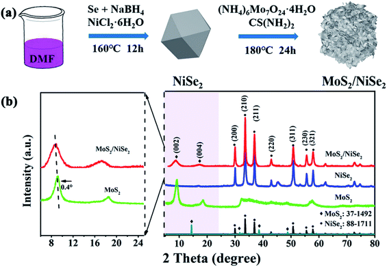 | ||
| Fig. 1 (a) Diagrammatic drawing of the synthesis process of MoS2/NiSe2 composite, in which DMF stands for N,N-dimethylformamide. (b) XRD patterns of bare MoS2, NiSe2, and MoS2/NiSe2 composite. | ||
The morphology of the 1T-MoS2/N-doped NiSe2 composite was vividly shown in Fig. 2a. It is clear that a sight of flimsier nanosheets intertwine into an edge-oriented geometry on the outer surface of N-doped NiSe2 nanoparticles. The nanosheets distribute more homogeneously than those ones prepared without N-doped NiSe2 nanoparticles participating (Fig. S4†). It should give the credit of this homogeneous distribution to the abundant and highly dispersed nucleation sites provided by the N-doped NiSe2 nanoparticles. EDS analysis reveals that S, Mo, Se and Ni elements coexist in the composite with a small amount (∼6.7 at%) of N element (inset of Fig. 2a), which should be inherited from DMF, thiourea and ammonium molybdate. The elemental mappings in Fig. 2b demonstrate the uniformly dispersion of Ni, Se, Mo, S, and N. The luminosities of Ni, Se, Mo and S elements are markedly higher than that of N element, illustrating the relatively low content of N element. The distributions of Mo and S have a slightly larger size than those of Ni and Se, corresponding to the decoration of NiSe2 nanoparticles with the MoS2 nanosheets. The further microstructural information of the 1T-MoS2/N-doped NiSe2 composite was characterized by TEM. Fig. 2c shows that the composite consists of internal NiSe2 nanoparticle (dark area) and external translucent MoS2 nanosheets. The ultrathin MoS2 nanosheets are less than five layers and tightly wrap the NiSe2 nanoparticle, which generates abundant interfaces between MoS2 and NiSe2. The typical high-resolution TEM image offers a deep insight to these heterogeneous interfaces (Fig. 2d). The lattice distance of 0.27 nm is assigned to the (210) plane of NiSe2, and the one of 1.02 nm is the (002) plane of 1T-MoS2.27,28 Impressively, the (002) lattice distance of 1.02 nm for 1T-MoS2 is 0.4 nm larger than 2H-MoS2 (∼0.62 nm), and coincides with the diffraction peak located at 8.7° in the XRD curve (Fig. 1b). This increment just well accommodate ammonium ions, whose size is about 0.35 nm.29,30 Thus, the enlarged (002) interlayer spacing of MoS2 in this study should owe to the intercalation of ammonium ions inherited from thiourea or ammonium molybdate. Fig. S5† is the high-resolution TEM image of bare MoS2 nanosheets. It is noticeable that the (002) interlayer spacing of the MoS2 in composite is further enlarged with a ∼5% expansion by hybridizing with N-doped NiSe2 nanoparticles. Fig. 2e shows the SAED pattern of the 1T-MoS2/N-doped NiSe2 composite, wherein the (110) and (105) planes belong to 1T-MoS2, and the (200), (210), (211) and (220) planes belong to N-doped NiSe2. The discrete concentric rings well demonstrate the polycrystalline nature of the 1T-MoS2/N-doped NiSe2 composite.
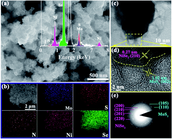 | ||
| Fig. 2 (a) SEM image, inset shows the relevant EDS spectrum, (b) the corresponding elemental mapping images, (c) TEM image, (d) HRTEM image, and (e) SAED pattern of MoS2/NiSe2 composite. | ||
The compositions and chemical surface states of 1T-MoS2/N-doped NiSe2 composite were analyzed by XPS. Fig. 3a indicates the existence of Ni, Se, Mo, S, and N. Fig. 3b shows the Mo-3d spectra, in which Mo4+, Mo5+, and Mo6+ were included. The peak located at 235.7 eV is corresponding to Mo6+, which is derived from surface oxidation and coincided with the detected O element in Fig. 3a. The two doublets located at 232.5/229.5 eV and 231.6/228.5 eV coincide with the 3d3/2 and 3d5/2 orbits of Mo4+ and Mo5+, respectively.31 In the S-2p spectra (Fig. 3c), the 161.2 eV and 162.5 eV peaks belong to the S2− 2p3/2 and S2− 2p1/2 orbits, respectively.32,33 Compared with bare 1T-MoS2, these peaks all exhibit a red shift in the 1T-MoS2/N-doped NiSe2 composite. Fig. 3d shows the Ni-2p profiles, in which the peaks were divided into three doublet peaks corresponding to Ni2+, Ni3+ and shakeup satellite. The doublets located at 853.6/871.0 eV and 856.4/874.2 eV are corresponded well with the 2p3/2 and 2p1/2 of Ni2+ and Ni3+, and another doublets belong to the shakeup satellite of Ni 2p.27,34 In contrast with the red shifts of Mo-3d and S-2p, the three doublets of Ni-2p all show a blue shift as compared with bare NiSe2. Fig. 3e is the Se-3d XPS spectra. The Se22− 3d5/2 and Se22− 3d3/2 peaks located at 54.7 and 55.6 eV also show a slightly red shifting compared with bare NiSe2.35 These red/blue shifts imply the electron transfer between NiSe2 and MoS2 at their heterogeneous interfaces and highly enhance the hydrogen adsorption ability.23,36,37 Additionally, the ratio of Ni2+/Ni3+ in the composite is 0.56, which significantly larger than that in the bare NiSe2 (0.37). Higher Ni2+/Ni3+ ratio always associates with a superior HER activity due to the higher sensitivity of Ni2+ to HER than Ni3+.38 In Fig. 3f, the N 1s XPS spectra consist of three overlapping peaks. The dominant one is located at 399.4 eV and ascribed to N–Ni bond.39 The nanoid one at 398.2 eV belongs to N–Mo bond.40 The significantly higher intensity of N–Ni than N–Mo bond indicates the relatively higher content of N in NiSe2 than MoS2, which might be the reason why the (002) interlayer spacing of 1T-MoS2 is further enlarged after hybridizing with the N-doped NiSe2 nanoparticles. The small peak located at 401.7 eV is corresponded to the NH4+ embed in the (002) interlayer of MoS2 or located on the surface of NiSe2, strongly supporting the above assertion that the expanded (002) interlayer spacing is realized by the intercalation of ammonium ions.
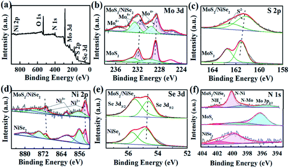 | ||
| Fig. 3 (a) The survey XPS spectrum of MoS2/NiSe2, (b) Mo 3d, (c) S 2p, (d) Ni 2p, (e) Se 3d, (f) N 1s XPS spectra of MoS2/NiSe2 compared with bare MoS2 or NiSe2. | ||
3.2 Electrochemical performances
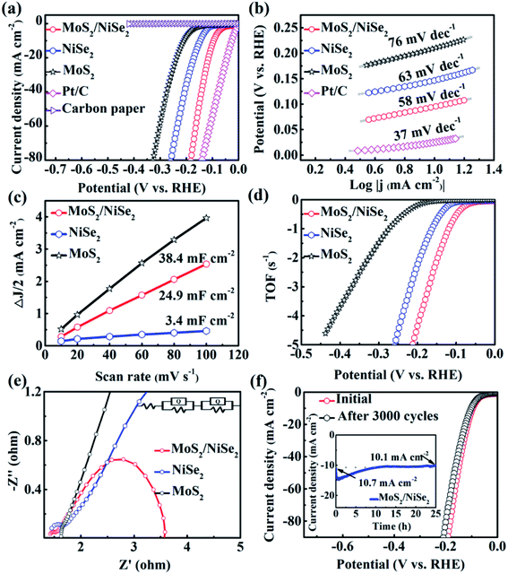
The polarization curve of 1T-MoS2/N-doped NiSe2 composite is shown in Fig. 4a. When current density arrives at 10 mA cm−2, the overpotential is only 94 mV, dramatically surpassing bare MoS2 (210 mV) and NiSe2 (147 mV). In Fig. 4b, the 1T-MoS2/N doped NiSe2 composite, bare MoS2 nanosheets, and NiSe2 nanoparticles exhibit a Tafel slope of 58, 76 and 63 mV dec−1, respectively. They are all larger than 40 mV dec−1, implying a Volmer–Heyrovsky mechanism and the rate-determining step of desorption process. Meanwhile, the lower value of 1T-MoS2/N-doped NiSe2 composite indicates its faster HER kinetics than bare MoS2 and NiSe2.25 More than that, the excellent HER activity and low Tafel slope of 1T-MoS2/N-doped NiSe2 composite also have obvious advantages to most recently reported low-cost HER catalysts (Table S1†). From Tafel data, the exchange current density (j0) of 240.5 μA cm−2 is obtained for 1T-MoS2/N-doped NiSe2 composite. It is significantly larger than that of bare NiSe2 (177.6 μA cm−2) and 1T-MoS2 (17.4 μA cm−2). In Fig. 4c, the Cdl value of 1T-MoS2/N-doped NiSe2 composite is derived from the CV curves in Fig. S6† and calculated to be 24.9 mF cm−2. It is much larger than that of NiSe2 (3.4 mF cm−2) but slightly smaller than MoS2 (38.4 mF cm−2). Therefore, the enhanced HER activity of the composite must not mainly originate from high effective active area.41 TOF is another important parameter for HER catalysts.42 As shown in Fig. 4d and S7,† the composite needs 147 mV overpotential to reach a TOF value of 2 s−1, while bare NiSe2 and MoS2 need an overpotential of 193 and 325 mV, respectively. It suggests that the inherent activity of bare NiSe2 and MoS2 have been dramatically enhanced by forming hybridized composite. This phenomenon can be related to the emergence of the large amount of interfaces between NiSe2 and MoS2.43 The nonnegligible electronic coupling generated at these heterogeneous interfaces would result in the enhanced H-chemisorption and thus highly optimize the electrocatalytic activity in the HER. The EIS tests were conducted to analyze the intrinsic conductivity and kinetics of the catalysts. Fig. 4e shows the Nyquist plots of these catalysts at −0.2 V. The high-frequency intersection with the x-axis on the Nyquist plot represents the ohmic resistance (Rs), which expresses the overall interfacial contacts and the resistance of the electrolyte. The smallest Rs of the three catalysts indicates the strong interfacial contacts of 1T-MoS2/N-doped NiSe2 composite. The high-frequency half-arc is associated with the charge transfer resistance (Rct). According to the equivalent circuit (inset in Fig. 4e), the 1T-MoS2/N-doped NiSe2 composite expresses a smaller Rct of 0.25 Ω than bare NiSe2 (0.37 Ω) and MoS2 (0.55 Ω). The low-frequency semicircle represents the mass transfer resistance (Rmt). The mass transfer ability of 1T-MoS2/N-doped NiSe2 composite is also superior to the other two catalysts. These improvements after hybridizing should be attributed to the nonnegligible electronic couplings between NiSe2 and MoS2, the superior conductivity of NiSe2 and the homogeneous distribution and further enlarged (002) interlayer spacing of 1T-MoS2.The durability of 1T-MoS2/N-doped NiSe2 composite was evaluated by 3000 times CV sweeping at 50 mV s−1. In Fig. 4f, the polarization curve just exhibits an inappreciable decline after cycling. From another point of view, when 100 mV overpotential was applied, the current density decreases only 0.6 mA cm−2 after a chronoamperometric process for 25 hours (Inset of Fig. 4f). In Fig. S8,† the cycled 1T-MoS2/N-doped NiSe2 composite shows a similar morphology with the fresh composite in Fig. 2a. The structural information was also characterized by XRD test (Fig. S9†). The (002) peak of 1T-MoS2 is still located at 8.7°, strongly confirming the robust microstructural stability of our 1T-MoS2 as well as the 1T-MoS2/N-doped NiSe2 composite. The cycled composite was further analyzed by XPS. Fig. 5a manifests that all the elements of Mo, S, Ni, Se and N are maintained. In Fig. 5b–f, the same compositions and chemical surface states are shown as the profiles in Fig. 3. Especially, the proportion of NH4+ in the N 1s XPS spectrum is kept well after cycling (Fig. 5f), powerfully solidifying the structural stability of the 1T-MoS2 synthesized in this study once again. Based on above analysis, it is reasonable to conclude that the 1T-MoS2/N-doped NiSe2 composite can afford the catalytic process for a long time, and its morphology, microstructure, and compositions can be kept well after the durability test.
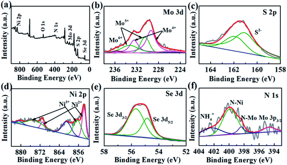 | ||
| Fig. 5 (a) The survey, (b) Mo 3d, (c) S 2p, (d) Ni 2p, (e) Se 3d, (f) N 1s XPS spectra of MoS2/NiSe2 composite after cycling measurement. | ||
4. Conclusions
In summary, 1T-MoS2/N-doped NiSe2 composite has been successfully fabricated via a solvothermal method. The composite achieves a 94 mV overpotential at 10 mA cm−2, a small Tafel slope of 58 mV dec−1 and a good cycling durability in an acidic situation. Such promising HER performances should be attributed to: (i) the abundant exposed active edge sites arose from the ultrasmall size as well as the highly dispersed geometry of 1T-MoS2 nanosheets; (ii) the intercalation of ammonium ions and further widened interplanar distance of 1T-MoS2, which make electrolyte infiltrate into the catalyst more easily and sufficiently; (iii) the cocatalytic support of NiSe2, which not only provides a conductive support to the 1T-MoS2 nanosheets, but also serves as a cocatalyst for HER; (iv) the abundant interfaces with nonnegligible electronic coupling/interactions between MoS2 and NiSe2, which could facilitate the optimization of their electronic structure and then improve hydrogen adsorption. Given the above, this study offers a new option to realize stable 1T-MoS2 and design efficient and low cost HER catalysts.Conflicts of interest
The authors declare no competing financial interest.Acknowledgements
This work was partially supported by the National Natural Science Foundation of China (No. 11504097, 51772069), and the Fundamental Research Funds for the Provincial Universities of Heilongjiang (Wu Li Li).References
- Q. Liu, Z. Xue, B. Jia, Q. Liu, K. Liu, Y. Lin, M. Liu, Y. Li and G. Li, Small, 2020, 16, 2002482 CrossRef CAS.
- M. He, F. Kong, G. Yin, Z. Lv, X. Sun, H. Shi and B. Gao, RSC Adv., 2018, 8, 14369–14376 RSC.
- H. Wang, X. Xiao, S. Liu, C. L. Chiang, X. Kuai, C. K. Peng, Y. C. Lin, X. Meng, J. Zhao, J. Choi, Y. G. Lin, J. M. Lee and L. Gao, J. Am. Chem. Soc., 2019, 141, 18578–18584 CrossRef CAS.
- J. Huang, D. Hou, Y. Zhou, W. Zhou, G. Li, Z. Tang, L. Li and S. Chen, J. Mater. Chem. A, 2015, 3, 22886–22891 RSC.
- K. Reilly, B. Fang, F. Taghipour and D. P. Wilkinson, ACS Appl. Energy Mater., 2020, 3, 8317–8329 CrossRef CAS.
- G. Liao, J. Fang, Q. Li, S. Li, Z. Xu and B. Fang, Nanoscale, 2019, 11, 7062–7096 RSC.
- G. Liao, Y. Gong, L. Zhang, H. Gao, G. J. Yang and B. Fang, Energy Environ. Sci., 2019, 12, 2080–2147 RSC.
- J. Zhang, T. Wang, D. Pohl, B. Rellinghaus, R. Dong, S. Liu, X. Zhuang and X. Feng, Angew. Chem., 2016, 128, 6814–6819 CrossRef.
- Y. Li, H. Wang, L. Xie, Y. Liang, G. Hong and H. Dai, J. Am. Chem. Soc., 2011, 133, 7296–7299 CrossRef CAS.
- J. Greeley, T. F. Jaramillo, J. Bonde, I. Chorkendorff and J. K. Norskov, Nat. Mater., 2006, 5, 909–913 CrossRef CAS.
- Y. Guo, T. Park, J. W. Yi, J. Henzie, J. Kim, Z. Wang, B. Jiang, Y. Bando, Y. Sugahara, J. Tang and Y. Yamauchi, Adv. Mater., 2019, 31, 1807134 CrossRef.
- J. E. Lee, J. Jung, T. Y. Ko, S. Kim, S. I. Kim, J. Nah, S. Ryu, K. T. Nam and M. H. Lee, RSC Adv., 2017, 7, 5480–5487 RSC.
- J. Xie, H. Zhang, S. Li, R. Wang, X. Sun, M. Zhou, J. Zhou, X. W. Lou and Y. Xie, Adv. Mater., 2013, 40, 5807–5813 CrossRef.
- D. Wang, D. Zhang, C. Tang, P. Zhou, Z. Wu and B. Fang, Catal. Sci. Technol., 2016, 6, 1952–1956 RSC.
- D. Wang, Y. Xiao, X. Luo, Z. Wu, Y. J. Wang and B. Fang, ACS Sustainable Chem. Eng., 2017, 5, 2509–2515 CrossRef CAS.
- M. A. Lukowski, A. S. Daniel, F. Meng, A. Forticaux, L. Li and S. Jin, J. Am. Chem. Soc., 2013, 135, 10274–10277 CrossRef CAS.
- Z. He and W. Que, Appl. Mater. Today, 2016, 3, 23–56 CrossRef.
- Z. Wu, C. Tang, P. Zhou, Z. Liu, Y. Xu, D. Wang and B. Fang, J. Mater. Chem. A, 2015, 3, 13050–13056 RSC.
- G. Suo, D. Li, L. Feng, X. Hou, X. Ye, L. Zhang, Q. Yu, Y. Yang and W. Wang, J. Mater. Sci. Technol., 2020, 55, 167–172 CrossRef.
- D. Li, J. Zhang, S. M. Ahmed, G. Suo, W. Wang, L. Feng, X. Hou, Y. Yang, X. Ye and L. Zhang, J. Colloid Interface Sci., 2020, 8, 174–181 CrossRef.
- G. Suo, J. Zhang, D. Li, Q. Yu, M. He, L. Feng, X. Hou, Y. Yang, X. Ye, L. Zhang and W. Wang, J. Colloid Interface Sci., 2020, 566, 427–433 CrossRef CAS.
- G. Suo, J. Zhang, D. Li, Q. Yu, W. Wang, M. He, L. Feng, X. Hou, Y. Yang, X. Ye and L. Zhang, Chem. Eng. J., 2020, 388, 124396 CrossRef CAS.
- Q. Liu, Q. Fang, W. Chu, Y. Wan, X. Li, W. Xu, M. Habib, S. Tao, Y. Zhou, D. Liu, T. Xiang, A. Khalil, X. Wu, M. Chhowalla, P. M. Ajayan and L. Song, Chem. Mater., 2017, 29, 4738–4744 CrossRef CAS.
- M. R. Gao, J. X. Liang, Y. R. Zheng, Y. F. Xu, J. Jiang, Q. Gao, J. Li and S. H. Yu, Nat. Commun., 2015, 6, 5982 CrossRef CAS.
- J. Lin, P. Wang, H. Wang, C. Li, X. Si, J. Qi, J. Cao, Z. Zhong, W. Fei and J. Feng, Adv. Sci., 2019, 6, 1900246 CrossRef.
- X. Chen, Z. Wang, Y. Wei, X. Zhang, Q. Zhang, L. Gu, L. Zhang, N. Yang and R. Yu, Angew. Chem., Int. Ed., 2019, 58, 17621–17624 CrossRef CAS.
- B. Yu, X. Wang, F. Qi, B. Zheng, J. He, J. Lin, W. Zhang, Y. Li and Y. Chen, ACS Appl. Mater. Interfaces, 2017, 9, 7154–7159 CrossRef CAS.
- Q. Liu, X. Li, Q. He, A. Khalil, D. Liu, T. Xiang, X. Wu and L. Song, Small, 2015, 11, 5556–5564 CrossRef CAS.
- Y. J. Tang, Y. Wang, X. L. Wang, S. L. Li, W. Huang, L. Z. Dong, C. H. Liu, Y. F. Li and Y. Q. Lan, Adv. Energy Mater., 2016, 6, 1600116 CrossRef.
- R. Zhang, W. Wan, D. Li, F. Dong and Y. Zhou, Chin. J. Catal., 2017, 38, 313–320 CrossRef CAS.
- A. Long, W. Li, M. Zhou, W. Gao, B. Liu, J. Wei, X. Zhang, H. Liu, Y. Liu and X. Zeng, J. Mater. Chem. A, 2019, 7, 21514–21522 RSC.
- G. M. Bremmer, L. V. Haandel, E. J. M. Hensen, J. W. M. Frenken and P. J. Kooyman, Appl. Catal., B, 2019, 243, 145–150 CrossRef CAS.
- B. Tang, Z. G. Yu, Y. Zhang, C. Tang, H. L. Seng, Z. W. Seh, Y. W. Zhang, S. J. Pennycook, H. Gong and W. Yang, J. Mater. Chem. A, 2019, 7, 13339–13346 RSC.
- T. Kou, T. Smart, B. Yao, I. Chen, D. Thota, Y. Ping and Y. Li, Adv. Energy Mater., 2018, 8, 1703538 CrossRef.
- W. Li, B. Yu, Y. Hu, X. Wang, D. Yang and Y. Chen, ACS Sustainable Chem. Eng., 2019, 7, 4351–4359 CrossRef CAS.
- J. Zhu, Z. C. Wang, H. Dai, Q. Wang, R. Yang, H. Yu, M. Liao, J. Zhang, W. Chen, Z. Wei, N. Li, L. Du, D. Shi, W. Wang, L. Zhang, Y. Jiang and G. Zhang, Nat. Commun., 2019, 10, 1348 CrossRef.
- J. Chen, X. J. Wu, Y. Gong, Y. Zhu, Z. Yang, B. Li, Q. Lu, Y. Yu, S. Han, Z. Zhang, Y. Zong, Y. Han, L. Gu and H. Zhang, J. Am. Chem. Soc., 2017, 139, 8653–8660 CrossRef CAS.
- C. Liu, T. Gong, J. Zhang, X. Zheng, J. Mao, H. Liu, Y. Li and Q. Hao, Appl. Catal., B, 2020, 262, 118245 CrossRef CAS.
- S. Han, Y. Hao, Z. Guo, D. Yu, H. Huang, F. Hu, L. Li, H. Y. Chen and S. Peng, Chem. Eng. J., 2020, 401, 126088 CrossRef CAS.
- Y. Yi, Z. Sun, C. Li, Z. Tian, C. Lu, Y. Shao, J. Li, J. Sun and Z. Liu, Adv. Funct. Mater., 2020, 30, 1903878 CrossRef CAS.
- B. Zhang, J. Liu, J. Wang, Y. Ruan, X. Ji, K. Xu, C. Chen, H. Wan, L. Miao and J. Jiang, Nano Energy, 2017, 37, 74–80 CrossRef CAS.
- J. Kibsgaard and T. F. Jaramillo, Angew. Chem., Int. Ed., 2014, 53, 14433–14437 CrossRef CAS.
- C. Tsai, F. A. Pedersen and J. K. Nørskov, Nano Lett., 2014, 14, 1381–1387 CrossRef CAS.
Footnote |
| † Electronic supplementary information (ESI) available. See DOI: 10.1039/d1ra00506e |
| This journal is © The Royal Society of Chemistry 2021 |

