DOI:
10.1039/D1RA00300C
(Paper)
RSC Adv., 2021,
11, 10951-10961
Structure-modulated CaFe-LDHs with superior simultaneous removal of deleterious anions and corrosion protection of steel rebar†
Received
13th January 2021
, Accepted 10th March 2021
First published on 16th March 2021
Abstract
The three anionic species; chloride (Cl−), sulfate (SO42−), and carbonate (CO32−), are typical chemical factors that environmentally accelerate failure of concrete structures with steel rebar through long-term exposure. Efficient removal of these deleterious anions at the early stage of penetration is crucial to enhance the lifespan and durability of concrete structures. Here, we synthesize CaFe-layered double hydroxide (CaFe-LDHs) by a simple one-step co-precipitation technique and structural modulation by calcination process. It is applied for the removal of Cl−, SO42−, and CO32− anions as well as corrosion inhibition on steel rebar in aqueous solutions. The synthesized CaFe-LDHs with phase transfer show notable improvement of removal capacity (Qmax) toward Cl− and SO42− over 3.4 times and over 5.69 times, respectably, then those of previous literatures. Furthermore, the steel rebar exposed to an aqueous solution containing the three anionic sources shows a fast corrosion rate (1876.56 × 10−3 mm per year), which can be remarkably inhibited showing 98.83% of corrosion inhibition efficiency when it is surrounded by those CaFe-LDHs. The novel adsorption mechanisms of these CaFe-LDHs-induced crystals and corresponding corrosion protection properties are elucidated drawing on synergy of memory effects and chemical reactions.
1. Introduction
Building in concrete structures with steel rebar was a remarkable innovation in the construction industry because it adds strength to concrete, providing durability and allowing more specialized designs.1 However, it is always exposed to corrosion, leading to deterioration in concrete structures, which determines their durability and life span, particularly in natural environments.2,3 In general, concrete structures present good durability to corrosion because the structure of concrete presents high alkalinity in the pores of the surrounding concrete, forming a protective, passive layer on the surface of the steel rebar.4–6 Nevertheless, corrosion of steel rebar can be readily initiated when passivity is compromised by damage7 or when the bond between concrete and steel rebar is destroyed by anionic species. Three major anions from different sources are particularly harmful: chloride (Cl−), sulfate (SO42−), and carbonate (CO32−) anions.8 Corrosion is generally initiated by electrochemical flow of electrons and ions.9,10
Penetration of Cl− anions to reinforced concrete is significantly detrimental, especially for structures near marine environments exposed to high concentrations of salts.11,12 In this case, the Cl− anion can easily penetrate concrete structures through capillary adsorption, hydrostatic pressure, or diffusion, accelerating steel rebar corrosion (eqn (1)).13,14 It can penetrate into concrete in diverse forms drawing on the chemical sources of SO42− anions from the environment, which also promotes corrosion of steel rebar in concrete.15 SO42− anion attack occurs by diverse forms drawing on chemical sources, including seawater, acid rain, or combustion gas from industry, leading to destruction of the original properties of concreate (eqn (2)).16–18 Carbonation occurs by CO32− anions, which originate from carbon dioxide, diffusing into the concrete matrix from the air, reacting with calcium hydroxide to form calcium carbonate. This lowers pH and causes general internal volume expansion in the concentrate. When the concrete is neutralized and water and air infiltrate, the corrosion of steel and the volume expands, causing cracks in the concrete cover, resulting in loss of the strength and durability of the structure (eqn (3)).19 This deteriorates the life-span of the concrete structures by providing easy penetration paths for other corrosion species.
| | |
Fe2+ + 2Cl− → FeCl2 + 2e−
| (1) |
| | |
2Fe + 2H2SO4 + O2 → 2FeSO4 + 2H2O
| (2) |
| | |
Ca(OH)2 + CO2 → CaCO3 + H2O
| (3) |
Deterioration in performance or structural damage of reinforced concrete structures not only adversely affects safety, but also causes enormous losses to society and the national economy over a long period of time.20,21 Therefore, it is necessary to selectively and promptly remove deleterious anions as soon as they penetrate the concrete structure to maintain durability and life span.
Layered double hydroxides (LDHs) are hydrotalcite-like compounds with high specific surface area, memory effects, eco-friendly features, and low-cost, widening utilization in the fields of hazardous materials adsorption, catalysts, biomedicine, agriculture, and wastewater treatment.22–25 The general formula of LDHs is [M1−x2+Mx3+(OH)2]x+[An−]x/n·yH2O, where M2+ includes Ca, Mg, Zn, Co, Ni, and Cu, and M3+ includes Fe, Al, and Cr. LDHs are composed of positively charged layers with divalent and trivalent metal cations, and interlayer anions (An−) is a negatively charged anion layer. The layer structures of positive charges are balanced by the An−, which are exchangeable with other anionic species in aqueous solutions.26 In addition, the crystallinity of LDHs can typically be transformed into their respective metal oxides by calcining at temperatures in the range of 400 to 700 °C. As a consequence, water in the crystals, hydroxyl groups of LDHs, and intercalated anions are completely removed, leaving behind mixed metal oxides. It is a unique property of LDH that it recovers its original structure after calcination followed by reconstruction via the memory effect.27,28 Compared to most frequently used MgAl-based LDHs (MgAl-LDHs), CaFe-based LDHs (CaFe-LDHs) are synthesized in a cost-effective way by co-precipitation at room temperature without increasing the reaction temperature.29,30 Although much work has been reported on the corrosion inhibitive effects of LDHs,31–34 the influence of co-existing Cl−, SO42−, and CO32− anions on the corrosion protection ability of LDHs has not been considered. Moreover, few studies have investigated the anion adsorption mechanisms of CaFe-based LDHs and their potential for corrosion resistant property.
In this study, we report a synthesis of CaFe-LDHs and CaFe-based metal oxides by a modified one-step co-precipitation method follow by structural modulation. The removal performance of harmful anionic species including Cl−, SO42−, and CO32− are studied in an aqueous solution containing the nanopowders, initiated by the CaFe-LDHs. The corrosion protection efficiency of steel rebar for the potential improvement of the durability of concrete structures is envisaged relying on structural variation of the CaFe-LDHs. The mechanisms for simultaneous capturing of anion species and anti-corrosion are investigated with respect to phase transfer of CaFe-LDHs drawing on the variation of crystallinity coupled with stoichiometry.
2. Experimental
2.1. Materials and reagents
Reagents were prepared using calcium nitrate tetrahydrate (Ca(NO3)2·4H2O, 99%), iron nitrate nonahydrate (Fe(NO3)3·9H2O, 98%), sodium hydroxide (NaOH, 99%), sodium chloride (NaCl, 99.5%), sodium sulphate (Na2SO4, 99%), and sodium carbonate (Na2CO3, 99.5%). All were used as-purchased from Sigma-Aldrich, Inc. Daejung, Inc. without further purification. Distilled deionized water was used for preparation of aqueous standard ionic solutions.
2.2. Synthesis of CaFe-LDHs
CaFe-LDHs, which were previously prepared by a typical co-precipitation method,30,35,36 were prepared via a modified method here. Specifically, CaFe-LDH was prepared by one-step synthesis of co-precipitation of two precursor materials, an aqueous solution containing 3 M NaOH (900 mL) was rapidly injected into the second solution (900 mL) containing a mixture of 66.7 mmol of Ca(NO3)2·4H2O and 33.3 mmol of Fe(NO3)3·9H2O at room temperature for 1 min (900 mL min−1) and the solution was then aged for 18 h. The concentration was balanced corresponding to fixed molar ratios of Ca2+![[thin space (1/6-em)]](https://www.rsc.org/images/entities/char_2009.gif) :
:![[thin space (1/6-em)]](https://www.rsc.org/images/entities/char_2009.gif) Fe3+ (2
Fe3+ (2![[thin space (1/6-em)]](https://www.rsc.org/images/entities/char_2009.gif) :
:![[thin space (1/6-em)]](https://www.rsc.org/images/entities/char_2009.gif) 1). During this process, the pH was maintained at 13, and the reaction was always performed at room temperature (25 °C). Then, the synthesized CaFe-LDHs were washed with excess quantities of ethanol to remove unwanted nitrate salt.
1). During this process, the pH was maintained at 13, and the reaction was always performed at room temperature (25 °C). Then, the synthesized CaFe-LDHs were washed with excess quantities of ethanol to remove unwanted nitrate salt.
2.3. Structural transformation of CaFe-LDHs
Structural transformation of CaFe-LDHs was carried out by a calcination process. The calcined CaFe-LDHs were prepared under two heat treatment conditions of the original LDHs in a furnace at 400 °C (C-400 LDHs) and 700 °C (C-700 LDHs) for 3 h in an air atmosphere. Both the un-calcined (pristine LDHs) and calcined LDHs were ground prior to analysis or use in adsorption experiments.
2.4. Adsorption test of ionic species in aqueous phase by CaFe-LDHs
(1) Removal of Cl− by CaFe-LDHs. The Cl− solution was prepared by dissolving NaCl in deionized water. The initial concentration of Cl− was 200 ppm. The Cl− removal was then carried out by adding 1.89 g of pristine, C-400 and C-700 LDHs in 200 mL of the aqueous ionic solution at pH 7.
(2) Removal of SO42− by CaFe-LDHs. The SO42− solution was prepared by dissolving Na2SO4 in deionized water. The initial concentration of SO42− was 100 ppm. The SO42− removal was then carried out by adding 0.472 g of pristine, C-400 and C-700 LDHs in 200 mL of the aqueous ionic solution at pH 7.
(3) Removal of CO32− by CaFe-LDHs. The CO32− solution was prepared by dissolving Na2CO3 in deionized water. The initial concentration of CO32− was 100 ppm. The CO32− removal was then carried out by adding 0.505 g of pristine, C-400 and C-700 LDHs in 200 mL of the aqueous ionic solution at pH 7.
Removal of anions in the aqueous solution was conducted by anion exchange reactions during solution mixing assisted by magnetic stirring at 250 rpm, and propagation of the reaction was monitored by analyzing the LDH solution after sampling at adsorption times of 5, 10, 20, 30, and 60 min. The collected solutions were filtered with a 0.20 micro filtration membrane to separate the LDHs from solution. The solid powder was then dried at 100 °C for 3 h in a vacuum oven for further analysis.
2.5. Competitive adsorption test of ionic species in aqueous phase by CaFe-LDHs
The anionic solution with Cl−, SO42−, and CO32− was prepared by dissolving NaCl, Na2SO4, and Na2CO3 in deionized water. The initial concentrations of Cl−, SO42−, and CO32− anions were all 250 ppm. Adsorption was carried out by adding 1 g of pristine, C-400 LDHs, or C-700 LDHs in 200 mL of the aqueous ionic solution at pH 7. Removal of anions in the aqueous solution was monitored as described in Section 2.4.
2.6. Corrosion protection test of steel rebar by direct contact with Cl−, SO42−, and CO32− anions in an aqueous solution with/without CaFe-LDHs
A steel rebar, which had a chemical composition (in wt%) of 0.27 C, 0.90 Mn, 0.20 Cu, 0.05 S, 0.04 Si, and 0.04 P (Fe balance),37 was used in the corrosion experiments. The steel rebar (1.5 mm diameter) was cleaned with ethanol. The test specimen was further coated with a micro-stop coating with a 1 × 1 cm2 exposed area to carry out corrosion measurements. Electrolyte solutions were prepared with 250 ppm of NaCl, Na2SO4, and Na2CO3 solutions, respectively. Corrosion effects were analyzed with/without LDHs (1 g) of various structural transformations. Corrosion was monitored as a function of time by adding 1 g of the structure modulated CaFe-LDHs powders into 200 mL corrosion solutions. The saturated calomel electrode (SCE), platinum electrode (PE) and CaFe-LDHs were connected to reference, counter electrode and working electrodes, respectively. For corrosion testing, the anti-corrosive properties and electrical conductivity of the rebar were determined by electrochemical measurements, including potentiodynamic polarization (PDP) and electrochemical impedance spectroscopy (EIS). The EIS measurements were carried out by applying a sinusoidal potential perturbation of 10 mV over a frequency range of 100 kHz to 10 mHz. The obtained EIS spectra were analyzed with an equivalent circuit using Zman software (WonATech Co. Ltd., Republic of Korea). All electrochemical measurements were performed under quiescent conditions. No attempt was made to aerate or deaerated the test solutions.
2.7. Characterization
The pH was measured using an FE20 pH meter (Mettler Toledo, USA) equipped with a glass electrode (LE438, Mettler Toledo, USA). Concentrations of exchanged liquid were determined by ion chromatography (METROSEP A SUPP 5-250) at a flow rate of 0.7 mL min−1 with an eluent mixture of 3.2 mM Na2CO3/1.0 mM NaHCO3. The solid sample was characterized by Fourier transform infrared spectroscopy (FT-IR) (Thermo, Scientific 380 FT-IR) in the range of 4000 to 500 cm−1 with resolution of 4 cm−1. X-ray diffraction (XRD) patterns of solid were obtained on a D/max2200 diffractometer (Rigaku Co., Japan) with Cu Ka radiation (λ = 0.15406 nm) operating at 40 kV and 100 mA in the range of 2θ = 10–80° at a scan speed of 4° min−1. The morphology of the solid was characterized by scanning electron microscopy (SEM, S-4800, Hitachi Ltd., Japan). The morphologies and sizes of the as-obtained samples were observed by transmission electron microscopy (TEM, JEM-2100F, JEOL, Japan) at 200 kV to obtain high-resolution images.
3. Results and discussion
3.1. Characterization of CaFe-LDHs by structural transformation
XRD patterns of the as-synthesized Pristine LDHs and their modulated structures are displayed in Fig. 1. The pristine LDHs were confirmed as CaFe-LDHs with crystallinity associated with Ca2Fe(OH)6(NO3)·2H2O, which is intercalated with NO3− anions and crystalline water exhibiting a hexagonal structure (JCPDS no. 48-65). The diffraction peaks are located at 10.12°, 20.40°, and 30.28°, corresponding to the (001), (002), and (110) planes, respectively.38,39 Obvious phase changes were observed for CaFe-LDHs calcined at different temperatures. The original structure of pristine LDH was destroyed and transformed into Ca2Fe2O5 (JCPDS no. 47-1744) with an orthorhombic structure. Subsequently, CaCO3 (JCPDS no. 86-2339), indexed to a rhombohedral structure with a main diffraction peak at 2θ = 29.36°, was newly generated. This can be caused by a small amount of CO2 dissolution from air during the calcination process.40–42 As the calcination temperature increased, the CaCO3 phase disappeared, and crystallization of the CaO phase increased. When the temperature exceeded 550 °C, decomposition ensued. The disappearance of CaCO3 was explained by the following reaction [eqn (4)]:| | |
CaCO3(s) → CaO(s) + CO2(g)
| (4) |
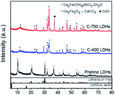 |
| | Fig. 1 XRD patterns of CaFe-LDHs with different structural transformations for pristine LDHs, C-400 LDHs, and C-700 LDHs. | |
The FT-IR spectra of CaFe-LDHs were analyzed to identify the structural transformation by comparing chemical bonding of functional groups (ESI 1†). The characteristic peak at 1640 cm−1 corresponds to the H–O–H bending vibration of the interlayer water in the crystalline structure, and the characteristic sharp absorption band at around 1350 cm−1 is the asymmetric stretching mode of NO3− in the interlayer (ESI 1(b)†). The intense broad bands observed at 3585 cm−1 are associated with stretching vibrations of structural OH− groups in Ca(OH)2 and Fe(OH)2 (ESI 1(c)†). The peaks at 749 and 580 cm−1 are attributed to stretching vibrations of Ca–O or Fe–O (metal–O) in lattices as shown in ESI 1(d).†43,44 Because the crystallized water molecules were removed, the band at 1640 cm−1 became weaker after calcination and completely decomposed in the case of C-400 LDHs. The gradual decrease of NO3− stretching vibration intensity at 1350 cm−1 also implies decomposition of the NO3− anion, which was completely decomposed in C-700 LDHs. The noticeable decrease in OH− groups in C-400 LDHs implies that the OH− groups of cationic layers, such as Ca(OH)2 and Fe(OH)2, decomposed during thermal treatment at 400 °C. Subsequently, the peak intensity increase of Ca–Fe–O at 749 and 580 cm−1 indicates that the pristine LDHs transformed into oxidized metal oxide structures. The commercial CaCO3 peaks were observed at 1394 cm−1 (υ3 asymmetric CO32−) along with a sharp band at 871 cm−1 (υ2 asymmetric CO32−).45 Those bands decreased in peak intensity with increasing calcination temperature from 400 °C to 700 °C, and a structural transformation occurred at the C-400 LDHs based on XRD data.
Fig. 2 shows the Scanning electron microscopy (SEM) images of Pristine LDHs, C-400 LDHs and C-700 LDHs. As shown, the morphology of C-400 LDHs changed from a smooth surface into one with more roughness and pores because the water of crystallization and the interlayer anions were removed by transformation from pristine LDHs to a metal oxide phase. This morphology change distinctly appears and consists primarily of individual spherical particles in C-700 LDHs, which is related to transformation of CaCO3 to CaO. In addition, the lateral particle size of CaFe-LDHs confirmed about 1 μm of pristine LDHs, about 500 nm of C-400 LDHs and about 300 nm of C-700 LDHs. The particle size is an important factor regarding anion exchange.46
 |
| | Fig. 2 SEM images of (a) pristine LDHs, (b) C-400 LDHs, and (c) C-700 LDHs. | |
Fig. 3 displays the transmission electron microscopy (TEM) images and associated Selected area diffraction (SAED) patterns of CaFe-LDHs. Pristine LDHs revealed the typical crystallographic layered structure of CaFe-LDHs, which had SAED patterns revealing the (300) and (103) planes with lattice constants of 1.70 Å and 2.50 Å. However, C-400 LDHs indicated the existence of the (006), (110), and (116) planes corresponding to a CaCO3 rhombohedral structure after thermal treatment at 400 °C. The unique thermal treatment-induced by-product, CaO, was confirmed in C-700 LDHs, and it was identified in XRD as shown in Fig. 1. Thus, the SEAD patterns validate the gradual structural and crystallographic transitions as a function of temperature from 400 to 700 °C.
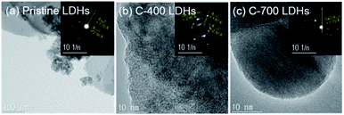 |
| | Fig. 3 TEM images and SAED patterns of (a) pristine LDHs, (b) C-400 LDHs, and (c) C-700 LDHs. | |
3.2. Performance and mechanism of Cl−, SO42−, and CO32− anion adsorption by CaFe-LDHs
An experiment was conducted to test the simultaneous removal of deleterious anions found in aggressive natural environments. Fig. 4 shows the removal of Cl−, SO42−, and CO32− anions by applying different types of CaFe-LDHs (pristine LDHs, C-400 LDHs and C-700 LDHs) for 60 min. The percentage removal efficiency was estimated according to eqn (5).| |
 | (5) |
where C0 and Ce are the initial and equilibrium anion concentration (mg L−1), respectively.
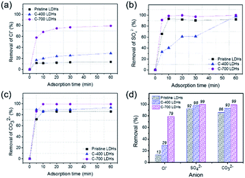 |
| | Fig. 4 Ion chromatograph of removal performance of CaFe-LDHs: pristine LDHs, C-400 LDHs, and C-700 LDHs, toward different adsorption anions: (a) Cl−, (b) SO42−, and (c) CO32− as a function of reaction interaction time toward anions, and (d) anion removal percentage toward anionic species at a fixed adsorption time (at 60 min). | |
As shown in Fig. 4(a), the removal (%) of Cl− anions by pristine LDHs, C-400 LDHs, and C-700 LDHs was 13%, 16.98%, and 57.90%, respectively, for 5 min-adsorption time at the initial stage of reaction. The removal of Cl− anions gradually increased at 60 min and reached 13.41% for pristine LDHs, 29.25% for C-400 LDHs, and 79.62% for C-700 LDHs. The removal efficiency by C-700 LDHs was 5.94 times the corresponding value of pristine LDHs, indicating outstanding removal ability of Cl− anions. The effect of SO42− anion removal by employing the CaFe-LDHs is shown in Fig. 4(b). The results show that removal of SO42− anions rapidly increased from 0% to 65.80% for pristine LDHs, 32.96% for C-400 LDHs, and 91% for C-700 LDHs for just 5 min of initial adsorption. The values then reached 92.25% (pristine LDHs), 98.07% (C-400 LDHs), and 99.86% (C-700 LDHs) when adsorption was complete after 60 min. As shown in Fig. 4(c), the removal of CO32− anions was faster than other anion species for all the tested LDHs. C-700 LDH exhibited almost 100% of carbonate removal after 10 minutes of anion adsorption. Consequently, C-700 LDHs showed the highest removal efficiency toward Cl−, SO42−, and CO32− anions, with values of 79.62%, 99.86%, and 99.30%, respectively (Fig. 4(d)).
The FT-IR spectra of CaFe-LDHs including (a) pristine LDHs, (b) C-400 LDHs, (c) C-700 LDHs and their post-adsorption samples after uptake-tests of Cl−, SO42−, and CO32− anions are shown in ESI 2.† In the spectrum of the pristine LDHs (ESI. 2(a)†), adsorption peaks at 1360, 1116, and 1480 cm−1 can be attributed to Cl−, SO42−, and CO32− interlayer anion stretching, respectively.43,47,48 Typical CaFe-LDHs peaks were observed at 580 and 749 cm−1 in the spectrum of all samples as well as metal–O at 1640 cm−1 for H–O–H and 3585 cm−1 for hydroxyl groups in Ca(OH)2 and Fe(OH)2 after anion adsorption. C-400 LDHs and C-700 LDHs (ESI. 2(b) and (c)†) not subjected to the anion adsorption test showed typical H–O–H peaks of bending vibration (1360 cm−1) and stretching vibration (3585 cm−1) induced by hydroxyl groups, which were removed during heating. However, the adsorption peaks returned after adsorption of Cl−, SO42−, and CO32− anions because the hydroxyl groups and water from crystallization were recovered by a refolding process that occurs in an aqueous atmosphere. Thus, there is good evidence of successful adsorption of the three anions (Cl−, SO42−, and CO32−) and reconstruction processes of CaFe-LDHs.
Reconstructed CaFe-LDHs were characterized by XRD after 60 min-adsorption tests with anions Cl−, SO42−, and CO32− anions as shown in ESI 3.† The characteristic diffractions of typical CaFe-LDHs were recognized as rhombohedral structures in all LDHs samples, including plane (006) and (0012) after adsorption of Cl−, SO42−, and CO32− anions. The crystalline LDHs structures corresponded to Ca2Fe(OH)6(Cl)·2H2O (JCPDS no. 44-445) after Cl− adsorption, Ca2Fe(OH6)(SO4)0.5·3H2O (JCPDS no. 44-448) after SO42− adsorption, and Ca2Fe(OH6)(CO3)0.5·3H2O (JCPDS no. 43-480) after CO32− adsorption. Simultaneously, the crystallinity of the CaFe-LDHs decreased with anion adsorption due to the reconstruction phenomenon, which is the so called memory effect.49,50 As shown in ESI 3(a),† the basal spacing decreased, and the 2θ on the (006) plane increased from 10.36° (NO3−) to 11.32° (Cl−) because the anion ionic radius of Cl− (1.75 Å) was smaller than that of the NO3− (1.79 Å). The Cl− anion was partially substituted with NO3− present in the interlayer, which led to two types of interstratified pristine LDHs. Also, the 2θ on the (006) plane of CO32− interlayered LDH (11.64°) was higher than that of pristine LDHs.51 In a continuation of the pre-adsorption measurements shown in Fig. 1, post-adsorption C-400 LDHs also included secondary crystalline phases of CaCO3 (2θ = 29.36°) in all CaFe-LDHs samples even after particle reconstruction (ESI 3(b)†). This is because CaCO3 is a basic salt with very low solubility in water. Interestingly, a characteristic peak of Fe2O3 was observed after anion adsorption with C-400 LDHs and C-700 LDHs. Moreover, the CaFe-based metal oxide, Ca2Fe2O5, converted into CaFe-LDHs during the refolding process in an aqueous solution by intercalating anion species (Cl−, SO42−, and CO32−). Therefore, C-400 LDHs refolded in aqueous solutions by exchanging anions via reconstruction of Ca2Fe2O5 according to the following reactions [eqn (6)–(8)]:
| | |
Ca2Fe2O5 + 2CaCO3 + Cl− + 5.5H2O → Ca2Fe(OH)6(Cl)·2H2O + 0.5Fe2O3 + 2CaCO3 + OH−
| (6) |
| | |
Ca2Fe2O5 + 2CaCO3 + 0.5SO42− + 5.5H2O → Ca2Fe(OH)6(SO4)0.5·2H2O + 0.5Fe2O3 + 2CaCO3 + OH−
| (7) |
| | |
Ca2Fe2O5 + 2CaCO3 + 0.5CO32− + 5.5H2O → Ca2Fe(OH)6(CO3)0.5·2H2O + 0.5Fe2O3 + 2CaCO3 + OH−
| (8) |
In particular, the CaFe-LDHs prepared after thermal treatment at C-700 LDHs showed a pure crystalline structure of CaFe-LDHs with phase transformation of CaO into both a Ca(OH)2 phase and CaCl2, CaSO4, and CaCO3 phases depending on the anion species. Thus, the C-700 LDHs may undergo reconstruction via the following chemical reaction in water with specific anions [eqn (9)–(11)]:
| | |
Ca2Fe2O5 + 2CaO + 4Cl− + 7.5H2O → Ca2Fe(OH)6(Cl)·2H2O + 0.5Fe2O3 + 0.5Ca(OH)2 + 1.5CaCl2 + 4OH−
| (9) |
| | |
Ca2Fe2O5 + 2CaO + 1.5SO42− + 7.5H2O → Ca2Fe(OH)6(SO4)0.5·2H2O + 0.5Fe2O3 + Ca(OH)2 + CaSO4 + 3OH−
| (10) |
| | |
Ca2Fe2O5 + 2CaO + 1.5CO32− + 7.5H2O → Ca2Fe(OH)6(CO3)0.5·2H2O + 0.5Fe2O3 + Ca(OH)2 + CaCO3 + 3OH−
| (11) |
C-400 and C-700 LDHs showed low crystallinity with individual interlayer anions of Cl−, SO42−, and CO32− compared to pristine LDH. This may be related to the phase transfer of Ca2Fe2O5 to a layer-by layer structure of CaFe-LDHs by reconstruction.
3.3. Competitive adsorption performance of CaFe-LDHs by structural transformation caused by Cl−, SO42−, and CO32− anions
To evaluate the removal performance of CaFe-LDHs in a mixture of three anions (Cl−, SO42−, and CO32−), competitive adsorption was studied by adding the pristine, C-400, and C-700 LDHs to an aqueous anionic solution. As shown in Fig. 5, 100% removal of SO42− and CO32− anions in all CaFe-LDHs was observed after 5 minutes of adsorption time. The removal performance toward Cl− anions, however, was low after 5 min of adsorption and only reached 14.34% for pristine LDHs, 27.09% for C-400 LDHs, and 92.43% for C-700 LDHs at 180 min of adsorption time. This implies that the removal capacity of the prepared CaFe-LDHs is fastest toward SO42− and CO32− anions under fixed anion concentrations. The required adsorption time until adsorption saturation decreased in the order of CO32− and SO42− > Cl− over 180 min of adsorption.
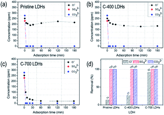 |
| | Fig. 5 Competitive adsorption toward the mixture of ionic species: Cl−, SO42− and CO32− anions (a) pristine LDHs, (b) C-400 LDHs, and (c) C-700 LDHs and (d) removal percentage toward anionic species fixed adsorption 180 min. | |
3.4. Adsorption kinetics of Cl−, SO42−, and CO32
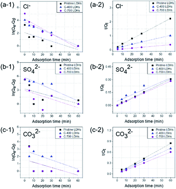
To investigate the differences in anion absorption performance for CaFe-LDHs, the adsorption kinetics of Cl−, SO42−, and CO32− anions on CaFe-LDHs were determined by fitting the experimental data to the linearized form of pseudo-first-order (eqn (12)) and pseudo-second-order (eqn (13)) models:| |
ln(Qe − Qt) = ln![[thin space (1/6-em)]](https://www.rsc.org/images/entities/char_2009.gif) Qe − k1t Qe − k1t
| (12) |
| |
 | (13) |
Here, Qe and Qt are the amounts of anions adsorbed (mg g−1) per unit of LDHs at equilibrium and at specified time t (min), respectively. k1 and k2 are the pseudo-first-order and pseudo second-order rate constants, respectively. Correlation coefficients (R2) were compared in determining the kinetic model for quantitative evaluation. The pseudo-first- and pseudo-second- order plots for sorption of anions by CaFe-LDHs as a function of adsorption time are fitted in Fig. 6, and the specific model parameters obtained toward Cl−, SO42−, and CO32− anion concentrations are arranged in Table 1.
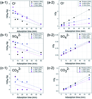 |
| | Fig. 6 (a–c) Pseudo-first-order and (a-2, b-2 and c-2) pseudo-second-order kinetic plots for sorption of CaFe-LDHs with different adsorption anions: (a-1 and a-2) Cl−, (b-1 and b-2) SO42− and (c-1 and c-2) CO32−. | |
Table 1 Coefficients of pseudo-first-order and pseudo-second-order parameters for Cl−, SO42−, and CO32− adsorption by CaFe-LDHs, pristine, C-400, and C-700 LDHs
| Anion |
LDHs |
Pseudo first order kinetic parameters |
Pseudo second order kinetic parameters |
| K1 (min−1) |
Qe (mg) |
R2 |
K2 (mg−1 min−1) |
Qe (mg) |
R2 |
| Cl− |
Pristine LDHs |
0.091 |
3.805 |
0.913 |
0.038 |
14.343 |
0.954 |
| C-400 LDHs |
0.060 |
19.950 |
0.892 |
0.001 |
31.849 |
0.974 |
| C-700 LDHs |
0.106 |
32.621 |
0.810 |
0.001 |
85.294 |
0.957 |
| SO42− |
Pristine LDHs |
0.053 |
25.460 |
0.140 |
0.008 |
197.516 |
0.998 |
| C-400 LDHs |
0.085 |
307.570 |
0.860 |
0.001 |
222.150 |
0.941 |
| C-700 LDHs |
0.063 |
19.017 |
0.192 |
0.018 |
211.691 |
0.999 |
| CO32− |
Pristine LDHs |
0.036 |
2.789 |
0.017 |
0.012 |
73.243 |
0.994 |
| C-400 LDHs |
0.042 |
16.367 |
0.762 |
0.006 |
86.885 |
0.996 |
| C-700 LDHs |
0.035 |
4.687 |
0.017 |
0.010 |
100.640 |
0.998 |
The data were very well fitted when using a pseudo-second-order plot, as shown in Table 1. The high correlation coefficient values (R2) obtained for all the LDHs adsorbent samples confirmed that the pseudo-second-order model describing the Cl−, SO42−, and CO32− anions kinetics was very well fit compared to the pseudo-first-order. Based on the kinetic parameters, the pseudo-second order model data suggest that the rate limiting step during Cl−, SO42−, and CO32− anion adsorption onto CaFe-LDHs was primarily chemisorption. Therefore, chemisorption, which typically involves electrostatic attraction and chemical bonding between adsorbate and adsorbent, was the dominant factor for adsorbate anions Cl−, SO42−, and CO32− onto CaFe-LDHs.52
3.5. Equilibrium sorption measurements and modelling
The aim of the adsorption isotherms is to correlate the adsorbate concentration in the solution and the adsorbed extent of metal ions at the adsorbate-to-adsorbent interface. Langmuir and Freundlich isotherm models were important for design of sorption systems (Fig. 7). The adsorption of Cl−, SO42−, and CO32− anions onto CaFe-LDHs (here, C-700 LDHs) was investigated, and the applicability of the isotherms described above was examined. The Langmuir model assumes that interactions occur on a homogenous surface by monolayer adsorption between ions. The Langmuir isotherm represents the equilibrium distribution of sorbate between solid and liquid phases and is often expressed as (eqn (14)):| |
 | (14) |
Here, Ce (mg L−1) is the concentration of sorbate at equilibrium, Qe (mg g−1) is the amount sorbed per mass of sorbent at equilibrium, KL (L mg−1) is the equilibrium constant related to the sorption energy between sorbate and sorbent, and Qmax (mg) is the limiting amount of sorbate that can be taken up per mass of sorbent. The Langmuir parameters were Qmax = 881.83 mg g−1 for Cl−, Qmax = 706.21 mg g−1 for SO42−, and Qmax = 879.73 mg g−1 for CO32−.
 |
| | Fig. 7 (a–c) Langmuir and (a-2, b-2 and c-2) Freundlich plots for sorption of CaFe-LDHs with different adsorption anions: (a-1 and a-2) Cl−, (b-1 and b-2) SO42−, and (c-1 and c-2) CO32−. | |
The Freundlich equation can be used to estimate the sorption intensity of sorbent toward sorbate as [eqn (15)]:
Here,
Qe (mg g
−1) is the amount of sorbed anion,
Ce is the equilibrium concentration, and
KF and
n are constants incorporating all parameters affecting the sorption process, such as sorption capacity and intensity. The isotherm constants in
eqn (14) and
(15), as well as the correlation coefficients (
R2) are given in
Table 2. Based on the
R2 values for LDHs samples and the maximum capacities, the equilibrium data were better fit using the Langmuir isotherm (with a high correlation coefficient) rather than the Freundlich isotherm. The high coefficient values for the Langmuir isotherm indicate monolayer sorption of Cl
−, SO
42−, and CO
32− anions onto CaFe-LDHs.
Table 2 Langmuir and Freundlich isotherm parameters for Cl−, SO42−, and CO32 adsorption by C-700 LDHs
| Anion |
Langmuir isotherm parameter |
Freundlich isotherm parameters |
| KL (L mg−1) |
Qmax (mg) |
R2 |
KF (L mg−1) |
n |
R2 |
| Cl− |
0.0006 |
881.8342 |
0.9988 |
3.1183 |
1.3050 |
0.9881 |
| SO42− |
0.0019 |
706.2140 |
0.6964 |
43.8870 |
3.9432 |
0.3627 |
| CO32− |
0.0006 |
879.7300 |
0.9999 |
0.8587 |
0.9841 |
0.9998 |
3.6. Corrosion protection of steel rebars with and without CaFe-LDHs
To study the effect of CaFe-LDHs on the corrosion protection behavior of a steel rebar, potentiodynamic polarization (PDP) curves for samples with and without CaFe-LDHs formed by structural transformation in NaCl, Na2SO4, and Na2CO3 solution are shown in Fig. 8.
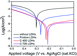 |
| | Fig. 8 Potentiodynamic polarization (PDP) curves obtained in NaCl, Na2SO4, and Na2CO3 solutions (250 ppm solution) without CaFe-LDHs and with CaFe-LDHs. | |
The values of electrochemical kinetic parameters such as corrosion potential (Ecorr), corrosion current (Icorr), anodic and cathodic Tafel slopes (βa and βc), and corrosion rate (CR) obtained from the curves by the extrapolation method are listed in Table 3.
Table 3 Electrochemical polarization parameters and calculated corrosion rate (mm per year) without LDHs and with LDHs in NaCl, Na2SO4, and Na2CO3 (ionic species: 250 ppm)
| Sample |
Ecorr (mV) |
Icorr (μA) |
βa (mV dec−1) |
βc (mV dec−1) |
CR (mm per year) |
| Without LDHs |
−298.57 |
161.73 |
1909.27 |
386.42 |
1876.56 × 10−3 |
| Pristine LDHs |
−256.31 |
5.23 |
142.62 |
126.74 |
60.68 × 10⁻³ |
| C-400 LDHs |
−220.31 |
0.38 |
81.53 |
55.61 |
4.41 × 10⁻³ |
| C-700 LDHs |
−218.82 |
0.23 |
68.91 |
36.48 |
2.67 × 10⁻³ |
The corrosion rates (mm per year) from polarization were calculated utilizing the equation below [eqn (16)]:
| |
 | (16) |
Here, EW is the equivalent weight of Fe (27 g),
K is the corrosion rate constant (3272 mm per year per A per cm),
ρ is the density of Fe (g cm
−3), and
A is the surface area of the electrode. The
Icorr value of the case with CaFe-LDHs was noticeably lower that of the case without CaFe-LDHs. This means that the electrochemical reaction between the electrolyte and sample was reduced, decreasing the participation of electrons in the reaction. The CR value without CaFe-LDHs was 1876.56 × 10
−3 mm per year for the steel rebar. This value remarkably decreased only because of the presence of CaFe-LDHs. Compared to the steel rebar without CaFe-LDHs, the CR values gradually decreased to 60.68 × 10
−3 mm per year for pristine LDHs, and the structural modulations further enhanced the anti-corrosion effect to 2.67 × 10
−3 mm per year for C-400 LDHs and to 2.67 × 10
−3 mm per year for C-700 LDHs. In other words, the CR of C-700 LDHs (2.67 × 10
−3 mm per year) implies that, when the steel rebar is exposed to a mixture of anionic species, the speed of steel corrosion is accelerated to 702.6 times faster than when it is protected by the C-700 LDHs (which present the best anion adsorption properties). As can be seen from the Nyquist plot of rebar without and with CaFe-LDHs in
Fig. 9(a). The diameter of the semicircle significantly increased for protective CaFe-LDHs. It is means that the resistance is increased and corrosion is reduced. The corrosion protection with CaFe-LDHs led to an obvious increase in the diameter of the capacitive loop,
53 as confirmed by Bode plots given in
Fig. 9(c). The equivalent-circuit model constants in
Fig. 9(d) were applied as these account for corrosion protection. In this equivalent circuit model, the steel rebar is considered to have a porous structure and to show capacitive behavior.
54–57 To compare the inhibition efficiencies (IE) with and without CaFe-LDHs, impedance parameters are shown in
Table 4.
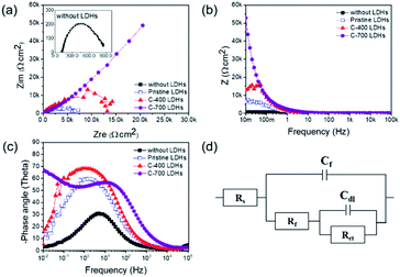 |
| | Fig. 9 (a) Nyquist plots, (b) Bode plots, and (c) phase angle plots, performed at the corrosion potentials for NaCl, Na2SO4, and Na2CO3 (250 ppm solutions) without CaFe-LDHs and with CaFe-LDHs. (d) Equivalent electrical circuit (EEC) used to fit the electrochemical impedance data. | |
Table 4 Impedance parameters and calculated inhibition efficiencies (IE%) without LDHs and with LDHs in NaCl, Na2SO4, and Na2CO3 solutions (ionic species: 250 ppm)
| Sample |
Rs (Ω cm2) |
Cf (μF cm−2) |
Rf (Ω cm2) |
Cdl (μF cm−2) |
Rct (Ω cm2) |
IE (%) |
| Without LDHs |
123.32 |
81.00 |
0.28 × 10³ |
524.80 |
0.38 × 10³ |
— |
| Pristine LDHs |
71.02 |
73.70 |
0.67 × 10³ |
157.63 |
5.41 × 10³ |
93.03 |
| C-400 LDHs |
65.22 |
59.33 |
1.13 × 10³ |
104.32 |
14.86 × 10³ |
97.47 |
| C-700 LDHs |
57.20 |
58.51 |
217.97 × 10³ |
217.95 |
218.97 × 10³ |
99.83 |
Rs refers to electrolyte resistance, Rf and Cf are electrolyte resistance inside pores and film capacitance, respectively. Rct is the charge transfer resistance of electrochemical processes taking place inside the pores, and Cdl is the double-layer capacitance. Here, the Cdl value observed without LDHs was 524.80 (μF cm−2), and this value generally decreased with use of CaFe-LDHs. Specifically, it decreased to 157.63 (μF cm−2) for pristine LDHs, to 104.32 (μF cm−2) for C-400 LDHs, and to 217.95 (μF cm−2) for C-700 LDHs. This trend can be explained according to the Helmholtz model, where Cdl is expressed as [eqn (17)]:
| |
 | (17) |
Here,
S is the exposed surface area of the steel specimen,
d represents the thickness of the double layer,
εr denotes the dielectric constant of the electrolyte inside the capacitor, and
ε0 is the vacuum dielectric constant. The steel rebar without CaFe-LDHs was expected to have a higher exposed surface area induced by destructive corrosion, leading to the increase in
Cdl values compared to that with CaFe-LDHs. Because addition of CaFe-LDHs decreased the concentration of aggressive Cl
−, SO
42−, and CO
32− anions, corrosion of the steel specimen was significantly reduced by decreasing the exposed surface area. In addition, it is well known that the IE of a steel rebar is inversely proportional to the
Rct value. In a solution without CaFe-LDHs, the
Rct value was 0.38 × 10
3 Ω cm
2. This value was increased to 5.41 × 10
3 Ω cm
2 by pristine LDHs, to 14.86 × 10
3 Ω cm
2 by C-400 LDHs, and to 218.97 × 10
3 Ω cm
2 by C-700 LDHs. To clearly illustrate the inhibition effect of CaFe-LDHs, the IE% of the CaFe-LDHs was calculated using the following equation [
eqn (18)]:
| |
 | (18) |
Here,
Rct, with CaFe-LDHs and
Rct, without CaFe-LDHs are the charge transfer resistances for the steel specimens in the presence and absence of the CaFe-LDHs, respectively. According to
Table 4, the solution containing the steel specimen and CaFe-LDHs showed inhibition effects. Specifically, the highest IE% (99.83%) was obtained when C-700 LDHs was applied.
3.7. Synergy of simultaneous adsorption of anions and corrosion prevention in steel rebar by CaFe-LDHs with structural modulation
Rapid removal of harmful anions not long after their introduction into the aqueous solution or into the matrix of steel-reinforced concrete is crucial for coating materials or anti-corrosion additives. This property can be related to (1) adsorption rate of anions (i.e., removal percentage of anions (%) per given reaction time [see Section 4.2]) and (2) removal capacity (i.e., maximum amount of ionic species removed (mg) per unit mass of LDHs (g) [see Section 4.5]). The anion removal performance is more distinct when we compare the removal capacity of C-700 LDHs with previously released reports (Table 5).
Table 5 Comparison of LDHs removal capacity for anionic species obtained in previous reports by equilibrium sorption measurements
| LDHs |
Removal capacity of Cl− (mg g−1) |
Reference |
| C-700 LDHs |
881.83 |
Our study |
| MgAl-LDHs |
257.00 |
50 |
| MgAl-LDHs |
168.00 |
51 |
| MgAl-LDHs |
149.50 |
52 |
| MgAl-LDHs |
128.20 |
12 |
| LDHs |
Removal capacity of SO42− (mg g−1) |
Reference |
| C-700 LDHs |
706.21 |
Our study |
| MgAl-LDHs |
144.09 |
17 |
| Zn–Al LDHs |
98.13 |
53 |
| Mg–Fe LDHs |
68.73 |
54 |
| LDHs |
Removal capacity of CO32− (mg g−1) |
Reference |
| C-700 LDHs |
879.73 |
Our study |
The Qmax for Cl− was 881.83 mg g−1, which is over 3.4 times that of previous studies. Furthermore, the value for SO42− (706.21 mg g−1) was over 5.69 times higher than previous reports.11,16,58–62 The value for CO32− was 879.73 mg g−1, which was not previously reported. In addition, no comparable result has been observed in terms of removal capacity of CO32.
This synergy was induced by (1) anion capture by reconstruction (2) capture by chemical reaction with metal oxide (see Fig. 10). 1 mole of pristine LDHs with crystallinity of Ca2Fe(OH)6(NO3)·2H2O can exchange 1 mole of monovalent anion including Cl− with NO3−, while C-700 LDHs can capture 4 moles of Cl−, 1.5 moles of SO42−, and 1.5 moles of CO32− [also see eqn (6)–(11)]. Here, 1 mole of Cl− ions was captured by intercalation between cationic layers during the refolding process, and another 3 moles of Cl− ions were captured by chemical reaction with CaO, which was generated during thermal treatment at 700 °C. This metal oxide moiety, initiated by pristine-LDHs, also captures Cl−, SO42− or CO32− ions by chemical reaction other than capturing by the refolding process, which cannot be realized even after calcination of typical Mg–Al-LDHs or Ca–Al-LDHs.63 This enhanced adsorption of ionic species in aqueous solution reduced corrosion in the steel specimen in water because of prompt removal of corrosion sources Cl− and SO42−, as well as another deleterious anion, CO32−, upon introduction to reaction media or building matrix.
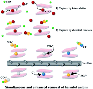 |
| | Fig. 10 Adsorption and corrosion protection mechanism of C-700 LDHs with different anions; Cl−, SO42− and CO32−. | |
Hence, the enhanced removal performance of Cl−, SO42−, and CO32− and anti-corrosion effects by CaFe-LDH-induced crystalline structures utilized in this work suggest that CaFe-LDHs are promising materials for superior corrosion protection in concrete structures.
4. Conclusions
In this study, we fabricated CaFe-LDHs by structural transformation, demonstrated their simultaneous removal of destructive anions (Cl−, SO42−, and CO32−) in aqueous solutions and superior anti-corrosion efficiency. In the investigation of adsorption kinetics, pseudo-second-order kinetics and Langmuir isotherm models well fit the data, which confirms that the target anions were effectively removed with the CaFe-LDHs predominantly by chemisorption through monolayer sorption. Compared with previous reports, the removal capacity (Qmax) of C-700 LDHs was remarkably enhanced. The Qmax of Cl− (881.83 mg g−1) was over 3.4 times that of previous work, while that of SO42− (706.21 mg g−1) was over 5.69 times that of previous literature. This corrosion inhibition efficiency by C-700 LDHs reached 98.83% compared to that of bare rebar without LDHs. This synergy was induced by (1) anion capture by reconstruction (2) capture by chemical reaction with metal oxide of C-700 LDHs.
Our data show that the durability and sustainability of buildings can be enhanced by employing the CaFe-LDHs as a coating material, filler in concrete, or additive in the construction industry.
Conflicts of interest
There are no conflicts to declare.
Acknowledgements
This work was supported by the Clean Production Technology Program of the Korea Evaluation Institute of Industrial Technology (KIET), which was granted financial resources from the Ministry of Trade, Industry and Energy, Korea (No. 20000458) and by a National Research Foundation of Korea (NRF) grant funded by the Korean government (MSIT) (No. 2015R1A5A1037548). This research was supported by the Nano & Material Technology Development Program through the National Research Foundation of Korea (NRF) funded by the Ministry of Science, ICT and Future Planning (No. 2016M3A7B4900044).
Notes and references
- H. Shirkhani, J. Y. Zhang and Z. Lounis, Nat. Hazards Rev., 2020, 21, 1–14 CrossRef.
- M. R. Geiker, A. Michel, H. Stang and M. D. Lepech, Cem. Concr. Res., 2019, 122, 189–195 CrossRef CAS.
- R. E. Melchers, J. Mar. Sci. Eng., 2020, 8, 1–12 Search PubMed.
- F. Winnefeld, M. Ben Haha, G. Le Saout, M. Costoya, S.-C. Ko and B. Lothenbach, J. Sustainable Cem.-Based Mater., 2014, 4, 85–100 CrossRef.
- S. D. Wang, K. L. Scrivener and P. L. Pratt, Cem. Concr. Res., 1994, 1033–1043 CrossRef CAS.
- S. Song, D. Sohn, H. Jennings and T. Mason, J. Mater. Sci., 2000, 35, 249–257 CrossRef CAS.
- M. Moreno, W. Morris, M. G. Alvarez and G. S. Duffó, Corros. Sci., 2004, 46, 2681–2699 CrossRef CAS.
- Z. Dong and A. Poursaee, Constr. Build. Mater., 2020, 240, 117955 CrossRef CAS.
- H. S. Wang, X. Cao, H. K. Gu, Y. Y. Liu, Y. B. Li, Z. W. Zhang, W. Huang, H. X. Wang, J. Y. Wang, W. Xu, J. G. Zhang and Y. Cui, ACS Nano, 2020, 14, 4601–4608 CrossRef CAS PubMed.
- K. Wang, H. X. Chen, X. F. Zhang, Y. X. Tong, S. Q. Song, P. Tsiakaras and Y. Wang, Appl. Catal., B, 2020, 264, 118468 CrossRef.
- J. Zuo, B. Wu, C. Luo, B. Dong and F. Xing, Corros. Sci., 2019, 152, 120–129 CrossRef CAS.
- A. M. Neville, Properties of concrete, Pearson, Edinburgh, England, 5th edn, 2011 Search PubMed.
- Z. Yang, H. Fischer and R. Polder, Mater. Corros., 2013, 64, 1066–1074 CrossRef CAS.
- B.-G. Paik, G.-D. Kim, K.-Y. Kim, H.-S. Seol, B.-S. Hyun, S.-G. Lee and Y.-R. Jung, Ocean Eng., 2013, 73, 139–148 CrossRef.
- Y. Ben Amor, L. Bousselmi, H. Takenouti and E. Triki, Corros. Eng., Sci. Technol., 2005, 40, 129–135 CrossRef CAS.
- J. Xu, Q. Tan and Y. Mei, Corros. Sci., 2020, 163, 108223 CrossRef CAS.
- Y.-z. Zhang, Y.-f. Fan and H.-n. Li, Int. J. Corros., 2012, 2012, 1–7 Search PubMed.
- N. Kabashi, C. Krasniqi, A. Sadikaj, S. Bublaku, M. Ali and H. Morina, Corrosion In Concrete Under Sulphate And Chloride Attacks, 2017 Search PubMed.
- C. Qian, R. Li, M. Luo and H. Chen, J. Wuhan Univ. Technol., Mater. Sci. Ed., 2016, 31, 557–562 CrossRef CAS.
- A. Królikowski and J. Kuziak, Electrochim. Acta, 2011, 56, 7845–7853 CrossRef.
- T. T. X. Hang, T. A. Truc, N. T. Duong, N. Pébère and M.-G. Olivier, Prog. Org. Coat., 2012, 74, 343–348 CrossRef CAS.
- M. Xu and M. Wei, Adv. Funct. Mater., 2018, 28, 1802943 CrossRef.
- X. Mei, R. Liang, L. Peng, T. Hu and M. Wei, J. Mater. Chem. B, 2017, 5, 3212–3216 RSC.
- L. P. Cardoso, R. Celis, J. Cornejo and J. B. Valim, J. Agric. Food Chem., 2006, 54, 5968–5975 CrossRef CAS PubMed.
- Z. M. Mir, A. Bastos, D. Hoche and M. L. Zheludkevich, Adv. Eng. Mater., 2020, 2000398 CrossRef CAS.
- G. Mishra, B. Dash and S. Pandey, Appl. Clay Sci., 2018, 153, 172–186 CrossRef CAS.
- K. L. Erickson, T. E. Bostrom and R. L. Frost, Mater. Lett., 2005, 59, 226–229 CrossRef CAS.
- Z. Gao, K. Sasaki and X. Qiu, Langmuir, 2018, 34, 5386–5395 CrossRef CAS PubMed.
- S. Mondal, S. Dasgupta and K. Maji, Mater. Sci. Eng., 2016, 68, 557–564 CrossRef CAS PubMed.
- Q. Wang, Y. Gao, J. Luo, Z. Zhong, A. Borgna, Z. Guo and D. O'Hare, RSC Adv., 2013, 3, 3414–3420 RSC.
- J. L. Chen, L. Fang, F. Wu, X. G. Zeng, J. Hu, S. F. Zhang, B. Jiang and H. J. Luo, Trans. Nonferrous Met. Soc. China, 2020, 30, 2424–2434 CrossRef CAS.
- F. Zhang, C. L. Zhang, L. Song, R. C. Zeng, Z. G. Liu and H. Z. Cui, Trans. Nonferrous Met. Soc. China, 2015, 25, 3498–3504 CrossRef CAS.
- J. L. Chen, L. Fang, F. Wu, J. Xie, J. Hu, B. Jiang and H. J. Luo, Prog. Org. Coat., 2019, 136, 105234 CrossRef CAS.
- M. A. Iqbal and M. Fedel, Surf. Coat. Technol., 2018, 352, 166–174 CrossRef CAS.
- S. K. Poznyak, J. Tedim, L. M. Rodrigues, A. N. Salak, M. L. Zheludkevich, L. F. Dick and M. G. Ferreira, ACS Appl. Mater. Interfaces, 2009, 1, 2353–2362 CrossRef CAS PubMed.
- L. Yang, M. Chen, Z. Lu, Y. Huang, J. Wang, L. Lu and X. Cheng, Cem. Concr. Compos., 2020, 114, 103817 CrossRef CAS.
- N. Jahanzeb, J.-H. Shin, J. Singh, Y.-U. Heo and S.-H. Choi, Mater. Sci. Eng. A, 2017, 700, 338–350 CrossRef CAS.
- M. Al-Jaberi, S. Naille, M. Dossot and C. Ruby, J. Mol. Struct., 2015, 1102, 253–260 CrossRef CAS.
- G. Varga, V. Kozma, V. J. Kolcsár, Á. Kukovecz, Z. Kónya, P. Sipos, I. Pálinkó and G. Szὅllὅsi, Mol. Catal., 2020, 482, 110675 CrossRef CAS.
- M. Szabados, Z. Kónya, Á. Kukovecz, P. Sipos and I. Pálinkó, Appl. Clay Sci., 2019, 174, 138–145 CrossRef CAS.
- M. Taei, E. Havakeshian, H. Salavati and F. Abedi, RSC Adv., 2016, 6, 27293–27300 RSC.
- Y. Xu, H. Hou, Q. Liu, J. Liu, L. Dou and G. Qian, Desalin. Water Treat., 2015, 57, 7918–7925 CrossRef.
- Y. Wu, Y. Yu, J. Z. Zhou, J. Liu, Y. Chi, Z. P. Xu and G. Qian, Chem. Eng. J., 2012, 179, 72–79 CrossRef CAS.
- F. Z. Mahjoubi, A. Khalidi, M. Abdennouri and N. Barka, Journal of Taibah University for Science, 2017, 11, 90–100 CrossRef.
- N. Butto, G. Cabrera-Barjas and A. Neira-Carrillo, Crystals, 2018, 8, 82 CrossRef.
- C. Gomes, Z. Mir, A. C. Bastos, F. Maia, C. Rocha, J. Tedim, M. L. Zheludkevich and M. Ferreira, Effect of Layered Double Hydroxides on the Performance and Service Life of Reinforced Concrete, 2019 Search PubMed.
- H.-m. Zhang, S.-h. Zhang, P. Stewart, C.-h. Zhu, W.-j. Liu, A. Hexemer, E. Schaible and C. Wang, Chin. J. Polym. Sci., 2016, 34, 542–551 CrossRef CAS.
- T. Ishizaki, S. Chiba, K. Watanabe and H. Suzuki, J. Mater. Chem. A, 2013, 1, 8968–8977 RSC.
- G. Mishra, B. Dash and S. Pandey, Appl. Clay Sci., 2018, 153, 172–186 CrossRef CAS.
- L. Moyo, N. Nhlapo and W. W. Focke, J. Mater. Sci., 2008, 43, 6144–6158 CrossRef CAS.
- S. Marappa, R. Shivaramaiah and P. Vishnu, Eur. J. Inorg. Chem., 2013, 2013, 2122–2128 CrossRef CAS.
- T. A. Saleh, A. M. Muhammad and S. A. Ali, J. Colloid Interface Sci., 2016, 468, 324–333 CrossRef CAS PubMed.
- W. Lee, R. Ji, U. Gösele and K. Nielsch, Nat. Mater., 2006, 5, 741–747 CrossRef CAS PubMed.
- J. Xu, Q. Tan and Y. Mei, Corros. Sci., 2020, 163, 108223 CrossRef CAS.
- I. Imanieh and A. Afshar, J. Mater. Res. Technol., 2019, 8, 3004–3023 CrossRef CAS.
- L. F. Hou, Y. L. Li, J. L. Sun, S. H. Zhang, H. Wei and Y. H. Wei, Appl. Surf. Sci., 2019, 487, 101–108 CrossRef CAS.
- A. Liu, X. Ju, H. Tian, H. Yang and W. Li, Appl. Surf. Sci., 2019, 493, 239–249 CrossRef CAS.
- S. Yoon, J. Moon, S. Bae, X. Duan, E. P. Giannelis and P. M. Monteiro, Mater. Chem. Phys., 2014, 145, 376–386 CrossRef CAS.
- L. Lv, J. He, M. Wei, D. G. Evans and X. Duan, Water Res., 2006, 40, 735–743 CrossRef CAS PubMed.
- Y. Zhao, W. Hu, J. Chen and L. Lv, Desalin. Water Treat., 2012, 36, 50–56 CrossRef.
- S. Iftekhar, M. E. Kucuk, V. Srivastava, E. Repo and M. Sillanpaa, Chemosphere, 2018, 209, 470–479 CrossRef CAS PubMed.
- J. Liu, X. Yue, Y. Yu and Y. Guo, Desalin. Water Treat., 2014, 56, 274–283 CrossRef.
- X. Ke, S. A. Bernal and J. L. Provis, Cem. Concr. Res., 2017, 100, 1–13 CrossRef CAS.
Footnote |
| † Electronic supplementary information (ESI) available. See DOI: 10.1039/d1ra00300c |
|
| This journal is © The Royal Society of Chemistry 2021 |
Click here to see how this site uses Cookies. View our privacy policy here.  Open Access Article
 a
a
![[thin space (1/6-em)]](https://www.rsc.org/images/entities/char_2009.gif) :
:![[thin space (1/6-em)]](https://www.rsc.org/images/entities/char_2009.gif) Fe3+ (2
Fe3+ (2![[thin space (1/6-em)]](https://www.rsc.org/images/entities/char_2009.gif) :
:![[thin space (1/6-em)]](https://www.rsc.org/images/entities/char_2009.gif) 1). During this process, the pH was maintained at 13, and the reaction was always performed at room temperature (25 °C). Then, the synthesized CaFe-LDHs were washed with excess quantities of ethanol to remove unwanted nitrate salt.
1). During this process, the pH was maintained at 13, and the reaction was always performed at room temperature (25 °C). Then, the synthesized CaFe-LDHs were washed with excess quantities of ethanol to remove unwanted nitrate salt.


![[thin space (1/6-em)]](https://www.rsc.org/images/entities/char_2009.gif) Qe − k1t
Qe − k1t


