 Open Access Article
Structure and electrochemical activity of nickel aluminium fluoride nanosheets during urea electro-oxidation in an alkaline solution †
Saba A. Aladeemyab,
Abdullah M. Al-Mayouf ab,
Mabrook S. Amera,
Nouf H. Alotaibia,
Mark T. Wellerc and
Mohamed A. Ghanem
 *a
*a
aElectrochemical Sciences Research Chair (ESRC), Chemistry Department, King Saud University, 11451 Riyadh, Saudi Arabia. E-mail: mghanem@ksu.edu.sa; Fax: +96614675992; Tel: +966 114670405
bK. A. CAR Energy Research and Innovation Center at Riyadh, Saudi Arabia
cChemistry Department, Cardiff University, Cardiff, CF10 3AT, UK
First published on 14th January 2021
Abstract
An electrocatalyst of potassium nickel aluminium hexafluoride (KNiAlF6) nanosheets has been prepared using solid-phase synthesis at 900 °C. X-ray diffraction, scanning electron microscopy, and conductivity studies confirmed the formation of KNiAlF6 nanosheets having a cubic defect pyrochlore structure with an average thickness of 60–70 nm and conductivity of 1.297 × 10³ S m−1. The electrochemical catalytic activity of the KNiAlF6 nanosheets was investigated for urea oxidation in alkaline solution. The results show that the KNiAlF6 nanosheets exhibit a mass activity of ∼395 mA cm−2 mg−1 at 1.65 V vs. HRE, a reaction activation energy of 4.02 kJ mol−1, Tafel slope of 22 mV dec−1 and an oxidation onset potential of ∼1.35 V vs. HRE which is a significant enhancement for urea oxidation when compared with both bulk Ni(OH)2 and nickel hydroxide-based catalysts published in the literature. Chronoamperometry and impedance analysis of the KNiAlF6 nanosheets reveal lower charge transfer resistance and long-term stability during the prolonged urea electro-oxidation process, particularly at 60 °C. After an extended urea electrolysis process, the structure and morphology of the KNiAlF6 nanosheets were significantly changed due to partial transformation to Ni(OH)2 but the electrochemical activity was sustained. The enhanced electrochemical surface area and the replacement of nickel in the lattice by aluminium make KNiAlF6 nanosheets highly active electrocatalysts for urea oxidation in alkaline solution.
Introduction
In recent years, global energy demands have been increased due to worldwide economic growth, and alternative sustainable, clean, and inexpensive energy sources are highly required. Several small molecules including hydrogen, methanol, ethanol, and urea have been regarded as attractive alternative clean, inexpensive, and sustainable energy sources with great potential to replace fossil fuels and minimize the emission of greenhouse gases.1–7 In particular, urea and urea-rich wastewater have been identified as alternative fuels for hydrogen production in alkaline solution via the urea electrolysis process.5–13 The electro-oxidation reaction of urea in alkaline media has the benefits of denitrifying wastewater at the anode and ∼70% cheaper hydrogen production at the cathode when compared to water electrolysis.8–13It is well documented that low-cost nickel-based catalysts are very active electrocatalysts for urea electrolysis conducted in an alkaline solution,8–13 which has led to the development of the direct conversion of urine and urea into pure hydrogen as well as direct urea fuel cell applications.10–12 Wastewater contains an average urea concentration of 0.33 M, which can be electrochemically oxidized using a nickel catalyst at a standard electrode potential of −0.46 V vs. SHE (eqn (1)), while Ni(OH)2 is converted into NiOOH at 0.49 V (eqn (2)). On the other hand, water is reduced at the cathode (−0.83 V) (eqn (3)) and the overall reaction shown in eqn (4) occurs at 0.37 V, which is significantly lower than the thermodynamic potential required for water electrolysis (1.23 V).8
Anode reaction:
| 6Ni(OH)2 (s) + 6OH− ⇌ 6NiOOH (s) + 6H2O (l) + 6e− | (1) |
| CO(NH2)2 (aq) + 6Ni(OOH) + H2O → N2 (g) + CO2 (g) + 6Ni(OH)2 | (2) |
Cathode reaction:
| 6H2O (l) + 6e− → 3H2 (g) + 6OH− | (3) |
Overall reaction:
| CO(NH2)2 (aq) + H2O (l) → N2 (g) + 3H2 (g) + CO2 (g) | (4) |
However, there are many challenges including the availability of abundant inexpensive catalysts, relatively slow reaction kinetics, and frequent poisoning of the catalyst, which limit the application of urea as fuel for large-scale hydrogen production.8–13 Therefore, the use of abundant and very active catalysts may overcome these challenges by increasing the activity and allowing fast reaction kinetics. Consequently, nickel-based materials have been widely developed for use in electrochemical energy cells utilizing small organic molecules such as methanol4,14–16 and urea3,8–13 as fuel. However, pure nickel electrocatalysts have drawbacks such as high electrolysis over-potential and unstable oxidation current. Thus, to overcome these problems various combinations of nickel with other metals have been investigated in the urea electro-oxidation reaction.9,12,17–21 These combinations present the opportunity to exploit both the independent and synergistic properties of the different metals used to tailor the geometric and electronic environment of the active sites to yield higher catalytic efficiencies. The partial replacement of nickel in the lattice of nickel hydroxide by aluminium,22–24 cobalt,25 iron,26 and zinc27 ions has been widely reported, which show a significant enhancement in the reversibility of the electrochemical reaction, higher proton diffusion coefficient, lower electrochemical impedance, higher specific capacity, and enhanced cycle stability. Moreover, nanostructured nickel-based catalysts and those supported on carbon-based materials have been investigated to enhance the kinetics and activity of the urea electro-oxidation reaction in alkaline media.3,17,22,28–31 Wang et al.17 have synthesized a variety of graphene-nickel nanocomposites using a one-step electrochemical reduction process, which was developed as electrocatalysts for hydrogen production via the electro-oxidation of urea. They pointed out that these nanocomposites diminish the surface blockage observed with other catalysts and improve the current density of the reaction. In related work, Botte et al.8 synthesized two-dimensional (2D) nickel hydroxide nanosheets by exfoliating surfactant intercalated layered nickel hydroxides for use in the urea electro-oxidation reaction. The 2D nanosheets exhibit a 100 mV lower overpotential and enhanced in current density during the urea electro-oxidation reaction in an alkaline solution to produce hydrogen and the decomposition of urea into non-toxic products. Lin et al.28 prepared single-layered (SL) α-Ni(OH)2 nanosheets on carbon cloth (SL-α-Ni(OH)2 NS/CC) using a methanol-directed one-step growth process, which was employed as an anode in the electrocatalytic oxidation of urea in an alkaline solution to enhance the production of hydrogen at the cathode. The results revealed that nanowalls consisting of the SL-α-Ni(OH)2 NS with a thickness of 0.8 nm fully covered the carbon cloth support and a urea oxidation current density of 436.4 mA cm−2 at 0.5 V vs. Ag/AgCl was achieved. Besides, Ghanem et al.32 have prepared nickel hydroxide nanoflakes (Ni(OH)2–NF) via the chemical deposition and in situ exfoliation of nickel hydroxide layers confined in an aqueous domain of a liquid crystalline hexagonal template consisting of Brij®78. They also confirmed the formation of α-Ni(OH)2 nanoflakes with a thickness of 2–3 nm and a surface area of 450 m2 g−1. The as-obtained Ni(OH)2–NF catalyst exhibits superior activity with a >10-fold increase in the activity than the bare-Ni deposit observed during the reaction of urea performed in an alkaline electrolyte. This was attributed to the superficial enhancement of the electroactive surface area of Ni(OH)2-NF. Various compositions of spinel nickel manganese oxides catalysts including NiMn2O4, Ni1.5Mn1.5O4, and MnNi2O4 have been synthesized by Periyasamy et al.18 using a simple template-free hydrothermal route followed by thermal treatment under an air atmosphere at 800 °C for use in the urea oxidation reaction. Their study indicated that the Ni1.5Mn1.5O4 catalyst showed the best performance toward urea electro-oxidation, in which the current density reached 6.9 mA cm−2 at 0.29 V vs. Ag/AgCl.
Taking the advantages of the improved electrochemical reaction reactivity and cycle stability observed upon replacing nickel in the lattice with aluminium,22–24 this work reports the synthesis and characterization of a new electrocatalyst of KNiAlF6 nanosheets and its electrochemical activity towards the urea oxidation reaction conducted in an alkaline solution. The results with the KNiAlF6 nanosheets are compared with those of a spherical bulk Ni(OH)2 catalyst in terms of the crystal structure, morphology, conductivity, electrochemical activity, and stability for the electro-oxidation of urea.
Experimental
Materials
The nanostructured nickel-based catalyst was prepared using thermal solid-phase synthesis, whereas the bulk material was directly produced at room temperature. Nickel chloride hexahydrate (NiCl2·6H2O) (Mw = 321.6 g·mol−1, 99.0%) was purchased from Alfa Aesar. Potassium hydrogen fluoride (KHF2) (Mw = 78.10 g mol−1, 99.9%), nickel fluoride (NiF2) (Mw = 96.69 g mol−1, 99.9%), and aluminium fluoride (AlF3) (Mw = 83.97 g mol−1, 99.9%) were obtained from Sigma-Aldrich. Urea (CO(NH2)2) (Mw = 60.06 g mol−1) was purchased from AVONCHEM Corp. Potassium hydroxide pellets (Mw = 56.11 g mol−1, 85.0%) and isopropanol were purchased from the AnalaR group. Nafion solution (10% w/v) was obtained from Merck. All chemicals were used as received without any further purification. Carbon paper (CP, ®SIGRACET, grade GDL-24BC, SGL Technologies) was employed as the working electrode. Deionized water (DI, 18 MΩ resistivity) was used throughout this work and obtained using a Milli-Q ultrapure water purification system (18 MΩ resistivity).Catalysts synthesis
The potassium nickel catalyst was prepared using solid-phase synthesis following the method described by Babel et al.33 A 1![[thin space (1/6-em)]](https://www.rsc.org/images/entities/char_2009.gif) :
:![[thin space (1/6-em)]](https://www.rsc.org/images/entities/char_2009.gif) 1
1![[thin space (1/6-em)]](https://www.rsc.org/images/entities/char_2009.gif) :
:![[thin space (1/6-em)]](https://www.rsc.org/images/entities/char_2009.gif) 1 molar ratio of KHF2 (99,9%), NiF2 (99.99%), and AlF3 (99.95%) was ground and heated at 900 °C under a nitrogen atmosphere in a platinum crucible for 24 h. The product was cooled to room temperature, reground, and heated to 900 °C for a further 72 h. The product was lifted to cool down in an open atmosphere followed by washing several times with deionized water to remove the residual of the starting materials, then dried for overnight in an oven at 60 °C. The bulk Ni(OH)2 catalyst was prepared by mixing 50 mL of NiCl2·6H2O (0.1 M) solution with an excess of a concentrated solution of KOH and the formed precipitate of Ni(OH)2 was collected by filtration. Then, the solid was washed with distilled water several times and finally dried in an oven at 60 °C for overnight. For both catalysts, the conducting side of commercial carbon paper (1.0 cm2, GDL = 248C, ®SIGRACET) was used as the working electrode in the electrolysis cell. The catalyst ink was prepared by mixing 10 mg of the KNiAlF6 nanosheets or reference catalyst with 1.0 mL of isopropanol/distilled water (1
1 molar ratio of KHF2 (99,9%), NiF2 (99.99%), and AlF3 (99.95%) was ground and heated at 900 °C under a nitrogen atmosphere in a platinum crucible for 24 h. The product was cooled to room temperature, reground, and heated to 900 °C for a further 72 h. The product was lifted to cool down in an open atmosphere followed by washing several times with deionized water to remove the residual of the starting materials, then dried for overnight in an oven at 60 °C. The bulk Ni(OH)2 catalyst was prepared by mixing 50 mL of NiCl2·6H2O (0.1 M) solution with an excess of a concentrated solution of KOH and the formed precipitate of Ni(OH)2 was collected by filtration. Then, the solid was washed with distilled water several times and finally dried in an oven at 60 °C for overnight. For both catalysts, the conducting side of commercial carbon paper (1.0 cm2, GDL = 248C, ®SIGRACET) was used as the working electrode in the electrolysis cell. The catalyst ink was prepared by mixing 10 mg of the KNiAlF6 nanosheets or reference catalyst with 1.0 mL of isopropanol/distilled water (1![[thin space (1/6-em)]](https://www.rsc.org/images/entities/char_2009.gif) :
:![[thin space (1/6-em)]](https://www.rsc.org/images/entities/char_2009.gif) 1, v/v) and added to 10 μL of Nafion solution (1.0 wt%) in a glass vial, and the resulting mixture sonicated for 15 min at room temperature. Various loadings (50, 100, 200, and 300 μg) of the as-obtained suspension were slowly cast onto the active area of the carbon paper substrate and dried were carried out using a hot air gun.
1, v/v) and added to 10 μL of Nafion solution (1.0 wt%) in a glass vial, and the resulting mixture sonicated for 15 min at room temperature. Various loadings (50, 100, 200, and 300 μg) of the as-obtained suspension were slowly cast onto the active area of the carbon paper substrate and dried were carried out using a hot air gun.
Characterizations
The nickel-based catalysts were characterized using powder XRD (PXRD), four-probes conductivity meter, and scanning electron microscopy (SEM) analysis. The surface morphology of the catalysts before and after use was characterized using SEM (FEI Quanta 250) operated at 15 kV. PXRD measurements were recorded on a MiniFlex-600 diffractometer (Rigaku) using CuKα irradiation operated at (40 KV and 15 mA) to investigate the crystal structure of the catalysts. Conductivity measurements were carried out using a four-point probe Ossila conductivity meter. An Auto-lab potentiostat/galvanostat (μ3Aut71211) instrument was used for all our electrochemical measurements. A three-electrode electrochemical cell consisting of a carbon paper (®SIGRACET, GDL = 248C) working electrode (1.0 cm2), platinum wire counter electrode, and Ag/AgCl reference electrode fitted with a salt bridge was used during the measurements. The working potential was normalized to hydrogen reference electrode (HRE) using the equation (EHRE = EAg/AgCl + 0.198 + 0.059 pH). The electrochemical activities of the catalysts were examined in a 1.0 M KOH electrolyte in the absence and the presence of various urea concentration using cyclic voltammetry (CV), chronoamperometry (CA) and electrochemical impedance analysis techniques.Results and discussion
Characterization of the catalysts
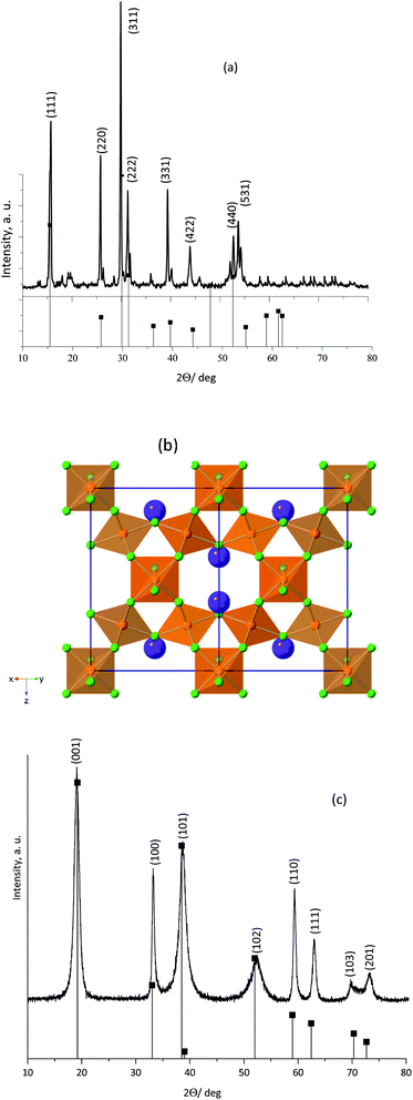
Fig. 1a shows the PXRD pattern obtained for the as-synthesized KNiAlF6 catalyst. The catalyst shows major peaks that match those previously reported for KNiAlF6 (JPC 01-072-1553) and adopts the cubic defect pyrochlore structure in the cubic space group of Fd![[3 with combining macron]](https://www.rsc.org/images/entities/char_0033_0304.gif) m previously reported for this phase (a = 9.92 Å).33 In this pyrochlore structure, Ni and Al are disordered on an octahedral site, (Ni0.5Al0.5)F6, and K+ cations also have octahedral coordination to fluoride. As shown in the crystal structure model in Fig. 1b the structure can be considered as a modified pyrochlore structure (AB2X6) and is constructed of chains of vertex linked (Ni0.5Al0.5)F6 octahedral orientated in layers with alternating orthogonal directions and potassium cations in the channels thereby formed. The small additional reflections in the X-ray pattern were attributed to minor impurities originating from the residual of starting materials which can be removed by washing using deionized water.
m previously reported for this phase (a = 9.92 Å).33 In this pyrochlore structure, Ni and Al are disordered on an octahedral site, (Ni0.5Al0.5)F6, and K+ cations also have octahedral coordination to fluoride. As shown in the crystal structure model in Fig. 1b the structure can be considered as a modified pyrochlore structure (AB2X6) and is constructed of chains of vertex linked (Ni0.5Al0.5)F6 octahedral orientated in layers with alternating orthogonal directions and potassium cations in the channels thereby formed. The small additional reflections in the X-ray pattern were attributed to minor impurities originating from the residual of starting materials which can be removed by washing using deionized water.
On the other hand, Fig. 1c shows the XRD pattern of the bulk nickel hydroxide reference catalyst, which was synthesized at room temperature via precipitation using nickel chloride hexahydrate and sodium hydroxide. The bulk nickel hydroxide catalyst exhibited characteristic peaks at 2θ = 19.20, 32.94, 38.42, 52.9, 59.19, 62.83, and 72.70° corresponding to the crystal planes shown in the pattern and can be assigned to the hexagonal crystal system of the β-Ni(OH)2 phase (JCPDS: 14-0117).
The surface morphology of the as-prepared KNiAlF6 catalyst was investigated using scanning electron microscopy (Fig. 2a and b). Clearly, the catalyst exhibits irregular nanosheets morphology with a roughly average thickness of about 60–70 nm which estimated from the edge of the perpendicularly oriented nanosheets as shown in Fig. S1 (ESI†). On the other hand, the nickel hydroxide reference catalyst prepared at room temperature shows large irregular particles morphology as shown in Fig. 2c.
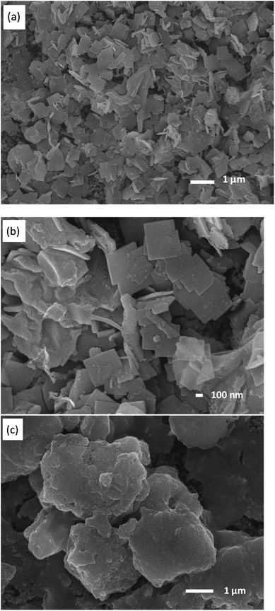 | ||
| Fig. 2 SEM images recorded at a different magnification of the (a and b) KNiAlF6 and (c) bulk Ni(OH)2 catalysts. | ||
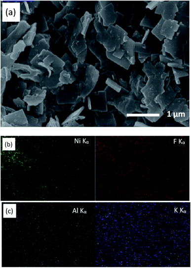
Fig. 3 shows the X-ray mapping elemental analysis using the SEM images obtained for the KNiAlF6 catalyst. The results confirm the presence of K, Ni, Al, and F at a weight ratio of 11.83, 25.62, 10.75, and 51.8 wt%, respectively, which is in good agreement with the molecular formula of KNiAlF6.
Electrochemical characterization of the KNiAlF6 catalyst
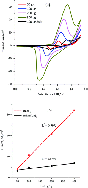
The conductivity of the KNiAlF6 and bulk Ni(OH)2 catalysts was measured using a four-probe conductivity meter using 100 μg of each catalyst spread over 1 cm2. The conductivity values obtained for the KNiAlF6 and bulk Ni(OH)2 catalysts were 1.297 × 10³ and 1.241 × 10² S m−1, respectively. Clearly, the bulk conductivity of the KNiAlF6 nanosheets was almost 10-fold higher than that observed for bulk Ni(OH)2. The cyclic voltammetry (CV) was performed to investigate the electrochemical behavior of the KNiAlF6 catalyst, as shown in Fig. 4a. The CV study was performed at 50 mV s−1 in 1.0 M KOH solution using different catalyst loadings (50, 100, 200, and 300 μg) on the carbon paper support and the results were compared with those of the bulk Ni(OH)2 catalyst (black line).The cyclic voltammograms reveal the characteristic redox peaks commonly observed for nickel-based catalysts, which originate from the Ni(II)/Ni(III) redox couple,34–37 as shown in eqn (5).
| Ni(OH)2 ↔ NiOOH | (5) |
In the case of the KNiAlF6 catalyst at 100 μg loading, the redox peaks are located around 1.45 and 1.25 V vs. HRE for anodic and cathodic reactions, respectively, which are in good agreement with those reported in the literature.34–37 On the other hand, for similar catalyst loading the bulk Ni(OH)2 exhibits redox peaks at 1.55 and 1.28 V for the anodic and cathodic reactions, respectively. The peak separation (ΔE) of the anodic and cathodic reactions (Ea–Ec) equals 0.20 and 0.27 V for KNiAlF6 and bulk Ni(OH)2 catalyst respectively which could be correlated to the higher conductivity of the KNiAlF6 nanosheets.
Interestingly the redox peak currents gradually (and linearly) increase upon increasing the catalyst loading, which confirms the existence of the intrinsically active Ni(II)/Ni(III) redox centers (Fig. 4b). However, the peak separation (ΔE) increases upon increasing the catalyst loading, which was attributed to the reaction being quasi-reversible and the limited diffusion into the thicker film. It is possible to estimate the electroactive surface area (ESA) of the KNiAlF6 catalyst using the charge (Q) area under the reduction peak and eqn (6).
| ESA = Q/mq | (6) |
The influence of the KOH electrolyte concentration on the electrochemical behavior of the KNiAlF6 catalyst was explored using cyclic voltammetry using a catalyst loading of 100 μg as illustrated in Fig. 5. The results show that as the KOH electrolyte concentration increases from 0.1 to 2.0 M, the onset potential of the oxidation peak is significantly shifted to a lower potential due to the Nernst effect in which the potential is inversely proportional to the ion concentration. Therefore, the peak current was increased as the concentration is increased as a result of the increased availability of OH ions. On the other hand, the bulk Ni(OH)2 reference catalyst exhibits an onset potential of 1.45 V vs. HRE in 1.0 M KOH, which is significantly more positive than the onset potential observed for the KNiAlF6 catalyst (1.35 V) under similar conditions. This was attributed to the KNiAlF6 nanosheets having higher conductivity compared to bulk Ni(OH)2, which was confirmed by the conductivity measurement (above) and impedance results shown below.
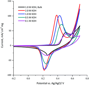 | ||
| Fig. 5 Cyclic voltammograms obtained for 100 μg of the KNiAlF6 and bulk Ni(OH)2 catalysts recorded at a scan rate of 50 mV s−1 in various concentrations of KOH solution (0.1, 0.5, 1.0, and 2.0 M). | ||
The electrocatalytic activity of KNiAlF6 was compared with that of the bulk Ni(OH)2 catalyst during the electro-oxidation of urea in an alkaline solution using CV and CA. As reported by Botte et al.,8,38–40 nickel-based catalysts, in particular metallic nickel, nickel oxides, oxyhydroxides, and phosphates reveal exceptional electrocatalytic activity toward the oxidation of urea due to their redox surface properties and durability. Fig. 6a shows the CV recorded at 50 mV s−1 using 100 μg of KNiAlF6 in comparison to the bulk Ni(OH)2 catalyst in the presence of different concentrations of urea up to 0.33 M in 1.0 M KOH. The cyclic voltammograms show the presence of the urea oxidation peak around 1.55–1.65 V vs. HRE (Fig. 6a). Moreover, the onset potential for urea oxidation at the KNiAlF6 electrode was located at ∼1.35 V vs. HRE, which was negatively shifted by ∼100 mV when compared to the bulk Ni(OH)2 catalyst (black line, Fig. 6a) and could be related to the enhanced electrochemical surface area and the electrical conductivity of KNiAlF6. Besides, the urea oxidation peak current at the KNiAlF6 electrode significantly increases upon increasing the concentration of urea. Further increase of urea concentration above 0.33 M showed a small current enhancement as shown in Fig. S2† possibly because the reaction follows the EC mechanism and the competitive adsorption of urea with hydroxide ion at the catalyst surface decreases the generation rate of NiOOH species that mediates the urea oxidation in the chemical step. Therefore, an optimum ratio of urea/hydroxide concentration should be maintained to achieve the highest urea oxidation current.
As documented in the literature and shown in eqn (1) and (2) above, the electrochemical oxidation of urea in an alkaline solution using nickel-based electrocatalysts occurs through an indirect electrochemical-chemical (EC’) catalyst regeneration reaction mechanism; the active Ni(II) sites are electrochemically oxidized to Ni(III) and then chemically react with urea to regenerate the active Ni(II) sites.41,42 On the other hand, the addition of more urea during the backward scan results in the gradual disappearance of the Ni(III)/Ni(II) cathodic peak around 1.30 V vs. HRE. The decrease in the current observed for the Ni(III)/Ni(II) cathodic peak supports the fact that the EC’ catalyst regeneration reaction mechanism occurred with a lower amount of NiOOH available for the reduction step in the backward scan.41 In addition, the KNiAlF6 catalyst exhibits an increase in the peak current at 1.65 V vs. HRE and reaches ∼395 mA cm−2 mg−1 at a urea concentration of 0.33 M, while that observed for the bulk Ni(OH)2 catalyst was 238 mA cm−2 mg−1.
The effect of the KNiAlF6 catalyst loading on the electrochemical activity of urea oxidation is presented in Fig. 6b. The urea oxidation current gradually increases upon increasing the KNiAlF6 catalyst loading up to 150 μg due to the increase in the number of available Ni(II)/Ni(III) active sites responsible for the urea oxidation reaction. However, at a high KNiAlF6 catalyst loading (>150 μg, data not shown) the oxidation current starts to saturate due to the increase in the film thickness and the limited accessibility to the Ni(II)/Ni(III) active sites.
The corresponding Tafel slope of KNiAlF6 and bulk Ni(OH)2 catalysts as obtained from the cyclic voltammograms (Fig. 6a) is shown in Fig. 6c. The obtained Tafel slope in 1.0 M KOH and 0.33 M urea solution was equal 22 and 38 mV dec−1 for KNiAlF6 and bulk Ni(OH)2 respectively which indicates much faster reaction kinetics of urea oxidation at KNiAlF6 nanosheets than bulk Ni(OH)2 electrode. This activity and kinetics enhancement can be attributed to the enhanced conductivity and ESA of the KNiAlF6 electrode toward the urea oxidation reaction due to the electro-oxidation of the KNiAlF6 catalyst in an alkaline solution toward NiOOH species that oxidize urea via an EC’ mechanism.41
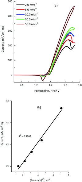
Cyclic voltammetry was recorded at various scan rates from 2.0 to 50.0 mV s−1 to investigate the effect of the scan rate on the electro-oxidation of urea using the KNiAlF6 catalyst.
The cyclic voltammograms clearly show that the urea anodic oxidation current increases with the scan rate. In addition, Fig. 7b shows the linear relationship observed between the anodic peak current (ipeak) and the square root of the scan rate [R2 = 0.9862], which confirmed the diffusion-controlled urea electro-oxidation reaction occurred using the KNiAlF6 catalyst in an alkaline solution.37,40,41 However, the slight shift in the urea wave potential towards a more positive value upon increasing the scan rate could be related to change in the reaction kinetics due to the adsorption of urea molecules on the active Ni(III) sites at higher scan rates as reported in the literature.39–42
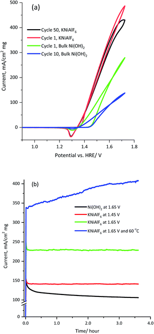
Fig. 8 shows the multicycle (50 cycles) and long term chronoamperometry electrolysis of a 1.0 M KOH solution containing 0.33 M urea using the KNiAlF6 catalyst in comparison to the bulk Ni(OH)2 catalyst at various applied potentials. The cyclic voltammograms of the KNiAlF6 electrode (Fig. 8a) show remarkable stability where the urea oxidation current slightly decreased at 1.65 V vs. HRE after prolonged cycling. On the other hand, the bulk Ni(OH)2 catalyst exhibits a ∼50% reduction in the urea oxidation current after 50 cycles. In addition, according to chronoamperometry results shown in Fig. 8b and after the double layer capacitance initial current decay, the electrolysis current reaches a steady-state value without any apparent decay during the extended urea electrolysis process at all applied potentials studied.
The electrolysis steady-state current is significantly enhanced upon increasing the applied potential; the KNiAlF6 catalyst mass activity reaches ∼230 mA cm−2 mg−1 at 1.65 V vs. HRE after 3 hour electrolysis, which is substantially higher than that obtained using the bulk Ni(OH)2 catalyst (∼107 mA cm−2 mg−1). Furthermore, the catalyst stability for urea oxidation was performed at 1.65 V and 60 °C as shown in Fig. 8b (blue curve). The KNiAlF6 catalyst shows outstanding stability under higher temperature and the urea oxidation current continuously increased recording about 400 mA cm−2 mg−1 after 3 hour electrolysis. This confirmed the superior electrochemical activity and stability of the KNiAlF6 catalyst during urea electrolysis in an alkaline solution compared to those of the bulk Ni(OH)2 catalyst, as well as the that observed for other nickel-based catalysts published in the literature, as shown in Table 1. It worth comparing our KNiAlF6 nanosheets with that of 2D pure Ni(OH)2 nanosheets catalyst reported by Botte et al.8 because of similar nanosheets morphology.
| Anode materials | Mass activity (mA cm−2.mg) | Scan rate mV s−1 | Reference |
|---|---|---|---|
| β-Ni(OH)2-CNTs (80 °C) via a facile hydrothermal reaction | 98.5 mA cm−2 at 0.6 V, cata. Loading = 0.57 mg cm−2, 172.80 mA cm−2 mg−1 | 50 mV s−1 | 20 |
| S-doped β-Ni(OH)2 nanosheet via treatment by with an H2S flow at elevated temperature | ∼37 mA cm−2 at 0.55 V | 50 mV s−1 | 43 |
| Ni3+-rich Ni(OH)2/C–NH2/GCE | 91.72 mA cm−2 at 0.61 V | 50 mV s−1 | 44 |
| Ni foam-supported OM-NiO nanosheets | 450 mA cm−2 mg−1 at 0.6 V | 10 mV s−1 | 45 |
| Mesoporous nickel phosphide (Ni–P) via a facile solvothermal synthesis | ∼110 mA cm−2 at 0.55 V | 10 mV s−1 | 46 |
| Mesoporous spinel NiCo2O4 nanostructures | ∼90 mA cm−2 mg−1 at 0.6 V | 10 mV s−1 | 47 |
| Ni nanowires | 80 mA cm−2 at 0.6 V, loading (1.3 ± 0.1 mg cm−2), 61.53 mA cm−2 mg−1 | 10 mV s−1 | 37 |
| Nickel hydroxide nanoflakes | ∼1295 mA cm−2 mg−1 at 0.5 V, 1.0 M NaOH | 50 mV s−1 | 32 |
| KNiAlF6 nanosheets | ∼395 mA cm−2 mg−1 at 0.6 V | 50 mV s−1 | This work |
Interestingly as revealed by the cyclic voltammetry study and at similar urea concentration, our KNiAlF6 nanosheets revealed a significant performance (∼395 mA cm−2 mg−1, 1.0 M KOH) for urea oxidation in comparison with that of Ni(OH)2 nanosheets (154 mA cm−2 mg−1, 5.0 M KOH) as reported by Botte et al.8 Moreover from the chronoamperometry study, the mass activity of our KNiAlF6 nanosheets reaches ∼230 mA cm−2 mg−1 (1.0 M KOH) while the Ni(OH)2 nanosheets recorded about 100 mA cm−2 mg−1 in 5.0 M KOH solution. The electrochemical activity of urea oxidation for our NiAlF6 nanosheets is more than 2 fold higher than that of Ni(OH)2 nanosheet reported by Botte et al.8 and this could be related to the better conductivity/surface area due to the incorporation of aluminum ions in the nickel-based structure frame.
However, the Ni(OH)2 nanoflakes electrocatalyst prepared by liquid crystal template previously reported by Ghanem et al.32 showed a higher electrochemical mass activity (∼1295 mA cm−2 mg−1) than the current KNiAlF6 nanosheets catalyst. This presumably because the former catalyst has a higher surface area than the KNiAlF6 nanosheets.
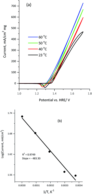
Fig. 9a illustrates the influence of the reaction temperature on the electrocatalytic activity of 100 μg of the KNiAlF6 catalyst in a 1.0 M KOH solution containing 0.33 M urea.
Clearly, the urea electrolysis mass activity observed at 1.65 V vs. HRE was significantly enhanced upon increasing the temperature increase and reaches ∼550 mA cm−2 mg−1 at 60 °C (Fig. 9a). This indicates that the urea oxidation reaction on the KNiAlF6 nanosheets catalyst surface was further activated upon increasing the temperature. Moreover, the onset potential shifts from 1.35 to 1.31 V vs. HRE upon increasing the temperature from 23 to 60 °C whilst maintaining the Ag/AgCl reference electrode at room temperature (23 °C). Furthermore, the apparent activation energy for urea electro-oxidation using the KNiAlF6 catalyst in 0.33 M urea/1.0 M KOH can be calculated by plotting the logarithm of current density vs. reciprocal of the absolute temperature, as shown in Fig. 9b. According to the Arrhenius equation (eqn (7)),37,48,49 the plot points are reasonably fitted by a straight line with the correlation coefficient is very close to unity (R2 = 0.974), where K is the reaction rate constant, A is the Arrhenius constant, Ea is the activation energy, R is the gas constant, and T is the absolute temperature.
| K = Ae−Ea/RT | (7) |
The value obtained for the activation energy (Ea) from the slope of the straight line was found to be 4.02 kJ mol−1, which is significantly low when compared to for example nickel-based nanosheets grown on reduced graphene support (10.35 kJ mol−1) and those reported in other published studies related to urea oxidation on nickel-based materials50,51 and methanol oxidation.49,52
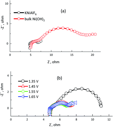
Electrochemical impedance spectroscopy (EIS) was used to determine the electrode/electrolyte interface charge resistance of the electrochemical urea oxidation reaction using the KNiAlF6 catalyst in comparison with that of bulk Ni(OH)2 catalyst in 1.0 M KOH and in the presence of 0.33 M urea. Fig. 10a and b show the Nyquist plots obtained for the KNiAlF6 nanosheets and bulk Ni(OH)2 catalysts at 1.65 V and the EIS measurements recorded at various potentials (1.35–1.65 V vs. HRE), respectively. As shown in the inset in Fig. 10a, the impedance spectra obtained for the KNiAlF6 nanosheets and bulk Ni(OH)2 catalysts can be fitted to an equivalent circuit model involving a series combination of ohmic resistance (Rs), a generalized finite Warburg resistance with its short circuit (Rct1–W‖CPE1). The high frequency relates to the Ni(OH)2/NiOOH reaction involving indirect urea oxidation, which is connected in series with the parallel resistance-constant phase elements (Rct2 and CPE2, respectively) and at a low frequency associated with the direct urea electro-oxidation reaction. The equivalent circuit model is shown in the inset of Fig. 10a is similar to those previously reported for the electrochemical urea oxidation reaction.36,53,54 The constant phase element (CPE) corresponds to the double-layer capacitance and was used to replace the pure capacitor based on previously reported models, which attribute the CPE to the frequency distribution of the capacitance. This replacement may arise due to the electrode surface inhomogeneity, roughness, reactivity, porosity, and surface/normal distribution of the electrode elements.55
Fig. 10a shows the radii of the arc observed in the EIS Nyquist plots obtained for the KNiAlF6 electrode are lower than those of the bulk Ni(OH)2 catalyst, which indicates that the KNiAlF6 catalyst possesses a smaller Rct indicating higher electrode conductivity and enhanced electrochemical urea oxidation performance. Table 2 clearly shows that the resistor (Rs) representing the electrolyte resistance stays almost constant with an average value of 4.9 Ω, while the Rct2 values observed for the KNiAlF6 nanosheets and bulk Ni(OH)2 electrodes were found to be 1.662, and 12.61 Ω, respectively. The Rct2 values for the second semicircle (corresponding to the direct urea electro-oxidation reaction) at various polarization potentials are plotted in Fig. 10b and the corresponding impedance parameters are summarized in Table 2. It can be seen that the semicircle diameter and Rct2 values are significantly decreased as the oxidation potential was shifted from 1.35 to 1.65 V vs. HRE, which suggests that the urea electro-oxidation process at the KNiAlF6 nanosheet electrode is significantly improved at higher potential, which is consistent with the cyclic voltammetry results.
| Potential vs. HRE (V)/catalyst | ISE parameters | |||||
|---|---|---|---|---|---|---|
| Rs | Rct1 (Ω) | CPE1 (Q1) | Rct2 (Ω) | CPE2 (Q2) | Warburg | |
| 1.65/Bulk | 5.30 | 1.37 | 2.129 × 10⁻⁴ | 12.61 | 0.0103 | 0.125 |
| 1.65/KNiAlF6 | 4.88 | 1.866 | 0.0219 | 0.239 | 0.00159 | 1.659 |
| 1.55/KNiAlF6 | 4.88 | 0.223 | 0.0014 | 1.662 | 0.02361 | 1.958 |
| 1.45/KNiAlF6 | 4.89 | 1.906 | 0.0199 | 0.303 | 0.00154 | 3.323 |
| 1.35/KNiAlF6 | 5.00 | 0.796 | 0.0114 | 5.39 | 0.01687 | 9.447 × 10¹¹ |
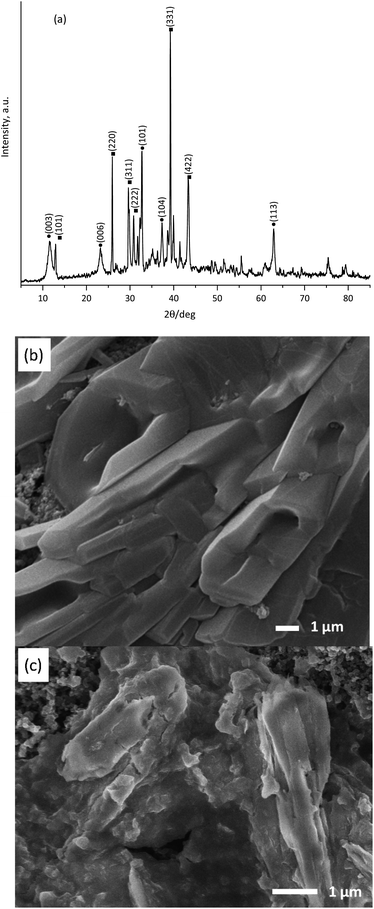
After the chronoamperometry measurement of the urea electrolysis process, the used KNiAlF6 catalyst was characterized using XRD and scanning electron microscopy to identify the changes in the KNiAlF6 catalyst crystal structure and surface morphology. Fig. 11a shows the XRD pattern obtained for the KNiAlF6 catalyst after being used in the urea electrochemical electrolysis process in 0.33 M urea/1.0 M KOH solution at 0.6 V for 3 hours at 23 °C. The XRD pattern revealed that the peaks match the characteristic peaks for both crystalline KNiAlF6 (JPC: 01-072-1553) and amorphous Ni(OH)2/NiOOH (JPC: 01-089-7111), which confirms the partial transformation of KNiAlF6 to Ni(OH)2/NiOOH during the urea electrolysis process and the electrochemical reaction with the 1.0 M KOH solution. Fig. 11b and c show the SEM images of the KNiAlF6 nanosheets surface morphology after been used in urea electrolysis process that conducted at 1.65 V in 0.33 M urea/1.0 M KOH solution for three hours at 23 and 60 °C, respectively. Interestingly, the SEM images reveal a significant change in the KNiAlF6 nanosheets morphology where the nanosheets are swelled and coalesced forming a continuous structure. However, the nanosheets' edges are still observable to some extent and the catalyst maintained its electrocatalytic activity for urea oxidation as shown above by chronoamperometry in Fig. 8b. The corresponding X-ray elemental mapping and composition wt% of the KNiAlF6 catalyst after been used in urea oxidation at 60 °C for 3.0 hours are shown in Fig. S3 and Table S1† respectively. The EDX composition analysis of the KNiAlF6 catalyst shows the wt% of K, Al, and Ni is slightly changed after been used in urea electrolysis. On the other hand, fluorine percentage is significantly decreased from 51.8 to 28.55 wt% while oxygen has been increased to 28.27 wt%. The element composition change could be related to the partial change in the phase structure of KNiAlF6 to Ni(OH)2/NiOOH after the catalyst been used in urea oxidation as confirmed by the X-ray results shown in Fig. 11a.
Conclusions
In summary, the catalyst of KNiAlF6 nanosheets was successfully prepared using solid-phase synthesis and employed as an electrocatalyst for urea electrolysis conducted in alkaline media. The crystal structure, morphology, conductivity, and composition analysis has been carefully characterized and the results revealed that the formation of KNiAlF6 nanosheets with cubic defect pyrochlore structure and roughly average thickness of 60-70 nm and conductivity of 1.297 × 10³ S m−1. The obtained KNiAlF6 nanosheets catalyst exhibited significantly enhanced conductivity and electrochemical activity during the urea oxidation reaction in alkaline media. Urea oxidation peak current of ∼395 mA cm−2 mg−1 at 1.65 V vs. HRE, oxidation onset potential of 1.35 V vs. HRE and Tafel slope of 22 mV dec−1, reaction activation energy of 4.02 kJ mol−1 and, steady-state mass activity of 230 and 107 mA cm−2 mg−1 were achieved. Low charge transfer resistance and long-term urea oxidation durability at higher temperature of the KNiAlF6 nanosheets are revealed from the impedance and chronoamperometry characterizations. After the catalyst is been used in urea oxidation, the crystal structure and surface morphology of the KNiAlF6 nanosheets were significantly changed due to the partial transformation to Ni(OH)2/NiOOH structure, however, the electrochemical activity was maintained during the extended use in the urea electrolysis process.Conflicts of interest
The authors declare no conflict of interest.Acknowledgements
The authors are grateful to the Deanship of Scientific Research at King Saud University for funding this research group No. RG-1437-015 and thank the Researchers Support & Services Unit (RSSU) for the manuscript proofreading. S. Aladeemy thanks the students support program provided by K.A.CARE.Notes and references
- I. Staffell, D. Scamman, A. V. Abad, P. Balcombe, P. E. Dodds, P. Ekins, N. Shahd and K. R. Warda, Energy Environ. Sci., 2019, 12, 463 RSC.
- W. Zhang, W. Lai and R. Cao, Chem. Rev., 2017, 117, 3717 CrossRef CAS.
- W. Xu, Z. Wu and S. Tao, Energy Technol., 2016, 4, 1329 CrossRef CAS.
- P. Joghee, J. N. Malik, S. Pylypenko and R. O'Hayre, MRS Energy Sustain., 2015, 2, 1–31 CrossRef.
- B. K. Boggs, R. L. King and G. G. Botte, Chem. Commun., 2009, 32, 4859–4861 RSC.
- J. C. Wright, A. S. Michaels and A. J. Appleby, AIChE J., 1986, 32, 1450–1458 CrossRef CAS.
- W. Simka, J. Piotrowski and G. Nawrat, Electrochim. Acta, 2007, 52, 5696–5703 CrossRef CAS.
- D. Wang, W. Yan and G. G. Botte, Electrochem. Commun., 2011, 13, 1135–1138 CrossRef CAS.
- W. Yan, D. Wang and G. G. Botte, Electrochim. Acta, 2012, 61, 25–30 CrossRef CAS.
- E. Taha, S. T. Eisa, H. O. Mohamed, M. A. Abdelkareem, A. Allaguid, H. Alawadhib and K.-J. Chae, J. Power Sources, 2019, 417, 159 CrossRef.
- R. Lan, S. Tao and J. T. S. Irvine, Energy Environ. Sci., 2010, 3, 438 RSC.
- W. Yan, D. Wang and G. G. Botte, Appl. Catal., B, 2012, 127, 221 CrossRef CAS.
- D. Wang, W. Yan, S. H. Vijapur and G. G. Botte, Electrochim. Acta, 2013, 89, 732 CrossRef CAS.
- W. Huang, H. Wang, J. Zhou, J. Wang, P. Duchesne, D. Muir, P. Zhang, N. Han, F. Zhao, M. Zeng, J. Zhong, C. Jin, Y. Li, S. Lee and H. Dai, Nat. Commun., 2015, 6, 10035 CrossRef CAS.
- A. M. Al-Enizia, M. A. Ghanem, A. A. El-Zatahry and S. S. Al-Deyab, Electrochim. Acta, 2014, 137, 774 CrossRef.
- J. Li, Y. Zuo, J. Liu, X. Wang, X. Yu, R. Du, T. Zhang, M. F. Infante-Carrió, P. Tang, J. Arbiol, J. Llorca, Z. Luo and A. Cabot, J. Mater. Chem. A, 2019, 7, 22036 RSC.
- D. Wang, W. Yan, S. H. Vijapur and G. G. Botte, Electrochim. Acta, 2013, 89, 732 CrossRef CAS.
- S. Periyasamy, P. Subramanian, E. Levi, D. Aurbach, A. Gedanken and A. Schechter, ACS Appl. Mater. Interfaces, 2016, 8, 12176 CrossRef CAS.
- M. Mazloum-Ardakani, V. Eslami and A. Khoshroo, Mater. Sci. Eng., B, 2018, 229, 201 CrossRef CAS.
- Q. Gan, X. Cheng, J. Chen, D. Wang, B. Wang, J. Tain, T. Isimjan and X. Yang, Electrochim. Acta, 2019, 301, 47 CrossRef CAS.
- W. Yan, Nickel-based Catalysts for Urea Electro-oxidation, PhD thesis, Ohio University, 2014.
- X. Guo, H. Liu, Y. Xue, J. Chen, X. Wan, J. Zhang, Y. Liu, A. Yuan, Q. Kong and H. Fan, Eur. J. Inorg. Chem., 2019, 32, 3719 CrossRef.
- J. Huang, D. Cao, T. Lei, S. Yang, X. Zhou, P. Xu and G. Wang, Electrochim. Acta, 2013, 111, 713 CrossRef CAS.
- A. Béléké and M. Mizuhata, J. Power Sources, 2010, 195, 7669 CrossRef.
- C. Faure, C. Delmas, M. Fouassier and P. Willmann, J. Power Sources, 1991, 35, 249 CrossRef CAS.
- S. Chou, F. Cheng and J. Chen, Eur. J. Inorg. Chem., 2005, 2005, 4035 CrossRef.
- L. Guerlou-Demourgues, C. Tessier, P. Bernard and C. Delmas, J. Mater. Chem., 2004, 14, 2649 RSC.
- C. Lin, Z. Gao, F. Zhang, J. Yang, B. Liu and J. Jin, J. Mater. Chem. A, 2018, 6, 13867 RSC.
- M. A. Abdelkareem, Y. Al Haj, M. Alajami, H. Alawadhi and N. A. M. Barakat, J. Environ. Chem. Eng., 2018, 6, 332 CrossRef CAS.
- N. A. M. Barakat, H. M. Moustafa, M. M. Nassar, M. A. Abdelkareem, M. S. Mahmoud, A. A. Almajid and K. A. Khalil, Electrochim. Acta, 2015, 182, 143 CrossRef CAS.
- R. M. Abdel Hameed and S. S. Medany, J. Colloid Interface Sci., 2017, 508, 291 CrossRef CAS.
- M. A. Ghanem, A. M. Al-Mayouf, J. P. Singh and P. Arunachalam, Electrocatal, 2017, 8, 16 CrossRef CAS.
- D. Babel, G. Pausewang and W. Viebahn, Z. Naturforsch. Teil B Anorg. Chem. Org. Chem. Biochem. Biophys. Biol., 1967, 22, 1219 CAS.
- M. Alsabet, M. Grdeń and G. Jerkiewicz, Electrocatal, 2015, 6, 60 CrossRef CAS.
- Y. J. Shih, Y. H. Huang and C. P. Huang, Electrochim. Acta, 2018, 263, 261 CrossRef CAS.
- F. Guo, K. Ye, M. Du, X. Huang, K. Cheng, G. Wang and D. Cao, Electrochim. Acta, 2016, 210, 474 CrossRef CAS.
- W. Yan, D. Wang, L. A. Diaz and G. G. Botte, Electrochim. Acta, 2014, 134, 266 CrossRef CAS.
- V. Vedharathinam and G. G. Botte, J. Phys. Chem. C, 2014, 118, 21806–21812 CrossRef CAS.
- D. A. Daramola, D. Singh and G. G. Botte, J. Phys. Chem. A, 2010, 114, 11513 CrossRef CAS.
- D. Wang, W. Yan, S. H. Vijapur and G. G. Botte, J. Power Sources, 2012, 217, 498 CrossRef CAS.
- V. Vedharathinam and G. G. Botte, Electrochim. Acta, 2012, 81, 292 CrossRef CAS.
- E. Lohrasbi and M. Asgari, Adv. Anal. Chem., 2015, 5, 9 Search PubMed.
- X. Zhu, X. Dou, J. Dai, X. An, Y. Guo, L. Zhang, S. Tao, J. Zhao, W. Chu, X. C. Zeng, C. Wu and Y. Xie, Angew. Chem., Int. Ed., 2016, 55, 12465 CrossRef CAS.
- D. Wang, S. Liu, Q. Gan, J. Tian, T. T. Isimjan and X. Yang, J. Electroanal. Chem., 2018, 829, 81 CrossRef CAS.
- M. S. Wu, G. W. Lin and R. S. Yang, J. Power Sources, 2014, 272, 711 CrossRef CAS.
- R. Ding, X. Li, W. Shi, Q. Xu, L. Wang, H. Jiang, Z. Yang and E. Liu, Electrochim. Acta, 2016, 222, 455 CrossRef CAS.
- R. Ding, L. Qi, M. Jia and H. Wang, Nanoscale, 2014, 6, 1369 RSC.
- N. Radenahmad, A. Afif, P. I. Petra, S. M. H. Rahman, S. G. Eriksson and A. K. Azad, Renewable Sustainable Energy Rev., 2016, 57, 1347 CrossRef CAS.
- J. L. Cohen, D. J. Volpe and H. D. Abruña, Phys. Chem. Chem. Phys., 2007, 9, 49 RSC.
- A. Zaher, W. M. A. El Rouby and N. A. M. Barakat, Int. J. Hydrogen Energy, 2020, 45, 8082 CrossRef CAS.
- B. Li, C. Song, J. Jun, Y. Ke, Y. Kui, C. Kaizhu, D. Cao and G. Wang, Int. J. Hydrogen Energy, 2020, 45, 10569 CrossRef CAS.
- A. Nouralishahi, Y. Mortazavi, A. A. Khodadadi, M. Choolaei, L. T. Thompson and B. A. Horri, Appl. Surf. Sci., 2019, 335, 467 Search PubMed.
- R. K. Singh and P. Subramanian, ChemElectroChem, 2017, 4, 1037 CrossRef CAS.
- R. M. Abdel Hameed and S. S. Medany, J. Colloid Interface Sci., 2018, 513, 536 CrossRef CAS.
- R. K. Singh, R. Devivaraprasad, T. Kar, A. Chakraborty and M. Neergat, J. Electrochem. Soc., 2015, 162, F489 CrossRef CAS.
Footnote |
| † Electronic supplementary information (ESI) available. See DOI: 10.1039/d0ra10814f |
| This journal is © The Royal Society of Chemistry 2021 |

