 Open Access Article
Synthesis of ZnIn2S4@Co3S4 particles derived from ZIF-67 for photocatalytic hydrogen production†
Ganyu Wangab,
Wenqian Chen *ab,
Yu Zhangab,
Qinshang Xuab,
Yirui Liab,
Maw Lin Fooc and
Liang Tang
 *ab
*ab
aKey Laboratory of Organic Compound Pollution Control Engineering, Ministry of Education, Shanghai University, Shanghai 200444, PR. China
bSchool of Environmental and Chemical Engineering, Shanghai University, Shanghai 200444, PR China. E-mail: wenqianchen@shu.edu.cn; tang1liang@shu.edu.cn
cDepartment of Chemistry, National University of Singapore, 117543, Singapore
First published on 1st March 2021
Abstract
In this work, ZIF-67 derivative Co3S4 with diamond dodecahedron structure was firstly synthesized via a series of reactions, and ZnIn2S4@Co3S4 heterostructures with adjustable band gaps were successfully obtained through a simple hydrothermal method. Consequently, ZnIn2S4@Co3S4 heterostructures have significantly enhanced visible light absorption and improved photocatalytic efficiency, among which the ZC-5 composite exhibits the highest photocatalytic hydrogen production rate up to 4261 μmol g−1 h−1 under simulated sunlight, to be approximately 4.8 times higher than that of pure ZnIn2S4. The enhanced photocatalytic activity can be attributed to faster electron transfer and more efficient electron–hole pairs separation derived from the heterostructures which form at the interface between Co3S4 and ZnIn2S4. Thus, this study provides a good strategy for photocatalytic hydrogen production without precious metals using heterostructures.
1. Introduction
Due to increasingly serious environmental pollution caused by the burning of fossil fuels and the increasing global demand for energy, it is necessary to explore a clean and renewable alternative.1,2 Hydrogen energy generated by simulated solar photocatalysis reaction is an effective means to solve the current problem.3,4 In 1972, Fujishima et al. discovered that water could be decomposed into hydrogen under ultraviolet light by photoelectrochemical technology with the help of titania.5 Since then, photocatalysts based on semiconductor materials for hydrogen production utilizing solar energy have been widely studied.6 So far, researchers have invented and developed various photocatalysts that respond to visible light, such as oxides (ZnO7), nitride (g-C3N4 (ref. 8)), and sulfides (CdS,9 MoS2 (ref. 10)).Zinc indium sulfide (ZnIn2S4), as a ternary metal chalcogenide, is considered as a prominent photocatalyst due to its suitable band gap, good visible light response, environmental friendliness and relatively excellent chemical stability.11 In recent years, ZnIn2S4 has been widely applied in photocatalytic hydrogen production,12 carbon dioxide reduction,13 dye degradation14 and so on. However, for photocatalytic hydrogen evolution, ZnIn2S4 still faces some challenges to increase the activity, such as how to enhance the response of visible light and improve the transfer and separation efficiency of photo-generated charge carriers. A number of strategies have been explored to modify ZnIn2S4 for potential practical applications including structure and morphology controlling (nanoparticle,15 nanosheets,16 microsphere17), element doping (copper,18 nitrogen,19 alkaline-earth metal20), co-catalyst modifying (Au@Pt,21 WS2,22 MoS2 (ref. 23)) and heterojunction construction (CeO2/ZnIn2S4,24 ZnS/ZnIn2S4 (ref. 25)). For example, Shen et al.26 reported that hexagonal ZnIn2S4 photocatalysts with different crystallinity and morphology were synthesized under different mediated conditions, exhibiting different photocatalytic properties. Shen et al.18 prepared a series of ZnIn2S4 doped with different amounts of copper with improved photocatalytic activity. An et al.21 designed a novel ZnIn2S4 which loaded core–shell Au@Pt on nanosheets surface, showing outstanding visible hydrogen production ability. However, high prices, poor durability and low abundance limit the use of precious metals on a large scale. Among all the modifications, it is preferable to build heterojunction structures by integrating ZnIn2S4 with other semiconductors without noble metals, which could stagger the arrangement of energy levels, thus accelerating charge separation and transmission.
As an emerging porous crystal materials, metal–organic frameworks (MOFs) consisted of metal units and organic ligands have an advantage in large surface areas, adjustable pore sizes and myriad of crystal structures, which can supply abundant active sites and promote charge transfer.27 However, MOFs are not ideal in terms of cyclic stability and still need to be modified.28 At present, MOFs have been widely used as precursors or templates to prepare functional materials with specific components and complex structures, such as porous carbon materials,29 metal oxides30 and metal sulfides.31 Meanwhile, this process is easily achieved by means of hydrothermal or calcination. The obtained functional materials continue the virtues of MOFs and exhibit superior performance.32,33 Moreover, when the energy band structures of the two components are well matched, MOF derivatives can promote electron transfer and photo-generated charge carrier separation through contact surfaces to improve activity.34,35 Therefore, MOF derivatives are widely applied in environmental energy catalysis.
Therefore, in this study, a novel ZnIn2S4@Co3S4 composite photocatalyst based on ZIF-67 derivative is reported. First, ZIF-67 is converted into Co3S4 by two-step method, and then ZnIn2S4 nanosheets are grown on the surface of Co3S4 in the hydrothermal process, forming heterogeneous structures between ZnIn2S4 and Co3S4, which promote charge transfer and separation. As expected, the fabricated ZnIn2S4@Co3S4 composite photocatalysts show better photocatalytic hydrogen production performance compared with ZnIn2S4. Moreover, the effects of different coupling amount of Co3S4 on the photocatalytic hydrogen production performance are studied. In addition, according to the ZnIn2S4@Co3S4 energy level structure, a possible photocatalytic hydrogen evolution mechanism is proposed.
2. Experimental section
2.1. Chemicals
Cobalt nitrate hexahydrate (Co(NO3)2·6H2O, RG), indium chloride tetrahydrate (InCl3·4H2O, RG), thioacetamide (TAA, RG), 2-methylimidazole (2-MeIM, RG), triethanolamine (TEOA) were all obtained from Titan Technology. Zinc nitrate hexahydrate (Zn(NO3)2·6H2O, RG) was purchased from Sinopharm Chemical Reagent Co. Ltd. All chemicals and materials were used directly without further purification.2.2. Synthesis of ZnIn2S4@Co3S4 hollow composites
Co3S4 was synthesized according to a modified method reported in the literature.36 It can be divided into three parts. Firstly, the synthesis of ZIF-67, 2-methylimidazole (7.88 g) was dissolved in 60 mL of methanol to form a transparent solution, which was quickly poured into another 60 mL of methanol solution dissolving Co(NO3)2·6H2O (3.48 g), and the mixture was stirred vigorously for 1 min. Then, the mixture was kept at room temperature for 24 h. The purple precipitation was obtained by centrifugation, washed at least three times and vacuum dried at 60 °C for 12 h. Secondly, 80 mg of ZIF-67 was dispersed in 20 mL of absolute ethanol by ultrasound for 20 min. Then another 20 mL solution of absolute ethanol containing TAA (0.12 g) was added. Thereafter, the mixture was transferred to a 50 mL Teflon-lined stainless-steel autoclave and reacted at 120 °C for 4 h. The hollow Co3S4 was obtained by centrifugation, washing and drying. Finally, they were annealed in N2 atmosphere at 350 °C for 2 h with a heating rate of 1 °C min−1.ZnIn2S4@Co3S4 nanocomposites were prepared by a simple hydrothermal reaction. The Co3S4 content is 2%, 5%, 10%, 20% respectively and they were labeled as ZC-X (X = the percentage of Co3S4). In a typical experimental procedure, a certain amount of Co3S4, 1.0 mmol Zn(NO3)2·6H2O (0.297 g), 2.0 mmol InCI3·4H2O (0.586 g) and 6.0 mmol TAA (0.45 g) was dissolved in 60 mL deionized water and evenly dispersed by stirring for 60 min. After that, the mixture was transferred to a 100 mL Teflon-lined stainless-steel autoclave and reacted at 160 °C for 12 h. Finally, the sediment was separated by centrifuge, washed with deionized water and absolute ethanol at least three times and dried under vacuum overnight at 60 °C. The above synthesis process is shown in Scheme 1. To make comparisons, the pure ZnIn2S4 was synthesized at the same reaction condition without Co3S4.
2.3. Materials characterization
An X-ray diffractometer (Bruker D8 Advance XRD) was used to characterize the crystal structure of the synthesized samples by Cu Kα radiation operated at 40 kV and 40 mA in the range of 5° to 80°. The morphologies and microstructures of prepared photocatalysts were observed by scanning electronic microscopy (Gemini SEM300), operating at 15 kV equipped with energy-dispersive X-ray spectra (EDS). The elemental composition and valence of sample surface were obtained by K-Alpha + X-ray photoelectron spectrometer (XPS) with mono Al Kα radiation. Ultraviolet-visible (UV-vis) diffuse reflectance spectra (DRS) of prepared samples were performed by an UV-vis spectrophotometer (UV-2600, Shimadzu, Japan) with the background of BaSO4. The photoluminescence (PL) spectra were measured by Gangdong Technology F-320 PL spectrophotometer with the excitation wavelength of 260 nm. BeiShiDe Micropore Analyzer 3H-2000PM were employed to test the Brunauer–Emmett–Teller (BET) surface areas of the samples.2.4. Photoelectrochemical properties measurements
The electrochemical workstation (CHI660E Instruments) was used to analyze the photoelectrochemical properties of the obtained samples by amperometric i–t curves and electrochemical impedance spectroscopy (EIS) and Mott–Schottky analysis. The tests were carried out with a conventional three-electrode system consisting of platinum-sheet electrode, saturated calomel electrode (SCE) and conductive glass coated with sample powder, which served as counter electrode, reference electrode and working electrode, respectively. The working electrode was prepared by a method which is similar to the literature reported by Ling et al.37 The ca. 10 mg catalyst and 5 w% solution of polyvinylidene fluoride in N-methyl pyrrolidone solution were fully grinded in a ratio of 9![[thin space (1/6-em)]](https://www.rsc.org/images/entities/char_2009.gif) :
:![[thin space (1/6-em)]](https://www.rsc.org/images/entities/char_2009.gif) 1, and then coated on the conductive surface of conductive glass for vacuum drying at 60 °C for 12 h. Meanwhile, 0.5 M Na2SO4 solution was used as the electrolyte. The amperometric i–t curves was tested by the intermittent irradiation of a 300 W Xe lamp (CEL-HXF300). An impedance-potential model was applied to the Mott–Schottky measurement, where the voltage range was −1.5 to 1.5 V. The EIS tests were done in a dark condition with a frequency ranging from 10−2 and 105 Hz.
1, and then coated on the conductive surface of conductive glass for vacuum drying at 60 °C for 12 h. Meanwhile, 0.5 M Na2SO4 solution was used as the electrolyte. The amperometric i–t curves was tested by the intermittent irradiation of a 300 W Xe lamp (CEL-HXF300). An impedance-potential model was applied to the Mott–Schottky measurement, where the voltage range was −1.5 to 1.5 V. The EIS tests were done in a dark condition with a frequency ranging from 10−2 and 105 Hz.
2.5. Photocatalytic H2 production experiments
The photocatalytic hydrogen production reactions were carried out in a 250 mL closed quartz glass reactor, which was irradiated by a 300 W Xe lamp (PLS-SXE 300, Perfectlight, Beijing, λ ≧ 350 nm). Generally, 40 mg of photocatalyst was dispersed into 60 mL homogeneous solution containing 50 mL deionized water and 10 mL TEOA as sacrificial agent with constantly stirring. Before the photocatalytic reaction, the gas in the system was completely evacuated and the temperature of hydrogen production reaction was controlled at 5 °C by a cold-water circulation system. The photocatalytic hydrogen evolution rate was collected by a Shimadzu GC-2014C gas chromatograph.3. Results and discussions
3.1. Structures and compositions
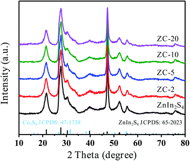
The X-ray diffraction (XRD) patterns of pure ZnIn2S4 and ZC-X (X = 2–20) composites with different proportions of Co3S4 are shown in Fig. 1. The characteristic peaks of prepared pure ZnIn2S4 are present at 21.6°, 27.7°, 39.9°, 47.2°, 52.4° and 55.6°, which is consistent with (006), (102), (108), (110), (116), and (202) crystal planes matching hexagonal ZnIn2S4 (JCPDS no. 65-2023).38 Meanwhile, ZIF-67 as a sacrifice template is successfully synthesized which can be proved by XRD (Fig. S1a†). The diffraction peak of Co3S4 is displayed in Fig. S1b,† and the corresponding position of each peak is in accordance with that in the literature.39 All diffraction peaks of ZC-X composites are the same as that of pure ZnIn2S4, and it can be seen that a gradual decrease in the peak intensity of ZnIn2S4 with the increasing incorporating amount of Co3S4, which signifies the formation of a heterojunction between ZnIn2S4 and Co3S4. However, no diffraction peak of Co3S4 is found in ZC-X, because the crystallinity of Co3S4 is much lower than that of ZnIn2S4 (Fig. S1b†) and Co3S4 has a relatively small amount and high dispersion in the ZC-X composites. The presence of Co3S4 in ZC-X composites is further confirmed by SEM, TEM and XPS characterization tests.The morphology of the synthesized samples and intimate contact between ZnIn2S4 and Co3S4 are observed by transmission electron microscopy (TEM) and scanning electron microscopy (SEM). The particle of ZIF-67 is hollow diamond dodecahedron with smooth surface and regular shape (Fig. S2a†). Meanwhile, as shown in Fig. 2a and S2b,† pure Co3S4 still retains the initial hollow diamond dodecahedron shape of the ZIF-67 with relatively smooth surface, and the TEM image is relatively transparent due to the hollow structure. Fig. 2b and S2c† shows that pure ZnIn2S4 is a solid microsphere structure composed of nanosheets. Compared with pure Co3S4, it can be seen from Fig. 2d and e that the surface of ZC-5 composites becomes rougher. Meanwhile, Fig. 2c displays the TEM image of ZC-5 which further confirms that ZnIn2S4 nanosheets grow on the surface of the hollow structure of Co3S4, indicating that ZnIn2S4 successfully compound with Co3S4 and there are a clear interaction between ZnIn2S4 and Co3S4. The coupling of Co3S4 effectively inhibits the aggregation of ZnIn2S4 nanocrystals, which is beneficial to increase the active site of photocatalysis. Additionally, the EDS spectra of ZC-5 are shown in Fig. 3f–i, all the elements such as Co, Zn, S, In are uniformly distributed in the composites, which is consistent with the expected result. These results prove that ZnIn2S4 and Co3S4 are intimately bound together, thus increasing the transfer and separation of photogenerated charge carriers and improving the photocatalytic performance.
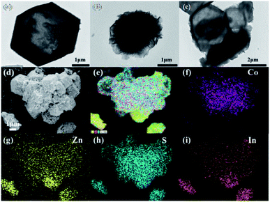 | ||
| Fig. 2 TEM images of Co3S4 (a), ZnIn2S4 (b) and ZC-5 (c) SEM images of ZC-5 (d and e) elemental mappings of Zn (f), S (g), Co (h) and In (i) in ZC-5. | ||
The BET specific surface area and porosity play important roles in evaluating the properties of prepared photocatalysts. The pore size distribution and nitrogen adsorption/desorption isotherm of ZnIn2S4 and ZC-5 samples are shown in Fig. S3.† It is evident that the two samples belong to mesoporous structure, owing to the IV adsorption isotherm with H3 hysteresis loop.40 The BET specific surface area of ZnIn2S4 and ZC-5 are 75.8 and 90.4 m2 g−1, respectively. Obviously, the specific surface area of ZC-5 increases after the introduction of Co3S4. Meanwhile, the pore size of samples is mainly focus on 2.5–7.5 nm based on the Barrett–Joyner–Halenda (BJH) pore size distribution curves (the inset in Fig. S3†), which coincides with the conclusion of mesoporous structure obtained by isotherm curve.41 Therefore, relatively large specific surface area and mesoporous structure can increase the reactive sites, which is beneficial to promote the photocatalytic hydrogen production.
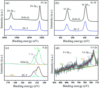
The XPS measurements were introduced to further confirm the elemental composition and valence state of pure ZnIn2S4 and ZC-5. Meanwhile, the electron transfer mechanism supported heterojunction formation in ZC-5 can be explained by the comparison of XPS between our photocatalyst and pure counterpart. As shown in Fig. S4,† the survey XPS spectrum proves the existence of Zn, In, C and S in ZnIn2S4 and ZC-5, it is worth noting that C element comes from conductive resin. Fig. 3a shows the XPS spectrum of Zn 2p, including two prominent peaks at 1021.51 and 1044.57 eV, which correspond exactly to Zn 2p3/2 and Zn 2p1/2 in the ZnIn2S4, respectively.42 However, the corresponding characteristic peaks of the Zn 2p in ZC-5 positive shifting is 1021.93 and 1044.98 eV. As displayed in Fig. 3b, the spectrum of In 3d in ZnIn2S4 shows two characteristic peaks at 444.61 and 452.18 eV which are assigned to In 3d5/2 and In 3d3/2, respectively.42 The offset direction is similar to the above, with the peaks position of In 3d in ZC-5 located at 444.80 and 452.34 eV, respectively. For the S 2p (Fig. 3c), the XPS spectrum of ZnIn2S4 can be deconvoluted into two prominent peaks which situates at 161.51 and 162.75 eV, corresponding to the S 2p3/2 and S 2p1/2, respectively.42 However, the peaks of S 2p in ZC-5 locate in the 161.60 and 162.84 eV. In addition, ZC-5 spectrum has one more characteristic peak at 169.09 eV compared with that of ZnIn2S4, which belongs to the vibration satellite peak existing in Co3S4.43 It can be seen that the valence states of Zn, In and S are +2, +3 and −2, respectively. Meanwhile, the Co 2p XPS spectrum (Fig. 3d) contains two spin–orbit doublets peaks which are Co 2p3/2 and Co 2p1/2 and two satellites peaks. The fitting peaks at 777.51 and 792.15 eV are ascribed to Co3+, and the peaks of Co2+ are located at 781.38 and 796.33 eV, as well as the vibration satellite peaks at 784.84 and 802.73 eV.45 It proves that Co3S4 exists in ZnIn2S4. Meanwhile, compared with those of pure ZnIn2S4, the peak positions of Zn 2p, In 3d and S 2p in the ZC-5 sample positive shifting specifies the transfer of electrons from the ZnIn2S4 with a rich electron system to the Co3S4 with a poor electron system. The electron density of the ZnIn2S4 in the ZC-5 composite decreases, resulting in higher binding energy. Meanwhile, because of the electronegativity of Zn (1.65) and In (1.78) are lower than that of Co (1.88), which is further proved that the electron of ZnIn2S4 tends to transfer to more electronegative Co3S4. Therefore, ZnIn2S4 and Co3S4 are not simply physically mixed. From the above analysis, it can be proved the formation of heterogeneous structures with strong electronic interaction between ZnIn2S4 and Co3S4 in ZC-5.44
3.2. Light absorption properties
Fig. 4a shows the UV-vis diffuse reflection spectra (DRS) of ZnIn2S4, ZC-X (X = 2, 5, 10, 20) and Co3S4. As can be seen, the absorption edge of ZnIn2S4 is ca. 540 nm. In contrast, Co3S4 exhibits broad absorption in the range of 200–800 nm. Owing to the coupling of Co3S4, the visible light absorption of the ZC-X composites is significantly enhanced, meanwhile the absorption range also gradually widens with the increase of Co3S4 ratio. In accordance with the Tauc plot equation,46 the band gap values of the prepared ZnIn2S4, ZC-X (X = 2, 5, 10, 20) and Co3S4 could be calculated as 2.55, 2.52, 2.51, 2.47, 2.46 and 1.62 eV, respectively (Fig. 4b), which proves that the band gap becomes narrow gradually with the increase of Co3S4 content in the composites. Therefore, the broader absorption range in the visible region arising from the coupling of Co3S4 play an important role in improving the photocatalytic performance of ZnIn2S4.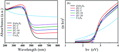 | ||
| Fig. 4 UV-vis DRS of ZnIn2S4, Co3S4 and ZC-X composite photocatalysts (a) the plots to determine the band gaps for each sample (b). | ||
Ultraviolet photoelectron spectroscopy (UPS) is employed to determine the valence band energy (EVB) of ZnIn2S4 ZC-5 and Co3S4, which are found to be 5.82, 6.03 and 5.1 eV via subtracting the width of the He I UPS spectra (Fig. S5†) from the excitation energy (21.2 eV). The valence band energy is subtracted from the band gap energy (Eg) to obtain the conduction band energy (ECB), which are calculated to be 3.27, 3.52 and 3.48 eV, respectively. On the basis of the reference standard in which 0 V vs. RHE (reversible hydrogen electrode) equals −4.44 eV vs. evac (vacuum level), the EVB, Eg and ECB values of ZnIn2S4, ZC-5 and Co3S4 in electron volts can be changed into electrochemical energy potentials in volts.47 Therefore, the valence band (VB) edge of ZnIn2S4 and ZC-5 can be observed at 1.38 and 1.59 V and that of Co3S4 is to be 0.66 V, the conduction band (CB) edge of ZnIn2S4, ZC-5 and Co3S4 are estimated to be −1.17, −0.92 and −0.96 V, respectively.
3.3. Charge-separation properties
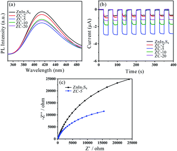
Generally, photoluminescence (PL) spectrum is measured to provide information which is in connection with charge generation, transfer and recombination. The weaker emission peak means a lower electron–hole recombination rate. The PL spectrum of prepared ZnIn2S4 and ZC-X are shown in Fig. 5a. Compared with all prepared samples, the fluorescence emission intensity of ZC-5 is the lowest, which implies that the recombination of photogenerated electrons and holes is effectively inhibited on account of electron transfer between ZnIn2S4 and Co3S4, so as to improve photocatalytic activity. Furthermore, the photocurrent response and electrochemical impedance spectroscopy (EIS) are carried out to explain the separation and recombination of electron–hole pair and electron transfer by using pure ZnIn2S4 and ZC-X as the electrode, respectively. As displayed in Fig. 5b, ZnIn2S4 and ZC-X photoelectrodes show the relatively stable current response and the trend are consistent with the literature12 under both dark and light conditions, but the saturation density of photocurrent is obviously different. It is clear that ZC-5 exhibits the highest photocurrent density when exposed to simulated sunlight, which is ca. 6.6 times of ZnIn2S4, suggesting that the photogenerated charges separation and transfer can be effectively promoted by combining with a certain amount of Co3S4, thus enhancing the photocatalytic hydrogen production effect. In addition, the electrochemical impedance spectroscopy (EIS) of prepared ZnIn2S4 and ZC-5 are depicted in Fig. 5c. Compared with ZnIn2S4, ZC-5 has a smaller radius, indicating that the electron transfer resistance of ZC-5 is lower, thus accelerating the electron transfer and inhibiting the charge recombination. Meanwhile, according to the photoluminescence spectrum, photocurrent response and electrochemical impedance spectroscopy of Co3S4 shown in Fig. S6,† the recombination rate of charge carriers on Co3S4 is relatively lower than ZnIn2S4. Consequently, the advantage of ZC-5 in preferably facilitating the effective separation of electron–hole pairs could improve photocatalytic activity.In addition, Mott–Schottky measurements are employed to ensure the conduction band (CB) boundary of the synthesized photocatalysts. As displayed in Fig. S7a and b,† the slopes of the tangent line in the Mott–Schottky diagram are positive, implying that the pure ZnIn2S4 and ZC-5 belong to the n-type semiconductor.48 At the same time, the flat-band potentials obtained by the x-axis intercepts can be approximated as the ECB potentials.49 It can be seen that the ECB potential of ZC-5 is estimated to be −0.94 V vs. NHE and that of ZnIn2S4 is about −1.20 V vs. NHE, and Fig. S7c† displays the ECB potential of Co3S4 which is estimated to be −0.93 V vs. NHE. All the results are almost consistent with the result of XPS valence band spectrum. The positive shift of ZC-5's ECB potential may be due to the change of fermi energy level caused by the interaction between ZnIn2S4 and Co3S4.22
3.4. Photocatalytic performance and stability
The photocatalytic hydrogen production of prepared ZnIn2S4, ZC-X (X = 2, 5, 10, 20) and Co3S4 are tested by the irradiation of simulated sunlight. As can be seen from Fig. 6a, the hydrogen production of ZnIn2S4 and ZC-X increase steadily over time. However, the hydrogen production of pure Co3S4 is difficult to be detected, which means that Co3S4 is inactive in photocatalytic hydrogen production. Meanwhile, as shown in Fig. 6b, when pure ZnIn2S4 is used as the photocatalyst, the production of hydrogen is merely 890 μmol g−1 h−1, possibly due to the quenching of photogenerated charge carriers. In the presence of Co3S4, ZC-X composites show better photocatalytic activity. When the compound amount of Co3S4 increases to 5%, the hydrogen production rate reaches a maximum of 4261 μmol g−1 h−1 which is nearly 4.8 times than that of original ZnIn2S4. However, as the proportion of Co3S4 continues to increase, the photocatalytic activity of hydrogen evolution tends to decrease, which may be caused by excess Co3S4 blocking ZnIn2S4's absorption of light.23,50 In order to evaluate the stability of the photocatalyst, a cycle test was conducted. Obviously, after three cycles, there is no significant change in the amount of photocatalytic hydrogen produced by ZC-5 (Fig. S8a†). Meanwhile, the XRD patterns of ZC-5 is consistent before and after photocatalytic reactions (Fig. S8b†), suggesting that the crystal structure of ZC-5 shows no significant change. Therefore, ZC-5 composite has excellent reusability and photostability in hydrogen production as a photocatalyst.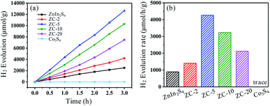 | ||
| Fig. 6 The photocatalytic H2 evolution performance over the synthesized ZnIn2S4 and ZC-X composites (a) the photocatalytic H2 evolution rate of prepared ZnIn2S4 and ZC-X composite photocatalysts (b). | ||
4. Photocatalytic mechanism
According to the band gap and the position of the CB and VB of ZnIn2S4 and Co3S4, the possible photocatalytic hydrogen production reaction mechanism of ZnIn2S4@Co3S4 nanocomposites is proposed and exhibited in Fig. 7. ZnIn2S4 nanoparticles can be excited to produce photogenerated electrons and holes when exposed to simulated sunlight. Compared with other composites, the lower photocatalytic activity of pure ZnIn2S4 is due to the higher recombination rate of the generated electrons and holes. However, when Co3S4 and ZnIn2S4 are combined, the excited electrons are quickly transferred from the CB of ZnIn2S4 to that of Co3S4 because of the relatively lower CB position of ZnIn2S4. Therefore, the photogenerated electron–hole pairs recombination of ZnIn2S4 can be effectively inhibited. Since the ECB potential of ZnIn2S4@Co3S4 is lower than the reduction potential of H+/H2, the photogenerated electrons accumulated on Co3S4 convert H+ in the water to H2 in a reduction reaction. Meanwhile, the photogenerated holes quickly transferred from the VB of ZnIn2S4 to that of Co3S4 on account of the EVB potential of ZnIn2S4 is more positive than that of Co3S4. Moreover, the oxidation reactions will be further occurred, which react between sacrificial agents (TEOA) and the holes. Consequently, heterogeneous structures may be formed at the interface between ZnIn2S4 and Co3S4, which promote electron transfer and inhibit electron–hole pairs recombination, thus improving the photocatalytic hydrogen production activity of composites.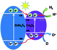 | ||
| Fig. 7 Schematic illustration of the possible mechanism for photocatalytic hydrogen evolution over the ZnIn2S4@Co3S4 composite photocatalyst. | ||
5. Conclusions
In summary, a series of ZnIn2S4@Co3S4 composite photocatalysts with certain structure are successfully carried out in photocatalytic hydrogen production under simulated sunlight. The three-dimensional Co3S4 samples are firstly obtained via solvothermal process and quenching of ZIF-67, then the coupling of obtained Co3S4 and ZnIn2S4 is achieved through a simple hydrothermal reaction. It is revealed that the ZnIn2S4@Co3S4 composite materials show better photocatalytic hydrogen production performance than pure ZnIn2S4, and the coupling amount of Co3S4 has a profound effect on the photocatalytic activity. From all synthesized samples, the ZC-5 composite possesses superior photocatalytic property with the hydrogen evolution rate of 4261 μmol g−1 h−1 which is approximately 4.8 times than that of pure ZnIn2S4 (890 μmol g−1 h−1). The enhanced photocatalytic activity of ZC-5 may be attributed to the formation of heterostructure which promotes electron transfer and inhibits electron–hole pairs recombination, and the more active sites provided by the increased specific surface area. In addition, ZC-5 photocatalyst exhibits remarkable stability in photocatalytic hydrogen production performance. The working mechanism of ZnIn2S4@Co3S4 heterojunction is discussed in detail, which provides reference for the potential application of photocatalytic hydrogen production technology in the field of energy.Conflicts of interest
There are no conflicts to declare.Acknowledgements
The authors of this work gratefully appreciate the financial support provided by National Natural Science Foundation of China (No. 41573096, 21707064), Program for Changjiang Scholars and Innovative Research Team in University (No. IRT_17R71), Program for Professor of Special Appointment (Eastern Scholar) at Shanghai Institutions of Higher Learning (QD2019005).Notes and references
- Y. Li, Z. Jin, L. Zhang and K. Fan, Chin. J. Catal., 2019, 40, 390–402 CrossRef CAS.
- T. Huang, W. Chen, T.-Y. Liu, Q.-L. Hao and X.-H. Liu, Int. J. Hydrogen Energy, 2017, 42, 12254–12261 CrossRef CAS.
- A. Kudo and Y. Miseki, Chem. Soc. Rev., 2009, 38, 253–278 RSC.
- G. Colón, Appl. Catal., A, 2016, 518, 48–59 CrossRef.
- A. Fujishima and K. Honda, Nature, 1972, 238, 37–38 CrossRef CAS.
- X. Chen, S. Shen, L. Guo and S. S. Mao, Chem. Rev., 2010, 110, 6503–6570 CrossRef CAS.
- J. Huo, L. Fang, Y. Lei, G. Zeng and H. Zeng, J. Mater. Chem. A, 2014, 2, 11040–11044 RSC.
- S. Yang, Y. Gong, J. Zhang, L. Zhan, L. Ma, Z. Fang, R. Vajtai, X. Wang and P. M. Ajayan, Adv. Mater., 2013, 25, 2452–2456 CrossRef CAS.
- Y. Wu, H. Wang, W. Tu, S. Wu, Y. Liu, Y. Z. Tan, H. Luo, X. Yuan and J. W. Chew, Appl. Catal., B, 2018, 229, 181–191 CrossRef CAS.
- H. Tian, M. Liu and W. Zheng, Appl. Catal., B, 2018, 225, 468–476 CrossRef CAS.
- Y. Pan, X. Yuan, L. Jiang, H. Yu, J. Zhang, H. Wang, R. Guan and G. Zeng, Chem. Eng. J., 2018, 354, 407–431 CrossRef CAS.
- A. Yan, X. Shi, F. Huang, M. Fujitsuka and T. Majima, Appl. Catal., B, 2019, 250, 163–170 CrossRef CAS.
- S. Wang, B. Y. Guan and X. W. D. Lou, J. Am. Chem. Soc., 2018, 140, 5037–5040 CrossRef CAS.
- Z. Chen, D. Li, W. Zhang, Y. Shao, T. Chen, M. Sun and X. Fu, J. Phys. Chem. C, 2009, 113, 4433–4440 CrossRef CAS.
- Z. Lei, W. You, M. Liu, G. Zhou, T. Takata, M. Hara, K. Domen and C. Li, Chem. Commun., 2003, 2142–2143, 10.1039/b306813g.
- X. Peng, L. Ye, Y. Ding, L. Yi, C. Zhang and Z. Wen, Appl. Catal., B, 2020, 260, 118152 CrossRef CAS.
- X. Bai and J. Li, Mater. Res. Bull., 2011, 46, 1028–1034 CrossRef CAS.
- S. Shen, L. Zhao, Z. Zhou and L. Guo, J. Phys. Chem. C, 2008, 112, 16148–16155 CrossRef CAS.
- C. Du, B. Yan, Z. Lin and G. Yang, J. Mater. Chem. A, 2020, 8, 207–217 RSC.
- S. Shen, L. Zhao, X. Guan and L. Guo, J. Phys. Chem. Solids, 2012, 73, 79–83 CrossRef CAS.
- H. An, Z. Lv, K. Zhang, C. Deng, H. Wang, Z. Xu, M. Wang and Z. Yin, Appl. Surf. Sci., 2021, 536, 147934 CrossRef CAS.
- J. Zhou, D. Chen, L. Bai, L. Qin, X. Sun and Y. Huang, Int. J. Hydrogen Energy, 2018, 43, 18261–18269 CrossRef CAS.
- L. Wei, Y. Chen, Y. Lin, H. Wu, R. Yuan and Z. Li, Appl. Catal., B, 2014, 144, 521–527 CrossRef CAS.
- M. Zhang, J. Yao, M. Arif, B. Qiu, H. Yin, X. Liu and S.-m. Chen, Appl. Surf. Sci., 2020, 526, 145749 CrossRef CAS.
- H. Song, N. Wang, H. Meng, Y. Han, J. Wu, J. Xu, Y. Xu, X. Zhang and T. Sun, Dalton Trans., 2020, 49, 10816–10823 RSC.
- S. Shen, L. Zhao and L. Guo, J. Phys. Chem. Solids, 2008, 69, 2426–2432 CrossRef CAS.
- H. Liu, C. Xu, D. Li and H.-L. Jiang, Angew. Chem., Int. Ed., 2018, 130, 5477–5481 CrossRef.
- G. Huang, Q. Yang, Q. Xu, S.-H. Yu and H.-L. Jiang, Angew. Chem., Int. Ed., 2016, 128, 7505–7509 CrossRef.
- Y. Liu, W. Miao, X. Fang, Y. Tang, D. Wu and S. Mao, Chem. Eng. J., 2020, 380, 122584 CrossRef CAS.
- M. Wang, Z. Shen, X. Zhao, F. Duanmu, H. Yu and H. Ji, J. Hazard. Mater., 2019, 371, 352–361 CrossRef CAS.
- H. Xu, J. Cao, C. Shan, B. Wang, P. Xi, W. Liu and Y. Tang, Angew. Chem., Int. Ed. Engl., 2018, 57, 8654–8658 CrossRef CAS.
- D. P. Kumar, H. Park, E. H. Kim, S. Hong, M. Gopannagari, D. A. Reddy and T. K. Kim, Appl. Catal., B, 2018, 224, 230–238 CrossRef CAS.
- N. Li, H. Huang, R. Bibi, Q. Shen, R. Ngulube, J. Zhou and M. Liu, Appl. Surf. Sci., 2019, 476, 378–386 CrossRef CAS.
- J.-T. Ren, K. Yuan, K. Wu, L. Zhou and Y.-W. Zhang, Inorg. Chem. Front., 2019, 6, 366–375 RSC.
- S. Bala, I. Mondal, A. Goswami, U. Pal and R. Mondal, J. Mater. Chem. A, 2015, 3, 20288–20296 RSC.
- Z. F. Huang, J. Song, K. Li, M. Tahir, Y. T. Wang, L. Pan, L. Wang, X. Zhang and J. J. Zou, J. Am. Chem. Soc., 2016, 138, 1359–1365 CrossRef CAS.
- L. Xu, W.-q. Chen, S.-q. Ke, S.-m. Zhang, M. Zhu, Y. Zhang, W.-y. Shi, S. Horike and L. Tang, Chem. Eng. J., 2020, 382, 122810 CrossRef CAS.
- B. Liu, X. Liu, J. Liu, C. Feng, Z. Li, C. Li, Y. Gong, L. Pan, S. Xu and C. Q. Sun, Appl. Catal., B, 2018, 226, 234–241 CrossRef CAS.
- F. Luo, D. Ma, Y. Li, H. Mi, P. Zhang and S. Luo, Electrochim. Acta, 2019, 299, 173–181 CrossRef CAS.
- S. G. Mohamed, I. Hussain and J. J. Shim, Nanoscale, 2018, 10, 6620–6628 RSC.
- M. Thommes, K. Kaneko, A. V. Neimark, J. P. Olivier, F. Rodriguez-Reinoso, J. Rouquerol and K. S. W. Sing, Pure Appl. Chem., 2015, 87, 1051–1069 CAS.
- X.-l. Li, X.-j. Wang, J.-y. Zhu, Y.-p. Li, J. Zhao and F.-t. Li, Chem. Eng. J., 2018, 353, 15–24 CrossRef CAS.
- Y. Guo, J. Tang, H. Qian, Z. Wang and Y. Yamauchi, Chem. Mater., 2017, 29, 5566–5573 CrossRef CAS.
- L. Ye, J. Fu, Z. Xu, R. Yuan and Z. Li, ACS Appl. Mater. Interfaces, 2014, 6, 3483–3490 CrossRef CAS.
- S. Hou, Y. Lian, Y. Bai, Q. Zhou, C. Ban, Z. Wang, J. Zhao and H. Zhang, Electrochim. Acta, 2020, 341, 136053 CrossRef CAS.
- J. Tauc, R. Grigorovici and A. Vancu, Phys. Status Solidi B, 1966, 15, 627–637 CrossRef CAS.
- J. Liu, Y. Liu, N. Liu, Y. Han, X. Zhang, H. Huang, Y. Lifshitz, S.-T. Lee, J. Zhong and Z. Kang, Science, 2015, 347, 970–974 CrossRef CAS.
- A. Wolcott, W. A. Smith, T. R. Kuykendall, Y. Zhao and J. Z. Zhang, Adv. Funct. Mater., 2009, 19, 1849–1856 CrossRef CAS.
- Y. Xia, Q. Li, K. Lv, D. Tang and M. Li, Appl. Catal., B, 2017, 206, 344–352 CrossRef CAS.
- L. Bai, X. Cai, J. Lu, L. Li, S. Zhong, L. Wu, P. Gong, J. Chen and S. Bai, ChemCatChem, 2018, 10, 2107–2114 CrossRef CAS.
Footnote |
| † Electronic supplementary information (ESI) available. See DOI: 10.1039/d0ra10799a |
| This journal is © The Royal Society of Chemistry 2021 |


