
 Open Access Article
 This Open Access Article is licensed under a Creative Commons Attribution-Non Commercial 3.0 Unported Licence
Self-supporting V2O5 nanofiber-based electrodes for magnesium–lithium-ion hybrid batteries†
Achim M. Diem,
Kevin Hildenbrand,
Leila Raafat,
Joachim Bill and
Zaklina Burghard *
*
Institute for Materials Science, University of Stuttgart, Stuttgart, Germany. E-mail: zaklina.burghard@imw.uni-stuttgart.de
First published on 5th January 2021
Abstract
The increasing demand for high energy, sustainable and safer rechargeable electrochemical storage systems for portable devices and electric vehicles can be satisfied by the use of hybrid batteries. Hybrid batteries, such as magnesium–lithium-ion batteries (MLIBs), using a dual-salt electrolyte take advantage of both the fast Li+ intercalation kinetics of lithium-ion batteries (LIBs) and the dendrite-free anode reactions. Here we report the utilization of a binder-free and self-supporting V2O5 nanofiber-based cathode for MLIBs. The V2O5 cathode has a high operating voltage of ∼1.5 V vs. Mg/Mg2+ and achieves storage capacities of up to 386 mA h g−1, accompanied by an energy density of 280 W h kg−1. Additionally, a good cycling stability at 200 mA g−1 over 500 cycles is reached. The structural integrity of the V2O5 cathode is preserved upon cycling. This work demonstrates the suitability of the V2O5 cathode for MLIBs to overcome the limitations of LIBs and MIBs and to meet the future demands of advanced electrochemical storage systems.
1 Introduction
The increasing demand of electrochemical storage systems for various portable devices and electric vehicles is accelerating the development of batteries, especially lithium-ion batteries (LIBs).1,2 The electrochemical performance of LIBs is so far incomparable due to their high energy density, fast Li+ insertion kinetics, rate capability and long-term stability.2,3 However, lithium is a highly reactive metal, has restricted natural resources, and safety hazards. In particular, the thermal runaway caused by dendrite formation on the anode side limits the application of LIBs. These drawbacks encouraged the research of alternative mono- and multivalent metal-ion battery systems.4–6 Among them, magnesium-ion batteries (MIBs) are very promising, as magnesium is more abundant and its theoretical volumetric capacity of 3832 mA h cm−3 is roughly twice as that of lithium.5 Furthermore, magnesium anodes do not form dendrites which improves the safety of the entire electrochemical storage system. However, the sluggish Mg2+ solid state diffusion within most cathode materials, restricting the storage capacity and rate capability of MIBs, has to be overcome.7 Accordingly, suitable cathode materials, which can host Mg2+, still have to be developed and optimized. Another important issue is utilizing a non-corrosive and stable electrolyte, which does not form blocking layers, as it is the case for conventional perchlorates in organic solvents.4To overcome the drawbacks of LIBs and MIBs and simultaneously exploit their advantages, the hybrid magnesium–lithium-ion battery (MLIB) is a favorable candidate. A lithium-intercalation cathode and magnesium anode are thereby used, in combination with a dual-salt electrolyte, containing both Mg2+ and Li+.5 This approach utilizes the fast Li+ insertion kinetics into the cathode and therefore, high storage capacities and high rate capabilities can be reached. Furthermore, on the anode side Mg2+ is stripped and deposited without dendrite formation during the electrochemical cycling.8,9 Specifically, during the charge process, Li+ is de-intercalated from the cathode and Mg2+ is deposited on the Mg anode, whereas during the discharge process the reactions are vice versa (Fig. 1a).
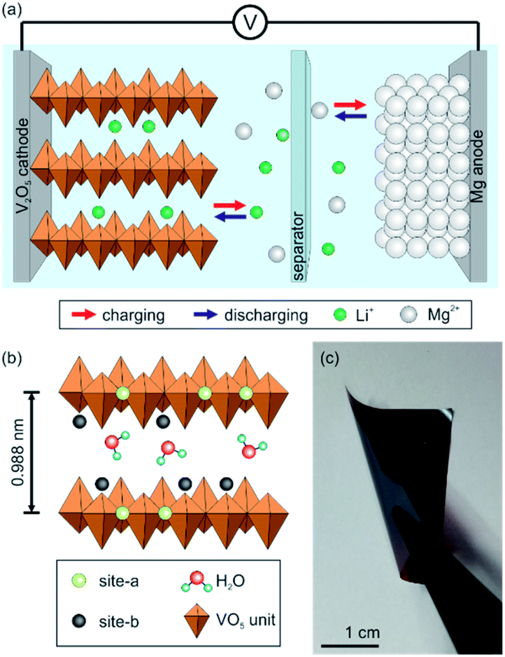 | ||
| Fig. 1 (a) Schematic depiction of the design and working principle of hybrid batteries using a dual-salt electrolyte and Mg anode. The working principle includes the de-intercalation of Li+ from the cathode and the deposition of Mg2+ on the Mg anode during charging. For the discharging process the reactions are vice versa. (b) Scheme of the V2O5 bilayer with its intercalation sites, site-a and site-b, the incorporated water molecules assuring that the interlayer distance is large enough to enable ion intercalation. (c) Digital image showing the high flexibility of the self-supporting V2O5 nanofiber-based cathode. | ||
The concept of MLIBs and therefore their development is still in its early stages. Hence, only a limited number of cathode materials are investigated. These include Mo6S8,9 dichalcogenides,10–14 phosphates15 and metal oxides.16–21 Although the working principle and intercalation mechanisms of these cathode materials has been proven, some of them lag behind in working voltage and energy density. Therefore, the development of MLIBs requires further research in respect to high voltage cathode materials delivering high energy densities.
A promising intercalation compound for a variety of mono- and multivalent ions is vanadium pentoxide (V2O5) with its rich redox chemistry promoting high storage capacities and energy densities. V2O5 nanofibers are suitable as cathode material for MLIBs as they comprise a spacious bilayer of chain-like VO5 units (Fig. 1b). The space between them contains water molecules, which keep the distance large enough to host intercalating ions and facilitate their insertion.22,23 Additionally, the chain-like bilayer provides two different intercalation sites (site-a and site-b, Fig. 1b). Specifically, site-a is near the planar oxygen atom, whereas site-b is around the apical oxygen atoms of the VO5 units.24 Furthermore, the nanofibers can be self-assembled into binder-free and self-supporting paper-like thin films having a uniform layered sheet-like structure providing a high mechanical flexibility. Such electrodes can be beneficial for the overall cell performance, as parasitic side reactions found in conventional slurry-based electrodes are prevented.
Herein, we report the usage of a binder-free and self-supporting V2O5 nanofiber-based cathode for MLIBs. The V2O5 cathode is fabricated by a self-assembly approach, following a reported procedure.25,25,26 The commonly all phenyl complex (APC) electrolyte for MLIBs was used in this work as it has proven its stability over the required electrochemical potential window. The APC electrolyte was prepared by dissolving aluminum chloride (AlCl3) in tetrahydrofuran (THF), followed by the addition of a phenyl magnesium chloride solution in THF. An appropriate amount of LiCl is added, leading to 0.25 M APC and 1 M LiCl.27 The V2O5 cathode was assembled in an argon-filled glovebox in Swagelok-type cells with Mo as current collectors, as stainless steel is instable in the APC electrolyte (ESI, Fig. S1†). Mg metal is used as anode, since lithium metal reacts within the electrolyte (ESI, Fig. S2†). Glass fiber and polypropylene membranes were employed as the separator.
2 Experimental section
2.1. Synthesis of the V2O5 nanofibers
The V2O5 nanofiber dispersion was prepared by adding 1 g ammonium–vanadate (Fluka) and 10 g of Dowex50W8 50-100 (Alfa Aesar) as acidic ion exchanger to 200 ml deionized water. The mixture was heated for 10 min at 80 °C in an oil bath and is subsequently slowly cooled down to room temperature and aged for six weeks.2.2. Electrode fabrication
The obtained V2O5 nanofiber dispersion was diluted with deionized water (1![[thin space (1/6-em)]](https://www.rsc.org/images/entities/char_2009.gif) :1), from which 9 ml were poured into a glass beaker on a freshly cleaned Si(100) p-type wafer (Wacker, Sitronic). After complete evaporation of the water, the V2O5 film could be detached from the Si wafer in a water bath to obtain the self-supporting thin film. The latter was further treated in a two-step procedure, utilizing a climatic chamber (VC7018, Vötsch). The first step included a temperature and relative humidity increase within 15 minutes to 40 °C and 80%, respectively. This temperature was fixed for 15.5 hours, whereas the humidity was only held for 1 hour, followed by its decrease to 20% within 10 hours and kept for 4.5 hours. In the second annealing step the temperature was increased from 25 °C to 150 °C over 30 minutes and kept for two hours, followed by a temperature reduction to room temperature. The annealed self-supporting films were coated from both sides with ∼10 nm carbon (SCD 040, Balzers Union).
:1), from which 9 ml were poured into a glass beaker on a freshly cleaned Si(100) p-type wafer (Wacker, Sitronic). After complete evaporation of the water, the V2O5 film could be detached from the Si wafer in a water bath to obtain the self-supporting thin film. The latter was further treated in a two-step procedure, utilizing a climatic chamber (VC7018, Vötsch). The first step included a temperature and relative humidity increase within 15 minutes to 40 °C and 80%, respectively. This temperature was fixed for 15.5 hours, whereas the humidity was only held for 1 hour, followed by its decrease to 20% within 10 hours and kept for 4.5 hours. In the second annealing step the temperature was increased from 25 °C to 150 °C over 30 minutes and kept for two hours, followed by a temperature reduction to room temperature. The annealed self-supporting films were coated from both sides with ∼10 nm carbon (SCD 040, Balzers Union).
2.3. Electrolyte preparation
The synthesis of the APC electrolyte was performed in an argon filled glovebox (<1 ppm oxygen and water) following a procedure previously reported by Mizrahi and coworkers.1 3.33 g anhydrous aluminum chloride (AlCl3, 99.99%, Sigma Aldrich) were slowly added and dissolved in 75 ml tetrahydrofuran (THF) under vigorous stirring for 12 hours. 25 ml of the phenyl magnesium chloride solution (2 M in THF, Sigma Aldrich) were then added and the solution was stirred for 12 hours. Finally, 1 M anhydrous lithium chloride (LiCl, 99%, Alfa Aesar) was added to the 0.25 M APC solution, followed by stirring for 12 hours.2.4. Cell assembly
Swagelok-type cells made of polytetrafluoroethylene (PTFE) were assembled in an argon filled glovebox (<1 ppm oxygen and water), using molybdenum current collectors. A polypropylene membrane and a glass fiber membrane (Grade 934-AH, Whatman), each with a diameter of 10.5 mm, were added atop the V2O5 cathode (8 mm diameter), followed by the addition of the APC-based electrolyte. Freshly polished Mg discs with a diameter of 10 mm were used for the stability tests and impedance measurements. For all other electrochemical measurements, a Mg disc with a diameter of 8 was used as anode.2.5. Characterization methods
The microstructure and structure of the V2O5 cathodes were characterized by scanning electron microscopy (SEM, Zeiss Ultra 55) and X-ray diffraction (PXRD, Rigaku Smartlab). For the latter, copper Kα radiation, an acceleration voltage of 40 kV and current of 30 mA in grazing incident mode with a 0.02° step size in the range of 5–15° were used. Fourier-transform infrared spectroscopy (FTIR, Tensor II, Bruker) was performed in the range of 400–1200 cm−1.2.6. Electrochemical measurements
To determine the stability of the current collectors, linear sweep voltammetry (LSV) was carried out at 1 mV s−1 in the voltage range of 0.02–3.0 V. The determination of the ionic conductivity included electrochemical impedance spectroscopy (EIS) in the frequency range of 1 MHz to 100 mHz. The Mg deposition and dissolution was investigated by means of cyclic voltammetry (CV) at 5 mV s−1 in the range of −1.0 to 3.0 V. CV scans to determine the cathode's performance and intercalation potentials was performed at 0.05, 0.1, 0.2, 0.5 and 1.0 mV s−1 in the potential window of 0.25–3.0 V. Galvanostatic charge and discharge experiments were carried out within the voltage window of 0.25–3.0 V at the current densities of 10, 100, 200, 500 mA g−1. All electrochemical measurements were performed on an electrochemical test station (VSP300, Biologic) under ambient conditions. The ionic conductivity σ is calculated using σ = thickness of separators/(resistance × electrode area), where the resistance was determined by the high frequency response of the impedance measurement, using the Bode plot.3 Results and discussion
In general, addition of LiCl to the APC electrolyte provides Li+ for intercalation as well as, significantly improves its ionic conductivity.5 In order to determine the latter, electrochemical impedance spectroscopy (EIS) was performed (ESI, Fig. S3†). The significant influence of the LiCl addition is however not observed. The determined ionic conductivity for both electrolytes is similar (∼1.14 mS cm−1) and lower than that reported for the APC electrolyte.27 We attribute this reduced ionic conductivity to the additionally used polypropylene membrane with its small pores and high density, which was beneficial for the V2O5 cathode's stability during electrochemical testing. Nevertheless, the ionic conductivity was sufficient to promote the intercalation of Li+. Furthermore, the reversible stripping and deposition of Mg2+ on the Mg anode side is fulfilled by both electrolytes (ESI, Fig. S4†).The comparison of the CV scans using the self-supporting V2O5 cathode and both electrolytes (Fig. 2a) reveal that the electrochemical performance in the APC electrolyte is limited due to the sluggish intercalation, diffusion kinetics and high polarization effect of Mg2+.7 Notably, when using the APC + LiCl electrolyte, the electrochemical activity of the cathode is significantly enhanced by the fast intercalation kinetics of Li+. Hence, the V2O5 cathode shows distinct de-intercalation peaks during the anodic scan around 2.18 V. During the cathode reactions a clear intercalation peak at 1.41 V with a small shoulder around 2 V is observed. These intercalation potentials are similar to vanadium oxide-based cathodes,20,21 and comparable to other oxide-based cathode materials.17,19,28 The following simplified reactions for the V2O5 cathode occur during the discharge process:
| Anode: Mg → Mg2+ + 2e− | (1) |
| Cathode: V2O5 + Li+ + e− → LiV2O5 | (2) |
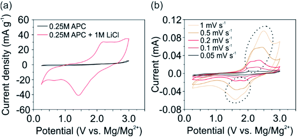 | ||
| Fig. 2 Comparison of the electrochemical performance of 2nd CV cycles of a V2O5 cathode at a scan rate of 0.1 mV s−1 (a) using the APC and APC + LiCl electrolyte and (b) CV scans at different scan rates ranging from 0.5 to 1 mV s−1, using the APC + LiCl electrolyte. | ||
By performing CV experiments at different scan rates (Fig. 2b), a noticeable splitting of the de-/intercalation peaks (marked by a circle in Fig. 2b) is observed at scan rates below 1 mV s−1. The occurrence of two distinct potentials refers to the intercalation at two different sites in the V2O5 host lattice. In particular, at higher potentials (∼1.9 V) ions are intercalated at site-a (Fig. 1b) near the center of the planar oxygen atoms. At lower potentials (∼1.6 V) intercalation at site-b around the apical oxygen atoms of the VO5 units take place.24 Furthermore, a small intercalation peak around 0.6 V can be noticed. This peak is more pronounced at lower scan rates and vanishes at higher scan rates. However, the complementary de-intercalation peak is not observed. Therefore, we conclude, that slow diffusing species, i.e. Mg2+ or Mg-based complexes, are irreversibly intercalated or adsorbed on the surface of the V2O5 nanofibers. As it is reported that Mg2+ can be intercalated but not de-intercalated,8,12,28,29 we assume that Mg2+ is the species which is irreversibly intercalated. To verify this, we analyzed the shift of the anodic peak current towards higher potentials with increasing the scan rate. This analysis enables the investigation of and distinction between the capacitive and diffusive contributions of the overall electrochemical performance. The current I can be expressed at any potential by
| I(V) = k1ν1/2 + k2ν, | (3) |
To further characterize the V2O5 cathode in terms of storage capacity, rate capability and cycling stability, galvanostatic charge and discharge experiments were conducted. Fig. 3a shows the determined specific discharge capacity of the cathode. In particular, a maximum discharge capacity of 386, 174, 93 and 4 mA h g−1 were obtained for 10, 100, 200 and 500 mA g−1, respectively. Stable discharge capacities for the first 20 cycles were observed for all investigated current densities except for 10 mA g−1. Notably, for the latter fast fading of the specific capacity was observed. This observation can be attributed the irreversible Mg2+ intercalation and its occupancy of the Li+ intercalation sites, as concluded from the CV measurements. Interestingly, at a current density of 200 mA g−1 (Fig. 3b) the storage capacity continuously increased over the first 70 cycles, from 33 mA h g−1 up to 48 mA h g−1. This increase can be ascribed to the formation of an interphase that supports the ion diffusion between the electrode and electrolyte leading to a more efficient de-/intercalation process. After 500 cycles the V2O5 cathode still delivers ∼20 mA h g−1. The accompanied Coulomb efficiency is almost 100% over all 500 cycles, showing the high reversibility of the electrochemical processes.
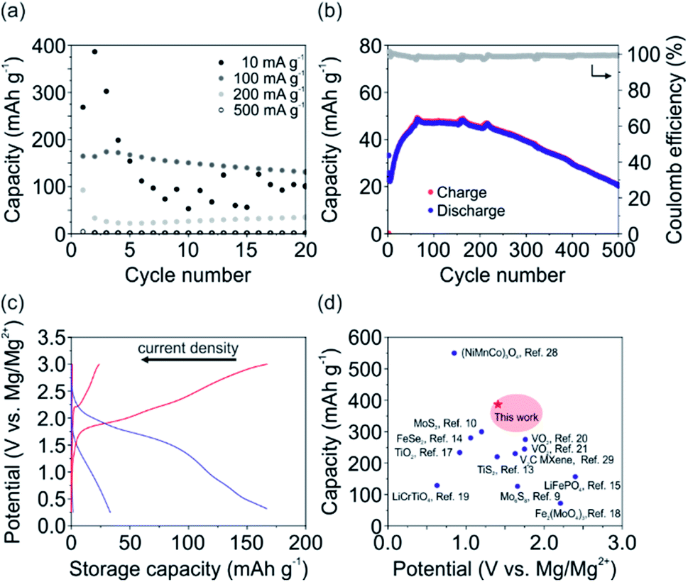 | ||
| Fig. 3 Galvanostatic charge and discharge experiments using the APC + LiCl electrolyte. (a) Determined discharge capacity of the V2O5 cathode in dependence of the applied current density. (b) Charge and discharge capacity, as well as the Coulomb efficiency over 500 cycles for the V2O5 at a current density of 200 mA g−1. (c) Voltage–capacity profiles (2nd cycle) for the current densities of 500, 200 and 100 mA g−1. (d) Comparison of the V2O5 cathode to other cathode materials, including oxides,8,17–21,28 sulfides,9,10,13 carbides,29 selenides14 and phosphates.15 | ||
The voltage–capacity profiles for the current densities of 100, 200, 500 mA g−1 are shown in Fig. 3c, with corresponding discharge capacities of 167, 33 and 1.5 mA g−1 and energy densities of 174, 25, 0.6 W h kg−1. For the current density of 10 mA g−1 the discharge capacity of the 2nd cycle is 386 mA h g−1 with an accompanied energy density of 280 W h kg−1. The profile corresponding to 100 mA g−1 shows two de-/intercalation plateaus, similar to the CV measurements for low scan rates (Fig. 2b). This further supports the assumption that Li+ occupy the two distinct intercalation sites of the V2O5 host lattice (Fig. 1b). Specifically, intercalation close to the center of the square-planar oxygen at higher potentials (∼1.9 V) and intercalation around the apical oxygen of the VO5 unit at lower potentials (∼1.5 V) are reported for the insertion of Li+.24
To validate the superior performance of our V2O5 cathode to reported MLIB cathode materials, the discharge capacity is plotted vs. the intercalation potential (Fig. 3d). The reported cathode materials include oxide-based materials,8,17–21,28 sulfides,9,10,13 carbides,29 selenides14 and phosphates.15 The comparison reveals that our V2O5 nanofiber-based cathode with its high storage capacity of 386 mA h g−1 is superior to almost all other reported cathode materials. Additionally, the high intercalation potentials of ∼1.4 V and ∼2 V vs. Mg/Mg2+ of our V2O5 cathode are comparable and even higher than other oxide-based cathode materials. The high intercalation potentials are important for achieving high energy densities, crucial in the development of rechargeable metal-ion batteries for portable devices and electric vehicles. Our V2O5 cathode with its binder-free and self-supporting design using V2O5 nanofibers, therefore renders the cathode as a promising candidate for MLIBs.
To investigate the cathode's structural stability during electrochemical processes, X-ray diffraction (XRD), Fourier-transform infrared spectroscopy (FTIR) and scanning electron microscopy (SEM) was performed for the pristine V2O5 cathode and after 150 cycles at a current density of 100 mA g−1. The XRD pattern (Fig. 4a) for both the pristine and the tested V2O5 cathode show the typical (001) reflection for bilayered monoclinic V2O5·nH2O (space group C2/m),25,31 revealing the preservation of the structural integrity of the cathode upon cycling. The shift of the reflection around 9° indicates the decrease of the interlayer distance, specifically from 0.988 nm for the pristine to 0.950 nm for the tested cathode. This reduction of the interlayer distance is attributed to the stronger interaction between the intercalated positive species and the negatively charged VO5 units.32 The FTIR measurements (Fig. 4b) verify the presence of the typical adsorption bands for V![[double bond, length as m-dash]](https://www.rsc.org/images/entities/char_e001.gif) O and V–O–V stretching at around 970 and 715 cm−1, respectively, and the 3 V–O stretching below 500 cm−1 found for V2O5.24 Specifically, the VO stretching of the tested cathode is more pronounced and shifted to lower wavenumbers. Contrary, the V–O–V stretching is weakened upon electrochemical cycling. These changes of bonding confirm the findings of the CV and charge/discharge experiments, that ions are mainly intercalated around the apical oxygen atoms of the VO5 units (site-b). In addition, the SEM cross-section images (Fig. 4c) before and after the electrochemical cycling show the uniform stacking of V2O5 sheets, which are formed during the self-assembly process.22,25 The SEM investigation further reveals no delamination of the film and no crack formation upon cycling. The preservation of the structural integrity of the V2O5 nanofiber-based cathode shows, that the cathode is able to host and accommodate ions and that the occurring stresses during intercalation are well distributed.
O and V–O–V stretching at around 970 and 715 cm−1, respectively, and the 3 V–O stretching below 500 cm−1 found for V2O5.24 Specifically, the VO stretching of the tested cathode is more pronounced and shifted to lower wavenumbers. Contrary, the V–O–V stretching is weakened upon electrochemical cycling. These changes of bonding confirm the findings of the CV and charge/discharge experiments, that ions are mainly intercalated around the apical oxygen atoms of the VO5 units (site-b). In addition, the SEM cross-section images (Fig. 4c) before and after the electrochemical cycling show the uniform stacking of V2O5 sheets, which are formed during the self-assembly process.22,25 The SEM investigation further reveals no delamination of the film and no crack formation upon cycling. The preservation of the structural integrity of the V2O5 nanofiber-based cathode shows, that the cathode is able to host and accommodate ions and that the occurring stresses during intercalation are well distributed.
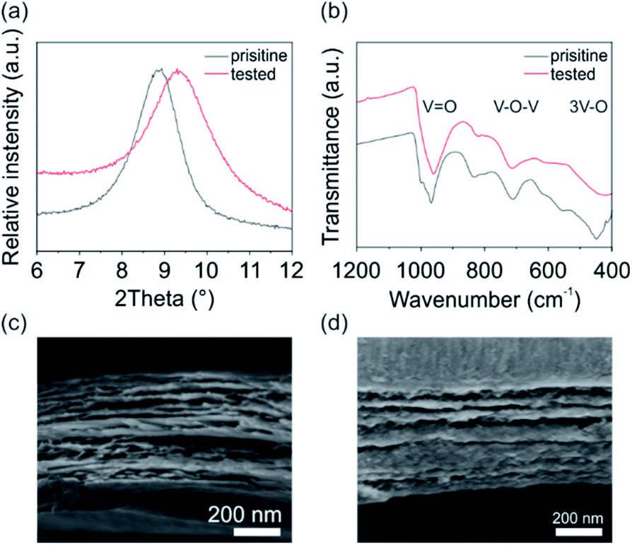 | ||
| Fig. 4 Investigation of the pristine and electrochemical tested V2O5 cathode by (a) XRD and (b) FTIR. SEM cross-section images of the (c) pristine and (d) tested cathode, showing the preservation of the structural integrity of the V2O5 cathode upon electrochemical cycling. | ||
4 Conclusion and outlook
In summary, we presented a proof-of-concept and the potential of the utilization of a binder-free and self-supporting V2O5 cathode in MLIBs. The V2O5 nanofiber-based cathode shows reversible Li+ intercalation at high potentials of ∼1.5 V and ∼2 V vs. Mg/Mg2+. Storage capacities of up to 386 mA h g−1 with an accompanied energy density of 280 W h kg−1 at a current density of 10 mA g−1 were thereby achieved. In addition, a good cycling stability at 200 mA g−1 over 500 cycles was observed. Notably, the structural integrity of the V2O5 self-supporting cathode was preserved upon electrochemical cycling. FTIR measurements confirmed ion intercalation specific sites of the V2O5 host lattice. In conclusion, this work shows the feasibility of implementing a V2O5 nanofiber-based cathode in MLIBs, enabling high storage capacities and high intercalation potentials. To this end, a major challenge, which still has to be addressed, is the improvement of the self-supporting and binder-free V2O5 cathode electrical conductivity. In this regard, a combination with mechanically flexible graphene or reduced graphene oxide sheets, or chemical doping of the V2O5 nanofibers could be considered as promising approaches.Author contributions
This manuscript was written with the contributions of all authors. All authors have read and agreed to the published version. Conceptualization, A. M. D. and Z. B.; methodology, A. M. D., K. H. and L. R.; validation, A. M. D., L. R. J.B. and Z. B.; investigation, A. M. D., K. H.; writing—original draft preparation, A. M. D.; writing—review and editing, A. M. D., L. R., J. B. and Z. B.; supervision, J. B. and Z. B.; project administration, Z. B.; funding acquisition, Z. B.Conflicts of interest
There are no conflicts to declare.Acknowledgements
The authors are thankful to the group of J. Spatz and M. Sitti from the Max Planck Institute in Stuttgart for equipment use and technical support. The authors greatly appreciate T. Wörner for engineering support and T. Jahnke for fruitful discussions. The financial support provided by the Vector Stiftung (project no. 0090018) is highly appreciated.Notes and references
- M. Armand and J.-M. Tarascon, Nature, 2008, 451, 652–657 CrossRef CAS.
- M. Li, J. Lu, Z. Chen and K. Amine, Adv. Mater., 2018, 30, 1800561 CrossRef.
- M. S. Whittingham, Chem. Rev., 2004, 104, 4271–4302 CrossRef CAS.
- Z. Ma, D. R. MacFarlane and M. Kar, Batteries Supercaps, 2019, 2, 115–127 CrossRef.
- Y. Cheng, H. J. Chang, H. Dong, D. Choi, V. L. Sprenkle, J. Liu, Y. Yao and G. Li, J. Mater. Res., 2016, 31, 3125–3141 CrossRef CAS.
- Y. Zhang, S. Liu, Y. Ji, J. Ma and H. Yu, Adv. Mater., 2018, 30, 1706310 CrossRef.
- Z. Li, L. Han, Y. Wang, X. Li, J. Lu and X. Hu, Small, 2019, 15, 1900105 CrossRef.
- M. Rashad, X. Li and H. Zhang, ACS Appl. Mater. Interfaces, 2018, 10, 21313–21320 CrossRef CAS.
- Y. Cheng, Y. Shao, J.-G. Zhang, V. L. Sprenkle, J. Liu and G. Li, Chem. Commun., 2014, 50, 9644–9646 RSC.
- X. Fan, R. R. Gaddam, N. A. Kumar and X. S. Zhao, Adv. Energy Mater., 2017, 7, 1700317 CrossRef.
- S. M. de la Parra-Arciniega, E. González-Juárez, R. A. Hernández-Carrillo, R. Briones-Martínez, R. M. Jiménez-Barrera, N. A. Garcia-Gómez and E. M. Sánchez, J. Mater. Sci.: Mater. Electron., 2020, 31, 14702–14713 CrossRef CAS.
- Y. Meng, Y. Zhao, D. Wang, D. Yang, Y. Gao, R. Lian, G. Chen and Y. Wei, J. Mater. Chem. A, 2018, 6, 5782–5788 RSC.
- H. D. Yoo, Y. Liang, Y. Li and Y. Yao, ACS Appl. Mater. Interfaces, 2015, 7, 7001–7007 CrossRef CAS.
- C. Zhang, L. Zhang, N. Li and X. Zhang, Energies, 2020, 13, 4375 CrossRef CAS.
- Z. Zhang, H. Xu, Z. Cui, P. Hu, J. Chai, H. Du, J. He, J. Zhang, X. Zhou, P. Han, G. Cui and L. Chen, J. Mater. Chem. A, 2016, 4, 2277–2285 RSC.
- S. Su, Y. NuLi, Z. Huang, Q. Miao, J. Yang and J. Wang, ACS Appl. Mater. Interfaces, 2016, 8, 7111–7117 CrossRef CAS.
- C. Zhu, Y. Tang, L. Liu, R. Sheng, X. Li, Y. Gao and Y. NuLi, J. Colloid Interface Sci., 2021, 581, 307–313 CrossRef CAS.
- N. Wang, H. Yuan, Y. NuLi, J. Yang and J. Wang, ACS Appl. Mater. Interfaces, 2017, 9, 38455–38466 CrossRef CAS.
- C. Zhu, Y. Tang, L. Liu, X. Li, Y. Gao and Y. NuLi, ACS Sustainable Chem. Eng., 2019, 7, 14539–14544 CrossRef CAS.
- Y. Cen, S. Li, Y. Zhou, X. Cai, X. Wang, Q. Xiang, B. Hu, D. Yu, Y. Liu and C. Chen, J. Electrochem. Soc., 2019, 166, A1660 CrossRef CAS.
- C. Pei, F. Xiong, J. Sheng, Y. Yin, S. Tan, D. Wang, C. Han, Q. An and L. Mai, ACS Appl. Mater. Interfaces, 2017, 9, 17060–17066 CrossRef CAS.
- A. M. Diem, A. Knöller, Z. Burghard and J. Bill, Nanoscale, 2018, 10, 15736–15746 RSC.
- J. Livage, Chem. Mater., 1991, 3, 578–593 CrossRef CAS.
- D. Imamura and M. Miyayama, Solid State Ionics, 2003, 161, 173–180 CrossRef CAS.
- Z. Burghard, A. Leineweber, P. A. van Aken, T. Dufaux, M. Burghard and J. Bill, Adv. Mater., 2013, 25, 2468–2473 CrossRef CAS.
- A. M. Diem, B. Fenk, J. Bill and Z. Burghard, Nanomaterials, 2020, 10, 247 CrossRef CAS.
- O. Mizrahi, N. Amir, E. Pollak, O. Chusid, V. Marks, H. Gottlieb, L. Larush, E. Zinigrad and D. Aurbach, J. Electrochem. Soc., 2008, 155, A103 CrossRef CAS.
- M. Asif, M. Rashad, Z. Ali and I. Ahmed, Nanoscale, 2020, 12, 924–932 RSC.
- F. Liu, Y. Liu, X. Zhao, K. Liu, H. Yin and L.-Z. Fan, Small, 2020, 16, 1906076 CrossRef CAS.
- V. Augustyn, P. Simon and B. Dunn, Energy Environ. Sci., 2014, 7, 1597–1614 RSC.
- A. Moretti and S. Passerini, Adv. Energy Mater., 2016, 6, 1600868 CrossRef.
- S. Tepavcevic, Y. Liu, D. Zhou, B. Lai, J. Maser, X. Zuo, H. Chan, P. Král, C. S. Johnson, V. Stamenkovic, N. M. Markovic and T. Rajh, ACS Nano, 2015, 9, 8194–8205 CrossRef CAS.
Footnote |
| † Electronic supplementary information (ESI) available. See DOI: 10.1039/d0ra10384e |
| This journal is © The Royal Society of Chemistry 2021 |