DOI:
10.1039/D0RA10235K
(Paper)
RSC Adv., 2021,
11, 4883-4889
Preparation of carbon nanofibrous mats encapsulating zero-valent Fe nanoparticles as Fe reservoir for removal of organic pollutants†
Received
4th December 2020
, Accepted 19th January 2021
First published on 27th January 2021
Abstract
Zero-valent iron nanoparticles (ZVI NPs) display promising potential in the removal of organic pollutants and heavy metal ions for environmental remediation. However, it is crucial to prevent the oxidation of ZVI NP and control the release of Fe ions under storage and working conditions. In this study, ZVI NPs are encapsulated in single-axial and co-axial carbon nanofibers by electrospinning polyacrylonitrile (PAN)/Fe3+ nanofibrous mats with different structures and then annealing the PAN nanofibrous mats in reduction atmosphere. SEM images show that the diameter of the carbon nanofibers is affected by the structure of the nanofibers and the ZVI NPs content after the annealing treatment. The formation of ZVI NPs is confirmed through XPS spectra and HRTEM characterization. The catalytic degradation of organic pollutants by ZVI NPs encapsulated in the carbon nanofibrous mats is evaluated using methylene blue (MB). The results show that the degradation rate of MB is significantly improved when the ZVI NP content encapsulated in the nanofibers increased. MB is completely degraded by the nanofibrous mats with either the single-axial structure or the co-axial structure, but at a higher degradation rate by the single-axial structure than that by the co-axial structure. These results provide alternatives to utilize the carbon nanofibrous mats encapsulating ZVI NPs as Fe reservoir for the removal of organic pollutants in an emergent or long-term situation for environmental remediation.
1. Introduction
Organic pollutants especially colourful dyes are widely used in the textile, leather, food, and printing industries. Among these dyes, azo dyes are the most diverse and account for approximately 60–70% of synthetic dyes.1 Azo dyes, which belong to a class of organic compounds with aryl groups attached to both ends of the azo group, are the most widely used organic dyes in textile printing and dyeing processes.2 Most organic dyes do not decompose easily in the natural environment. They are transformed into toxic and carcinogenic substances that can cause serious diseases and even induce cancer, which seriously endangers human life.3–5 Considering the harm of azo dyes, various methods, including chemical degradation,6–8 biodegradation,9,10 chemical oxidation,11 and physical adsorption,12,13 are being used to remove and degrade azo dyes in water. In the traditional Fenton reaction, Fe2+ or Fe3+ reacts with H2O2 to produce ˙OH, which destroys azo dyes by utilizing its strong oxidation ability.14 Fenton reaction equipment is simple and experimental conditions are mild, but its pH value is strictly regulated,15 and the uncontrollable release of Fe ions leads to uncontrollable catalytic reactions. Considering the limitations of Fenton reaction, zero-valent iron nanoparticles (ZVI NPs) were used to replace Fe salts to initiate a Fenton-like reaction.16,17 Compared with the Fenton reaction, the Fenton-like reaction is relatively loose for pH and can catalyse H2O2 under neutral conditions.18 However, ZVI NPs can easily be oxidized, leading to the decrease of catalytic action. In sewage treatment, ZVI NPs are not suitable for storage and transportation, resulting in increased costs and reduced catalytic efficiency. Therefore, controlling the release of Fe ions and preventing the oxidation of ZVI NP are extremely important. Several strategies have been developed to stabilize the structure of ZVI NPs.19–22
Electrospinning is a method used to fabricate nanofibrous mats by spraying and stretching polymer solution or melting under electrostatic force.23 This method can continuously fabricate nanofibrous mats, given its high porosity and large specific surface area.24,25 Specifically, co-axial electrospinning is often used to fabricate core-sheath structured nanofibers,26 in which the sheath layer and the core layer are different from each other. Therefore, composite nanofibers with different functions can be fabricated by combining the advantages of sheath layer and core layer spinning solutions.27,28
In this work, polyacrylonitrile (PAN) nanofibrous mats encapsulating Fe(acac)3 with single-axial and co-axial structure were fabricated by electrospinning. After annealing under reduction condition, ZVI NPs were formed and encapsulated in the carbon nanofibrous mats with single-axial and co-axial structure. The morphology and elemental status were characterized through SEM, HRTEM, and XPS. Furthermore, the catalytic degradation of organic dyes by as-prepared nanofibrous mats in the presence of H2O2 was evaluated using azo dye methylene blue (MB) as the model. Results showed that as-prepared carbon nanofibrous mats with either single-axial or co-axial structure encapsulating ZVI NPs displayed high degradation efficiency in MB depending on the content of ZVI NPs encapsulated in the nanofibers. In comparison, carbon nanofibrous mats with ZVI NPs encapsulated in the core of the nanofibers displayed a slower degradation rate than those with single-axial structure, implying that it could be used as Fe reservoir for long-term degradation of organic contaminants.
2. Experimental
2.1. Chemical reagents
Polyacrylonitrile (PAN, (C3H3N)n, Mw = 15![[thin space (1/6-em)]](https://www.rsc.org/images/entities/char_2009.gif) 000 g mol−1, CAS number of 25014-41-9), was purchased from Macklin Biochemical Co., Ltd. (Shanghai, China). Fe(acac)3 (60% purify) was obtained from Sigma-Aldrich. Hydrogen peroxide (H2O2), methylene blue (MB), N,N-dimethylformamide (DMF), and ethanol were purchased from Sinopharm Chemical Reagent Co., Ltd. (Shanghai, China).
000 g mol−1, CAS number of 25014-41-9), was purchased from Macklin Biochemical Co., Ltd. (Shanghai, China). Fe(acac)3 (60% purify) was obtained from Sigma-Aldrich. Hydrogen peroxide (H2O2), methylene blue (MB), N,N-dimethylformamide (DMF), and ethanol were purchased from Sinopharm Chemical Reagent Co., Ltd. (Shanghai, China).
2.2. Preparation of ZVI NPs-encapsulated carbon nanofibrous mats
Single-axial and co-axial electrospinning was carried out using an electrospinning machine (SS-2535H, Ucalery, China). In the case of single-axial electrospinning, PAN and Fe(acac)3 were dissolved in DMF at different ratios under magnetically stirring for 12 hours. The solution was then carefully loaded into a 5 mL syringe for electrospinning. In the case of co-axial electrospinning, PAN was dissolved in DMF at a designed concentration under magnetically stirring for 12 hours, which was used as the sheath electrospinning solution; Fe(acac)3 at a designed concentration was dissolved in DMF under magnetically stirring for 12 hours, which was used as core electrospinning solution. The parameters of the electrospinning processes are listed in Table 1.
Table 1 The parameters of the electrospinning process and the ratio of electrospinning solution
| No.a |
Content of PAN |
Content of Fe(acac)3 |
Working voltage |
Injecting speed |
| The sample was re-named as S1-a, S2-a, S3-a, C1-a, C2-a, C3-a, and S0-a, corresponding to S1, S2, S3, C1, C2, C3, and S0, respectively, after annealing treatment. |
| S1 |
12 wt% |
2 wt% |
+8.0 to −2.5 kV |
0.05 mm min−1 |
| S2 |
12 wt% |
3 wt% |
| S3 |
12 wt% |
4 wt% |
| C1 |
12 wt% |
2 wt% |
0.0125/0.05 mm min−1 |
| C2 |
12 wt% |
3 wt% |
| C3 |
12 wt% |
4 wt% |
| S0 |
12 wt% |
0 wt% |
0.05 mm min−1 |
The as-prepared PAN mats were pre-oxidized at 250 °C for 2.5 h in an electrothermal blower dryer, then were annealed in a tubular furnace at 550 °C for 3 h under reduction atmosphere (5% of H2 and 95% of N2). After annealing treatment, the nanofibrous mats were re-named as S1-a, S2-a, S3-a, C1-a, C2-a, C3-a, and S0-a, corresponding to S1, S2, S3, C1, C2, C3, and S0, respectively.
2.3. Characterizations of as-prepared nanofibrous mats
The phase and surface information of nanofibrous mats before and after annealing treatment was characterized through XRD and FT-IR. The surface topography and structure of the samples were observed using field-emission scanning electron microscope (FESEM, S4800, Hitachi, Japan) and high-resolution transmission electron microscope (HRTEM, Hitachi, Japan). X-ray photoelectron spectroscopy (XPS) characterization was performed on an ESCALAB250Xi (Thermo Fisher Scientific, USA) spectrometer using Al Kα radiation as the excitation source. The absorbance of MB solution was detected by enzyme labelling instrument (Thermo Fisher Scientific, USA).
2.4. Catalytic degradation of MB by ZVI NPs-encapsulated carbon nanofibrous mats
In a typical experiment, the carbon nanofibrous mat (10 mg) and H2O2 (1 mL) was added into 20 mL of MB (10 mg L−1) aqueous solution. The suspension was stored in a constant temperature shock box at 37 °C. The supernatant was collected and monitored at designated time intervals after centrifugation (8000 rpm, 5 min).
3. Results and discussion
3.1. Morphological characterization
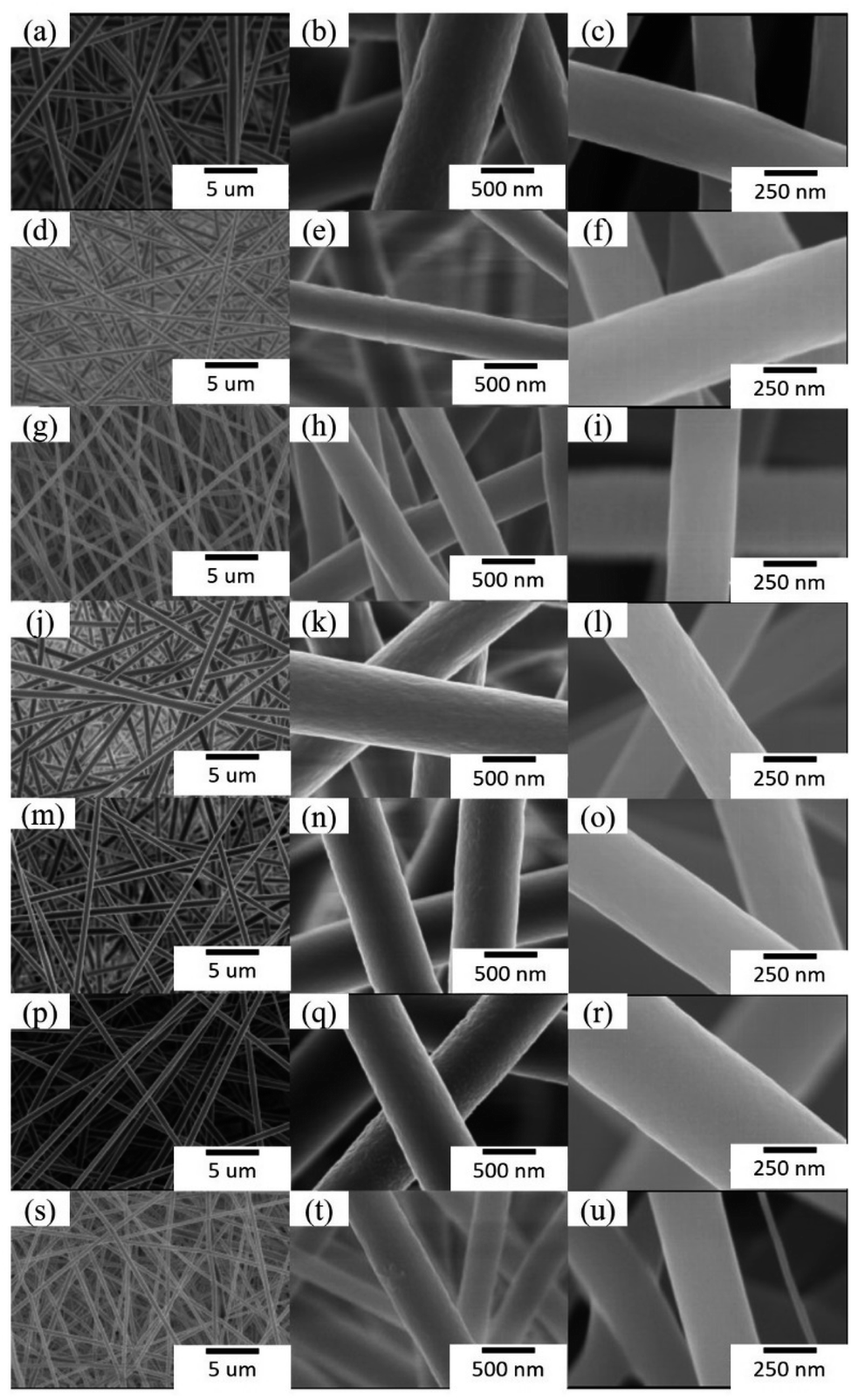
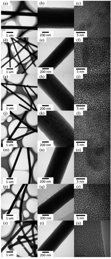
Fig. 1 shows SEM images of as-prepared nanofibrous mats before and after annealing treatment. The nanofibers in mats with either single-axial or co-axial structure were randomly oriented and uniform in diameter. No apparent bead strings or fracture marks were observed on the surface of as-prepared nanofibrous mats. The surfaces of the nanofibers became smoother after annealing treatment. The average diameter of the nanofibers was greatly affected by annealing treatment. The average diameter of the nanofibers before annealing was approximate 890.6 ± 98.4, 478 ± 37.3, 390.5 ± 26.5, 650.8 ± 26.8, 642.4 ± 49.6, 578.8 ± 74.8, 379.6 ± 40.4 nm for S1, S2, S3, C1, C2, C3, and S0, which decreased to 321.3 ± 43.4, 375.8 ± 48.8, 316.8 ± 48.2, 360.1 ± 31.6, 450.0 ± 49.1, 492.6 ± 49.4, and 263.6 ± 17.4 nm for S1-a, S2-a, S3-a, C1-a, C2-a, C3-a, and S0-a, respectively, after annealing treatment. The concentration of Fe salt in the nanofibers also affected the diameter of the carbon nanofibers. Before annealing treatment, the average diameter of the nanofibers with single-axial structure significantly decreased with increasing the concentration of such Fe salt, whereas that of the nanofibers with co-axial structure only slightly decreased. After annealing treatment, however, the average diameter of the nanofibers with single-axial structure further decreased, and such decrement was negatively related to the concentration of Fe salt encapsulated in the nanofibers. In comparison, the average diameter of the nanofibers with co-axial structure significantly increased with increasing such Fe salt concentration after the annealing treatment. The decrease of the average diameter of the nanofibers could be attributed to the further volatilization of residual solvents in the nanofibers and the carbonization of PAN molecules upon annealing treatment. The influence on the average diameter of the nanofibers induced by the concentration of Fe salt also provides an indirect evidence for the formation of ZVI NPs. In the case of the nanofibers with single-axial structure, ZVI NPs were uniformly formed after reduction annealing and encapsulated in the carbon nanofibers. Therefore, the carbon nanofibers containing ZVI NPs displayed similar diameters, although the amount of ZVI NPs in the carbon nanofiber was different. In the case of the nanofibers with co-axial structure, ZVI NPs were primarily formed in the core layer of the carbon nanofibers reduction after annealing treatment. The higher concentration of Fe salt encapsulated in the core layer of PAN nanofibers may have resulted in the formation of ZVI NPs with a larger size.
 |
| | Fig. 1 SEM images of as-prepared nanofibrous mats before (left two lanes) and after annealing treatment (right lane). (a and b) S1, (c) S1-a, (d and e) S2, (f) S2-a, (g and h) S3, (i) S3-a, (j and k) C1, (l) C1-a, (m and n) C2, (o) C2-a, (p and q) C3, (r) C3-a, (s and t) S0, (u) S0-a. | |
3.2. Phase and surface structure
Fig. 2 shows the XRD patterns and FT-IR spectra of the nanofibrous mats after annealing treatment. The broad diffraction peaks at 2θ of approximately 25° were attributed to the (002) plane of amorphous carbon.29,30 No evident diffraction peaks assigned to either iron oxides or ZVI NPs were observed in the XRD patterns of as-prepared samples, possibly attributing to the low content and extremely small size of ZVI NPs. The surface information was recorded by FT-IR spectra. Compared with the FT-IR spectrum of S0-a, the peaks near 1584 and 1306 cm−1 were shifted to higher wavenumbers of 1595 and 1385 cm−1, respectively, in FT-IR spectra of ZVI NPs-encapsulated nanofibers. These shifts could be attributed to the coordination between iron atoms and the residual carboxyl groups contained in the polymers after annealing. It is noteworthy that there is an obvious peak near 3400 cm−1 for the S1-a sample compared with the other samples, which could be derived from the hydroxy group of H2O.
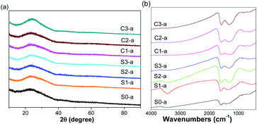 |
| | Fig. 2 XRD patterns (a) and FT-IR spectra (b) of the as-prepared nanofibrous mats after annealing. | |
3.3. Characterization of ZVI NPs
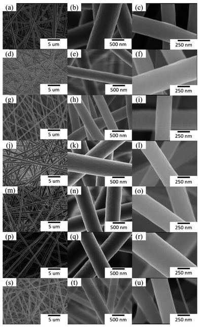
The formation of ZVI NPs was further confirmed by HRTEM characterization. As shown in Fig. 3, numerous ZVI NPs were observed on the surface of the nanofibers. The average diameter of ZVI NPs was in the range of 5–10 nm. The well aligned lattices indicate high crystallization of ZVI NPs. The average interplanar distance between adjacent lattices was approximate 0.203 ± 0.010 nm, which could be indexed to the (110) planes of Fe (JCPDS card no. 06-0696). The amount of ZVI NPs formed on the surface of the nanofibers increased with the enhancement of the Fe salt concentration in the nanofibers. It is interesting that ZVI NPs also appeared on the surface of the nanofibers with co-axial structure. We speculate that a portion of Fe ions seeped from the core layer to the sheath layer during annealing treatment and formed ZVI NPs under reduction condition. The formation of ZVI NPs in both the core layer and the sheath layer resulted in the larger diameter of the nanofibers with co-axial structure than that of the nanofibers with single-axial structure.
 |
| | Fig. 3 TEM and HRTEM images of as-prepared nanofibrous mats after annealing treatment. (a–c) S1-a, (d–f) S2-a, (g–i) S3-a, (j–l) C1-a, (m–o) C2-a, (p–r) C3-a, and (s–u) S0-a. | |
To further identify the status of ZVI NPs encapsulated in the nanofibers with different structures, XPS characterization was carried out. Fig. S1† shows the XPS spectra of as-prepared nanofibrous mats after annealing treatment. The peaks that appeared at approximate 284.5, 399, 531, and 710 eV were indexed to C 1s, N 1s, 1s, and Fe 2p, respectively. The existence of N and O could be attributed to the incomplete reduction of PAN under the annealing treatment. No signal indexed to Fe element was detected in XPS spectrum of S0-a. Fig. 4 shows the XPS spectra of Fe 2p in the nanofibers with different structures after annealing treatment. Two major peaks at approximate 709–711.3 and 723–725.6 eV could be indexed to Fe 2p3/2 and Fe 2p1/2 spin–orbit coupling, respectively. The peak of Fe 2pl/2 and Fe 2p3/2 was at approximately 724.8 and 711 eV for Fe3+ and approximately 709.5 and 723.2 eV for Fe2+, respectively.30 Hence, Fe3+/Fe2+ existed in the nanofibers, possibly attributing to the incomplete reduction of Fe salt encapsulated in the nanofibers. The characteristic peak for Fe0 at approximately 705 eV was observed in the XPS spectra of all the samples, confirming the formation and encapsulation of ZVI NPs in the nanofibers.
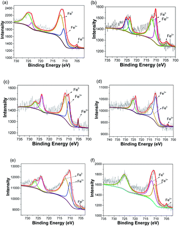 |
| | Fig. 4 XPS spectra of Fe 2p in as-prepared nanofibrous mats after annealing treatment. (a) S1-a, (b) S2-a, (c) S3-a, (d) C1-a, (e) C2-a, (f) C3-a. | |
3.4. Catalytic degradation of MB
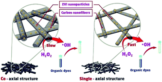
To evaluate the degradation of MB treated with as-prepared nanofibrous mats in the presence of H2O2, we monitored the absorbance of MB solution at different time intervals. pH value of solution was 7.27, 3.75, and 3.78, corresponding to MB solution, MB solution in the presence of ZVI NPs-encapsulated carbon mats and H2O2 at the time of 0 and 6 h, respectively. As shown in Fig. 5a–c, MB was completely decomposed by the nanofibrous mats with single-axial structure in the presence of H2O2 at the end of 6 h. Noticeably, the degradation rate of MB was positively related to the content of ZVI NPs encapsulated in the nanofibers. The higher the content of ZVI NPs encapsulated in the nanofibrous mat, the higher the degradation efficiency of MB. Similar results were observed in the case of treating MB solution with co-axial nanofibrous mats. At the initial 6 h, the higher content of ZVI NPs displayed a higher degradation efficiency of MB, although the entire MB in solution was completely decomposed at the end of 12 h. Thus, the degradation efficiency of MB was lower in the case of ZVI NPs encapsulated in the nanofibers with co-axial structure than that in the nanofibers with single-axial structure. Reasonably, the sheath of co-axial structure prevented the direct and fast release of Fe ions from ZVI NPs, which were encapsulated in the core of nanofibers. Therefore, ZVI NPs encapsulated in the core of the nanofibers with co-axial structure could serve as Fe reservoir for a long-term release of Fe ions.
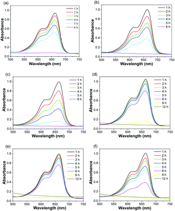 |
| | Fig. 5 UV-Vis spectra of MB solution treated with as-prepared nanofibrous mats in the presence of H2O2 at different time intervals. (a) S1-a, (b) S2-a, (c) S3-a, (d) C1-a, (e) C2-a, (f) C3-a. | |
To explore the degradation mechanism of MB under treatment with as-prepared nanofibrous mats and H2O2, we used a pseudo-first-order kinetic model to evaluate the degradation kinetic of MB, as expressed below:31,32
where
A0 represents the initial absorbance value,
At represents the absorbance value at a certain time,
k represents the apparent kinetic constant of the pseudo-first-order reaction model, and
t represents the time. Considering
t as abscissa and ln(
A0/
At) as ordinate, kinetic curves were generated for the first group, and the slope indicates the apparent kinetic constant.
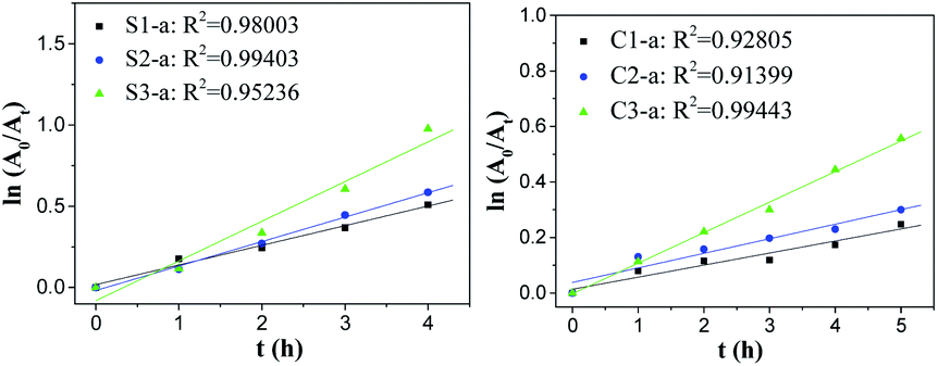
Fig. 6 shows that dye degradation reactions by the nanofibrous mats with single-axial structure have a linear relationship between ln(
A0/
At) and
t, and the correlation coefficient
R2 is close to 1, implying that dye degradation reactions catalysed by the nanofibrous mats with single-axial structure agreed with the first-order kinetic characteristics. Compared with the slope, the reaction rate constant increased as the Fe content increased, indicating that the ZVI NP content had a significant impact on dye degradation. In the case of degradation reactions catalysed by the nanofibrous mats with co-axial structure, the curves only fitted the first-order kinetic model at the initial 5 h.
Scheme 1 shows the speculated catalytic degradation of MB treated by as-prepared nanofibrous mats with either single-axial or co-axial structure. MB in the solution was decomposed by hydroxyl radicals generated by the ZVI NPs-initiated Fenton-like reaction in the presence of H
2O
2. With the consumption of ZVI NPs dispersed in the shell layer of the nanofibers, iron ions could be continuously released for ZVI NPs encapsulated in the core layer of the nanofibers due to the permeation of the acid H
2O
2 solution, which ensures the complete degradation of MB in the solution.
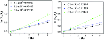 |
| | Fig. 6 Kinetic curves of degradation reactions catalysed by as-prepared nanofibrous mats with different structures. | |
 |
| | Scheme 1 The speculated degradation mechanism of MB catalysed by as-prepared carbon nanofibrous mats with either the single-axial or co-axial structure. | |
4. Conclusion
In summary, a series of PAN/Fe3+ nanofibrous mats with single-axial and co-axial structures were successfully prepared by electrospinning. ZVI NPs were formed by annealing the PAN nanofibrous mats in a reduction atmosphere and encapsulated in either single-axial or co-axial carbon nanofibers. The results on the catalytic degradation of organic dye show that the degradation rate significantly improved as the ZVI NP content encapsulated in the nanofibers increased. Moreover, the nanofibrous mats with single-axial structure displayed a higher degradation rate than those with co-axial structure, although the organic dye was completely degraded by the nanofibrous mats with either single axial structure or co-axial structure. ZVI NPs encapsulated in the core layer of the nanofibers can avoid burst release of Fe2+/Fe3+ during the practical application, thereby providing an alternative as Fe reservoir for long-term degradation of organic contaminants. Therefore, these results provide alternatives for carbon nanofibrous mats encapsulating ZVI NPs for the removal of organic dyes or heavy metal ions in environmental remediation. In a short-term and emergent situation, carbon nanofibrous mats with single-axial structure can catalytically degrade organic dyes quickly, whereas in a long-term and protective situation, carbon nanofibrous mats with co-axial structure can be utilized as the Fe reservoir for controlled degradation of organic dyes.
Conflicts of interest
There are no conflicts to declare.
Acknowledgements
This research was financially supported by National Key Research and Development (R&D) Program of China (No. 2018YFB1105702).
References
- A. Stolz, Basic and applied aspects in the microbial degradation of azo dyes, Appl. Microbiol. Biotechnol., 2001, 56, 69–80 CrossRef CAS.
- E. Brillas and S. Garcia-Segura, Benchmarking recent advances and innovative technology approaches of Fenton, photo-Fenton, electro-Fenton, and related processes: a review on the relevance of phenol as model molecule, Sep. Purif. Technol., 2020, 237, 116337 CrossRef CAS.
- Z. Mao, Q. Wu, M. Wang, Y. Yang, J. Long and X. Chen, Tunable synthesis of SiO2-encapsulated zero-valent iron nanoparticles for degradation of organic dyes, Nanoscale Res. Lett., 2014, 9, 501–509 CrossRef.
- F. Lu and D. Astruc, Nanocatalysts and other nanomaterials for water remediation from organic pollutants, Coord. Chem. Rev., 2020, 408, 213180 CrossRef CAS.
- M. Wang, Y. Yang, J. Long, Z. Mao, T. Qiu, Q. Wu and X. Chen, Synthesis of Pt3Ni microspheres with high performance for rapid degradation of organic dyes, Nanoscale Res. Lett., 2015, 10, 231–236 CrossRef.
- J. F. Li, Y. B. Chen, Z. Wang and Z. Q. Liu, Self-templating synthesis of hollow copper tungstate spheres as adsorbents for dye removal, J. Colloid Interface Sci., 2018, 526, 459–469 CrossRef CAS.
- R. B. Wei, Z. L. Huang, G. H. Gu, Z. Wang, L. X. Zeng, Y. B. Chen and Z. Q. Liu, Dual-cocatalysts decorated rimous CdS spheres advancing highly-efficient visible-light photocatalytic hydrogen production, Appl. Catal., B, 2018, 231, 101–107 CrossRef CAS.
- S. He, C. Yan, X. Z. Chen, Z. Wang, T. Ouyang, M. L. Guo and Z. Q. Liu, Construction of core-shell heterojunction regulating α-Fe2O3 layer on CeO2 nanotube arrays enables highly efficient Z-scheme photoelectrocatalysis, Appl. Catal., B, 2020, 276, 119138 CrossRef CAS.
- S. Chen and A. S. Y. Ting, Biodecolorization and biodegradation potential of recalcitrant triphenylmethane dyes by Coriolopsis sp isolated from compost, J. Environ. Manage., 2015, 150, 274–280 CrossRef CAS.
- G. McMullan, C. Meehan, A. Conneely, N. Kirby, T. Robinson, P. Nigam, I. Banat, R. Marchant and W. Smyth, Microbial decolourisation and degradation of textile dyes, Appl. Microbiol. Biotechnol., 2001, 56, 81–87 CrossRef CAS.
- T. Robinson, G. McMullan, R. Marchant and P. Nigam, Remediation of dyes in textile effluent: a critical review on current treatment technologies with a proposed alternative, Bioresour. Technol., 2001, 77, 247–255 CrossRef CAS.
- Y. Gan, N. Tian, X. Tian, L. Ma, W. Wang, C. Yang, Z. Zhou and Y. Wang, Adsorption behavior of methylene blue on amine-functionalized ordered mesoporous alumina, J. Porous Mater., 2014, 292, 147–155 Search PubMed.
- S. K. Sonar, P. S. Niphadkar, S. Mayadevi and P. N. Joshi, Preparation and characterization of porous fly ash/NiFe2O4 composite: promising adsorbent for the removal of Congo red dye from aqueous solution, Mater. Chem. Phys., 2014, 148, 371–379 CrossRef CAS.
- J. B. De Heredia, J. Torregrosa, J. R. Dominguez and J. A. Peres, Kinetic model for phenolic compound oxidation by Fenton's reagent, Chemosphere, 2001, 45, 85–90 CrossRef CAS.
- Y. Dong, Z. Han, C. Liu and F. Du, Preparation and photocatalytic performance of Fe (III)- amidoximated PAN fiber complex for oxidative degradation of azo dye under visible light irradiation, Sci. Total Environ., 2010, 408, 2245–2253 CrossRef CAS.
- E. Khan, W. Wirojanagud and N. Sermsaid, Effects of iron type in Fenton reaction on mineralization and biodegradability enhancement of hazardous organic compounds, J. Hazard. Mater., 2009, 161, 1024–1034 CrossRef CAS.
- D. Baragano, J. Alonso, J. R. Gallego, M. C. Lobo and M. Gil-Diaz, Zero valent iron and goethite nanoparticles as new promising remediation techniques
for as-polluted soils, Chemosphere, 2020, 238, 124624 CrossRef CAS.
- R. Huang, Z. Fang, X. Yan and W. Cheng, Heterogeneous sono-Fenton catalytic degradation of bisphenol: A by Fe3O4 magnetic nanoparticles under neutral condition, Chem. Eng. J., 2012, 197, 242–249 CrossRef CAS.
- Q. Du, G. X. Li, S. S. Zhang, J. P. Song, Y. Zhao and F. Yang, High-dispersion zero-valent iron particles stabilized by artificial humic acid for lead ion removal, J. Hazard. Mater., 2020, 383, 121170 CrossRef CAS.
- G. P. Pei, Y. Zhu, J. G. Wen, Y. X. Pei and H. Li, Vinegar residue supported nanoscale zero-valent iron: remediation of hexavalent chromium in soil, Environ. Pollut., 2020, 256, 113407 CrossRef CAS.
- N. Zhou, K. D. Gong, Q. Hu, X. Cheng, J. Y. Zhou, M. Y. Dong, N. Wang, T. Ding, B. Qiu and Z. H. Guo, Optimizing nanocarbon shell in zero-valent iron nanoparticles for improved electron utilization in Cr(VI) reduction, Chemosphere, 2020, 242, 125235 CrossRef CAS.
- A. Praetorius, E. Badetti, A. Brunelli, A. Clavier, J. A. G. Gallego-Urrea, A. Gondikas, M. Hassellov, T. Hofmann, A. Mackevica, A. Marcomini, W. Peijnenburg, J. T. K. Quik, M. Seijo, S. Stoll, N. Tepe, H. Walch and F. von der Kammer, Strategies for determing heteroaggregation attachment efficiencies of engineered nanoparticles in aquatic environments, Environ. Sci.: Nano, 2020, 7, 351–367 RSC.
- R. Stepanyan, A. Subbotin, L. Cuperus and P. Boonen, Fiber diameter control in electrospinning, Appl. Phys. Lett., 2014, 105, 43–47 CrossRef.
- C. J. Thompson, G. G. Chase, A. L. Yarin and D. H. Reneker, Effects of parameters on nanofiber diameter determined from electrospinning model, Polymers, 2007, 48, 6913–6922 CrossRef CAS.
- Z. Mao, J. Li, W. Huang, B. Zimba, H. Jiang, L. Chen, J. Wan and Q. Wu, Preparation of poly(lactic acid)/graphene oxide nanofiber membranes with different structures by electrospinning for drug delivery, RSC Adv., 2018, 8, 16619–16625 RSC.
- Z. Sun, E. Zussman, A. L. Yarin, J. H. Wendorff and A. Greiner, Compound core-shell polymer nanofibers by co-electrospinning, Adv. Mater., 2003, 15, 1929–1932 CrossRef CAS.
- Z. M. Huang, C. L. He and A. Yang, Encapsulating drugs in biodegradable ultrafine fibers through co-axial electrospinning, J. Biomed. Mater. Res., Part A, 2006, 77, 169–179 CrossRef.
- A. L. Yarin, Coaxial electrospinning and emulsion electrospinning of core-shell fibers, Polym. Adv. Technol., 2011, 22, 310–317 CrossRef CAS.
- J. Jin, B. J. Yu, Z. Q. Shi, C. Y. Wang and C. B. Chong, Lignin-based electrospun carbon nanofibrous webs as free-standing and binder-free electrodes for sodium ion batteries, J. Power Sources, 2014, 272, 800–807 CrossRef CAS.
- T. Amashita and P. Hayes, Analysis of XPS spectra of Fe2+ and Fe3+ ions in oxide materials, Appl. Surf. Sci., 2008, 254, 2441–2449 CrossRef.
- C. P. Bai, W. Q. Gong, D. X. Feng, M. Xian, Q. Zhou, S. H. Chen, Z. X. Ge and Y. S. Zhou, Natural graphite tailings as heterogeneous Fenton catalyst for the decolorization of rhodamine B, Chem. Eng. J., 2012, 197, 306–313 CrossRef CAS.
- C. R. Keenan and D. L. Sedlak, Factors affecting the yield of oxidants from the reaction of nanoparticulate zero-valent iron and oxygen, Environ. Sci. Technol., 2008, 42, 1262–1267 CrossRef CAS.
Footnote |
| † Electronic supplementary information (ESI) available. See DOI: 10.1039/d0ra10235k |
|
| This journal is © The Royal Society of Chemistry 2021 |
Click here to see how this site uses Cookies. View our privacy policy here. 
 Open Access Article
 This Open Access Article is licensed under a Creative Commons Attribution-Non Commercial 3.0 Unported Licence
 *a
*a