 Open Access Article
TiO2-Based photocatalyst modified with a covalent triazine-based framework organocatalyst for carbamazepine photodegradation
Xiaofang Chao,
Yaqian Xu,
Hui Chen,
Diejing Feng,
Jinxing Hu and
Yan Yu *
*
College of Science & Technology Ningbo University, Ningbo University, Ningbo City, China. E-mail: 2111405018@zjut.edu.cn
First published on 10th February 2021
Abstract
A novel fluorine-doped TiO2 (TiO2−XFX) heterojunction semiconductor photocatalyst was synthesised using covalent triazine-based frameworks (CTFs) at different weight ratios. X-ray photoelectron spectroscopy revealed that doping with CTFs shifts the value of the TiO2−XFX catalyst to a lower binding energy, which led to the bandgap narrowing. From the results of the photocatalytic activity and Fourier-transform infrared spectroscopy, a rise in carbamazepine (CBZ) adsorption under dark conditions and an increased intensity of characteristic triazine units after exfoliation were observed, which indicated that the addition of nanosheet CTFs would increase the number of active sites. Furthermore, the results showed that the TiO2−XFX/CTFs photocatalyst was almost 5.5 times better than pure TiO2−XFX in the removal of CBZ under visible light owing to the narrowed bandgap, the increased active sites, the quick separation of photo-generated carriers, and improved light absorption. A mechanism for photodegradation of CBZ with the TiO2−XFX/CTFs photocatalyst was proposed.
Introduction
TiO2-Based semiconductor photocatalysts have been widely studied owing to their low toxicity, low-cost, and high physicochemical stability.1–8 However, the main disadvantages of TiO2-based photocatalysts are their wide bandgaps (3.0 eV for rutile and 3.2 eV for anatase),1 and high electron–hole pair recombination rates.9,10 Therefore, doping with metal or nonmetal elements, such as transition metals and nonmetal anions, has been introduced to avoid these disadvantages.11–14 However, anionic dopants such as N-doped TiO2 reduce the photocatalytic activity if the nitrogen content exceeds a certain value.15 It was observed that F-doped TiO2 only had a slight effect on narrowing the bandgap.1 Transition-metal cations inefficiently separate electron and hole pairs, as they present recombination centres for photocatalytic carriers.16,17 Moreover, metal doping can have the drawback of thermal instability.18 Therefore, the synergistic effect with other organic semiconductor catalysts, such as metal–organic frameworks (MOFs)19,20 and covalent organic frameworks (COFs), can lower the bandgap and lower contamination.21–24Among multiple attractive organic semiconductors photocatalysts, covalent triazine-based frameworks (CTFs), which possess a wide visible-light adsorption band, a tunable band structure,25 high chemical and thermal stability, low toxicity, a relatively narrow bandgap (2.4 eV),27–29 and cheap,26 have been considered as a suitable co-catalyst for TiO2-based photocatalysts. However, CTFs have similar problems, such as fast photogenerated carrier recombination, to other photocatalysts.30–32 The synthesis of heterostructures could enhance the separation of the electron–hole pairs,33–40 thus improving the photocatalytic performance.
In this work, we have modified TiO2−XFX with CTFs using different weight ratios. The synergistic effect of TiO2−XFX/CTFs was investigated through photocatalytic degradation of a typical pharmaceutical carbamazepine (CBZ) under simulated sunlight irradiation (λ > 420 nm). Moreover, physicochemical characterisation, such as scanning electron microscopy (SEM), Brunauer–Emmett–Teller (BET) N2 adsorption–desorption, X-ray diffraction (XRD), Fourier-transform infrared spectroscopy (FTIR), and X-ray photoelectron spectroscopy (XPS) were performed and discussed.
Experimental methods
Materials
Tetrabutyl titanate (C16H36O4Ti), 1,4-dicyanobenzene (DCB), trifluoromethanesulfonic acid (TFMS), N,N-dimethylformamide (DMF), potassium monopersulfate triple salt (PMS, KHSO5·0.5KHSO4·0.5K2SO4), CBZ, methanol, and sodium hydroxide (NaOH) were supplied by Shanghai Aladdin Biochemical Technology Co., Ltd. Ethanol (EtOH) was obtained from Shanghai Titan Scientific Co., Ltd. Hydrofluoric Acid (HF) was purchased from Kunshan Jincheng Reagent Co., Ltd.Synthesis of TiO2−XFX
The fluorine-doped TiO2 (TiO2−XFX) nanosheets were fabricated by a simple hydrothermal method. C16H36O4Ti (50 mL) was dissolved in a HF solution (40 wt%, 10 mL), and the mixture was heated in a Teflon-lined autoclave (100 mL) at 240 °C for 24 h after stirring for 30 min at ambient temperature. The precipitation products were obtained using centrifugation and washed three times with ethanol and ultrapure water. The sky blue photocatalyst was obtained after drying in an oven at 80 °C for 12 h.Synthesis of CTFs
DCB (98 wt%, 4 mmol) was dissolved in TFMS (2.5 mL) under N2 at 0 °C. Then silica microspheres (0.5 g) were added to the mixture with continuous stirring for 1.5 h at 0 °C. Thereafter, the synthesised products (SiO2@CTFs), were heated to 100 °C for 20 min, obtained by centrifugation, and washed several times with ultrapure water and ethanol. Subsequently, the composite was dried in a vacuum overnight at 60 °C. H-CTF-Na photocatalysts were synthesised with NaOH (0.5 M) under hydrothermal conditions for 5 h at 60 °C. The products were obtained following centrifugation, washing with ultrapure water and ethanol until neutral, and then dried in a vacuum for 12 h at 60 °C.Synthesis of TiO2−XFX/CTFs heterojunction photocatalyst
Two types of semiconductor photocatalysts were synthesised through different synthesis methods. In brief, a TiO2−XFX/CTFs van der Waals heterojunction was produced using an ultrasonic and mechanical method. The TiO2−XFX/CTFs mixture was added into a DMF aqueous dispersion (50 mL) and stirred for 2 h. Thereafter, the sample was sonicated for 1 h, washed with ethanol three times, and finally dried in a vacuum overnight at 50 °C. To optimise the photocatalytic characteristic, TiO2−XFX/CTFs was synthesised with three different weight ratios between TiO2−XFX and CTFs (1![[thin space (1/6-em)]](https://www.rsc.org/images/entities/char_2009.gif) :
:![[thin space (1/6-em)]](https://www.rsc.org/images/entities/char_2009.gif) 0.2, 1
0.2, 1![[thin space (1/6-em)]](https://www.rsc.org/images/entities/char_2009.gif) :
:![[thin space (1/6-em)]](https://www.rsc.org/images/entities/char_2009.gif) 0.5, and 1
0.5, and 1![[thin space (1/6-em)]](https://www.rsc.org/images/entities/char_2009.gif) :
:![[thin space (1/6-em)]](https://www.rsc.org/images/entities/char_2009.gif) 1).
1).
Characterisation
The crystal structures of the synthesised composites were examined using XRD (X'Pert Pro MPD, Panalytical, Netherlands) with a Cu Kα X-ray radiation source (60 kV and 55 mA). The morphology and textural properties of different samples were determined using SEM (SU8010, Hitachi, Japan). The Brunauer–Emmett–Teller (BET) was used to record the surface area with N2 adsorption–desorption isotherms on an ASAP 2020 system (Micromeritics, USA). FTIR spectra (Thermo Scientific, USA) was measured on a Nicolet iS 10 spectrometer. XPS (Thermo Scientific K-Alpha, USA) was recorded to analyse the surface chemical environments. The excitation source was Al Kα (hv = 1486.6 eV) and the X-ray gun was operated at 72 W (12 kV, 6 mA).Photocatalytic reaction
The photocatalytic activity of three prepared TiO2−XFX/CTFs catalysts and pure TiO2−XFX were examined through the photodegradation of carbamazepine (CBZ) in aqueous solutions with simulated sunlight irradiation. The solution of CBZ (5 mg L−1) was prepared and diluted with deionised water to desirable experimental concentrations. The experiments were performed using a CEL-S500/350 Xe lamp (Beijing CeauLight Co., Ltd, China) with an optical cut-off filter (λ > 420 nm). A thermostat (DFY-5L/40, Gongyi City Yuhua Instrument Co., Ltd, China) was applied to preserve the invariable temperature at 25 °C.Before mixing with the four different photocatalysts, PMS (40 mg) was added to a CBZ aqueous solution (100 mL, 5 mg L−1) in a photo-reactor. The suspension was continuously stirred under dark conditions for 30 min at 25 °C to establish an adsorption–desorption equilibrium. Thereafter, the Xe lamp was turned on to start the photocatalytic reaction, and then during the photocatalytic reaction, aliquots (1.0 mL) were taken and filtrated at certain intervals using a syringe filter (0.22 μm). The concentration of the filtered solution was detected using mass spectrometry (Agilent HPLC-1260 with a C18 column (4.6 mm × 150 mm, 4 μm) and a UV detector). The mobile phase was methanol (80%) in ultrapure water (flow rate of 1.0 mL min−1), the column temperature was 40 °C, and the detection wavelength was 285 nm.
Result and discussion
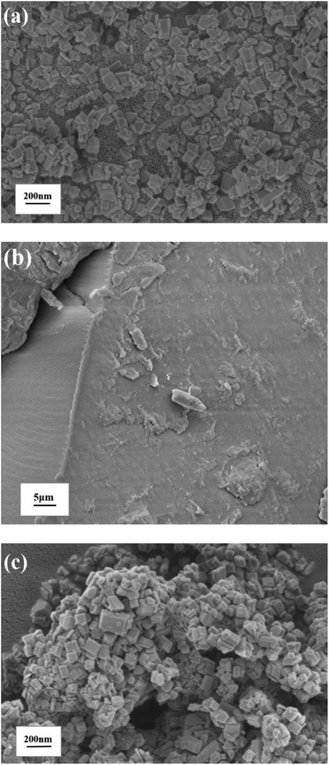
Fig. 1 showed SEM images of pure TiO2−XFX, pure CTFs and the combination of two catalysts. In Fig. 1a, TiO2−XFX demonstrated a uniform octahedral sheet structure1 and CTFs displayed a structure with a rough surface (Fig. 1b). SEM images of TiO2−XFX/CTFs heterojunctions were shown in Fig. 1c, in which the agglomerate structure of TiO2−XFX was exhibited.TEM
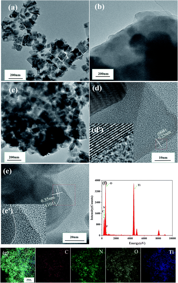
Transmission electron microscopy (TEM) was performed to reveal the crystallographic properties of pristine TiO2−XFX, pristine CTFs, and the synthesised TiO2−XFX/CTFs with a weight ratio 1![[thin space (1/6-em)]](https://www.rsc.org/images/entities/char_2009.gif) :
:![[thin space (1/6-em)]](https://www.rsc.org/images/entities/char_2009.gif) 1 at an atomic scale (Fig. 2a–c). TEM images indicated that TiO2−XFX possesses the regular octahedral shape (Fig. 2a), the CTFs edge showed a layered structure (Fig. 2b), and the TiO2−XFX/CTFs (1
1 at an atomic scale (Fig. 2a–c). TEM images indicated that TiO2−XFX possesses the regular octahedral shape (Fig. 2a), the CTFs edge showed a layered structure (Fig. 2b), and the TiO2−XFX/CTFs (1![[thin space (1/6-em)]](https://www.rsc.org/images/entities/char_2009.gif) :
:![[thin space (1/6-em)]](https://www.rsc.org/images/entities/char_2009.gif) 1) catalyst demonstrated a combination of the two substances (Fig. 2c). As shown in Fig. 2d and e, to further investigate the structure of TiO2−XFX/CTFs (1
1) catalyst demonstrated a combination of the two substances (Fig. 2c). As shown in Fig. 2d and e, to further investigate the structure of TiO2−XFX/CTFs (1![[thin space (1/6-em)]](https://www.rsc.org/images/entities/char_2009.gif) :
:![[thin space (1/6-em)]](https://www.rsc.org/images/entities/char_2009.gif) 1), we enlarged the selected regions (red box) with the inverse fast Fourier transform (IFFT) images (Fig. 2d and e). The IFFT image revealed regular lattice fringes with a d-spacing of 0.23 and 0.35 nm, corresponding to the (004) plane and (101) plane of anatase.41 The IFFT image also displayed the CTFs layer extending to the border in Fig. 2e.
1), we enlarged the selected regions (red box) with the inverse fast Fourier transform (IFFT) images (Fig. 2d and e). The IFFT image revealed regular lattice fringes with a d-spacing of 0.23 and 0.35 nm, corresponding to the (004) plane and (101) plane of anatase.41 The IFFT image also displayed the CTFs layer extending to the border in Fig. 2e.
Furthermore, energy-dispersive X-ray spectroscopy (EDS) (Fig. 2f) revealed that TiO2−XFX/CTFs mainly consists of C, N, O, Ti, and F. The element mapping images of TiO2−XFX/CTFs (1![[thin space (1/6-em)]](https://www.rsc.org/images/entities/char_2009.gif) :
:![[thin space (1/6-em)]](https://www.rsc.org/images/entities/char_2009.gif) 1) (Fig. 2g) showed that C (deep red), N (green), O (yellow), and Ti (deep blue) were evenly dispersed, which confirmed that TiO2−XFX and CTFs were well combined. These results were further demonstrated by XRD and XPS analyses.
1) (Fig. 2g) showed that C (deep red), N (green), O (yellow), and Ti (deep blue) were evenly dispersed, which confirmed that TiO2−XFX and CTFs were well combined. These results were further demonstrated by XRD and XPS analyses.
BET
N2 adsorption–desorption measurements shown in Fig. 3 indicated the porosity of the four photocatalysts. The samples exhibited a type IV isotherm and H3 hysteresis loop.1 The plunge in the desorption curve and the hysteresis loop at high relative pressure indicated the mesoporosity of the samples (Fig. 3a). The pore size distributions (Fig. 3b), which were acquired using the BJH (Barret–Joyner–Halenda) method, indicated that the samples have a wide pore distribution range (10–130 nm).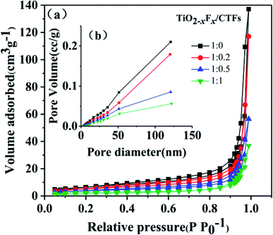 | ||
| Fig. 3 (a) N2 adsorption–desorption isotherms and (b) pore-size distribution of the TiO2−XFX/CTFs photocatalysts. | ||
The BET specific surface area, total pore volume, and average pore diameter of the four catalysts were shown in Table 1. With an increase in CTF concentration, a slight decrease in BET surface area and pore volume was seen. This indicated that the addition of CTFs might result in a relatively dense organic framework through agglomeration, which was indicated by SEM images, and led to smaller mesopore size and lower surface area.
| TiO2−XFX/CTFs | BET surface areas (m2 g−1) | Total pore volume (cc g−1) | Average pore diameter (nm) |
|---|---|---|---|
1![[thin space (1/6-em)]](https://www.rsc.org/images/entities/char_2009.gif) : :![[thin space (1/6-em)]](https://www.rsc.org/images/entities/char_2009.gif) 0 0 |
23.283 | 0.212 | 36.42 |
1![[thin space (1/6-em)]](https://www.rsc.org/images/entities/char_2009.gif) : :![[thin space (1/6-em)]](https://www.rsc.org/images/entities/char_2009.gif) 0.2 0.2 |
18.785 | 0.1811 | 38.56 |
1![[thin space (1/6-em)]](https://www.rsc.org/images/entities/char_2009.gif) : :![[thin space (1/6-em)]](https://www.rsc.org/images/entities/char_2009.gif) 0.5 0.5 |
13.523 | 0.08727 | 25.81 |
1![[thin space (1/6-em)]](https://www.rsc.org/images/entities/char_2009.gif) : :![[thin space (1/6-em)]](https://www.rsc.org/images/entities/char_2009.gif) 1 1 |
9.357 | 0.057 | 24.37 |
XRD
Three TiO2−XFX/CTFs photocatalysts with different weight ratios and a pure TiO2−XFX catalyst were analysed using XRD. Fig. 4a showed the diffraction peaks which corresponded to the TiO2 crystalline phase of anatase. The diffraction peaks at approximately 25.3°, 37.8°, 48.1°, 53.9°, 55.1°, 62.7°, 68.7°, 70.3°, and 75.1° correspond to the crystal planes of (101), (004), (200), (105), (211), (204), (116), (220), and (215), respectively.42 An increase in the characteristic peak for CTFs was observed in the XRD patterns (Fig. 4b). The main increased intensity was observed at around 27.0°, which indicated the crystal plane of the π-conjugated bond rings.43 These results indicated the presence of both photocatalysts. With decreasing weight ratio of TiO2−XFX/CTFs from 1![[thin space (1/6-em)]](https://www.rsc.org/images/entities/char_2009.gif) :
:![[thin space (1/6-em)]](https://www.rsc.org/images/entities/char_2009.gif) 0.2 to 1
0.2 to 1![[thin space (1/6-em)]](https://www.rsc.org/images/entities/char_2009.gif) :
:![[thin space (1/6-em)]](https://www.rsc.org/images/entities/char_2009.gif) 1, the intensity of anatase decreased. Meanwhile, the intensity of CTFs was improved.
1, the intensity of anatase decreased. Meanwhile, the intensity of CTFs was improved.
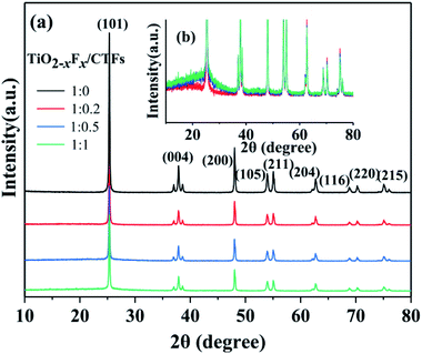 | ||
| Fig. 4 (a) X-ray diffraction patterns of different photocatalysts and (b) enlarged XRD patterns of the TiO2−XFX/CTFs photocatalysts with different weight ratios. | ||
FTIR
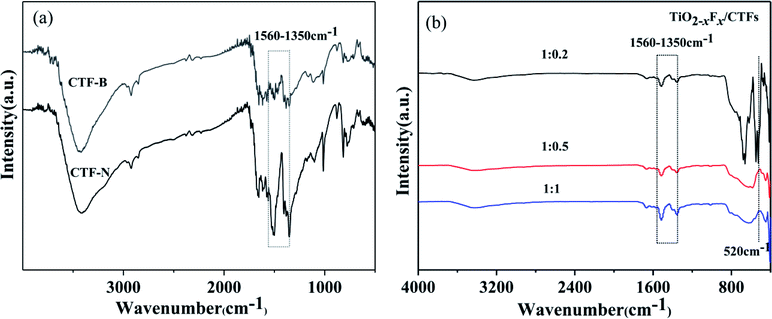
To investigate the impact of exfoliation on bulk CTFs through sonication, FTIR was measured. As shown in Fig. 5a, the characteristic bands for triazine (1560–1350 cm−1) were seen for bulk CTFs and nanosheet CTFs.26,44–47 Compared with bulk CTFs, an increased intensity for the adsorption peak corresponding to triazine in the nanosheet CTFs was observed, which indicated that by exfoliating bulk CTFs to form nanosheet CTFs, triazine was exposed on the surface of CTFs. FTIR analysis of the photocatalysts indicated the successful formation of triazine (Fig. 5b). All samples showed a strong adsorption band at approximately 1560–1350 cm−1, which corresponded to the triazine unit.26,44–47 A strong adsorption band at approximately 520 cm−1, which corresponded to the Ti–O stretching band, was demonstrated when the TiO2−XFX/CTFs weight ratio is at 1![[thin space (1/6-em)]](https://www.rsc.org/images/entities/char_2009.gif) :
:![[thin space (1/6-em)]](https://www.rsc.org/images/entities/char_2009.gif) 0.2.48 However, for the weight ratios 1
0.2.48 However, for the weight ratios 1![[thin space (1/6-em)]](https://www.rsc.org/images/entities/char_2009.gif) :
:![[thin space (1/6-em)]](https://www.rsc.org/images/entities/char_2009.gif) 0.5 and 1
0.5 and 1![[thin space (1/6-em)]](https://www.rsc.org/images/entities/char_2009.gif) :
:![[thin space (1/6-em)]](https://www.rsc.org/images/entities/char_2009.gif) 1, the Ti–O stretching band was hardly visible.
1, the Ti–O stretching band was hardly visible.
XPS
The XPS survey spectra of the photocatalysts indicated that they contained C, N, Ti, O, and F (Fig. 6a). As shown in Fig. 6b, the XPS spectra of the C 1s region of the photocatalysts revealed three peaks. The strongest signal at 284.8 eV was assigned to the carbon atoms in aromatic rings and used as the reference carbon for calibrating the XPS instrument.44 The second peak was at approximately 287.0 eV and was assigned to the N–C![[double bond, length as m-dash]](https://www.rsc.org/images/entities/char_e001.gif) N bond in triazine.49 The third peak centred at approximately 288.4 eV corresponds to the carbon in C–N groups.49 The N 1s spectra were resolved into two individual peaks located at around 398.9 eV and 400.0 eV (Fig. 6c), which were assigned to the N atoms in C–N
N bond in triazine.49 The third peak centred at approximately 288.4 eV corresponds to the carbon in C–N groups.49 The N 1s spectra were resolved into two individual peaks located at around 398.9 eV and 400.0 eV (Fig. 6c), which were assigned to the N atoms in C–N![[double bond, length as m-dash]](https://www.rsc.org/images/entities/char_e001.gif) C of triazine,26,44 and the pyrrolic-like nitrogen (C–N–C) deriving from the decomposition of triazine, respectively.50 For the TiO2−XFX/CTFs photocatalyst, the peak at approximately 399.0 eV was shifted to a higher binding energy compared to pristine CTFs.
C of triazine,26,44 and the pyrrolic-like nitrogen (C–N–C) deriving from the decomposition of triazine, respectively.50 For the TiO2−XFX/CTFs photocatalyst, the peak at approximately 399.0 eV was shifted to a higher binding energy compared to pristine CTFs.
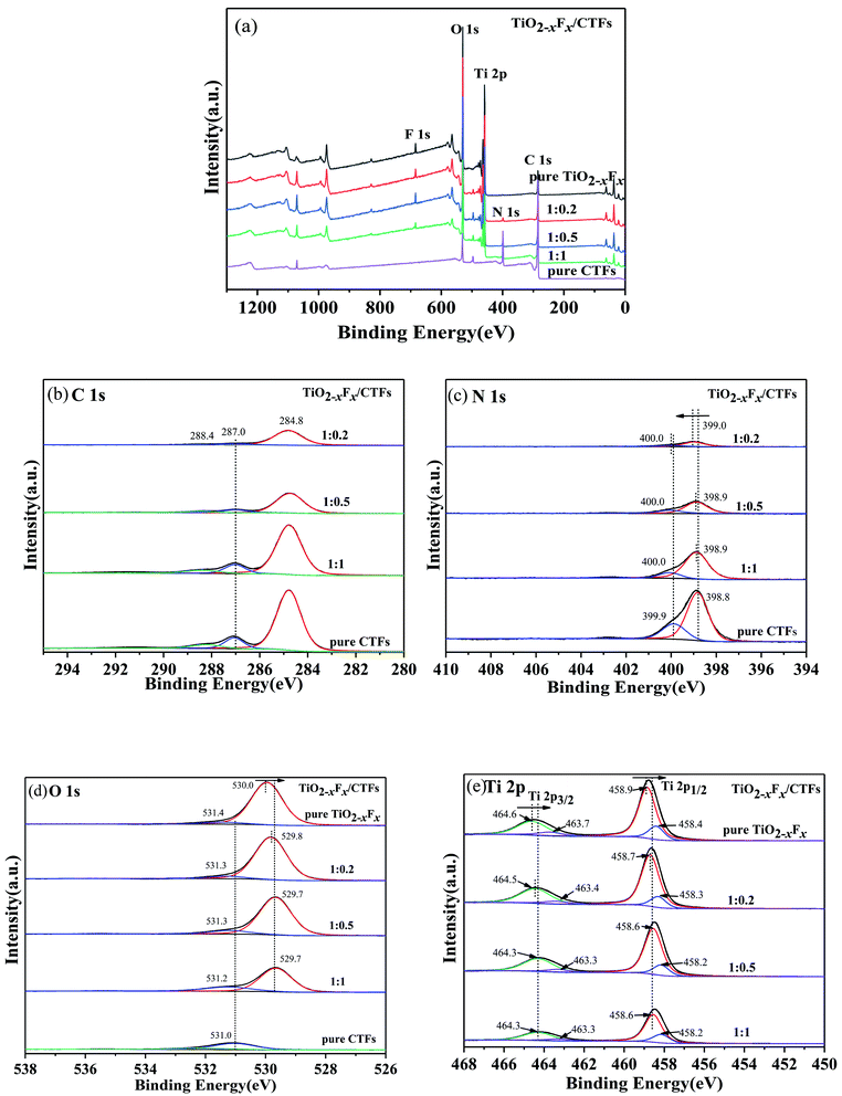 | ||
| Fig. 6 (a) X-ray survey and high-resolution spectrum for (b) C 1s, (c) N 1s, (d) O 1s, and (e) Ti 2p. | ||
The O 1s spectra were deconvoluted into two peaks at the binding energies of 529.7 eV and 531.2 eV (Fig. 6d), which were assigned to Ti–O in TiO2−XFX1 and to surface hydroxyl in adsorbed H2O molecules, respectively.41,51 The oxygen peak located at 529.7 eV was shifted slightly to lower binding presence of oxygen vacancies.41 The Ti 2p XPS spectra were shown in Fig. 6e and could be fitted by four peaks at approximately 458.4 eV, 458.9 eV, 463.3 eV, and 464.5 eV. The peaks at binding energies of 458.9 and 464.5 eV corresponded to the signals of Ti 2p1/2 and Ti 2p3/2 of Ti4+, respectively, whereas the two peaks at 458.4 eV and 463.3 eV corresponded to the signals of Ti 2p1/2 and Ti 2p3/2 of Ti3+, respectively.52 The Ti 2p region was shifted slightly to lower binding energy compared with pristine TiO2−XFX.
Therefore, by comparing the TiO2−XFX/CTFs photocatalyst with pristine TiO2−XFX and CTFs, the N 1s binding energy increased, whereas the Ti 2p binding energy decreased. These shifted peaks indicated a strong synergetic effect between TiO2−XFX and CTFs and the transference of electrons from CTFs to TiO2−XFX, which indicated the successful combination of the two photocatalysts.
The effect of TiO2−XFX/CTFs on CBZ photocatalytic degradation
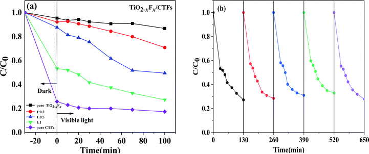
To investigate the photocatalytic activity of the catalysts, the degradation of CBZ in the presence of PMS irradiated under visible light was performed. It is well-known that PMS cannot degrade CBZ effectively without a catalyst. The results of these measurements were shown in Fig. 7a.After treatment under dark conditions for 30 min, the TiO2−XFX/CTFs catalysts had a higher CBZ adsorption than pure TiO2−XFX catalyst (approximately 4.7%). Notably, for the catalyst with 50% CTF, the degradation efficiency was 46.7%, which is almost 10 times higher than pure TiO2−XFX. In this study, the degradation efficiency of the TiO2−XFX/CTFs catalyst was enhanced owing to the presence of Ti3+ and triazine units, which provide a large number of active sites,51–53 thus improving CBZ absorption.
Under visible light, the degradation efficiency of the TiO2−XFX and CTFs catalysts with weight ratios 1![[thin space (1/6-em)]](https://www.rsc.org/images/entities/char_2009.gif) :
:![[thin space (1/6-em)]](https://www.rsc.org/images/entities/char_2009.gif) 0, 1
0, 1![[thin space (1/6-em)]](https://www.rsc.org/images/entities/char_2009.gif) :
:![[thin space (1/6-em)]](https://www.rsc.org/images/entities/char_2009.gif) 0.2, 1
0.2, 1![[thin space (1/6-em)]](https://www.rsc.org/images/entities/char_2009.gif) :
:![[thin space (1/6-em)]](https://www.rsc.org/images/entities/char_2009.gif) 0.5, 1
0.5, 1![[thin space (1/6-em)]](https://www.rsc.org/images/entities/char_2009.gif) :
:![[thin space (1/6-em)]](https://www.rsc.org/images/entities/char_2009.gif) 1, and 0
1, and 0![[thin space (1/6-em)]](https://www.rsc.org/images/entities/char_2009.gif) :
:![[thin space (1/6-em)]](https://www.rsc.org/images/entities/char_2009.gif) 1 was 13.3%, 29.2%, 50.5%, 72.8%, and 82.7%, respectively, within 100 min of irradiation. These results showed that there was an increase in CBZ degradation with an increase in the weight ratio of CTFs. In addition, the trend of CBZ degradation efficiency of the pure CTFs was similar to that of the pure TiO2−XFX, there was no significant degradation trend when compared to the TiO2−XFX/CTFs heterojunction catalyst in the visible light region, which indicated that the synthesis of heterostructures could decrease the recombination of the electron–hole pairs, thus improving photocatalytic performance.
1 was 13.3%, 29.2%, 50.5%, 72.8%, and 82.7%, respectively, within 100 min of irradiation. These results showed that there was an increase in CBZ degradation with an increase in the weight ratio of CTFs. In addition, the trend of CBZ degradation efficiency of the pure CTFs was similar to that of the pure TiO2−XFX, there was no significant degradation trend when compared to the TiO2−XFX/CTFs heterojunction catalyst in the visible light region, which indicated that the synthesis of heterostructures could decrease the recombination of the electron–hole pairs, thus improving photocatalytic performance.
The bandgaps of TiO2−XFX and CTFs are 3.13 eV1 and 1.85–1.50 eV,54 respectively. The shift of the O 1s and Ti 2p XPS peaks to lower binding energy demonstrated that the presence of CTFs could decrease the bandgap. As mentioned above, the cooperative effect of CTFs not only exposes a large number of active sites, but also significantly narrows the bandgap, thus decreasing the photo-generated charge transfer distance, and increasing visible light adsorption, so that the recombination of the electrons and holes is impeded, which improves the photocatalytic activity.
To further evaluate the stability of the TiO2−XFX/CTFs heterojunction photocatalyst, recyclability tests for CBZ photodegradation were performed on a representative TiO2−XFX/CTFs catalyst (1![[thin space (1/6-em)]](https://www.rsc.org/images/entities/char_2009.gif) :
:![[thin space (1/6-em)]](https://www.rsc.org/images/entities/char_2009.gif) 1). As shown in Fig. 7b, no obvious decrease in the removal efficiency of CBZ could be observed for 650 min under visible-light irradiation over five continuous runs. The results exhibited the recyclability and stability of the TiO2−XFX/CTFs photocatalyst.
1). As shown in Fig. 7b, no obvious decrease in the removal efficiency of CBZ could be observed for 650 min under visible-light irradiation over five continuous runs. The results exhibited the recyclability and stability of the TiO2−XFX/CTFs photocatalyst.
Mechanism for CBZ photocatalytic degradation on TiO2−XFX/CTFs
A possible mechanism for CBZ photocatalytic degradation on TiO2−XFX/CTFs is presented in Fig. 8. After exposure to the Xe lamp, photogenerated carriers are excited from the valence band into the conduction band of catalysts. PMS quickly captures the photo-generated electrons on the surface of the catalysts, and transfers into O2˙− and SO4˙− radicals form. Intermediate O2˙− could further react with PMS to produce ˙OH and SO4˙− radicals. As for SO4˙−, it may oxidise H2O to form a ˙OH radical. After a series of reactions, PMS is oxidised to generate chiefly ˙OH and SO4˙− radicals.54 In addition, CBZ may be oxidised by photogenerated h+ directly. So CBZ could be degraded in the presence of ˙OH, SO4˙− and h+ oxidative species to finally transform into CO2 and H2O via a chain of reactions.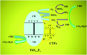 | ||
| Fig. 8 Schematic showing the mechanism for carbamazepine (CBZ) photocatalytic degradation on a TiO2−XFX/CTFs heterojunction. CB and VB are the conduction band and valence band, respectively. | ||
As is shown in Fig. 8, the conduction band of CTFs (0.2 eV)54 is more positive than TiO2−XFX (−0.5 eV),1 whereas the valence band of CTFs (1.48–1.83 eV) is more negative than TiO2−XFX (2.63 eV). Therefore, the photogenerated electrons and holes could transfer easily from the surface of TiO2−XFX to the surface of CTFs. In this case, the migration of e− and h+ between the two photocatalysts could effectively separate photo-charged carriers and further favour visible light absorption.
Conclusions
In summary, TiO2−XFX/CTFs van der Waals heterojunction photocatalysts were successfully synthesised using a stirring and sonication method. A synergetic effect of heterostructure catalysts was observed through the photocatalytic degradation of CBZ. The removal efficiency of CBZ was influenced by the TiO2−XFX/CTFs weight ratio and reaction time. The XPS results suggested a strong interaction between TiO2−XFX and CTFs and electron transfer between the two photocatalysts. The synergistic effect results in a smaller bandgap, improved light adsorption, and the separation of electrons and holes. In addition, CBZ adsorption under dark conditions was enhanced compared to TiO2−XFX owing to the increased number of active sites, which could be observed using FTIR and XPS. Furthermore, this highly efficient, low toxic, cheap, and high performing photocatalyst provides a novel, green, and facile method for organic pollutant treatment.Conflicts of interest
There are no conflicts to declare.Acknowledgements
This study was sponsored by the 68th Financial Grant from China Postdoctoral Science Foundation (no. 2020M681809), Preferential Funding Projects for Postdoctoral Scientific Research in Zhejiang Province (no. ZJ2020083) and K. C. Wong Magna Fund in Ningbo University.References
- Z. Q. He, J. T. Tang, J. Shen, J. M. Chen and S. Song, Appl. Surf. Sci., 2016, 364, 416–427 CrossRef CAS
.
- M. Pelaez, N. T. Nolan, S. C. Pillai, M. K. Seery, P. Falaras, A. G. Kontos, P. S. M. Dunlop, J. W. J. Hamilton, J. A. Byrne and K. O'Shea, Appl. Catal., B, 2012, 125, 331–349 CrossRef CAS
.
- C. H. Ao, S. C. Lee, Y. Z. Yu and J. H. Xu, Appl. Catal., B, 2004, 54, 41–50 CrossRef CAS
.
- A. Fujishima, T. N. Rao and D. A. Tryk, J. Photochem. Photobiol., C, 2000, 1, 1–21 CrossRef CAS
.
- I. J. Ochuma, R. P. Fishwick, J. Wood and J. M. Winterbottom, J. Hazard. Mater., 2007, 144, 627–633 CrossRef CAS
.
- A. C. Rodrigues, M. Boroski, N. S. Shimada, J. C. Garcia, J. Nozaki and N. Hioka, J. Photochem. Photobiol., A, 2008, 194, 1–10 CrossRef CAS
.
- A. Strini, S. Cassese and L. Schiavi, Appl. Catal., B, 2005, 61, 90–97 CrossRef CAS
.
- T. L. Thompson and J. T. Yates, Chem. Rev., 2006, 106, 4428–4453 CrossRef CAS
.
- B. Tahir, M. Tahir and N. S. Amin, Appl. Surf. Sci., 2015, 338, 1–14 CrossRef CAS
.
- W. Choi, A. Termin and M. R. Hoffmann, J. Phys. Chem., 1994, 98, 13669–13679 CrossRef
.
- J. Choi, H. Park and M. R. Hoffmann, J. Phys. Chem. C, 2009, 114, 78–792 Search PubMed
.
- X. Chen and C. Burda, J. Am. Chem. Soc., 2008, 130, 5018–5019 CrossRef CAS
.
- C. Wang, Q. Q. Hu, J. Q. Huang, C. Zhu, Z. H. Deng, H. L. Shi, L. Wu, Z. G. Liu and Y. G. Cao, Appl. Surf. Sci., 2014, 292, 161–164 CrossRef CAS
.
- M. M. Gui, S. P. Chai and A. R. Mohamed, Appl. Surf. Sci., 2014, 319, 37–43 CrossRef CAS
.
- K. Wojtaszek, A. Wach, J. Czapla-Masztafiak, K. Tyrala, J. Sa, L. Yıldız Ozer, C. Garlisi, G. Palmisanod and J. Szlachetko, Synchrotron Radiat., 2019, 26, 145–151 CrossRef CAS
.
- W. Choi, A. Termin and M. R. Hoffmann, J. Phys. Chem., 1994, 98, 13669 CrossRef
.
- A. L. Linsebigler, G. Q. Lu and J. T. Yates, Chem. Rev., 1995, 95, 735 CrossRef CAS
.
- W. Choi, A. Termin and M. R. Hoffman, J. Phys. Chem., 1994, 98, 13669 CrossRef
.
- Q. Zuo, T. Liu, C. Chen, Y. Ji, X. Gong, Y. Mai and Y. Zhou, Angew. Chem., Int. Ed., 2019, 58, 10198–10203 CrossRef CAS
.
- G. Lan, Y. Quan, M. Wang, G. T. Nash, E. You, Y. Song, S. S. Veroneau, X. Jiang and W. Lin, J. Am. Chem. Soc., 2019, 141, 15767–15772 CrossRef CAS
.
- I. Gadwal, G. Sheng, R. L. Thankamony, Y. Liu, H. Li and Z. Lai, ACS Appl. Mater. Interfaces, 2018, 10, 12295–12299 CrossRef CAS
.
- Y. Peng, Y. Huang, Y. Zhu, B. Chen, L. Wang, Z. Lai, Z. Zhang, M. Zhao, C. Tan, N. Yang, F. Shao, Y. Han and H. Zhang, J. Am. Chem. Soc., 2017, 139, 8698–8704 CrossRef CAS
.
- Y. Ying, D. Liu, J. Ma, M. Tong, W. Zhang, H. Huang, Q. Yang and C. Zhong, J. Mater. Chem. A, 2016, 4, 13444–13449 RSC
.
- K. Wang, Y. Tang, Q. Jiang, Y. Lan, H. Huang, D. Liu and C. Zhong, J. Energy Chem., 2017, 26, 902–908 CrossRef
.
- X. Jiang, P. Wang and J. J. Zhao, J. Mater. Chem. A, 2015, 15, 7750–7758 RSC
.
- K. K. Wang, H. L. Huang, D. H. Liu, C. Wang, J. P. Li and C. L. Zhong, Environ. Sci. Technol., 2016, 50, 4869–4876 CrossRef CAS
.
- K. Wang, L. M. Yang, X. Wang, L. Guo, G. Cheng, C. Zhang, S. Jin, B. Tan and A. Cooper, Angew. Chem., Int. Ed., 2017, 56, 14149–14153 CrossRef CAS
.
- M. Liu, Q. Huang, S. Wang, Z. Li, B. Li, S. Jin and B. Tan, Angew. Chem., Int. Ed., 2018, 57, 11968–11972 CrossRef CAS
.
- M. Liu, K. Jiang, X. Ding, S. Wang, C. Zhang, J. Liu, Z. Zhan, G. Cheng, B. Li, H. Chen, S. Jin and B. Tan, Adv. Mater., 2019, 31, 1807865–1807872 CrossRef
.
- P. Pachfule, A. Acharjya, J. Roeser, T. Langenhahn, M. Schwarze, R. Schomacker, A. Thomas and J. Schmidt, J. Am. Chem. Soc., 2018, 140, 1423–1427 CrossRef CAS
.
- Z. A. Lan, Y. X. Fang, Y. F. Zhang and X. C. Wang, Angew. Chem., Int. Ed., 2018, 57, 470–474 CrossRef CAS
.
- W. Huang, Z. J. Wang, B. C. Ma, S. Ghasimi, D. Gehrig, F. Laquai, K. Landfester and K. A. I. Zhang, J. Mater. Chem. A, 2016, 4, 7555–7559 RSC
.
- J. H. Yang, D. G. Wang, H. X. Han and C. Li, Acc. Chem. Res., 2013, 46, 1900–1909 CrossRef CAS
.
- F. Y. Wen and C. Li, Acc. Chem. Res., 2013, 46, 2355–2364 CrossRef CAS
.
- K. Wenderich and G. Mul, Chem. Rev., 2016, 116, 14587–14619 CrossRef CAS
.
- T. D. Nguyen, Q. T. P. Bui, T. B. Le, T. M. Altahtamouni, K. B. Vu, D. V. N. Vo, N. T. H. Le, T. D. Luu, S. S. Hong and K. T. Lim, RSC Adv., 2019, 9, 23526–23534 RSC
.
- D. Gao, W. Liu, Y. Xu, P. Wang, J. Fan and H. Yu, Appl. Catal., B, 2020, 260, 118190 CrossRef CAS
.
- S. C. Sun, Y. C. Zhang, G. Q. Shen, Y. T. Wang, X. L. Liu, Z. W. Duan, L. Pan, X. W. Zhang and J. J. Zou, Appl. Catal.,
B, 2019, 243, 253–261 CrossRef CAS
.
- H. G. Yu, R. R. Yuan, D. D. Gao, Y. Xu and J. G. Yu, Chem. Eng. J., 2019, 375, 121934 CrossRef CAS
.
- M. H. Ai, J. W. Zhang, R. J. Gao, L. Pan, X. W. Zhang and J. J. Zou, Appl. Catal., B, 2019, 256, 117805 CrossRef CAS
.
- X. Xu, L. Lai, T. Zeng, Y. Yu, Z. Q. He, J. M. Chen and S. Song, J. Phys. Chem. C, 2018, 122, 18870–18879 CrossRef CAS
.
- B. N. Bao, X. H. Miao, X. D. Hu, Q. Z. Zhang, X. Y. Jie and X. Y. Zheng, Catalysts, 2017, 7, 117 CrossRef
.
- X. C. Wang, K. Maeda, A. Thomas, K. Takanabe, G. Xin, J. M. Carlsson, K. Domen and M. Antonietti, Nat. Mater., 2009, 8, 76–80 CrossRef CAS
.
- D. Kong, X. Y. Han, J. J. Xie, Q. S. Ruan, C. D. Windle, S. Gadipelli, K. Shen, Z. M. Bai, Z. X. Guo and J. W. Tang, ACS Catal., 2019, 9, 7697–7707 CrossRef CAS
.
- P. Katekomol, J. Roeser, M. Bojdys, J. Weber and A. Thomas, Chem. Mater., 2013, 25, 1542–1548 CrossRef CAS
.
- K. Schwinghammer, S. Hug, M. B. Mesch, J. Senker and B. V. Lotsch, Energy Environ. Sci., 2015, 8, 3345–3353 RSC
.
- K. Wang, H. Huang, D. Liu, C. Wang, J. Li and C. Zhong, Environ. Sci. Technol., 2016, 50, 4869–4876 CrossRef CAS
.
- H. Q. Sun, Y. Bai, Y. P. Cheng, W. Q. Jin and N. P. Xu, Ind. Eng. Chem. Res., 2006, 45, 4971–4976 CrossRef CAS
.
- J. Li, P. Liu, H. L. Huang, Y. Li, Y. Z. Tang, D. H. Mei and C. L. Zhong, ACS Sustainable Chem. Eng., 2020, 8, 5175–5183 CrossRef CAS
.
- Y. Zhu, M. Qiao, W. Peng, Y. Li, G. Zhang, F. Zhang, Y. Li and X. Fan, J. Mater. Chem. A, 2017, 5, 9272e8 Search PubMed
.
- N. Bao, Y. Li, Z. Wei, G. Yin and J. Niu, J. Phys. Chem. C, 2011, 115, 5708–5719 CrossRef CAS
.
- B. Qiu, Y. Zhou, Y. Ma, X. Yang, W. Sheng, M. Xing and J. Zhang, Sci. Rep., 2015, 5, 8591 CrossRef CAS
.
- X. Jiang, P. Wang and J. Zhao, J. Mater. Chem. A, 2015, 3, 7750–7758 RSC
.
- T. Zeng, S. Q. Li, Y. Shen, H. Y. Zhang, H. R. Feng, X. L. Zhang, L. X. Y. Li, Z. W. Cai and S. Song, Appl. Catal., B, 2019, 257, 117915 CrossRef CAS
.
| This journal is © The Royal Society of Chemistry 2021 |

