
 Open Access Article
 This Open Access Article is licensed under a Creative Commons Attribution-Non Commercial 3.0 Unported Licence
Optimal fluorescence and photosensitivity properties of dual-functional NaYb1−xF4:Tmx3+ nanoparticles for applications in imaging guided photodynamic therapy†
Zhang Jiayin a,
Wang Qiyu*b,
Liang Honga,
Song Guoli*a and
Zhang Zhiguo*c
a,
Wang Qiyu*b,
Liang Honga,
Song Guoli*a and
Zhang Zhiguo*c
aSchool of Technology, Harbin University, Harbin 150086, China. E-mail: SONGGL@aliyun.com
bSchool of Physics & Electronic Engineering, Harbin Normal University, Harbin 150025, China. E-mail: hsdwqy@126.com
cSchool of Instrumentation Science and Engineering, Harbin Institute of Technology, Harbin 150080, P. R. China. E-mail: zhangzhiguo@hit.edu.cn
First published on 4th January 2021
Abstract
The fluorescence and photosensitivity properties of NaYb1−xF4:Tmx3+ nanoparticles were optimized to develop noninvasive near-infrared fluorescence imaging-guided photodynamic therapy. The emission at 800 nm from Tm3+ presented an exponential increase with an increase in the Tm3+ doping concentration from 0 to 2%. The photosensitivity properties of NaYb1−xF4:Tmx3+ nanoparticles were also studied via the chemoprobe method, which used a reactive oxygen quencher, 1,3-diphenylisobenzofuran (DPBF). With the increase in the doping concentration of Tm3+, the generation rate of reactive oxygen species in NaYb1−xF4:Tmx3+ nanoparticles decreased linearly at a rate of 0.3. The doping concentration of Tm3+ had two opposite effects on the 800 nm emission and generation rates of reactive oxygen species. The competitive relationship was discussed and an optimal value for the Tm3+ doping concentration of approximately 1% was determined. At this concentration, the energy of the Yb3+ excited state can be fully utilized, and the fluorescence and photosensitivity properties are an effective combination.
Introduction
Photodynamic therapy (PDT), due to its highly specific selectivity and minimal invasiveness, has become an intriguing route for treating tumors.1–3 In typical PDT, the photosensitizer (PS) is excited by light and generates reactive oxygen species (ROS), killing tumor cells with minimal damage to surrounding tissues. PSs are key components in the implementation of effective PDT.4,5 Generally, traditional PSs need to be excited by visible light, which results in poor penetration depth in tissue, due to which their use is limited to the superficial treatment of tumors.6,7 A tissue is known to have a biological window in the near infrared light (NIR) region from 800 to 1100 nm, as the excitation light in this range exhibits weak scattering and absorption in the tissue, enabling deep penetration. Efforts have been invested to extend the excitation wavelengths of PSs to the NIR range. For instance, two-photon-excited PSs have been developed.8–10 Unfortunately, the absorption cross-section of two-photon-excited PSs is too small, necessitating the use of a high-energy pulse laser, which significantly exceeds safe limits for clinical applications. Upconversion nanoparticle (UCNP)-based PSs, which feature UCNP-loaded traditional PSs (NPs-PSs) to perform PDT, are proposed as alternative candidates. Specifically, UCNPs absorb NIR light and emit visible light to trigger traditional PSs to generate ROS.11–13 In the process, severe relaxation losses and low upconversion efficiencies lead to an impractically low ROS quantum yield. Recently, we proposed an NIR-excited inorganic PS, NaYbF4 NPs, that could achieve NIR-excited PDT with high efficiencies via a simple energy transfer method.14 In addition, NaYbF4 NPs serve as PSs directly without drug loading and release, making the therapeutic effect more controllable and stable. However, NaYbF4 NPs are difficult to guide to the positions of tumor due to the weak emission of Yb3+. Therefore, it is imperative to introduce a luminescence element to NaYbF4 NPs for achieving precise tumor localization and high-efficiency PDT.In this study, we design a novel nanocomposite NaYb1−xF4:Tmx3+ as the PS for application to imaging-guided PDT. The fluorescence characteristics and ROS generation were investigated in detail using NaYb1−xF4:Tmx3+ NPs. The energy distribution relationship between the 800 nm fluorescence intensity and ROS generation rate was obtained. Next, the energy distribution between imaging and PDT was adjusted by changing the Tm3+ doping concentration, and an optimal value for the Tm3+ doping concentration was determined at which fluorescence and photosensitivity properties combined effectively.
Results and discussion
To explain the energy transfer mechanism of NaYb1−xF4:Tmx3+ as a PS, the energy level diagrams of the Yb3+, Tm3+, and O2 systems are shown in Fig. 1. On the one hand, Yb3+ absorbs NIR excitation light, and passes on part of its energy to Tm3+ via two successive energy transfer processes to populate the 3F2,3 states of Tm3+. Next, the population in the 3F2,3 states relaxes to the 3H4 state via the nonradiative relaxation process. Moreover, the population in the 3H4 state decays radiatively to the ground state, resulting in the NIR emission band at approximately 800 nm.15 On the other hand, excited Yb3+ can directly transfer part of their energy to oxygen to generate ROS via a simple energy transfer process. Therefore, the NaYb1−xF4:Tmx3+ NPs are very suitable as PSs for imaging-guided PDT. | ||
| Fig. 1 Energy levels of Yb3+, Tm3+, and O2 systems and the proposed energy transition mechanisms for the 800 nm upconversion emission and generation of ROS. | ||
A typical TEM image and a low-magnification TEM image of NaYb99%F4:Tm1%3+ are shown in Fig. 2a and S1,† respectively. A histogram of the NP size distribution was obtained using the Nano Measurer 1.2.5 software by calculating the size of NPs in the TEM bright-field image (Fig. 2b). The mathematical details regarding the calculation of the particle size distribution are presented in Table S1.† The mean NP size is approximately 6.5 nm. The XRD pattern of NaYb99%F4:Tm1%3+ NPs was obtained, and the positions of the diffraction peaks were found to closely match the JCPDS-PDF 77-2043 cubic phase of NaYbF4 NPs (Fig. 2c). Furthermore, the effect of the Tm3+ doping concentration on the structure of NaYb1−xF4:Tmx3+ NPs was investigated through XRD analysis using specimens with Tm3+ concentrations of 1% and 2%, as shown in Fig. S2.† No distinct difference was observed between the diffraction angles for Tm3+ concentrations at 1% and 2%. It is probably due to similar radii of 0.0858 nm and 0.087 nm for Yb3+ and Tm3+, respectively. A low doping concentration would not cause a marked change in the crystal lattice. Liang et al. conducted a similar study. They found that when the Yb3+ concentration in NaYb98%F4:Tm2%3+ is approximately 98%, the XRD pattern is consistent with the JCPDS standard card.16
 | ||
| Fig. 2 (a) Typical TEM image of NaYb1−xF4:Tmx3+ (x = 1%) NPs; (b) size distribution of NaYb99%F4:Tm1%3+ NPs; (c) corresponding XRD pattern. | ||
Fig. 3a presents the fluorescence spectra of NaYb1−xF4:Tmx3+ (x = 1, 2, 3, 4) NPs. Further, the integrated intensities of the 800 nm emission with different Tm3+ doping concentrations are shown intuitively in Fig. 3b. The intensity of the 800 nm emission is observed to initially increase. When the doping concentration of Tm3+ reaches 2%, the fluorescence intensity of 800 nm is at its maximum. As the doping concentration of Tm3+ continues to increase, the fluorescence intensity at 800 nm begins to decrease due to Tm3+ concentration quenching. In this study, we consider the Tm3+ concentration to be within 2%. The detailed relationship between the fluorescence intensity and Tm3+ concentration is explored. The typical fluorescence spectra of NaYb1−xF4:Tmx3+ (x = 0.2, 0.5, 1, 1.5, 2) NPs are shown in Fig. 3c. Fig. 3d shows the 800 nm fluorescence intensities of NaYb1−xF4:Tmx3+ NPs at different Tm3+ concentrations. We used the average value and standard deviation of the 800 nm emission for three-repeats of measurement, as shown in Fig. S3,† which was normalized by the intensity for 2% Tm3+. The normalized 800 nm fluorescence intensities of NaYb1−xF4:Tmx3+ NPs were enhanced exponentially with the Tm3+ doping concentration (x) in the form of y = 1 − exp(−x/x0), which is shown in Fig. 3d. Although x0 = 0.6% is the optimized Tm3+ doping concentration for the fluorescence intensity, it is not the optimum concentration for dual functions (imaging and PDT).
 | ||
| Fig. 3 (a) 800 nm emission spectra of NaYb1−xF4:Tmx3+ (x = 1, 2, 3, 4%); (b) fluorescence intensity with Tm3+ concentration over a wide range; (c) 800 nm emission spectra of NaYb1−xF4:Tmx3+ (x = 0.2, 0.5, 1, 1.5, 2%); (d) relationship between fluorescence intensity and Tm3+ concentration for a narrow range. | ||
To theoretically investigate the effect of the Tm3+ concentration on the intensity of the 800 nm emission, the rate equations in the steady states based on the energy transitions were studied through eqn (S1)–(S5).† As illustrated in eqn (S5),† the same pump power density was utilized to excite the 800 nm emissions; hence, ρ is a constant parameter for all the samples. The absorption cross-sections of the Yb3+ ions are similar. NYb0 can be regarded as constant because the concentration of Yb3+ only exhibits a small change. Therefore, eqn (S5)† can be simplified as follows:
| I800 ∝ W0W1N0τYb12τ1 | (1) |
The intensity of the 800 nm emission in eqn (1) is related to: the energy transfer rate between Yb3+ and Tm3+ ions (Wi); the population densities of the ground state (N0) in Tm3+; and the decay times of Yb3+ in excited states (τYb1) and Tm3+ in 3F4 states (τ1). When the Tm3+ concentration increases, W0, W1, and N0 in eqn (1) increase. On the contrary, with increasing Tm3+ concentration, the distance between the Tm3+ ions decreases and cross-relaxation is enhanced, leading to a decrease in τYb1 and τ1.16–18 At low concentrations of Tm3+, the rates of increase for W0, W1, and N0 are higher than the rate of decrease for τYb12τ1; hence, the intensity of the 800 nm emission increases with increasing Tm3+ concentration. As the Tm3+ concentration continues to increase, the decrease in τYb12τ1 is faster than the increases in W0, W1, and N0. This is probably because the values of τYb1 and τ1 are very small and τYb12τ1 decreases rapidly due to the power function and product form. Therefore, the intensity of the 800 nm emission decreases at a high Tm3+ concentration.
Furthermore, we studied the relationship between singlet oxygen generation and the Tm3+ doping concentration. The 1,3-diphenylisobenzofuran (DPBF) absorbance spectra of NaYb1−xF4:Tmx3+ (x = 0.2, 0.5, 1, 1.5, 2%) were measured three times (Fig. S4†). Fig. 4a displays the normalized DPBF absorbance as a function of the irradiation time in the NaYb1−xF4:Tmx3+ NP solutions. The absorbance shows an exponential decay with the light exposure time. Next, the consumption rate of DPBF as an indicator of ROS generation rate was determined by the slope of linear fitting,19 as shown in the inset of Fig. 4a. Fig. 4b shows the consumption rates of DPBF at different Tm3+ concentrations, which use the average value and standard deviation for three-repeats of measurement and are normalized by the intensity of Tm3+ of 0.2%. At low Tm3+ concentrations (0.2–2%), the consumption rates of DPBF decrease linearly at a rate of 0.3 as the Tm3+ concentration increases.
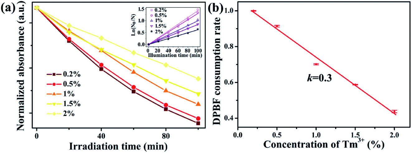 | ||
| Fig. 4 (a) DPBF absorbance at 410 nm versus exposure time and consumption rates of DPBF under different Tm3+ concentrations in NaYb1−xF4:Tmx3+ (x = 0.2, 0.5, 1, 1.5, 2%); (b) relationship between DPBF consumption rate and Tm3+ concentration in NaYb1−xF4:Tmx3+ (x = 0.2, 0.5, 1, 1.5, 2%). | ||
For the application of dual-functional NaYb1−xF4:Tmx3+ NPs, the energy competition mechanism between fluorescence and ROS generation from Yb3+ in the excited state should be considered. The Tm3+ doping concentration has opposite effects on the fluorescence and ROS generation (Fig. 5a). On the one hand, an increase in the Tm3+ doping concentration would facilitate a strong 800 nm upconversion emission. On the other hand, an increased Tm3+ doping concentration is unfavorable for a high ROS generation rate. Considering the two opposing effects, an optimum Tm3+ doping concentration is required to balance the energy distribution between fluorescence and ROS generation. Here, the variation rate (rate of decrease or increase) of ROS generation and fluorescence intensity can be employed to evaluate the relative rate of variations at different Tm3+ doping concentrations. The variation rate can be determined by the derivation of the curves in Fig. 5a. The variation rates of fluorescence intensity and ROS generation are shown in Fig. 5b. The decreasing rate of ROS-generating efficiency is 0.3, which is a constant. Furthermore, the rate of increase of fluorescence intensity decreases exponentially. When the Tm3+ doping concentration is less than 1%, the rate of increase for fluorescence intensity is greater than the rate of decrease for ROS generation. Therefore, the improvement in the fluorescence intensity is worth the loss of ROS generation. However, when the Tm3+ concentration exceeds 1%, the increasing rate of fluorescence intensity is less than the decreasing rate of ROS generation. Hence, there is an optimal value for the Tm3+ concentration, which corresponds to approximately 1%. At this concentration, the energy of the Yb3+ excited state can be fully utilized, allowing for the most efficient manner of energy distribution.
 | ||
| Fig. 5 (a) Fluorescence intensity and DPBF consumption rate with Tm3+ concentration in NaYb1−xF4:Tmx3+ (x = 0.2, 0.5, 1, 1.5, 2%); (b) variation rate of fluorescence intensity and DPBF consumption rate at different Tm3+ concentrations in NaYb1−xF4:Tmx3+ (x = 0.2, 0.5, 1, 1.5, 2%). | ||
Experimental
Synthesis of NPs
NaYb1−xF4:Tmx3+ (x = 0.2, 0.5, 1, 1.5, 2%, 3%, 4%) was synthesized by a previously reported method.20 A mixture comprising 1 mmol LnCl3·H2O (YbCl3·H2O and TmCl3·H2O), 6 mL oleic acid, and 15 mL 1-octadecene was loaded into a 50 mL round bottom flask. The mixture was stirred vigorously for 1 h at 160 °C to produce a clear solution with N2 as the shielding gas. Then the solution was cooled down to 50 °C and a 10 mL methanol solution with NaOH (0.1 g) and NH4F (0.148 g) was added, which was stirred for 30 min. The methanol and water in the mixture solution were evaporated at 100 °C with a strong stream of nitrogen to avoid oleic acid oxidized. The solution was heated to 300 °C and kept 60 min with constant stirring. Finally, the mixture was cooled down to room temperature and precipitated by ethanol. The synthesized NaYb1−xF4:Tmx3+ NPs were washed three times with a mixture of ethanol and cyclohexane to remove impurities. The NPs were then collected by centrifugation. After purification, the NPs were stored in cyclohexane.The generation rate of ROS
The generation rate of reactive oxygen species can be evaluated by consumption rate of DPBF. The time-dependent concentration of DPBF during ROS generation can be described as follows:21
 | (2) |
Eqn (2) can be rewritten as:
 | (3) |
Then, the consumption rate of DPBF (k) can be given by the slope of the eqn (3).
For the concentrations of DPBF, we employ the Beer–Lambert law to calculate. The transmission intensity can be described as:
It = I0![[thin space (1/6-em)]](https://www.rsc.org/images/entities/char_2009.gif) exp(σ[DPBF]L), exp(σ[DPBF]L),
| (4) |
| A = ln(I0/It) | (5) |
Absorption spectra measurement
DPBF solution (0.02 μmol mL−1) with NaYb1−xF4:Tmx3+ (12 μmol mL−1) was exposed to a 980 nm laser with the power of 1.5 W. The transmission spectra of DPBF in the solutions were measured every 20 minutes. A deuterium lamp served as the light source of transmission spectra, and a miniature QE65000 fiber optic spectrometer (Ocean Optics, USA) was used to detect the transmission from UV to visible light. The absorption spectrum of DPBF can be obtained according to the Beer–Lambert law.Characterization method
X-ray diffraction (XRD) was obtained using Rigaku D/MAX-2600/PC with the Cu Kα radiation (λ = 1.5406 Å) at the scanning step at 0.02°. Transmission electron microscope (TEM) image was obtained using FEI Tecnai TF20.Fluorescence spectra measurement
The fluorescence spectra were measured at room temperature using 70 mW power-controlled 980 nm laser diode as an excitation source. A monochromator (Zolix Instrument SBP 300) coupled with photomultiplier (Zolix Instrument PMTH-S1-CR131) was used to collect the 800 nm upconversion fluorescence. The scanning step is 1 nm. All fluorescence spectra were measured using the same measuring system under the same conditions.Conclusions
The ROS generation and 800 nm emission in NaYb1−xF4:Tmx3+ NPs were investigated for application in imaging-guided PDT. The Tm3+ doping concentration was found to have opposite effects on the ROS generation and 800 nm emission. At low Tm3+ concentrations, the increasing rate of ROS generation exceeded the decreasing rate of fluorescence intensity. Additionally, the former was slower than the latter. When the Tm3+ concentration reached 1%, the variation rate of ROS generation and fluorescence intensity was equal. At this concentration, the energy of Yb3+ in the excited state could be used efficiently and the combination effect of fluorescence imaging and PDT was optimum.Conflicts of interest
There are no conflicts to declare.Acknowledgements
This work was supported by the National Natural Science Foundation of China (no. 81571720 and 81530052), Natural Science Foundation of Heilongjiang Province (No. LH2019A028), the 13th Five-year Educational Science Planned Projects in Heilongjiang Province (No. GJB1319071).References
- A. V. Kachynski, A. Pliss, A. N. Kuzmin, T. Y. Ohulchanskyy, A. Baev, J. Qu and P. N. Prasad, Nat. Photonics, 2014, 8, 455 CrossRef CAS.
- Fujin Ai, N. Wang, X. M. Zhang, T. Y. Sun, Q. Zhu, W. Kong, F. Wang and G. Y. Zhu, Nanoscale, 2018, 10, 4432 RSC.
- H. M. Chen, G. D. Wang, Y. J. Chuang, Z. P. Zhen, X. Y. Chen, P. Biddinger, Z. L. Hao, F. Liu, B. Z. Shen, Z. W. Pan and J. Xie, Nano Lett., 2015, 15, 2249 CrossRef CAS.
- Y. K. Wang, D. D. Cai, H. X. Wu, Y. Fu, Y. Cao, Y. J. Zhang, D. M. Wu, Q. W. Tian and S. P. Yang, Nanoscale, 2018, 10, 4452 RSC.
- M. Ochsner, J. Photochem. Photobiol., B, 1997, 39, 1 CrossRef CAS.
- T. J. Dougherty, C. J. Gomer, B. W. Henderson, G. Jori, D. Kessel, M. Korbelik, J. Moan and Q. Peng, J. Natl. Cancer Inst., 1998, 90, 889 CrossRef CAS.
- M. Ethirajan, Y. H. Chen, P. Joshi and R. K. Pandey, Chem. Soc. Rev., 2011, 40, 340 RSC.
- E. D. Sternberg, D. Dolphin and C. Bruckner, Tetrahedron, 1998, 54, 4151 CrossRef CAS.
- M. Pawlicki, H. A. Collins, R. G. Denning and H. L. Anderson, Angew. Chem., Int. Ed., 2009, 48, 3244 CrossRef CAS.
- H. A. Collins, M. Khurana, E. H. Moriyama, A. Mariampillai, E. Dahlstedt, M. Balaz, M. K. Kuimova, M. Drobizhev, V. X. D. Yang, D. Phillips, A. Rebane, B. C. Wilson and H. L. Anderson, Nat. Photonics, 2008, 2, 420 CrossRef CAS.
- B. M. Velusamy, J. Y. Shen, J. T. Lin, Y. C. Lin, C. C. Hsieh, C. H. Lai, C. W. Lai, M. L. Ho, Y. C. Chen, P. T. Chou and J. K. Hsiao, Adv. Funct. Mater., 2009, 19, 2388 CrossRef.
- X. Liu, M. Zheng, X. Kong, Y. Zhang, Q. Zeng, Z. Sun, W. Buma and H. Zhang, Chem. Commun., 2013, 49, 3224 RSC.
- S. Y. Liu, Y. Yuan, Y. K. Yang, Z. H. Liu, S. Y. Yin, W. P. Qin and C. F. Wu, J. Mater. Chem. B, 2017, 5, 8169 RSC.
- P. Zhang, W. Steelant, M. Kumar and M. Scholfield, J. Am. Chem. Soc., 2007, 129, 4526 CrossRef CAS.
- J. Y. Zhang, S. Chen, P. Wang, D. J. Jiang, D. X. Ban, N. Z. Zhong, G. C. Jiang, H. Li, Z. Hu, J. R. Xiao, Z. G. Zhang and W. W. Cao, Nanoscale, 2017, 9, 2706 RSC.
- J. Y. Zhang, H. Zhao, X. T. Zhang, X. Z. Wang, H. Gao, Z. G. Zhang and W. W. Cao, J. Phys. Chem. C, 2014, 118, 2820 CrossRef CAS.
- H. J. Liang, Y. D. Zheng, L. Wu, L. X. Liu, Z. G. Zhang and W. W. Cao, J. Lumin., 2011, 131, 1802 CrossRef CAS.
- C. Z. Zhao, X. G. Kong, S. G. Song and X. K. Li, Chin. J. Lumin., 2013, 34, 959 CrossRef CAS.
- Y. Wang, K. Liu, X. M. Liu, K. Dohnalova, T. Gregorkiewicz, X. G. Kong, M. C. G. Aalders, W. J. Buma and H. Zhang, J. Phys. Chem. Lett., 2011, 2, 2083 CrossRef CAS.
- Z. Q. Li and Y. Zhang, Nanotechnology, 2008, 19, 345606 CrossRef.
- F. Wilkinson, W. P. Helman and A. B. Ross, J. Phys. Chem. Ref. Data, 1993, 22, 113 CrossRef CAS.
Footnote |
| † Electronic supplementary information (ESI) available. See DOI: 10.1039/d0ra09544c |
| This journal is © The Royal Society of Chemistry 2021 |