
 Open Access Article
 This Open Access Article is licensed under a Creative Commons Attribution-Non Commercial 3.0 Unported Licence
Marigold micro-flower like NiCo2O4 grown on flexible stainless-steel mesh as an electrode for supercapacitors
Gokul P. Kamblea,
Anil A. Kashalea,
Akash S. Rasalab,
Seema A. Manea,
Rutuja A. Chavana,
Jia-Yaw Chang b,
Yong-Chien Ling*c,
Sanjay S. Kolekard and
Anil V. Ghule*a
b,
Yong-Chien Ling*c,
Sanjay S. Kolekard and
Anil V. Ghule*a
aGreen Nanotechnology Laboratory, Department of Chemistry, Shivaji University, Kolhapur 416004, Maharashtra, India. E-mail: avg_chem@unishivaji.ac.in
bDepartment of Chemical Engineering, National Taiwan University of Science and Technology, Taipei, Taiwan
cDepartment of Chemistry, National Tsing Hua University, Hsinchu 30013, Taiwan. E-mail: ycling@mx.nthu.edu.tw
dAnalytical Chemistry and Material Science Research Laboratory, Department of Chemistry, Shivaji University, Kolhapur 416004, Maharashtra, India
First published on 18th January 2021
Abstract
Nanostructured NiCo2O4 is a promising material for energy storage systems. Herein, we report the binder-free deposition of porous marigold micro-flower like NiCo2O4 (PNCO) on the flexible stainless-steel mesh (FSSM) as (PNCO@FSSM) electrode by simple chemical bath deposition. The SEM and EDS analysis revealed the marigold micro-flowers like morphology of NiCo2O4 and its elemental composition. The porous nature of the electrode is supported by the BET surface area (100.47 m2 g−1) and BJH pore size diameter (∼1.8 nm) analysis. This PNCO@FSSM electrode demonstrated a specific capacitance of 530 F g−1 at a high current density of 6 mA cm−2 and revealed 90.5% retention of specific capacitance after 3000 cycles. The asymmetric supercapacitor device NiCo2O4//rGO within a voltage window of 1.4 V delivered a maximum energy density of 41.66 W h kg−1 at a power density of 3000 W kg−1. The cyclic stability study of this device revealed 73.33% capacitance retention after 2000 cycles. These results indicate that the porous NiCo2O4 micro-flowers electrode is a promising functional material for the energy storage device.
1. Introduction
In recent years, the ever-increasing demand for energy, rapidly depleting natural resources, and increasing environmental pollution concerns related to the use of conventional energy resources have compelled the scientific community to probe for clean and renewable energy sources.1–3 This facilitated the exploration and use of renewable resources for complimenting the energy demand. However, the intermittent renewable energy sources have posed a big challenge to the scientific society to develop efficient technology for its harvesting and storage enabling its use when required. This urged the development of efficient energy storage systems.Supercapacitors have been considered as promising energy conversion and storage devices because of their environmental friendliness, fast charge–discharge rate, high power density, long cycling life, low-cost and diverse configurations.4–6 Based on the charge storage mechanism, the supercapacitor can be classified into two types; (i) electric double-layer capacitor (EDLC), utilizing the electrostatic charge separation at the electrode/electrolyte interface and developing potential due to formation of the electric double layer at the interface of electrode/electrolyte, (ii) redox or pseudocapacitor store energy by either an adsorption/desorption process or reversible redox reaction occurring on the surface of active material.7–9 On the other hand, transition metal oxides (TMOs) as electrode materials have been widely explored because of their high theoretical specific capacitances, abundance, high voltage window in aqueous electrolyte, environmental friendliness, and low-cost of electrode material for pseudocapacitors.10–14 Unfortunately, most TMOs suffer from their weak electrical conductivities resulting in poor electrochemical performance.15,16 To circumvent this issue, researchers developed mixed TMOs with different metal cations demonstrating the synergic effect, reversible capacity, structural stability, more active reaction sites for redox (faradaic) reaction, and higher electrical conductivity compared to TMOs.17 Among the mixed TMOs, metal cobaltite (MCo2O4, wherein M refers to multivalent metal) based electrodes with spinel structure are the most studied candidates in supercapacitor due to its excellent redox behavior.18,19 Particularly, NiCo2O4 has proved to be a promising cobaltite material because adding nickel not only improves the conductivity of cobaltite but also, enhances theoretical capacity and electrochemical activity.8,20,21 The improvement in the electrochemical performance of the electrode material is mostly concerned with the rational design of crystal structure and morphology. Thus, NiCo2O4 with diverse morphologies such as nanosheet,22 nanoneedle,23 nanowire,24 nanosphere,25 nanorod,26 nanoflower,27 nanofiber28 have been explored and synthesized by different methods like hydrothermal,29,30 chemical vapor deposition (CVD),31 sputtering,32 chemical bath deposition (CBD),33 screen printing,34 solvothermal,35 electrodeposition36 and spray pyrolysis.37 However, most of these methods are multi-step, time-consuming, and complex which increases the cost of supercapacitor device fabrication.
Furthermore, the porosity of electrode material plays an important role in improving the electrochemical performance of supercapacitors as it results in increasing the surface area and consequently provides more active sites for charge storage.38,39 In addition to this, binder-free deposition of the thin-film electrode is important as the polymer binders are known to reduce the number of active sites and electrochemical performance. Hence, researchers are interested in developing thin films of the electrode material without the aid of the polymer binder.
With this motivation, herewith we are reporting binder-free growth of marigold micro flower-like porous NiCo2O4 electrode on flexible stainless-steel mesh (PNCO@FSSM) using simple chemical bath deposition at room temperature for its application in supercapacitor. This PNCO@FSSM electrode exhibited appreciably high specific capacitance of 530 F g−1 at a high current density of 6 mA cm−2 with 90.5% capacity retention after 3000 cycles in a 6 M KOH electrolyte. An asymmetric supercapacitor device fabricated using marigold-like PNCO@FSSM as the positive electrode and reduced graphene oxide (rGO) as the negative electrode with an operating potential window of 1.4 V delivered a maximum energy density of 41.66 W h kg−1 at a power density of 3000 W kg−1. Moreover, the device demonstrates excellent cyclic stability with 73.33% capacitance retention after 2000 cycles.
2. Experimental
2.1 Materials
Nickel chloride hexahydrate (NiCl2·6H2O), cobalt nitrate hexahydrate (Co(NO3)2·6H2O), oxalic acid dihydrate (H2C2O4·2H2O), acetylene black (AB), reduced graphene oxide (rGO), polyvinyl alcohol (PVA), polyvinylidene fluoride (PVDF), N-methyl pyrrolidone (NMP), cellulose paper were purchased from Sigma-Aldrich Ltd. All the chemicals were used as received without further purification. The deposition of thin films was carried out on the flexible stainless steel 300 mesh (FSSM-300) procured from Micromesh India Pvt. Ltd. Double distilled water (DDW) was used for preparing the solutions.2.2 Synthesis of PNCO@FSSM
The chemical bath deposition method was employed for the synthesis of the PNCO@FSSM electrode. A piece of FSSM (length × width = 1 cm × 1 cm) was cleaned ultrasonically with soap solution and water. 50 mmol of H2C2O4·2H2O was dissolved in 100 mL DDW followed by the addition of a 50 mL aqueous solution of 2 mmol of NiCl2·6H2O and 4 mmol of Co(NO3)2·6H2O at 25 °C (room temperature) with magnetic stirring to form a clear solution. The precleaned FSSM substrate was vertically fixed into the aqueous solution of oxalic acid and the solution was stirred for 5 min. After the addition of an aqueous solution of NiCl2 and Co(NO3)2 into the oxalic acid solution, the resultant mixture was stirred for 30 min. The corresponding complex formed on the FSSM in the form of thin-film was annealed at 350 °C for 2 h to form the PNCO@FSSM electrode.2.3 Materials characterization
X-ray diffraction (XRD) pattern of the NiCo2O4 micro-flowers was recorded at a scan rate of 1° min−1 in the 2-theta range from 10° to 80° using Bruker, D2-Phaser X-ray diffractometer with CuKα1 (1.5406 Å) radiation as an X-ray source. Fourier transform infrared (FTIR) spectrum was recorded in the range from 480 to 4000 cm−1 by using Bruker Alfa Spectrometer. A small portion of the sample was mixed with KBr to form a pellet and used for the analysis. X-ray photoelectron spectroscopy (XPS) analysis was carried out using the VG Multilab ESCA 2000 system (USA), using a monochromatic Mg Kα source (1.254 keV). The elemental composition and proportionate distribution of Ni, Co, and O were studied with energy dispersive spectroscopy (EDS) (Oxford Instruments). The morphology of the thin film was investigated by recording scanning electron microscopy (SEM) (Mira3, TESCAN) images. The specific surface area and pore size distributions of the NiCo2O4 were evaluated by Brunauer–Emmett–Teller (BET) (NOVA1000e Quantachrome, USA).2.4 Electrochemical measurements
The CHI 608E electrochemical analyzer was used for the electrochemical experiments, which were carried out at room temperature in 6 M KOH aqueous electrolyte unless otherwise mentioned. Cyclic voltammetry (CV), galvanostatic charge–discharge (GCD), and electrochemical impedance spectroscopy (EIS) were carried out in a standard three-electrode system with graphite and a saturated Ag/AgCl electrode as the counter and reference electrodes, respectively. The specific capacitance (Csp, F g−1), the energy density (E, W h kg−1), and power density (P, kW kg−1) were calculated according to the following equations:40,41| Csp = I × Δt/m × ΔV | (1) |
| E = Csp × ΔV2/7.2 | (2) |
| P = 3.6 × E/Δt | (3) |
2.5 PNCO@FSSM//rGO assembly and measurements
The PNCO@FSSM electrode is used as a positive and the rGO@FSSM as a negative electrode in the PVA/KOH electrolyte for the assembly of the NiCo2O4//rGO asymmetric supercapacitor device. Two electrodes were separated by a piece of cellulose paper (separator sandwiched between two electrodes). The rGO was selected because it is an economic alternative and also has high conductivity.42 rGO, AB, and PVDF with 80![[thin space (1/6-em)]](https://www.rsc.org/images/entities/char_2009.gif) :10:10 weight ratio were added in the NMP solvent to form the slurry, which was then uniformly pasted on the substrate. The prepared negative electrode was dried in the oven at 90 °C for 8 h. 5 g PVA and 4 g KOH in 80 mL of DDW was used for preparing the PVA-KOH electrolyte. The positive and negative electrode and the cellulose separator was soaked in the PVA/KOH electrolyte at 25 °C for 4 h. To ensure good contact of electrode material and the electrolyte. The electrodes were then taken out and assembled into a NiCo2O4//rGO asymmetric supercapacitor and then pressed at 6 MPa.
:10:10 weight ratio were added in the NMP solvent to form the slurry, which was then uniformly pasted on the substrate. The prepared negative electrode was dried in the oven at 90 °C for 8 h. 5 g PVA and 4 g KOH in 80 mL of DDW was used for preparing the PVA-KOH electrolyte. The positive and negative electrode and the cellulose separator was soaked in the PVA/KOH electrolyte at 25 °C for 4 h. To ensure good contact of electrode material and the electrolyte. The electrodes were then taken out and assembled into a NiCo2O4//rGO asymmetric supercapacitor and then pressed at 6 MPa.
3. Results and discussion
The phase purity and crystallinity of the synthesized NiCo2O4 was analyzed by the X-ray diffraction technique. Fig. 1a shows the representative XRD patterns of the synthesized NiCo2O4 micro-flower sample in comparison with JCPDS: 20-0781. The diffraction peaks of the NiCo2O4 sample were indexed to the typical spinel structure of NiCo2O4 (JCPDS No. 20-0781). The characteristic peaks located at 2θ = 18.8°, 31.2°, 36.5°, 44.3°, 55.2°, 59.0°, 64.5°, and 77.2° corresponds to (1 1 1), (2 2 0), (3 1 1), (4 0 0), (4 2 2), (5 1 1), (4 4 0) and (5 3 3) plane of cubic NiCo2O4, respectively. No other impurity peaks were noted in the spectrum indicates the complete conversion of precursor into NiCo2O4 after annealing. The broad diffraction peaks indicate the poor crystalline nature of the NiCo2O4 micro-flower array.43 | ||
| Fig. 1 (a) Representative XRD spectrum and (b) FTIR spectrum of synthesized NiCo2O4. | ||
The FTIR spectrum of NiCo2O4 was recorded as shown in Fig. 1b to confirm the conversion of reactants forming the metal oxide. The FTIR spectrum reveals the presence of peaks at 557 and 648 cm−1 which is characteristic of M–O vibrational frequency at tetrahedral and octahedral sites in metal oxide, respectively. In this work, cobalt nitrate salt was used as a precursor and the absence of N–O stretching vibrations at 1047 cm−1 (characteristic peak of the –NO3 group) indicates that the reactant was converted into the product.44 The peaks at 1635 and 1384 cm−1 which are characteristic of bending and stretching vibrations of the carbonyl group (O![[double bond, length as m-dash]](https://www.rsc.org/images/entities/char_e001.gif) C) were noted in the spectra, which are likely from the adsorbed atmospheric CO2 or traces of intermediate oxalates remains in the synthesis process. A broad peak observed at around 3412 cm−1 is attributed to –OH of chemisorbed water.
C) were noted in the spectra, which are likely from the adsorbed atmospheric CO2 or traces of intermediate oxalates remains in the synthesis process. A broad peak observed at around 3412 cm−1 is attributed to –OH of chemisorbed water.
Fig. 2a shows an SEM image revealing marigold flower-like morphology of NiCo2O4 with a diameter of 5 μm size. The magnified SEM image of NiCo2O4 micro-flowers reveals well-resolved nano-petals as observed in Fig. 2b. It demonstrates that the NiCo2O4 micro-flowers are composed of numerous thin and long nano-petals grown vertically outward from the centre forming an open porous network structure. Each nano-petals is vertically aligned with the height and thickness of petals being 1 μm and 40 nm, respectively. It is presumed that the open porous network structure would provide abundant surface area and active sites on the electrode for the electrolyte, which is essential for improving the electrochemical performance. Further, EDS analysis is performed to determine the chemical composition of the synthesized NiCo2O4 which shows the presence of Ni, Co, and O elements. The obtained atomic percentage ratio of Ni and Co is found to be 1:2 and is in good agreement with the calculated and expected stoichiometric ratio (Fig. 2c). The slight variation observed in the composition was within the range of standard compositions. The photograph of a marigold flower is presented in Fig. 2d for better comparison.
 | ||
| Fig. 2 (a) Low magnification SEM images of the NiCo2O4, (b) high magnification SEM image and (c) EDS spectrum of NiCo2O4, and (d) photograph of the marigold flower. | ||
N2 adsorption/desorption study was performed to investigate the Brunauer–Emmett–Teller (BET) surface area and the Barrett–Joyner–Halenda (BJH) pore size distributions of PNCO materials (Fig. 3). The adsorption at P/P0 approaches 0.95 indicates the porous nature of NiCo2O4 and its specific surface area is noted to be 144.9 m2 g−1. The graph indicates type IV isotherms with hysteresis loop at relative pressure between 0.4 and 0.95 supporting mesoporous nature according to IUPAC classification. The BJH pore size distribution curve (inset in Fig. 3) shows narrow pore size distribution with an average pore diameter of ∼1.8 nm supporting microporous nature.45,46 Thus, the PNCO@FSSM exhibits a larger specific surface area due to the porosity of the material, which is beneficial to accumulate a large number of ions of electrolyte during the electrochemical reaction. Furthermore, it is expected to reduce the path length facilitating ions diffusion and transport of ions and electrons, thereby enhancing the electrochemical performance.47
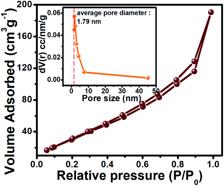 | ||
| Fig. 3 Adsorption isotherm plots obtained from NiCo2O4. Inset shows the pore size distribution plot. | ||
The elemental composition of the NiCo2O4 sample and their oxidation states were studied using XPS. Fig. 4 represents the survey spectrum of the PNCO sample. The survey spectrum confirms the presence of Ni, Co, and O including the adventitious copies of C in the sample. The high-resolution XPS spectra of Ni 2p, Co 2p, and O 1s are shown as insets in Fig. 4. The deconvoluted Ni 2p spectrum reveals two spin–orbit doublets corresponding to Ni2+ and Ni3+ and two shakeup satellite peaks marked as “Sat”. The peaks at 856.7 and 874.2 eV are attributed to the +2 oxidation state of Ni, while the peaks at 855.1 and 873.2 eV corresponds to the +3 oxidation state of Ni. The satellite peaks at binding energy 862.4 (Ni 2p3/2) and 880.5 eV (Ni 2p1/2) are shakeup satellite peaks.48 On the other hand, the high-resolution spectrum of the cobalt show two peaks located at 781.1 and 796.4 eV which are attributed to Co 2p3/2 and Co 2p1/2, respectively. The deconvoluted peaks at 780.6 and 796.0 eV corresponds to the +3 oxidation state of Co whereas, the peaks at 782.1 and 797.6 eV are attributed to the +2 oxidation state of Co. In addition to this, the two satellite peaks at 788.4 and 803.8 eV were observed in the spectrum of Co 2p supporting the existence of cobalt in Co2+ and Co3+ oxidation state.27 High-resolution spectra of oxygen (O 1s) shown as an inset in Fig. 4 revealed a broad peak which on deconvolution was resolved into two peaks with binding energy 530.1 and 531.9 eV which could be attributed to the metal–oxygen and surface (–OH) hydroxyl groups, respectively.49,50
 | ||
| Fig. 4 Representative XPS survey spectrum of the NiCo2O4. The insets show Ni 2p, Co 2p, and O 1s spectra. | ||
The electrochemical performance of the PNCO@FSSM electrode was investigated using 6 M KOH as the electrolyte. Considering the ionic radii of K+ and OH− ions in the electrolyte and the porous nature of PNCO, the mobility, and interactions with the surface actives sites would be enhanced in redox reaction and subsequently the performance.41 Fig. 5a depicts the CV recorded at different scan rates from 50–100 mV s−1 between the potential windows of 0 to 0.5 V (vs. Ag/AgCl). The CV curves show small redox pairs indicating that the energy storage mechanism in the PNCO@FSSM electrode originates from faradic redox reaction forming (Co(OH)2/CoOOH) or (Ni(OH)2/NiOOH) confirming pseudocapacitive nature. Generally, Co(OH)2/CoOOH and Ni(OH)2/NiOOH are the intermediate steps during the electrochemical reactions in aqueous electrolytic solutions. The faradaic reactions corresponding to the redox peaks are expressed in the following equations:
| NiCo2O4 + OH− + H2O ↔ 2CoOOH + NiOOH + e− | (4) |
| CoOOH + OH− ↔ CoO + H2O + e− | (5) |
| NiOOH + OH− ↔ NiO + H2O + e− | (6) |
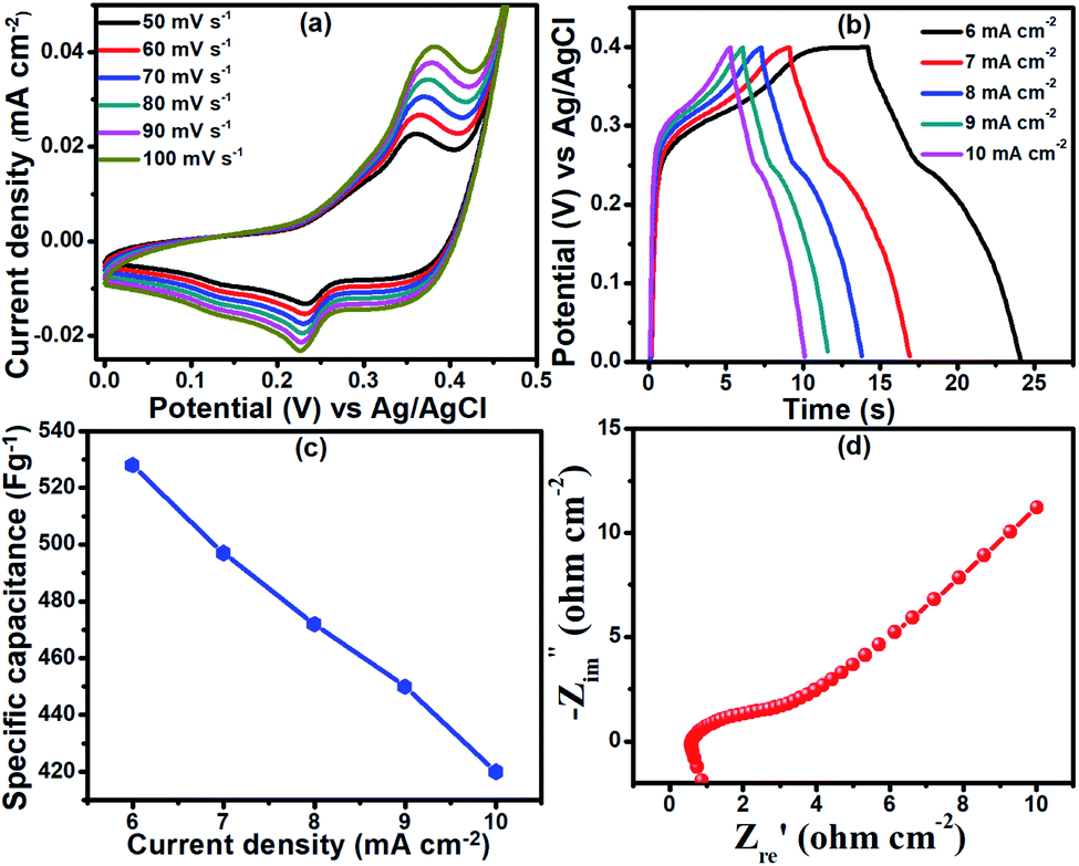 | ||
| Fig. 5 (a) CV curves at different scan rates (b) GCD curves measured at various current densities (c) the graph of specific capacitance measured at various current densities and (d) Nyquist plot of PNCO@FSSM. | ||
The oxidation and reduction peaks in CV curves reveal good symmetry, indicating that the process is reversible. Further, with the increase in the scan rate, the CV curves do not show noticeable deformation signifying that the electrode exhibits excellent rate performance. The redox peaks in the CV curves confirm the reaction mechanism and the dominance of the faradic redox mechanism. It should be emphasized that, with the increase in scan rates, the anodic peak potential and the cathodic peak potential shifts in the anodic and cathodic direction, respectively. These shifts are attributed to the fast faradaic reactions at the electrode/electrolytes interface.33 The peak current increases with an increase in scan rates when the oxidation and reduction peak shift towards the higher and lower potentials, respectively, which is indicative of the rapid transport of electrons and ions within the electrode.
GCD cycles were recorded to determine the charge storage capability of the PNCO@FSSM. All GCD cycles were recorded within the potential range of 0–0.4 V at different current densities in the range of 6–10 mA cm−2. The nonlinearity in the discharge curves (Fig. 5b) verify the pseudocapacitance behavior of NiCo2O4.33 Furthermore, smaller IR drop represents a smaller equivalent series resistance (ESR) and faster ion diffusion. The specific capacitance of the PNCO@FSSM electrode was calculated using the eqn (4). The specific capacitances of the electrode at 6, 7, 8, 9, and 10 mA cm−2 were 528, 497, 472, 450, and 420 F g−1, respectively (as shown in Fig. 5c).
EIS results of the PNCO@FSSM sample are shown in Fig. 5d, where semicircle is displayed at a higher frequency region and straight line in the low-frequency region. In general, the point intersecting the real axis in the higher frequency range reveals the equivalent series resistance (Rs) of the electrode, while the semicircles are related to the charge-transfer resistance (Rct). The slopes of the lines at the lower frequency region come from the diffusion of the electrolyte ions (Warburg's impendence) in electrode.51 The Nyquist plot, PNCO@FSSM exhibits a smaller Rs value (0.874 Ω), indicating smaller equivalent series resistance. Furthermore, Rct is 1.6 Ω which suggests smaller charge-transfer resistance. The results support the fact that good electrode and electrolyte interactions culminate in the high electrochemical performance of PNCO@FSSM.
The NiCo2O4//rGO asymmetric device is fabricated and tested to investigate the practical application of the PNCO@FSSM as the electrode materials for the energy storage device. The specific capacitance, energy density, and power density values were based on the total mass of electrode material, which was calculated using a simple weight difference method. The mass of the PNCO@FSSM positive electrode was 0.4 mg, whereas, for the (rGO@FSSM) negative electrode, it was 0.6 mg.
Fig. 6a presents the individual CV curves of the NiCo2O4 micro-flower-based electrode within the potential window of 0 to 0.5 V (vs. Ag/AgCl) and rGO electrode within the potential window of 0 to −0.9 V (vs. Ag/AgCl) at a scan rate of 60 mV s−1. Taking this as a reference, the potential window of the NiCo2O4//rGO asymmetric supercapacitor device was determined to be 1.40 V. The optimization of the potential window of the device was also performed by recording CV by varying operational potential window range within the determined range. Fig. 6b represents the CV curves of NiCo2O4//rGO device measured at different operational voltage window (0–0.4, 0–0.6, 0–0.8, 0–1.0, 0–1.2 and 0–1.4 V) at a 60 mV s−1 sweep rate. On the other hand, beyond 1.4 V and at the voltage of 1.6 V, the evolution of hydrogen and oxygen lead to the interference of the polarization of electrode.52
 | ||
| Fig. 6 Electrochemical behavior of an asymmetric supercapacitor NiCo2O4//rGO (a) CV curves of negative and positive electrodes at a scan rate of 60 mV s−1 (b) CV curves at the scan rate of 100 mV s−1 (c) CV curves (d) GCD curves (e) the specific capacitance as a function of current density, inset shows Ragone plot (power density vs. energy density) (f) cycling performance at a current density of 8 mA cm−2, inset shows the GCD curves of the last 25 cycles (g) Nyquist plot of device, before and after 2000 GCD cycles (h) schematic of the device. | ||
Fig. 6c presents the CV curves of NiCo2O4//rGO with varying sweep rates range from 40 to 100 mV s−1 in an operational voltage of 0 to 1.4 V. Fig. 6d shows the GCD curves of NiCo2O4//rGO at different current densities of 6, 8 and 10 mA cm−2. The electrochemical capacitance of the NiCo2O4//rGO asymmetric supercapacitor is calculated from discharge time and the total mass of NiCo2O4 and rGO electrodes, according to the eqn (4). The device demonstrates a specific capacitance of 214.3, 177.1, 171.4 F g−1 at a current density of 6, 8, and 10 mA cm−2, respectively, as shown in Fig. 6e. The energy densities and power densities of NiCo2O4//rGO are calculated according to eqn (5) and (6) respectively (inset of Fig. 6e). The calculated results are 41.66, 34.44, and 33.33 W h kg−1 at 2000, 3000, and 4000 W kg−1, respectively. The NiCo2O4//rGO asymmetric supercapacitor delivers a maximum energy density of 41.66 W h kg−1 at 2000 W kg−1 and the value is relatively better than those previously reported for nickel cobaltite based electrode materials.17,48,53–56 Table 1 shows the comparison of the performance of the NiCo2O4 based ASC devices reported earlier with our present report. The cycling stability of the NiCo2O4//rGO device was recorded by observing the change in specific capacitance as a function of GCD cycles (Fig. 6f). It is noted that 73.33% of its initial specific capacitance was retained even after 2000 continuous GCD cycles, revealing the outstanding cycling life of the device. Fig. 6f inset represents cyclic curves of the last twenty-five cycles with nearly the same symmetric shape demonstrating the stability of the NiCo2O4//rGO asymmetric supercapacitor device.
| Sr. No. | Device | Energy density (W h kg−1) | Power density (W kg−1) | Ref. |
|---|---|---|---|---|
| 1 | NiCo2O4//NiFe2O4 | 34.2 | 1400 | 17 |
| 2 | NiCo2O4@C//AC | 20.87 | 374.6 | 48 |
| 3 | NiCo2O4//AC | 15.78 | 1385 | 53 |
| 4 | NiCo2O4@3D-OPC//3D-OPC | 29.23 | 1550 | 54 |
| 5 | Ni/VN//NiCo2O4 | 16.25 | 263.4 | 55 |
| 6 | Co3O4/NiCo2O4//AC | 11.7 | 76 | 56 |
| 7 | PNCO@FSSM//rGO | 41.66 | 2000 | Present work |
The ion transport property within the NiCo2O4//rGO device was investigated using EIS. The EIS measurements of electrodes before and after 2000 GCD cycles at an open circuit potential of 0.28 V were carried out at the frequency range of 1000 kHz to 1 Hz in the PVA-KOH electrolyte solution. Fig. 6g represents Nyquist plots of NiCo2O4//rGO before and after the stability test. The Nyquist plots show the Rs of 0.76 Ω and 0.95 Ω before and after stability tests, respectively. The Rs value of the device increased after the stability test. The Rct is found to be 1.42 Ω and 4.34 Ω before and after the stability test, respectively. The NiCo2O4//rGO device has the lowest Rs and Rct compared with that of the NiCo2O4//rGO device after 2000 cycles. The line at the low-frequency region making an angle of 45° to the real axis is called the Warburg line and is a result of the diffusion of electrolyte ions through porous electrodes. A minimal slope difference is noted from the vertical diffusion lines, which indicate the excellent capacitive performance of the electrode before and after long-term charging/discharging. The length of the Warburg line is shorter for electrode before the stability test indicating fast ion diffusion in the porous electrodes as compared to after 2000 GCD cycles. Fig. 6h represents a schematic of the asymmetric device. The results reveal that the PNCO@FSSM electrode is one of the promising candidates for the practical application of supercapacitors in the field of energy storage. These observed excellent electrochemical performances can be attributed to the porous structures of the PNCO@FSSM micro-flower arrays and a synergistic effect of nickel and cobalt oxides in NiCo2O4.
4. Conclusions
In summary, PNCO@FSSM electrode material was fabricated by depositing marigold flower-like NiCo2O4 structures (average diameter of 5 μm having a surface area of 144.9 m2 g−1) on FSSM by a simple chemical bath deposition method followed by annealing treatment. The porosity in PNCO@FSSM provides abundant space for electron and ion transport during faradaic reactions. The PNCO@FSSM electrode exhibits an electrochemical capacitance of 528 F g−1 at 6 mA cm−2 and shows 90.5% retention of specific capacitance after 3000 cycles. The NiCo2O4//rGO asymmetric supercapacitor device delivers a maximum energy density of 41.66 W h kg−1 at a power density of 3000 W kg−1. The cyclic stability study of this device reveals 73.33% capacitance retention after 2000 cycles. The excellent electrochemical performance of the supercapacitor is attributed to the synergistic effect of nickel and cobalt oxides in NiCo2O4 which is deposited on stainless-steel substrate, porosity, and unique morphology of PNCO@FSSM. These results support that the PNCO@FSSM micro-flower structured electrode is a promising functional material for energy storage devices.Conflicts of interest
The authors declare no conflict of interest.Acknowledgements
G. P. K. is thankful to UGC, New Delhi, for the Research Fellowship (File No. F1-17.1/2016-17/RGNF-2017-18-SC-MAH-35301/(SA-III/website)). We are thankful to the Shivaji University, Kolhapur for providing funds under the project “Research Strengthening Scheme” (SU/C&U.D. Section/94/1390). We are thankful to the Department of Chemistry, Shivaji University, Kolhapur for providing the research facilities. We are thankful to Shivaji University Group for Advanced Research “SUGAR” for helpful discussion.References
- W. Fu, Y. Wang, W. Han, Z. Zhang, H. Zha and E. Xie, J. Mater. Chem. A, 2015, 4, 173–182 RSC.
- H. Niu, X. Yang, H. Jiang, D. Zhou, X. Li, T. Zhang, J. Liu, Q. Wang and F. Qu, J. Mater. Chem. A, 2015, 3, 24082–24094 RSC.
- T. Chen, Y. Fan, G. Wang, Q. Yang and R. Yang, RSC Adv., 2015, 5, 74523–74530 RSC.
- X. He, Q. Liu, J. Liu, R. Li, H. Zhang, R. Chen and J. Wang, J. Alloys Compd., 2017, 724, 130–138 CrossRef CAS.
- D. Cheng, Y. Yang, J. Xie, C. Fang, G. Zhang and J. Xiong, J. Mater. Chem. A, 2015, 3, 14348–14357 RSC.
- S. K. Patil, M. M. Vadiyar, S. C. Bhise, S. A. Patil, D. V. Awale, U. V. Ghorpade, J. H. Kim, A. V. Ghule and S. S. Kolekar, J. Mater. Sci.: Mater. Electron., 2017, 28, 11738–11748 CrossRef CAS.
- J. Li, D. Xiong, L. Wang, M. K. S. Hirbod and X. Li, J. Energy Chem., 2019, 37, 66–72 CrossRef.
- Y. Fu, D. He, R. Zhao, F. Zeng, W. Xue and W. Wang, Mater. Lett., 2016, 186, 34–37 Search PubMed.
- S. C. Bhise, D. V. Awale, M. M. Vadiyar, S. K. Patil, B. N. Kokare and S. S. Kolekar, J. Solid State Electrochem., 2017, 21, 2585–2591 CrossRef CAS.
- A. A. Kashale, K. A. Ghule, K. P. Gattu, V. H. Ingole, S. S. Dhanayat, R. Sharma, Y. C. Ling, J. Y. Chang, M. M. Vadiyar and A. V. Ghule, J. Mater. Sci.: Mater. Electron., 2017, 28, 1472–1479 CrossRef CAS.
- L. Ni, L. Jia, G. Chen, F. Wang, X. Liu and R. Ma, J. Phys. Chem. Solids, 2018, 122, 261–267 CrossRef CAS.
- A. A. Kashale, M. M. Vadiyar, S. S. Kolekar, B. R. Sathe, J. Y. Chang, H. N. Dhakal and A. V. Ghule, RSC Adv., 2017, 7, 36886–36894 RSC.
- A. A. Kashale, P. K. Dwivedi, B. R. Sathe, M. V. Shelke, J. Y. Chang and A. V. Ghule, ACS Omega, 2018, 3, 13676–13684 CrossRef CAS.
- F. M. Ismail, M. Ramadan, A. M. Abdellah, I. Ismail and N. K. Allam, J. Electroanal. Chem., 2018, 817, 111–117 CrossRef CAS.
- W. Fu, X. Li, C. Zhao, Y. Liu, P. Zhang, J. Zhou, X. Pan and E. Xie, Mater. Lett., 2015, 149, 1–4 CrossRef CAS.
- H. Gao, Y. Li, H. Zhao, J. Xiang and Y. Cao, Electrochim. Acta, 2018, 262, 241–251 CrossRef CAS.
- Y. Duan, Y. Huo, Y. Qi, L. Li, Q. Wu, C. Wang and Z. Su, J. Alloys Compd., 2018, 767, 223–231 CrossRef CAS.
- G. P. Kamble, A. A. Kashale, S. S. Dhanayat, S. S. Kolekar and A. V Ghule, Bull. Mater. Sci., 2019, 42, 272 CrossRef.
- N. R. Chodankar, D. P. Dubal, Y. Kwon and D.-H. Kim, NPG Asia Mater., 2017, 9, e419 CrossRef CAS.
- S. Wen, Y. Liu, H. Bai, R. Shao, W. Xu and W. Shi, J. Solid State Chem., 2018, 262, 327–334 CrossRef CAS.
- D. Zhao, X. Wu and C. Guo, Inorg. Chem. Front., 2018, 5, 1378–1385 RSC.
- J. Fang, C. Kang, L. Fu, S. Wan and Q. Liu, J. Alloys Compd., 2019, 804, 1–9 CrossRef CAS.
- J. Zhang, P. S. Shewale and K. Yun, Energies, 2019, 12, 3127 CrossRef CAS.
- H. Jiu, L. Jiang, Y. Gao, Q. Zhang and L. Zhang, Ionics, 2019, 4325–4331 CrossRef CAS.
- X. Lv, W. Li, Z. Ren, Y. Liu, X. Chang, M. He and X. Zheng, J. Alloys Compd., 2019, 784, 293–300 CrossRef.
- W. Zhang, W. Xin, T. Hu, Q. Gong, T. Gao and G. Zhou, Ceram. Int., 2019, 45, 8406–8413 CrossRef CAS.
- M. Mirzaee and C. Dehghanian, Mater. Today Energy, 2018, 10, 68–80 CrossRef.
- R. B. Waghmode and A. P. Torane, J. Mater. Sci.: Mater. Electron., 2016, 27, 6133–6139 CrossRef CAS.
- P. Osaimany, A. S. Samuel, Y. Johnbosco, Y. P. Kharwar and V. Chakravarthy, Composites, Part B, 2019, 176, 107327 CrossRef CAS.
- F. Yang, K. Zhang, W. Li and K. Xu, J. Colloid Interface Sci., 2019, 556, 386–391 CrossRef CAS.
- Q. Zhang, H. Chen, J. Wang, D. Xu, X. Li, Y. Yang and K. Zhang, ChemSusChem, 2014, 7, 2325–2334 CrossRef CAS.
- R. Zhang, M. Liu, W. Liu and H. Wang, Mater. Lett., 2017, 199, 164–167 CrossRef CAS.
- S. Wu, F. Xue, M. Wang and J. Wang, Integr. Ferroelectr., 2018, 189, 158–164 CrossRef CAS.
- S. K. Shinde, M. B. Jalak, G. S. Ghodake, N. C. Maile, H. M. Yadav, A. D. Jagadale, A. Shahzad, D. S. Lee, A. A. Kadam, V. J. Fulari and D. Y. Kim, Ceram. Int., 2019, 45, 17192–17203 CrossRef CAS.
- S. Dang, Z. Wang, W. Jia, Y. Cao and J. Zhang, Mater. Res. Bull., 2019, 116, 117–125 CrossRef CAS.
- J. Zhang, Y. Wang, C. Yu, T. Zhu, Y. Li, J. Cui, J. Wu, X. Shu, Y. Qin, J. Sun, J. Yan, Y. Zhang and Y. Wu, J. Mater. Sci., 2020, 55, 688–700 CrossRef CAS.
- M. Kundu, G. Karunakaran, E. Kolesnikov, V. E. Sergeevna, S. Kumari, M. V. Gorshenkov and D. Kuznetsov, J. Ind. Eng. Chem., 2018, 59, 90–98 CrossRef CAS.
- H. Fu, Y. Liu, L. Chen, Y. Shi, W. Kong, J. Hou, F. Yu, T. Wei, H. Wang and X. Guo, Electrochim. Acta, 2019, 296, 719–729 CrossRef CAS.
- J. Xu, Y. Sun, M. Lu, L. Wang, J. Zhang, E. Tao, J. Qian and X. Liu, Acta Mater., 2018, 152, 162–174 CrossRef CAS.
- M. M. Vadiyar, S. C. Bhise, S. K. Patil, S. S. Kolekar, J. Y. Chang and A. V. Ghule, ChemistrySelect, 2016, 1, 959–966 CrossRef CAS.
- M. M. Vadiyar, S. S. Kolekar, J. Y. Chang, A. A. Kashale and A. V. Ghule, Electrochim. Acta, 2016, 222, 1604–1615 CrossRef CAS.
- M. F. El-Kady, V. Strong, S. Dubin and R. B. Kaner, Science, 2012, 335, 1326–1330 CrossRef CAS.
- S. Nagamuthu, S. Vijayakumar, S. H. Lee and K. S. Ryu, Appl. Surf. Sci., 2016, 390, 202–208 CrossRef CAS.
- R. Prasad and P. Singh, Catal. Sci. Technol., 2013, 3, 3223–3233 RSC.
- H. Chen, G. Jiang, W. Yu, D. Liu, Y. Liu, L. Li, Q. Huang and Z. Tong, J. Mater. Chem. A, 2016, 4, 5958–5964 RSC.
- A. K. Mondal, D. Su, S. Chen, A. Ung, H. S. Kim and G. Wang, Chem. - Eur. J., 2015, 21, 1526–1532 CrossRef CAS.
- T. Wu, Q. He, J. Yang, Z. Wen, X. Ao, S. Gu and S. Zhang, Chem. Eng. J., 2017, 330, 764–773 CrossRef.
- G. Yang and S. J. Park, Electrochim. Acta, 2018, 285, 405–414 CrossRef CAS.
- S. Yuvaraj, A. Vignesh, S. Shanmugam and R. Kalai Selvan, Int. J. Hydrogen Energy, 2016, 41, 15199–15207 CrossRef CAS.
- X. Ge, Y. Liu, F. W. T. Goh, T. S. A. Hor, Y. Zong, P. Xiao, Z. Zhang, S. H. Lim, B. Li, X. Wang and Z. Liu, ACS Appl. Mater. Interfaces, 2014, 6, 12684–12691 CrossRef CAS.
- C. Liu, W. Jiang, F. Hu, X. Wu and D. Xue, Inorg. Chem. Front., 2018, 5, 835–843 RSC.
- B. Kirubasankar, V. Murugadoss and S. Angaiah, RSC Adv., 2017, 7, 5853–5862 RSC.
- J. Bhagwan, G. Nagaraju, B. Ramulu, S. C. Sekhar and J. S. Yu, Electrochim. Acta, 2019, 299, 509–517 CrossRef CAS.
- Z. Wang, S. Luo, M. Sun, K. Dong, Y. Liu and D. Wang, J. Alloys Compd., 2018, 783, 1–9 Search PubMed.
- C. Ji, Z. Li, M. Xu, L. Liu and H. Mi, Solid State Ionics, 2018, 324, 168–175 CrossRef CAS.
- Y. Wei, C. Zhang, L. Wang, Z. Yan, S. Cui, L. Hou, C. Jia, C. Guo, T. Li and L. Xu, J. Nanosci. Nanotechnol., 2018, 19, 47–56 Search PubMed.
| This journal is © The Royal Society of Chemistry 2021 |