
 Open Access Article
 This Open Access Article is licensed under a Creative Commons Attribution-Non Commercial 3.0 Unported Licence
Endowing magnesium with the corrosion-resistance property through cross-linking polymerized inorganic sol–gel coating†
Wei Wang ,
Xiao-Na Yang,
Yang Wang,
Yong Fan and
Jia-Ning Xu*
,
Xiao-Na Yang,
Yang Wang,
Yong Fan and
Jia-Ning Xu*
College of Chemistry, Jilin University, Changchun 130012, China. E-mail: xujn@mail.jlu.edu.cn
First published on 22nd January 2021
Abstract
The design of a highly adhesive, defect-free and low-temperature sol–gel coating for the protection of magnesium alloys is desirable yet challenging. In this study, a novel SiO2-based sol–gel coating is developed by a ring-opening addition reaction. Notably, the integration of individual sol clusters endows the sol–gel coating with a smooth and compact surface morphology, and eliminates the potential corrosion site of the low-temperature-prepared sol–gel coating. Besides, the as-obtained sol–gel coating exhibits excellent metallic adhesion nature. Most importantly, it increases the overall impedance modulus by 27 times than that of the conventional strategy and decreases the corrosion rate from 3.8 ± 0.5 mg cm−2 per day (commercial chromate conversion coating) to 0.5 ± 0.2 mg cm−2 per day.
1. Introduction
While magnesium (Mg) alloys have attracted considerable attention owing to their excellent mechanical and biological properties, the poor corrosion-resistance property has brought numerous obstacles to the application of Mg alloys.1–3 The oxide coating prepared by the sol–gel technology outperforms other methods in terms of high adhesion with a metallic substrate, and superior corrosion-resistance.4,5 However, the conventional preparation process requiring high-temperature annealing process (400–800 °C) brings additional thermal energy consumption and undesirable changes in the microstructure of heat-sensitive Mg alloys (melting point, ∼650 °C).6 Moreover, cracks and other physical defects are inevitable in the oxide-based sol–gel coating due to the evaporation of catalysts (hydrochloric acid, nitric acid or acetic acid, etc.) in the thermal treatment, which provides numerous vulnerable sites for initiating corrosion.7 Although researchers have developed numerous preparation strategies to avoid the thermal process, these strategies had to be carried out at the expense of metallic adhesion and/or environmental pollution.8–10 Therefore, a method to prepare corrosion-resistant sol–gel coating under mild and environmentally benign conditions is urgently needed.In the preparation process of the sol–gel coating, the high-temperature treatment aims to increase the interaction between sol clusters and stabilize physical and chemical properties.6,7 Recently, click chemistry has become one of the most powerful paradigms in the synthesis and modification of materials.11 Among these, the ring-opening addition reaction (AORA) of epoxy groups is broadly applied in the synthesis of polymer matrices and in the introduction of functional group.12,13 Thus, we hypothesized that the physical integration and subsequent corrosion protection of sol–gel coatings can be improved by the AORA of epoxy groups that polymerize each of the relatively independent clusters. The polymeric hybridization nature of clusters is highly likely to have a trivial impact on the coating bonding strength of the metal substrate.
Herein, AORA as an isolated parameter was studied on a SiO2 based sol–gel coating to establish its role in the anti-corrosion performance by taking a neat Mg as a model metallic material due to its simple composition. In brief, epoxy groups were introduced into the precursor sol of ZrO2 and SiO2 via 3-glycidyloxypropyltrimethoxysilane, and then cured by a small amount of 2-methylimidazole at a low temperature (≤80 °C). Owing to the polymerization process of introduced epoxy groups, the surface morphology of the obtained coating is very smooth, flat and crack-free than that of the conventionally prepared sol–gel coating. More importantly, unchanged covalent-bond-based binding characteristics maintain a high adhesion level of the modified sol–gel coating (the highest level in the ISO-2049:2013 standard). As expected, the modified sol–gel coating shows excellent performance in corrosion resistance compared with that of conventional sol–gel coatings and commercial chromate conversion coatings.
2. Experimental section
2.1. Chemicals
All chemicals were commercially available and used as received in the present study. Tetraethoxysilane (TEOS, 99%), 3-glycidyloxypropyltrimethoxysilane (GPTMS, 97%), zirconyl chloride octahydrate (ZrOCl2·8H2O, 99%), isopropyl alcohol (99.5%), absolute ethanol (99.7%) and 2-methylimidazole (98%) were all purchased from Aladdin Bio-Chem Technology Co. Ltd., Shanghai, China. Hydrochloric acid (HCl, 36.0–38.0 wt%), sodium chloride (NaCl, 98%), sodium dichromate dihydrate (Na2Cr2O7, 99.5%), magnesium fluoride (MgF2, 98%), ammonium bifluoride (NH4HF, 98%), chromium trioxide (CrO3, 99%), silver nitrate (AgNO3, 99.8%), barium nitrate (Ba(NO3)2, 99.5%) and acetone (99.5%) were supplied by Beijing Chemical Reagents Co. Ltd., China.2.2. Mg substrate specimens
High purity Mg specimens (>99.9%, Fe ≤ 40 ppm) were cut off from an as-cast ingot into 15 × 15 × 3 mm3 square pieces. The specimen was mechanically ground with silicon carbide papers progressively up to 2000-grit surface finish and running water as the lubricant, and ultrasonically cleaned in acetone and absolute ethanol for 30 min. Subsequently, the Mg specimen was immersed in 1 M NaOH aqueous solution at 80 °C for 4 h to create a thin layer of porous Mg(OH)2 to improve the adhesion for subsequent sol–gel coating, followed by rinsing with deionized water and ethanol, and then dried under a high pressure nitrogen flow.2.3. The preparation of commercial chromate conversion coating
According to an open publication,14 an aqueous solution containing 120 g L−1 Na2Cr2O7 and 2.5 g L−1 MgF2 was prepared to produce commercial chromate coatings on the Mg substrate for comparison. Before exposing to the chromate solution, the Mg substrate was immersed into an aqueous solution containing 50 g L−1 NH4HF for 300 s to activate its surface. Thereafter, the Mg substrate was placed in the aforementioned boiled chromate solution for 30 min, followed by rinsing with hot water (60–70 °C) and dried under airflow at room temperature, and thus named as the CM coating.2.4. The preparation of Si02@ZrO2 sol–gel coatings
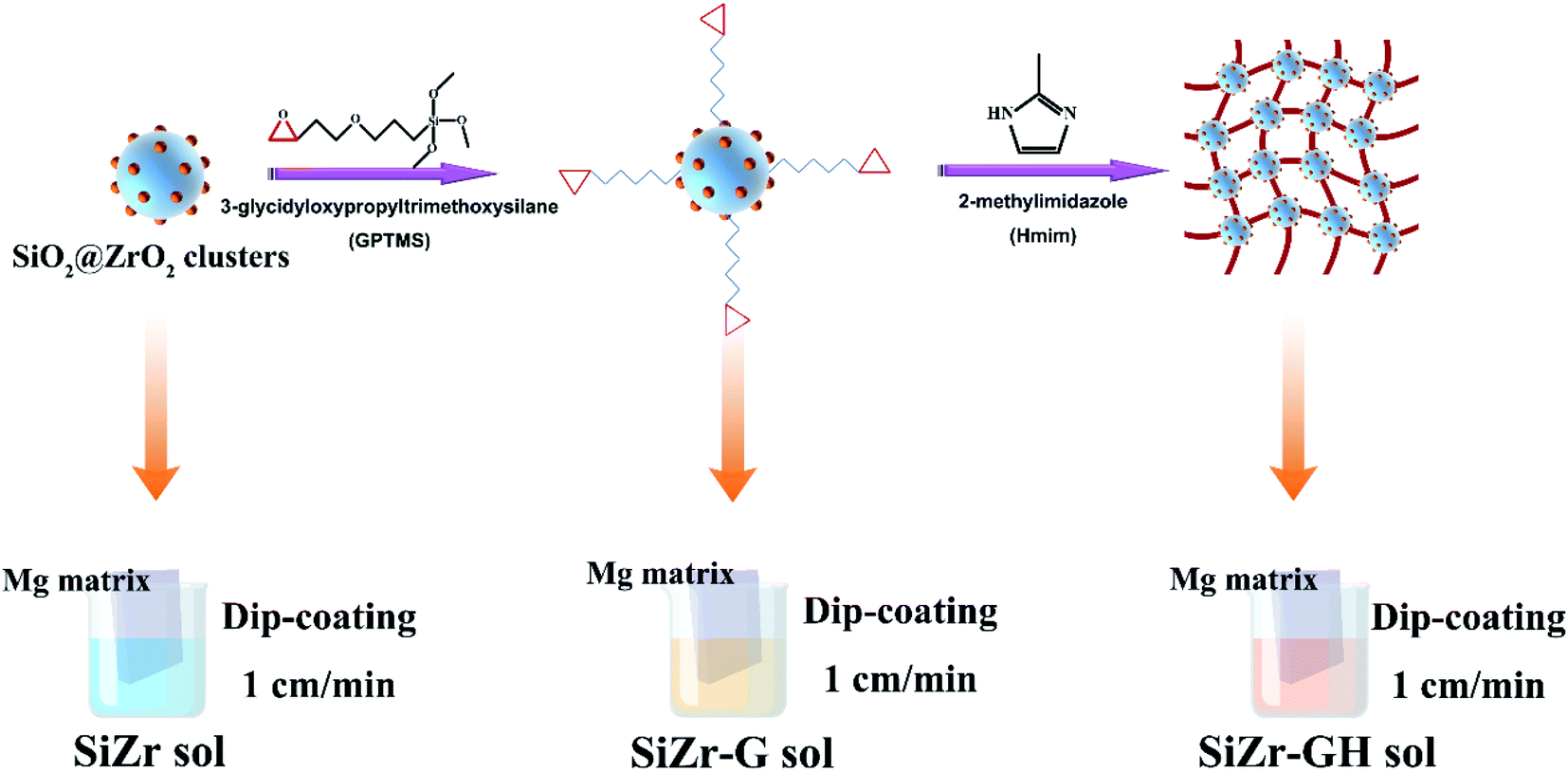
The preparation process of the sol–gel coating was optimized according to the method in the ESI.† Briefly, 4.73 mL TEOS (19.76 mmol) was added into a mixed solvent composed of 2.5 mL ethanol and 2.5 mL isopropyl alcohol. Thereafter, 335.1 mg ZrOCl2 (1.04 mmol, nSi![[thin space (1/6-em)]](https://www.rsc.org/images/entities/char_2009.gif) :nZr = 5:95) was added into the solution. When all solid substances were dissolved, 375 μL HCl aqueous solution (20.8 mmol H2O, pH = 2) and 3.96 mL GPTMS (15.7 mmol) were transferred drop-wise into the clear solution. The pH value of the HCl solution used in the preparation procedure was monitored using an electrolyte-type pH meter (PB-10, Sartorius, Germany). Finally, 20 mg 2-methylimidazole (0.244 mmol) was added. Magnetic stirring was applied to all procedures. The as-prepared solution was hydrolyzed and polymerized at room temperature for 1 h to obtain the sol. A dip coating technique was employed to grow SiO2@ZrO2 (designated as SiZr-GH hereafter) sol–gel coatings on the surface of Mg specimens. In brief, the Mg piece was fully immersed in the sol for 10 s and lift up vertically through an electric-motor-driven arm at a speed of 1 cm min−1. Thereafter, SiZr-GH sol-covered Mg species were cured in an oven at 80 °C for 4 h. In addition, 2-methylimidazole-free sol–gel coatings (SiZr-G), and GPTMS- and 2-methylimidazole-free sol–gel coatings (SiZr) were prepared as controls for comparison.
:nZr = 5:95) was added into the solution. When all solid substances were dissolved, 375 μL HCl aqueous solution (20.8 mmol H2O, pH = 2) and 3.96 mL GPTMS (15.7 mmol) were transferred drop-wise into the clear solution. The pH value of the HCl solution used in the preparation procedure was monitored using an electrolyte-type pH meter (PB-10, Sartorius, Germany). Finally, 20 mg 2-methylimidazole (0.244 mmol) was added. Magnetic stirring was applied to all procedures. The as-prepared solution was hydrolyzed and polymerized at room temperature for 1 h to obtain the sol. A dip coating technique was employed to grow SiO2@ZrO2 (designated as SiZr-GH hereafter) sol–gel coatings on the surface of Mg specimens. In brief, the Mg piece was fully immersed in the sol for 10 s and lift up vertically through an electric-motor-driven arm at a speed of 1 cm min−1. Thereafter, SiZr-GH sol-covered Mg species were cured in an oven at 80 °C for 4 h. In addition, 2-methylimidazole-free sol–gel coatings (SiZr-G), and GPTMS- and 2-methylimidazole-free sol–gel coatings (SiZr) were prepared as controls for comparison.
2.5. The measurement of physical and chemical features
Sol–gel coatings were characterized via Fourier transform infrared spectroscopy (FTIR, Nicolet™ iS™ 10, ThermoFisher Scientific, US), X-ray photoelectron spectroscopy (XPS, ESCALAB™, ThermoFisher Scientific, USA) and scanning electron microscopy (SEM, SU8020, HIACHI, Japan).The reaction progress of SiZr-GH sol–gel coatings were evaluated by FTIR and spectra were recorded over a range of 4000–400 cm−1. Samples were prepared in two different ways: (a) no curing: sol solution droplet on KBr disc; and (b) cured: part of sol–gel coating was mixed with KBr powder and compressed into disc. The surface morphology of samples was revealed through SEM high-resolution images.
In the XPS study, photoelectrons generated by Al Kα (1486.6 eV) primary radiation (20 kV, 15 mA) were analyzed with a hemispherical analyzer, and core level XPS spectra for Si 2p, Zr 3d, Mg 2p, O 1s and C 1s were recorded and fitted. Binding energy was calibrated with the standard C 1s (hydrocarbon C–C, C–H) value of 285 eV. Data were quantitatively assessed using a one-way factorial analysis of the variance method.
2.6. Adhesion strength testing
The adhesion of substrates and coatings was determined referring to a standard ISO-2049:2013 cross-cut test.15 In brief, a 100-cell grid was drawn out on a sol–gel coating with a spacing of 1 mm between grid blades. Then, a transparent adhesive tape (Cat. 600, 3 M) was firmly placed upon the affected area, followed by quick peeling off to observe the remaining surface of the coating with an optical microscope. The adhesion level was determined by the ratio of the area of remaining coating to that of the original coating, and the larger ratio indicates the high adhesion level.2.7. Analysis of electrochemical performance
For electrochemical tests, a “flat-cell” (F030, Tianjin Ida, China) equipped with an exposed working electrode (Mg specimens) of area 1 cm2, and Ag/AgCl and a Pt mesh as reference and counter electrodes, respectively, containing 300 mL of NaCl (0.6 M) electrolyte was used. Electrochemical experiments were performed on a CHI760E (CH Instruments, China) potentiostat/galvanostat using the CHI 16.06 software at a sweeping rate of 10 mV s−1. Potentiodynamic polarization curves were recorded after 10 min stabilization at an open circuit potential (OCP) and used to estimate the corrosion potential (Ecorr) and corrosion current density (icorr) via Tafel fitting using the CHI 16.06 software. In general, a portion of the curve that commences >50 mV from the corrosion potential was selected, and Ecorr and icorr were subsequently estimated from the value where the fit intercepted the potential value of the true corrosion potential. A minimum of five replicate scans were performed for each material group to ensure reproducibility. Electrochemical impedance spectroscopy (EIS) was conducted over a frequency range from 100 kHz to 10 mHz, with a sinusoidal amplitude of 10 mV and same after 10 min of OCP conditioning. EIS data were analyzed using ZSimpWin (version 3.10) software. All electrochemical tests were carried out in a Faraday cage to avoid interferences.2.8. Mass loss in aqueous NaCl electrolyte
To examine the long-term corrosion performance of coatings, mass loss was carried out in 0.6 M NaCl at room temperature for 28 days. The exposed surface area of each specimen in contact with 10 mL NaCl solution was constantly set as 6.3 cm2. After immersion, specimens were removed from the NaCl electrolyte and cleaned in a solution containing 200 g L−1 CrO3, 20 g L−1 AgNO3 and 10 g L−1 Ba(NO3)2 for 1 min at room temperature to remove corrosion products from the surface, according to industrial standards ISO-8407:2009.16 The variations of mass after immersion and cleaning procedures were divided by the surface area of specimens and immersion time to yield mass loss rate (mg cm−2 per day). Three minimal replicates were carried out for each data point to ensure reproducibility (n = 3).2.9. Statistical analysis
All quantitative results were expressed as mean ± standard deviation (SD). Statistical significance was determined by Student's t-test and one-way ANOVA. Differences between the groups of *p values (<0.05) were considered statistically significant.3. Results and discussion
3.1. Formation mechanism of the modified sol (SiZr-GH) coating
Scheme 1 illustrates the detailed procedure for the preparation of SiZr-GH sol–gel coating. Firstly, a mixture of tetraethoxysilane (TEOS) and zirconia chloride (ZrOCl2) was hydrolyzed in the mixed solvent of ethanol and isopropyl alcohol (volume ratio, 1:1) to form the precursor sol. Thereafter, 3-glycidyloxypropyltrimethoxysilane (GPTMS) was drop-wise added into the above solution for introducing the epoxy groups on the sol clusters at room temperature. Afterward, 2-methylimidazole (curing agent) was added under magnetic stirring and then the solution was coated upon the Mg substrates by the dip-coating technology. Finally, the sol–gel coating was cured at 80 °C in an oven for 4 h.
 | ||
| Scheme 1 The schematic of reaction processes and modified sol–gel coating. | ||
FTIR spectra were recorded to determine the occurrence of the ring-opening addition reaction during the preparation process of SiZr-GH coating. As depicted in Fig. 1, the stretching vibration absorption peaks of the epoxy group at about 910 cm−1 disappeared after the curing step. Such variations indicate that epoxy groups experienced a ring-opening addition reaction when 2-methylimidazole was added, which led to the chemical bonding of individual clusters and may increase the cross-linking density of the SiZr-GH sol.
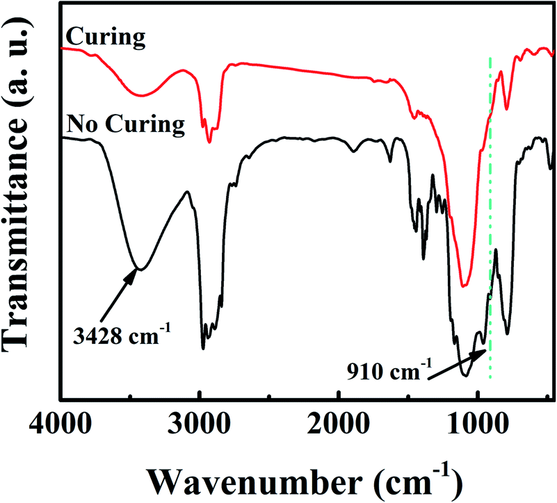 | ||
| Fig. 1 The FTIR spectra of SiZr-GH sol before and after the curing process. | ||
The increase in cross-linking density will result in a compact, continuous and defect-free surface morphology,17–19 which is highly desirable to play an inhibitory role in controlling the corrosion behaviour of underlying metal components.20 Accordingly, we observed variations in the surface morphology of the sol–gel coating prior to and after GPTMS and 2-methylimidazole modification by scanning electron microscopy (SEM) and energy dispersive spectroscopy (EDS). The surface of the modified free sol–gel coating (SiZr) exhibited pronounced cracks and a great number of scattering particles with regular edges (Fig. 2a). Alternatively, as shown in Fig. 2b, the number of these particles was significantly reduced on the surface of the GPTMS-improved sol–gel coating (SiZr-G). The surface morphology was further improved by the modification of GTPMS and 2-methylimidazole (SiZr-GH); the ultimate target, i.e., sol–gel coating, presents a dense, continuous and smooth surface (Fig. 2c). This suggests that the ring-opening addition reaction polymerization strategy is beneficial in restraining the formation of physical defects in the sol–gel coating prepared at room temperature. In addition, scattering particles with regular edges that upon SiZr and SiZr-G sol–gel coating, have been determined to mainly magnesium oxide through EDS mapping. Owing to the limited cross-linking density of the sol–gel coating prepared at a low temperature, it is relatively loose in most cases,20 which leads to the reaction between the Mg substrate and oxygen to obtain these particles mainly made of magnesium oxide. In summary, the smooth and defect-free surface of the SiZr-GH sol–gel coating set a fundamental basis for further application.
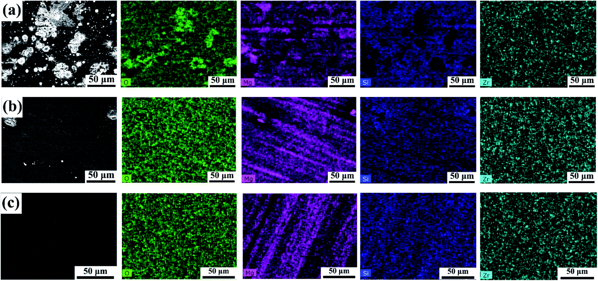 | ||
| Fig. 2 SEM and EDS mapping images of the as-prepared sol–gel coating. (a) Modified free sol–gel coating (SiZr), (b) GPTMS-modified sol–gel coating (SiZr-G) and (c) GTPMS and 2-methylimidazole-modified sol–gel coating (SiZr-GH). | ||
3.2. Coating adhesion strength
A high bonding strength of the sol–gel coating towards an underlying metal substance is crucial for its protective role in corrosive conditions over a sufficient time frame.21–23 In general, existing low-temperature modification approaches for the preparation of the sol–gel coating involve macromolecular polymer compounds, which tend to have adverse effects on the adhesion of the sol–gel coating.24,25 To validate the metallic adhesion of the modified sol–gel coating, cross-cut tests were conducted. Results displayed in Fig. 3a–c evidently indicate that the adhesion strength of SiZr, SiZr-G and SiZr-GH sol–gel coatings upon Mg specimens was ascertained as grade 0, which is the highest level of coating based on ISO-2049:2013 standards.15 From the cross-sectional SEM images (Fig. 3d–f), there is no clear dividing line between the coating and Mg substrates and possessed a continuous, uniform and compact morphology. The ring-opening addition reaction-based preparation process avoided significant interface separation and adhesive property damages compared to the polymer hybrid sol–gel coating.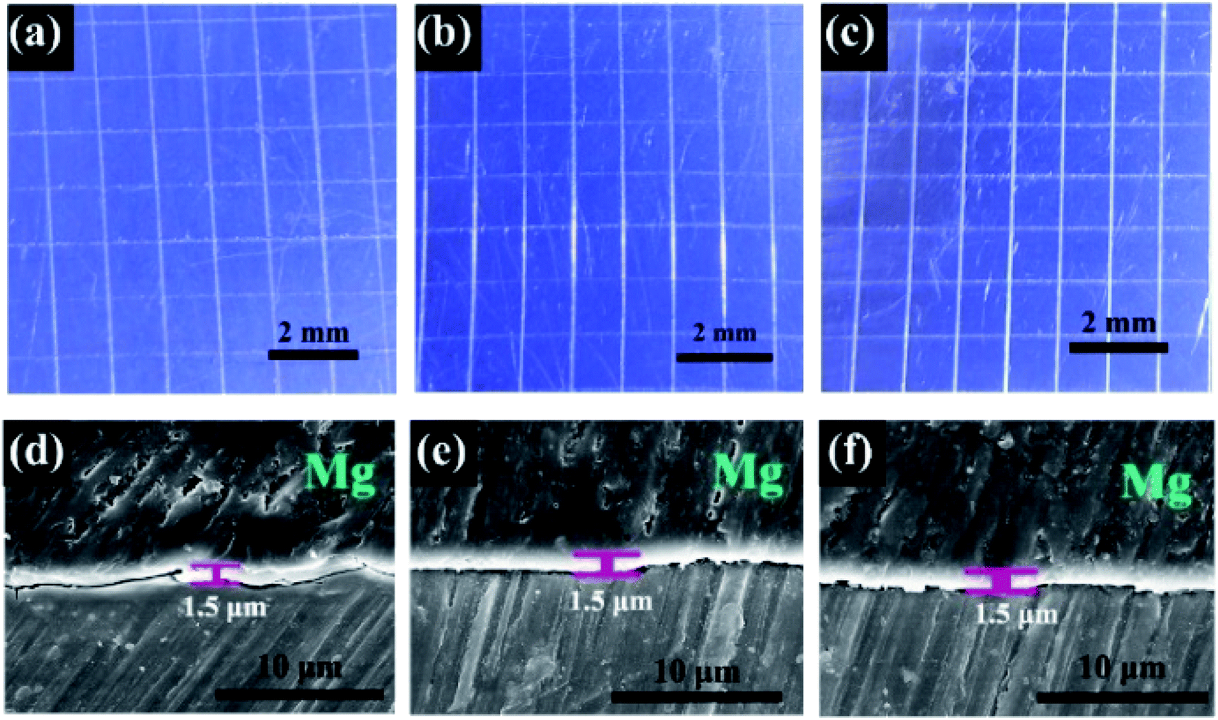 | ||
| Fig. 3 (a–c) Optical photographs of the surface of (a) SiZr, (b) SiZr-G and (c) SiZr-GH sol–gel coatings on pure Mg substrate after designated adhesion tests through the cross-cut test according to the standards of ISO-2049:2013.15 SEM images of the cross-sectional micrography, (d) SiZr, (e) SiZr-G and (f) SiZr-GH sol–gel coating. | ||
In addition, X-ray photoelectron spectroscopy (XPS) was used to further study the influence of the modification process on covalent-bond-based binding characteristics of the sol–gel coating. The XPS spectrum demonstrates that numerous covalent oxygen bonds existed in the SiZr-GH sol–gel coating (Fig. 4), and Mg–O bonds especially provide a chemical path for the sol–gel coating to bind with the metal substrate (pure Mg), which is consistent with the binding characteristic of the conventional sol–gel coating.26 A balance between mild preparation conditions and the metallic adhesion was created by our preparation strategy, which eliminates the potential corrosion site without changing the adhesion property of the sol–gel coating.
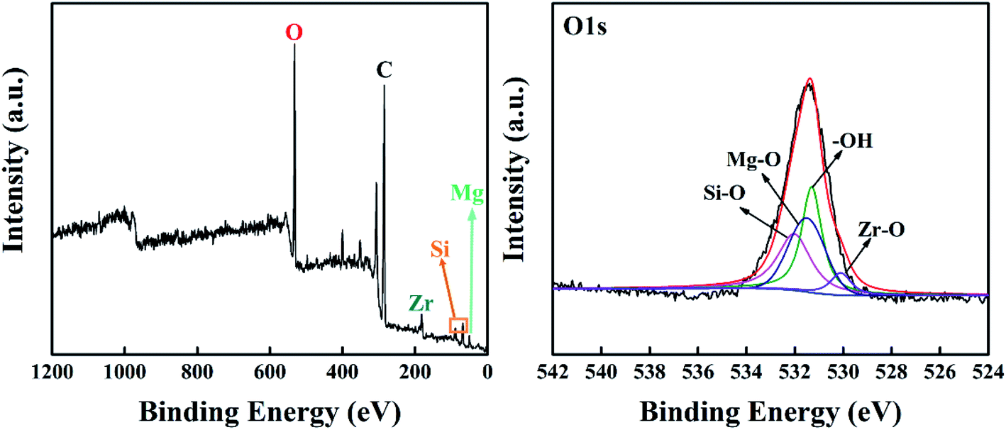 | ||
| Fig. 4 XPS survey spectra and O1s peak-fitted curves of the surface of SiZr-GH sol-coated pure Mg. | ||
3.3. Electrochemical analysis for corrosion-resistance performance
In the following part, the corrosion protection performance of the as-prepared sol–gel coating was evaluated via electrochemical tests and was compared with that of the conventional sol–gel coating and commercial coating. Potentiodynamic polarization (PDP) curves are a common technique to quantify the instant corrosion kinetics of bare and coated Mg specimens in a corrosive electrolyte, such as the NaCl solution.27–31 To examine the protective function of SiZr-GH sol–gel coatings on pure Mg, PDP curves were recorded in a 0.6 M neutral NaCl solution over a potential range from −150 mV to 600 mV vs. the open circuit potential (OCP). It is evident that the polarization curves of all coatings shifted to the lower corrosion current density region and both cathodic and anodic current densities reduced but to different extents (Fig. 5a). This illustrates that the corrosion of Mg is kinetically inhibited since the cathodic branch is assumed to represent the hydrogen evolution through water reduction and the anodic branch is related to the Mg dissolution.32 The icorr of all coatings showed a reduction in comparison with that of the neat Mg specimen, as well as a further decrease on the SiZr-GH coating by an order of magnitude. This benefits individual sol clusters integrated by the ring-opening addition reaction, which improves the surface morphology of the SiZr-GH coating and eliminates the potential corrosion sites (Fig. 2). Moreover, the icorr of pure Mg increases gradually with the surface morphology of the sol–gel coating upon its top deterioration (e.g. SiZr-G and SiZr), which proves the above conjecture.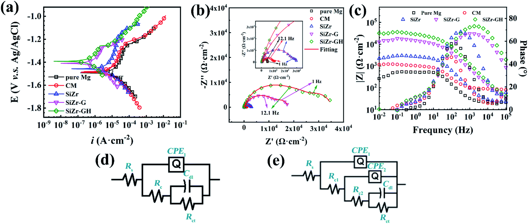 | ||
| Fig. 5 (a) Potentiodynamic polarization curves of bare Mg and various coatings obtained at a sweep rate of 10 mV s−1; (b) the estimated average value of Ecorr and icorr through Tafel fitting extrapolation via CHI 16.06 software (n = 5); EIS plots in (a) Nyquist and (b) Bode formats with corresponding fitting data collected over a period of 30 min (after 10 min OCP stabilization) (n = 3) over a range of frequency from 100 kHz to 10 mHz; equivalent circuit used to fit the EIS data of (c) pure Mg specimen, and (d) chromate conversion coating and sol–gel coating. (e), but this does not appear to be mentioned in the caption. Would you like to modify the caption or resupply the artwork (preferably as a TIF file at 600 dots per inch)? | ||
EIS measurements were collected immediately following 10 min stabilization at OCP during exposure to the 0.6 M neutral NaCl solution. The high-frequency (1–105 Hz) loop corresponds to the charge resistance of materials, whilst the response from the electrochemical double layer can be reflected by the semi-circle located in the low-frequency range (0.01–1 Hz).33,34 From Nyquist plots in Fig. 5b, the high-frequency loop of the SiZr-GH sample is larger than other coatings sharply increasing in the order of pure Mg < CM < SiZr < SiZr-G < SiZr-GH. Furthermore, the value of |Z|0.01Hz is an essential indicator for assessing the corrosion resistance of materials and represents the value of the overall impedance modulus.35,36 From Bode plots in Fig. 5c, the |Z|0.01 Hz value of the SiZr-GH sample (31.9 kΩ cm−2) increased by approximately 27 times compared to that of CM (1.2 kΩ cm−2) and conventional SiZr sol–gel coating (2.2 kΩ cm−2). Furthermore, we proposed several equivalent circuits (Fig. 5d and e) to fit EIS results: Rs(CPE(Rc(CdlRct))) was used for fitting the EIS data of pure Mg, and Rs(CPE1(Rc1(CPE2(Rc2(CdlRct))))) was used for fitting the EIS data of CM and sol–gel coatings. In these circuits, Rs represents the solution resistance; Cdl and Rct represent the double-layer capacitance and charge transfer resistance, respectively; CPE represents the capacitance of the film effect and Rc represents the total resistance of pores or coating. The polarization resistance (Rp), which is the sum of Rct and Rc, is proposed to evaluate the corrosion resistance. The fitting data (Table 1) further indicate that the ring-opening addition reaction-modified sol–gel coating endowed neat Mg with desired corrosion-resistance performance, which was due to the integration of sol clusters and the improvement of surface morphology.
| Pure Mg | CM | SiZr | SiZr-G | SiZr-GH | ||
|---|---|---|---|---|---|---|
| Rs (Ω cm−2) | 21.91 | 0.01 | 1.489 | 22.79 | 25.42 | |
| Rc1 (Ω cm−2) | 158.8 | 91.47 | 22.78 | 1.345 × 10⁴ | 2.186 × 10⁴ | |
| CPE1 | F cm−2 s1−n | 1.261 × 10⁻⁵ | 7.398 × 10⁻⁷ | 2.427 × 10⁻⁸ | 1.526 × 10⁻⁶ | 5.335 × 10⁻⁷ |
| n | 0.9389 | 0.8097 | 0.9668 | 0.773 | 0.8359 | |
| Rc2 (Ω cm−2) | — | 932.6 | 2595 | 4305 | 8021 | |
| CPE2 | F cm−2 s1−n | — | 1.692 × 10⁻⁵ | 5.467 × 10⁻⁶ | 4.969 × 10⁻⁵ | 8.701 × 10⁻⁶ |
| n | — | 0.8492 | 0.87 | 0.9146 | 0.8089 | |
| Cdl (F cm−2) | 4.996 × 10⁻⁶ | 2.941 × 10⁻³ | 5.973 × 10⁻³ | 7.191 × 10⁸ | 4.28 × 10⁻⁵ | |
| Rct (Ω cm−2) | 35.72 | 143.3 | 380.4 | 6.168 × 10⁶ | 5294 | |
| Chi-squared | 1.86 × 10⁻³ | 2.53 × 10⁻⁴ | 9.15 × 10⁻⁵ | 8.41 × 10⁻⁴ | 9.87 × 10⁻⁴ | |
3.4. Long-term corrosion-resistance performance
Though electrochemical techniques provided critical information regarding instant anodic dissolution kinetics and interfacial states of the sol-coated pure Mg specimens, direct evidence in terms of the long-term corrosion progress of coated Mg parts is also essentially desired. In this regard, the long-term corrosion behavior of coating-protected pure Mg was explored via mass loss tests in the 0.6 M neutral NaCl solution for 28 days. Three groups of coatings were designed to assess the possible contributions from each individual factor to corrosion protection property, namely commercial chromate conversion coating (CM), SiZr and SiZr-GH. The SEM observation (Fig. 6) qualitatively indicates that the corrosion resistance is in the order of SiZr-GH > SiZr > CM. After exposure to the NaCl solution for 28 days, a small number of corrosion products were generated on the surface of SiZr-GH, while SiZr and CM accumulated a large amount of platelet-shaped corrosion products in a loose manner. Thus, this suggests the following points: (a) sol–gel coating demonstrates better corrosion resistance than that of the commercial chromate conversion coating, and (b) our designed sol–gel coating preparation strategy exhibits great improvement in the corrosion protection property.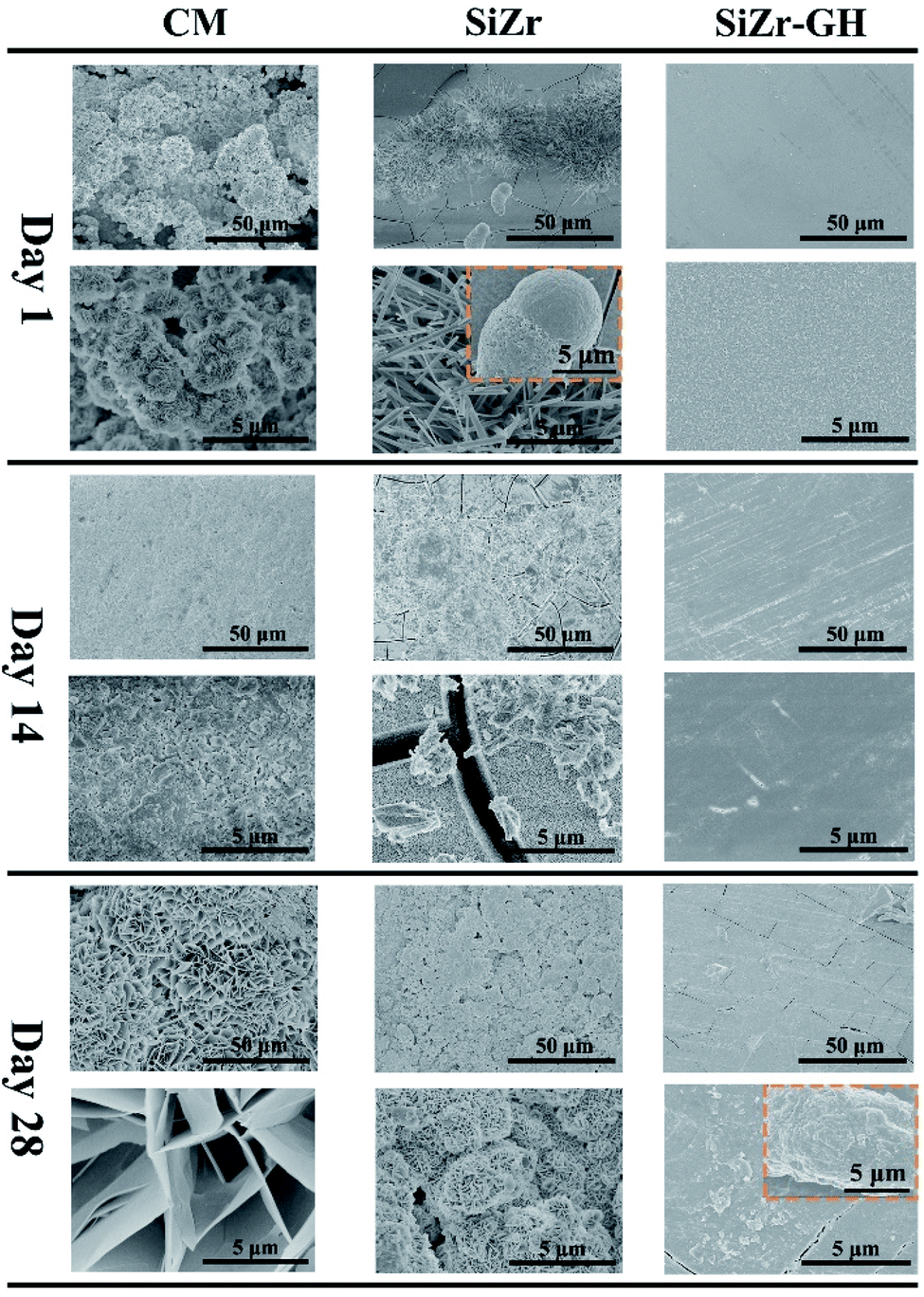 | ||
| Fig. 6 Top-view secondary electron scanning microscopy graphs of various coating samples after immersion in 0.6 M neutral NaCl for 1, 14 and 28 days. | ||
In terms of the quantitative study of corrosion resistance, the mass loss test was utilized. As shown in Fig. 7, the SiZr-GH coating exhibits the least mass loss (0.5 ± 0.2 mg cm−2 per day), whilst bare Mg displays the highest mass loss rate (5.6 ± 0.7 mg cm−2 per day). The protective function of SiZr-G (2.3 ± 0.3 mg cm−2 per day) is inferior to that of SiZr-GH, though remains better than CM (3.8 ± 0.5 mg cm−2 per day) and SiZr (3.5 ± 0.3 mg cm−2 per day). While the addition of GPTMS only can improve the corrosion resistance (SiZr-G) to a certain extent, the corrosion resistance performance has been greatly improved after the addition of 2-methylimidazole (the curing agent of epoxy groups) (SiZr-GH). This is due to the integration of clusters and improvement in the surface morphology, and is consistent with electrochemical test results.
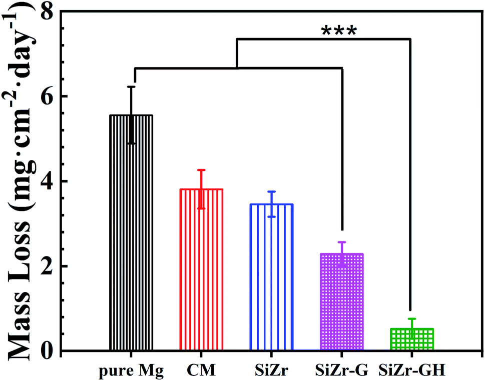 | ||
| Fig. 7 The mass loss of various coatings after exposure to 0.6 M neutral NaCl solution for 28 days (n = 3, ***p < 0.001). | ||
4 Conclusions
In summary, we have designed and synthesized a SiO2-based sol–gel coating by applying low-temperature ring-opening addition reaction as the preparation process. The polymerization of individual clusters under mild hydrolysis and curing conditions results in a compact, continuous and defect-free surface morphology. Especially, the outstanding metallic adhesion nature of the sol–gel coating was not damaged in the modified process. Finally, the sol–gel coating shows excellent corrosion resistant performance, which enables to increase the overall impedance modulus by 27 times than that of the conventional sol–gel coating and decrease the corrosion rate from 3.8 ± 0.5 mg cm−2 per day (commercial chromate conversion coating) to 0.5 ± 0.2 mg cm−2 per day. This strategy opens great perspectives in designing novel and efficient corrosion resistant sol–gel coatings and might shed light on the exploration of powerful protocols to address the limited application problems of magnesium alloys.Conflicts of interest
There are no conflicts to declare.Acknowledgements
The authors are grateful for grants received from the National Natural Science Foundation of China (Grant No. 51875240).References
- S. Tang, T. Xin, W. Xu, D. Miskovic, G. Sha, Z. Quadir, S. Ringer, K. Nomoto, N. Birbilis and M. Ferry, Nat. Commun., 2019, 10, 1–8 CrossRef.
- T. T. T. Trang, J. H. Zhang, J. H. Kim, A. Zargaran, J. H. Hwang, B. C. Suh and N. J. Kim, Nat. Commun., 2018, 9, 1–6 CrossRef CAS.
- P. Xiong, Z. Jia, W. Zhou, J. Yan, P. Wang, W. Yuan, Y. Li, Y. Cheng, Z. Guan and Y. Zheng, Acta Biomater., 2019, 92, 336–350 CrossRef CAS.
- M. Faustini, L. Nicole, E. Ruiz-Hitzky and C. Sanchez, Adv. Func. Mater., 2018, 28, 1704158–1704188 CrossRef.
- E. V. Skorb, D. Fix, D. V. Andreeva, H. Möhwald and D. G. Shchukin, Adv. Func. Mater., 2009, 19, 2373–2379 CrossRef CAS.
- Q. Lei, J. Guo, A. Noureddine, A. Wang, S. Wuttke, C. J. Brinker and W. Zhu, Adv. Func. Mater., 2020, 30, 1909539–1909567 CrossRef CAS.
- K. Wang and J. He, ACS Appl. Mater. Interfaces, 2018, 10, 11189–11196 CrossRef CAS.
- M. L. Zheludkevich, R. Serra, M. F. Montemor, K. A. Yasakau, I. M. M. Salvado and M. G. S. Ferreira, Electrochim. Acta, 2005, 51, 208–217 CrossRef CAS.
- Q. Li, X. Zhong, J. Hu and W. Kang, Prog. Org. Coat., 2008, 63, 222–227 CrossRef CAS.
- N. Li, Y. D. Li, Y. B. Wang, M. Li, Y. Cheng, Y. H. Wu and Y. F. Zheng, Surf. Interface Anal., 2013, 45, 1217–1222 CrossRef CAS.
- W. Xi, T. F. Scott, C. J. Kloxin and C. N. Bowman, Adv. Func. Mater., 2014, 24, 2572–2590 CrossRef CAS.
- W. Shen, Y. Zhang, P. Wan, L. An, P. Zhang, C. Xiao and X. Chen, Adv. Mater., 2020, 32, 2001108–2001117 CrossRef CAS.
- Z. Zhang, C. He, Y. Rong, H. Ren, T. Wang, Z. Zou and X. Chen, Nat. Sci. Rev., 2020, 128–139 CrossRef.
- M. M. Avedesian and H. Baker, ASM specialty handbook: magnesium and magnesium alloys, ASM International, 1999 Search PubMed.
- I. O. F., ISO-2049: Paints and varnishes — Cross-cut test, 2013 Search PubMed.
- I. O. F., ISO-8407: Corrosion of metal and alloys — Removal of corrosion products from corrosion test specimens, 2009 Search PubMed.
- B. Peng and A. Imhof, Soft Matter, 2015, 11, 3589–3598 RSC.
- B. Dyett and R. Lamb, Adv. Mater. Interfaces, 2016, 3, 1500680–1500689 CrossRef.
- N. Li, Y. Chen, B. Deng, J. Yue, W. Qu, H. Yang, Y. He, W. Xia and L. Li, J. Alloys Compd., 2019, 792, 1036–1044 CrossRef CAS.
- A. S. Hamdy, Mater. Lett., 2006, 60, 2633–2637 CrossRef CAS.
- H.-W. Kim, Y.-H. Koh, L.-H. Li, S. Lee and H.-E. Kim, Biomaterials, 2004, 25, 2533–2538 CrossRef.
- D.-M. Liu, Q. Yang and T. Troczynski, Biomaterials, 2002, 23, 691–698 CrossRef CAS.
- H.-W. Kim, Y.-M. Kong, C.-J. Bae, Y.-J. Noh and H.-E. Kim, Biomaterials, 2004, 25, 2919–2926 CrossRef CAS.
- M. L. Zheludkevich, R. Serra, M. F. Montemor, K. A. Yasakau, I. M. M. Salvado and M. G. S. Ferreira, Electrochim. Acta, 2005, 51, 208–217 CrossRef CAS.
- S. H. Messaddeq, S. H. Pulcinelli, C. V. Santilli, A. C. Guastaldi and Y. Messaddeq, J. Non-Cryst. Solids, 1999, 247, 164–170 CrossRef CAS.
- D. Wang and G. P. Bierwagen, Prog. Org. Coat., 2009, 64, 327–338 CrossRef CAS.
- M. Forsyth, P. C. Howlett, S. K. Tan, D. R. MacFarlane and N. Birbilis, Electrochem. Solid-State Lett., 2006, 9, B52–B55 CrossRef CAS.
- N. T. Kirkland, T. Schiller, N. Medhekar and N. Birbilis, Corros. Sci., 2012, 56, 1–4 CrossRef CAS.
- C. Ke, Y. J. Wu, Y. Qiu, J. H. Duan, N. Birbilis and X. B. Chen, Corros. Sci., 2016, 113, 145–159 CrossRef CAS.
- G. Q. Duan, L. X. Yang, S. J. Liao, C. Y. Zhang, X. P. Lu, Y. E. Yang, B. Zhang, Y. Wei, T. Zhang, B. X. Yu, X. C. Zhang and F. H. Wang, Corros. Sci., 2018, 135, 197–206 CrossRef CAS.
- Z. Chunyan, L. Shangju, Y. Baoxing, L. Xiaopeng, C. Xiao-Bo, Z. Tao and W. Fuhui, Corros. Sci., 2019, 150, 279–295 CrossRef.
- X. Lu, Y. Li, P. Ju, Y. Chen, J. Yang, K. Qian, T. Zhang and F. Wang, Corros. Sci., 2019, 148, 264–271 CrossRef CAS.
- G. Wu, X. Zhang, Y. Zhao, J. M. Ibrahim, G. Yuan and P. K. Chu, Corros. Sci., 2014, 78, 121–129 CrossRef CAS.
- M. A. Shaik, K. H. Syed and B. R. Golla, Corros. Sci., 2019, 153, 249–257 CrossRef CAS.
- H. Qian, D. Xu, C. Du, D. Zhang, X. Li, L. Huang, L. Deng, Y. Tu, J. M. Mol and H. A. Terryn, J. Mater. Chem. A, 2017, 5, 2355–2364 RSC.
- Q. Hou, Z. Liu, C. Li and X. Li, Corros. Sci., 2017, 128, 154–163 CrossRef CAS.
Footnote |
| † Electronic supplementary information (ESI) available. See DOI: 10.1039/d0ra09408k |
| This journal is © The Royal Society of Chemistry 2021 |