 Open Access Article
Creative Commons Attribution 3.0 Unported Licence
Intrinsic asymmetric ferroelectricity induced giant electroresistance in ZnO/BaTiO3 superlattice
Ye Yuana,
Yue-Wen Fang b,
Yi-Feng Zhaoa and
Chun-Gang Duan
 *ac
*ac
aState Key Laboratory of Precision Spectroscopy, Key Laboratory of Polar Materials and Devices, Ministry of Education, Department of Electronics, East China Normal University, Shanghai, 200241, China
bLaboratory for Materials and Structures & World Research Hub Initiative, Institute of Innovative Research, Tokyo Institute of Technology, 4259 Nagatsuta, Midori, Yokohama, 226-8503, Japan
cCollaborative Innovation Center of Extreme Optics, Shanxi University, Taiyuan, Shanxi 030006, China. E-mail: cgduan@clpm.ecnu.edu.cn
First published on 11th January 2021
Abstract
Here, we combine the piezoelectric wurtzite ZnO and the ferroelectric (111) BaTiO3 as a hexagonal closed-packed structure and report a systematic theoretical study on the ferroelectric behavior induced by the interface of ZnO/BaTiO3 films and the transport properties between the SrRuO3 electrodes. The parallel and antiparallel polarizations of ZnO and BaTiO3 can lead to intrinsic asymmetric ferroelectricity in the ZnO/BaTiO3 superlattice. Using first-principles calculations we demonstrate four different configurations for the ZnO/BaTiO3/ZnO superlattice with respective terminations and find one most favorable for the stable existence of asymmetric ferroelectricity in thin films with thickness less than 4 nm. Combining density functional theory calculations with non equilibrium Green's function formalism, we investigate the electron transport properties of SrRuO3/ZnO/BaTiO3/ZnO/SrRuO3 FTJ and SrRuO3/ZnO/BaTiO3/SrRuO3 FTJ, and reveal a high TER effect of 581% and 112% respectively. These findings provide an important insight into the understanding of how the interface affects the polarization in the ZnO/BaTiO3 superlattice and may suggest a controllable and unambiguous way to build ferroelectric and multiferroic tunnel junctions.
Introduction
The past decades have witnessed an explosion in the design of ferroelectric tunnel junctions (FTJs) with the aim of accelerating their commercial applications into nonvolatile information devices.1–13 Switching the ferroelectric polarization gives rise to a dramatic change of the tunneling electroresistance (i.e., TER effect),10 making it possible to nondestructively read out the polarization state that carries information. Incorporating ferroelectric and piezoelectric components could help to construct a ferroelectric tunnel junction and show a TER effect.14–17 Coupling between the piezoelectric ZnO and the ferroelectric BaTiO3 may cause bistable ferroelectric polarization orientation.18–22 The piezoelectric ZnO has an inherent polarization which is difficult to reverse using an electric field, but the polarization of ferroelectric BaTiO3 can be reversed in experiments. The parallel or antiparallel polarizations of ZnO and BaTiO3 may lead to intrinsic asymmetric ferroelectricity in the ZnO/BaTiO3 superlattice which is similar to that found in tricolor superlattices.23 However, there are few studies on the transport properties of ZnO/BaTiO3 heterostructures both in theory and experiment. In addition, BaTiO3 can be stacked along the [111] direction24–26 and can provide corrugated honeycomb interfaces which can stack closely with wurtzite ZnO. This stacking may make FTJs based on ZnO/BaTiO3 thinner than those currently available. The research of ZnO/BaTiO3 heterostructure which combined wurtzite ZnO and (111) BaTiO3 is relatively few.20,21 The theoretical research is needed to reveal its atomic scale of interfaces and transport properties.In this paper, the piezoelectric wurtzite ZnO and the ferroelectric perovskite (111) BaTiO3 are closed-packed with good match of the lattice constants in all the theoretical study. We consider four configurations with respective terminations and show a systematic research on the orientation of polarization induced by the interface of ZnO/BaTiO3/ZnO films using first-principles calculations. After comparing the four configurations, we choose one configuration which is most favorable for the stable existence of asymmetric ferroelectricity in thin films to study its transport properties. The thickness of this ZnO/BaTiO3 film is less than 4 nm. Combining density functional theory calculations with non equilibrium Green's function formalism, we investigate the electron transport properties of SrRuO3/ZnO/BaTiO3/ZnO/SrRuO3 and SrRuO3/ZnO/BaTiO3/SrRuO3 with a giant TER effect of 581% and 112% respectively. Compared to the previous results,27–31 the TER effect of 581% for the tunnel junction combined ZnO and (111) BaTiO3 in this article is larger than the highest TER effect of 400%31 for the previous BaTiO3-based tunnel junctions. The junctions combined ZnO and (111) BaTiO3 may exhibit richer and more novel properties in the future. These findings provide an important insight into the understanding of how the interface affect the polarization in ZnO/BaTiO3 superlattice and may suggest a controllable and unambiguous way to build ferroelectric and multiferroic tunnel junctions.
Method of calculation
The geometry optimizations and electronic structure calculations of all models are performed within density functional theory (DFT) calculations by using the projector augmented wave (PAW) method as implemented in the Vienna ab initio simulation package (VASP).32–34 The exchange–correlation potential is treated in the generalized gradient approximation (GGA) of Perdew, Burke, and Ernzerhof (PBE).35 We use the energy cutoff of 500 eV for the plane wave expansion of the PAWs. A 6 × 6 × 1 Γ centered grid for k-point sampling is adopted for supercells in the self-consistent calculations. The Brillouin zone integrations are calculated using the tetrahedron method with Blöchl corrections.36 In the structural relaxations, the atomic geometries were fully optimized until the Hellmann–Feynman forces were less than 1 meV Å−1.The device properties of the FTJ are calculated by using density functional theory plus non equilibrium Green's function formalism (DFT + NEGF approach)37,38 as implemented in the Atomistix ToolKit-Virtual NanoLab (ATK-VNL) software package.39 The double-ζ plus polarization basis set is employed, and a real-space mesh cutoff energy of 80 Hartree is used to guarantee the good convergence of the device configuration. The electron temperature is set at 300 K. The 5 × 5 × 101 k mesh is used for the self-consistent calculations to eliminate the mismatch of Fermi level between electrodes and the central region. The 35 × 35 k mesh is adopted during the calculations of transmission spectra. The screening effect is considered by building screening region consist of electrode extension region and surface region.
Results and discussion
The cubic BaTiO3 stacking along the [111] direction has a hexagonal-like structure, where the transition metal Ti ions form the graphene-like buckled honeycomb lattice (see Fig. 1). The [111] direction in the bulk structures corresponds to the z direction. The theoretical lattice constant we calculated for the cubic phase of BaTiO3 is 4.036 Å with PBE method, and the distance between two adjacent Ti atoms in one atomic layer in the (111)-plane is 5.707 Å. The wurtzite ZnO has a hexagonal structure with theoretical in-plane lattice constant of 3.299 Å, and the distance between two adjacent Zn atoms of the honeycomb in superlattice is 5.714 Å. Hence, the (111) BaTiO3 and wurtzite ZnO have a very good match of the lattice constants (a mismatch is only about 0.1%) that allows layer-by-layer epitaxial growth of ZnO/BaTiO3 (111) multilayers with no misfit dislocation.
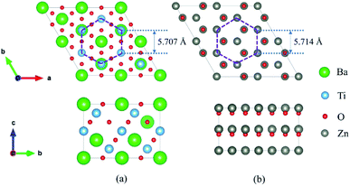 | ||
Fig. 1 Geometry for (a) perovskite BaTiO3 stacking along the [111] direction and (b) a  supercell of wurtzite ZnO. supercell of wurtzite ZnO. | ||
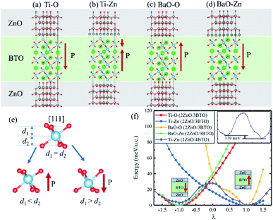
We calculated ZnO/BaTiO3/ZnO supercell composed of two layers of ZnO and three layers of BaTiO3 (BTO). Four different configurations of the ZnO/BaTiO3/ZnO heterostructure were considered, with the respective terminations of Ti–O (Fig. 2(a)), Ti–Zn (Fig. 2(b)), BaO–O (Fig. 2(c)) and BaO–Zn (Fig. 2(d)). The direction of polarization of BaTiO3 was adjusted to the [111] direction under the influence of the interface and can be obtained by analyzing the relative Ti–O displacements along the [111] direction, see Fig. 2(e). The three O atoms at the top of the octahedron are on the same plane, and their vertical distance from Ti atom is d1. Similarly, d2 is the vertical distance from three O atoms at the bottom of the octahedron to Ti atom. Therefore, the ferroelectric polarization is up when d1 < d2, and is down when d1 > d2. Using this way, the polarization P in the four different configurations were determined, as indicated by the red arrows in Fig. 2(a–d). As shown in Fig. 2(a), the first kind of terminations of the interfaces is Ti–O, means the atomic layer of Ti in (111) BaTiO3 contact with O layer in ZnO. This configuration make BaTiO3 has a polarization pointing from top to bottom, and the polarization is very robust. The single well potential in Fig. 2(f) denotes the polarization is almost impossible to reverse. The second configuration is Ti–Zn, means the Ti layer in (111) BaTiO3 contact with Zn layer in ZnO. This kind of configuration make the interior polar displacements of BaTiO3 near the top interface have opposite orientation with that near the bottom interface, and the net polarization is pointing up. The naming rules for the other two configurations are the same as above. When we increase the thickness of BaTiO3 and decrease the thickness of ZnO for the Ti–Zn configuration, a double-well profile is observed in Fig. 2(f) which is a general feature of ferroelectric materials. From these results, we concluded that the Ti–Zn configuration may implement reversible FTJ relatively easier in thicker BaTiO3.
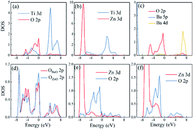
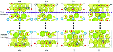
Different interfaces between BaTiO3 and ZnO can induce to different polarizations of BaTiO3 near the interfaces. The reason for it in Ti–O configuration lies in the different vertical distance between Ti and O atoms at top and bottom interfaces. The Ti atoms from BaTiO3 and O atoms from ZnO are bonding in the interfaces as shown in Fig. 3(a). In the top interface, the O atoms is directly above the nearest neighbour Ti atoms, and the bond length is about 1.93 Å. However, in the bottom interface, the O atoms lies diagonally below the Ti atoms, so the vertical distance between Ti and O atoms is small although the bond length is 1.85 Å. The difference of Ti–O bonding between top interface and bottom interface can be clarified in Fig. 4(a) and (b). This asymmetry in top and bottom interfaces causes the center of positive charge to move downward. That is why the polarization is from the top interface to the bottom interface in Ti–O configuration. In Ti–Zn configuration, the Ti atoms and Zn atoms are both positive ions, the orbital projected density of states show that the overlapping between these two transition metal ions are very few. The Coulomb repulsion play a dominant role here. That is why the BaTiO3 near top interface and bottom interface have different polarizations. Fig. 3(c) and (d) show the situation of both top interface and bottom interface in BaO–O configuration. The results denote that the Ba atoms from BaTiO3 and O atoms from ZnO in top interface cannot bond because there is no overlapping between their density of states. However, the O atoms from BaTiO3 and O atoms from ZnO can form covalent bonds as shown in Fig. 3(d). Therefore, the center of negative charge moves downward, results in the polarization of BaTiO3 in BaO–O configuration from bottom interface to top interface. In the BaO–Zn configuration, the O atoms from BaTiO3 and Zn atoms from ZnO in both top interface and bottom interface are bonding, but the bond in top interface is stronger. As shown in Fig. 3(e) and (f), the Zn 3d orbital and O 2p orbital in top interface have overlapping from −6 eV to 0 eV, and the overlapping in bottom interface is only from −4 eV to −1 eV. Therefore, the polarization of BaTiO3 for BaO–Zn configuration is from top interface to bottom interface.
The more intuitive results are shown in Fig. 4(a)–(h). All the graphical charge densities have the same isosurface. It is clear that the Ti atoms from BaTiO3 and O atoms from ZnO are bonding in both top and bottom interfaces for Ti–O configuration, but the vertical lengths in bottom interface are shorter. The Ti atoms and Zn atoms in Ti–Zn configuration cannot bond and so do the Ba atoms and O atoms in BaO–O configuration. The bonds of O atoms and Zn atoms in top interface are stronger than that in bottom interface. The results of these charge densities are consistent with the above analysis based on the density of states.
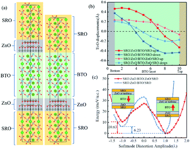
In Fig. 5(a), three layers of SrRuO3 (SRO) were interfaced to the ZnO/BTO/ZnO overlayers to form the SRO/ZnO/BTO/ZnO/SRO and SRO/ZnO/BTO/SRO heterostructures. We define the state which has polarization from bottom interface to top interface as the ‘up’ state and the opposite direction as the ‘down’ state. From the rumpling of the ‘up’ and ‘down’ states in junction structures as shown in Fig. 5(b), we can see that the ferroelectric displacements of both supercells are significantly asymmetric. For the average polarization displacements, the difference between ‘up’ and ‘down’ states are dramatic. Our calculations have found two inequivalent energy minima in each system, as clearly shown in Fig. 5(c). This is the signature of asymmetric ferroelectricity. Note that here the energy profiles are obtained by simulating the soft mode distortion of the BaTiO3 layer (characterized by the parameter λ), where we choose states with λ = +1 to be the lowest energy states (‘up’ states) and states with λ = −1 to be the metastable energy states (‘down’ states) for both two supercells. The coordinates of other λ states are linear interpolations (|λ| < 1) or extrapolations (|λ| > 1) between the coordinates of ‘up’ and ‘down’ states according to their values. Here, the thickness of ZnO/BaTiO3 superlattice is less than 4 nm, which is thinner than those currently available in experiment.18–22
Essentially speaking, the asymmetric ferroelectricity of ZnO/BaTiO3 superlattice comes from the relative orientations of polarizations of ZnO and BaTiO3 in supercells. When the orientations of the polarization of ZnO and BaTiO3 are opposite, the counteraction of the intensity of total polarization is appeared. This will result in a low conductance. The high conductance comes from the enhancement of total polarization resulting from the same orientations of the polarization of ZnO and BaTiO3. Fig. 6 shows schematically the two conductance levels indicating the possibility of switching between them by electric (E) fields.
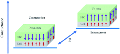 | ||
| Fig. 6 Conductance of the SrRuO3/ZnO/BaTiO3/SrRuO3 FTJ. The two conductance states are distinguished by polarization of BaTiO3. | ||
To evaluate the performance of SRO/ZnO/BTO/ZnO/SRO and SRO/ZnO/BTO/SRO FTJs, density functional theory plus non equilibrium Green's function formalism is used to study the electrical conductance and TER effect. In our calculations, the transmission coefficients and reflection matrices are determined by matching the wave functions of the scattering region with linear combinations of propagating Bloch states in the electrodes. Because the electronic states at the EF dominate the transport properties, the zero-bias electrical conductance within the Landauer−Büttiker formula can be evaluated as
 | (1) |
 | (2) |
As a result, the reversal of ferroelectric polarization in the SRO/ZnO/BTO/ZnO/SRO FTJ leads to a significantly enhanced TER effect at zero bias, which is approximately about 581%. The TER effect for SRO/ZnO/BTO/SRO FTJ is 112%, which is also tremendous.
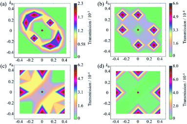
To understand the change in the conductance ratio during the polarization reversal, the k‖-resolved transmissions at EF are shown in Fig. 7. In the up state of SRO/ZnO/BTO/ZnO/SRO FTJ, the transmission coming from the rhombus regions of the 2D Brillouin zone are largest, indicating the feature of resonant tunneling. We find the transmission eigenstates around this region show much smaller decay rate than those around Γ point, which is responsible for the significant transmission. The reason is that the amplitude of transmission eigenstates for this region is much larger than that for Γ point, which indicates greater transmission probability. Compared to the up state, the transmission in the down state is largely reduced, leading to lower conductance than the up state. This explains the observed giant TER effect in the SRO/ZnO/BTO/ZnO/SRO and SRO/ZnO/BTO/SRO FTJ.
Conclusions
In conclusion, the four stacking configurations of ZnO/BTO/ZnO supercell with two layers of ZnO and three layers of (111) BTO have been studied using DFT calculations. The mechanism of polarization direction in (111) BTO influenced by the interfaces are investigated. Combining density functional theory calculations with non equilibrium Green's function formalism, two giant TER effects of 581% and 112% are observed in our newly designed SRO/ZnO/BTO/ZnO/SRO and SRO/ZnO/BTO/SRO FTJ heterostructure. The thickness of ZnO/BTO in this heterostructure is less than 4 nm. The proposed strategy in our study is applicable to design higher performance FTJs. We hope this work will stimulate the experimental endeavors of fabricating FTJs with a giant TER effect to accelerate their commercial applications into ultralow-power, high-speed, and nonvolatile nanoscale memory devices.Conflicts of interest
There are no conflicts to declare.Acknowledgements
This work was supported by the National Key Research and Development Program of China (2017YFA0303403), Shanghai Science and Technology Innovation Action Plan (No. 19JC1416700), the NSF of China 11774092, ECNU Multifunctional Platform for Innovation.References
- W. Huang, Y. W. Fang, Y. Yin, B. Tian, W. Zhao, C. Hou, C. Ma, Q. Li, E. Y. Tsymbal, C. G. Duan and X. Li, ACS Appl. Mater. Interfaces, 2018, 10, 5649–5656 CrossRef CAS.
- S. Boyn, J. Grollier, G. Lecerf, B. Xu, N. Locatelli, S. Fusil, S. Girod, C. Carretero, K. Garcia, S. Xavier, J. Tomas, L. Bellaiche, M. Bibes, A. Barthelemy, S. Saighi and V. Garcia, Nat. Commun., 2017, 8, 14736 CrossRef CAS.
- L. W. Martin and A. M. Rappe, Nat. Rev. Mater., 2017, 2, 16087 CrossRef CAS.
- W. Jin Hu, Z. Wang, W. Yu and T. Wu, Nat. Commun., 2016, 7, 10808 CrossRef.
- X. W. Shen, Y. W. Fang, B. B. Tian and C. G. Duan, ACS Appl. Electron. Mater., 2019, 1, 1133–1140 CrossRef CAS.
- C. Lu, W. Hu, Y. Tian and T. Wu, Appl. Phys. Rev., 2015, 2, 021304 Search PubMed.
- A. Chanthbouala, V. Garcia, R. O. Cherifi, K. Bouzehouane, S. Fusil, X. Moya, S. Xavier, H. Yamada, C. Deranlot, N. D. Mathur, M. Bibes, A. Barthelemy and J. Grollier, Nat. Mater., 2012, 11, 860–864 CrossRef CAS.
- V. Garcia, M. Bibes, L. Bocher, S. Valencia, F. Kronast, A. Crassous, X. Moya, S. Enouz-Vedrenne, A. Gloter, D. Imhoff, C. Deranlot, N. D. Mathur, S. Fusil, K. Bouzehouane and A. Barthelemy, Science, 2010, 327, 1106–1110 CrossRef CAS.
- V. Garcia, S. Fusil, K. Bouzehouane, S. Enouz-Vedrenne, N. D. Mathur, A. Barthelemy and M. Bibes, Nature, 2009, 460, 81–84 CrossRef CAS.
- M. Y. Zhuravlev, R. F. Sabirianov, S. S. Jaswal and E. Y. Tsymbal, Phys. Rev. Lett., 2005, 94, 246802 CrossRef.
- E. Y. Tsymbal and H. Kohlstedt, Science, 2006, 313, 181–183 CrossRef CAS.
- J. P. Velev, C. G. Duan, K. D. Belashchenko, S. S. Jaswal and E. Y. Tsymbal, Phys. Rev. Lett., 2007, 98, 137201 CrossRef CAS.
- J. F. Scott, Nat. Mater., 2007, 6, 256–257 CrossRef CAS.
- S. Yuan, J. Wang, X. Zhong, F. Wang, B. Li and Y. Zhou, J. Mater. Chem. C, 2013, 1, 418–421 RSC.
- H. Kohlstedt, N. A. Pertsev, J. Rodríguez Contreras and R. Waser, Phys. Rev. B: Condens. Matter Mater. Phys., 2005, 72 CrossRef CAS.
- X. Lu, W. Cao, W. Jiang and H. Li, J. Appl. Phys., 2012, 111, 014103 CrossRef.
- Y. Zheng and C. H. Woo, Nanotechnology, 2009, 20, 075401 CrossRef.
- C. Jia, X. Yin, G. Yang, Y. Wu, J. Li, Y. Chen and W. Zhang, Appl. Phys. Lett., 2017, 111, 113506 CrossRef.
- R. Aepuru, S. Kankash and H. S. Panda, RSC Adv., 2016, 6, 32272–32285 RSC.
- V. M. Voora, T. Hofmann, M. Brandt, M. Lorenz, N. Ashkenov, M. Grundmann and M. Schubert, Appl. Phys. Lett., 2009, 95, 082902 CrossRef.
- V. M. Voora, T. Hofmann, M. Schubert, M. Brandt, M. Lorenz, M. Grundmann, N. Ashkenov and M. Schubert, Appl. Phys. Lett., 2009, 94, 142904 CrossRef.
- K. C. Sekhar, J. P. B. Silva, K. Kamakshi, M. Pereira and M. J. M. Gomes, Appl. Phys. Lett., 2013, 102, 212903 CrossRef.
- Y. C. Gao, C. G. Duan, X. D. Tang, Z. G. Hu, P. Yang, Z. Zhu and J. Chu, J. Phys.: Condens. Matter, 2013, 25, 165901 CrossRef.
- T. Watanabe, M. Shimada, T. Aiba, H. Yabuta, K. Miura, K. Oka, M. Azuma, S. Wada and N. Kumada, Jpn. J. Appl. Phys., 2011, 50, 09ND01 CrossRef.
- A. Raeliarijaona and H. Fu, J. Appl. Phys., 2014, 115, 054105 CrossRef.
- O. Eibl, P. Pongratz, P. Skalicky and H. Schmelz, J. Am. Ceram. Soc., 1987, 70, C-195–C-197 CrossRef.
- M. D. Qian, I. Fina, F. Sanchez and J. Fontcuberta, Adv. Electron. Mater., 2019, 5, 1800407 CrossRef.
- M. Qian, I. Fina, F. Sánchez and J. Fontcuberta, Small, 2019, 15, 1805042 CrossRef.
- M. Abuwasib, H. Lee, J.-w. Lee, C.-B. Eom, A. Gruverman and U. Singisetti, IEEE Trans. Electron Devices, 2019, 66, 2186–2191 CAS.
- N. V. Andreeva, A. A. Petrov, A. Petraru, A. E. Petukhov and A. G. Rybkin, Mater. Res. Express, 2018, 6, 026427 CrossRef.
- C. Li, L. Huang, T. Li, W. Lü, X. Qiu, Z. Huang, Z. Liu, S. Zeng, R. Guo, Y. Zhao, K. Zeng, M. Coey, J. Chen, A. Ariando and T. Venkatesan, Nano Lett., 2015, 15, 2568–2573 CrossRef CAS.
- G. Kresse and J. Furthmuller, Comput. Mater. Sci., 1996, 6, 15–50 CrossRef CAS.
- G. Kresse and J. Furthmuller, Phys. Rev. B: Condens. Matter Mater. Phys., 1996, 54, 11169–11186 CrossRef CAS.
- G. Kresse and D. Joubert, Phys. Rev. B: Condens. Matter Mater. Phys., 1999, 59, 1758–1775 CrossRef CAS.
- J. P. Perdew, K. Burke and M. Ernzerhof, Phys. Rev. Lett., 1996, 77, 3865–3868 CrossRef CAS.
- P. E. Blochl, O. Jepsen and O. K. Andersen, Phys. Rev. B: Condens. Matter Mater. Phys., 1994, 49, 16223–16233 CrossRef CAS.
- J. Taylor, H. Guo and J. Wang, Phys. Rev. B: Condens. Matter Mater. Phys., 2001, 63, 245407 CrossRef.
- M. Brandbyge, J.-L. Mozos, P. Ordejón, J. Taylor and K. Stokbro, Phys. Rev. B: Condens. Matter Mater. Phys., 2002, 65, 165401 CrossRef.
- Atomistix ToolKit version 2014.3-Virtual NanoLab version 2017.2, QuantumWise A/S, https://www.quantumwise.com Search PubMed.
- J. P. Velev, C. G. Duan, J. D. Burton, A. Smogunov, M. K. Niranjan, E. Tosatti, S. S. Jaswal and E. Y. Tsymbal, Nano Lett., 2009, 9, 427–432 CrossRef CAS.
| This journal is © The Royal Society of Chemistry 2021 |

