DOI:
10.1039/D0RA08229E
(Paper)
RSC Adv., 2021,
11, 1303-1319
Tuning of structural and optical properties with enhanced catalytic activity in chemically synthesized Co-doped MoS2 nanosheets†
Received
25th September 2020
, Accepted 16th November 2020
First published on 5th January 2021
Abstract
Molybdenum disulfide (MoS2) nanosheets, due to having a highly active nature, being low cost and having unique physical and chemical properties, have shown their efficacy in the catalytic reduction of nitroarenes. Doping of transition metal ions in molybdenum disulfide (MoS2) nanosheets is a well-known strategy to enhance their catalytic efficiency for the reduction of nitroarenes, however, finding the optimum dopant amount is still a subject of ongoing research. Herein, we have synthesized few-layered cobalt (Co) doped MoS2 nanosheets with different cobalt content (2%, 4%, 6% and 8%) through the solvothermal approach, taking sodium molybdate dihydrate (Na2MoO4·2H2O), thiourea (CH4N2S) and cobalt acetate tetrahydrate [Co(CH3COO)2·4H2O] as precursors and their catalytic performance has been affirmed by monitoring the reduction of p-nitrophenol by NaBH4 in real time using UV-visible absorption spectroscopy. The 6% Co doped MoS2 nanosheets have exhibited superior catalytic activity with a pseudo-first order rate constant of 3.03 × 10⁻³ s−1 attributed to the abundant defects in the active edge sites having a dominant metallic 1T phase with Co ion activated defective basal planes, sulphur (S) edges, synergistic structural and electronic modulation between MoS2 and Co ions and enhanced electron transfer assisted through redox cycling in the active sites. An attempt has also been made to study the manipulation of structural and optical properties with cobalt doping in MoS2 nanosheets to establish a correlation between the catalytic efficiency and dopant content. This study demonstrates that proper tuning of Co doping in MoS2 nanosheets paves the way in searching for a potential alternative of a noble metal catalyst for the catalytic reduction of nitroarenes.
1. Introduction
Graphene-like two-dimensional (2D) transition metal dichalcogenides1 (TMDs) have garnered a lot of interest because of their fascinating structural and electronic properties which make them suitable as catalysts in various technologically important applications such as electrochemical generation of hydrogen from water2–4 and hydro-desulfurization of petroleum.5,6 One of the most widely studied TMD systems includes layered MoS2. It is commonly known to exist in two crystallographic forms: (i) the thermodynamically stable trigonal prismatic (2H) phase (space group P63/mmc)7 and (ii) the metastable octahedral (1T) phase (space group P3m1).8 Among these 1T MoS2 is reported to show metallic behaviour9 whereas the 2H MoS2 is an indirect semiconductor having a band gap of ∼1.2 eV.10 The electronic properties of 2H MoS2 can be tailored by changing the layer thickness,10 doping of TM metal ions11 and introducing tensile lattice strain.12 Theoretical and experimental studies indicate that the catalytic activity of thermodynamically stable 2H polymorph of MoS2 is associated with its metallic edges, whereas its semiconducting basal plane is proved to be catalytically inert.2,4
p-Nitrophenol (p-NP) is one of the most common and stubborn harmful organic pollutants found in industrial wastewaters. However, its reductive derivative, p-aminophenol (p-AP) is widely used in manufacturing of drugs such as paracetamol and clofibrate and also used as a developing agent in photography and as a petroleum additives.13–15 Therefore, the catalytic transformation of p-NP into p-AP has been extensively studied as a model reaction to verify the activity of a catalyst during the past few years.16–18 Most of these studies were focused on the activity of noble-metal nanoparticles (NPs) such as Ag, Au, Pd and Pt. Although they possess high catalytic potential, however, their usage may lead to depletion of rare resources, environmental contamination and health issues. In addition, the agglomeration of colloidal noble metal NPs during the catalytic reaction is often inevitable.
In this regard, MoS2, a 2D layered material, acts as an efficient candidate in catalytic reduction of p-NP as its basal plane and catalytic edges with increased exposed active sites facilitate the electron transfer process.19 Recently, various nanostructures of MoS2, amorphous20–22/crystalline23–26 and vertically aligned structures27,28 have been explored to maximize the number of active edge sites. Hybridization of MoS2 with conducting/semiconducting/magnetic materials (graphene28–32/CoSe2 (ref. 33)/CoS34–37/CdS38,39/Fe3O4 (ref. 40)) is able to enhance the catalytic activity through synergistic coupling effects. Metastable, intrinsically metallic, octahedral 1T MoS2 obtained through exfoliation of trigonal prismatic 2H MoS2 has proven to be an excellent catalyst for H2 evolution reactions. The 1T phase facilitates electrode kinetics by increasing the electrical conductivity and proliferation of the catalytic active sites.41–43 Noble metal (Au, Ag, Pd, Pt)-MoS2 nanocomposite has proven to be as efficient catalyst, although such type of synthesis procedure includes controlled reaction condition, stabilizing agent and high cost.44 Introducing transition metal ions (Co, Ni, Fe) into the MoS2 matrix has been the classic route to maximize the catalytic activity of MoS2 as the doped ions alter the electronic properties at the coordinatively unsaturated catalytic S-edges.23,45,46 These strategies have been designed largely to either optimize the density of active edge sites by reducing the dimensions along the z direction or xy direction (nanostructures)47 or increase the conductivity by stabilizing the 1T MoS2 polytype.32,41,42
Introduction of cobalt ion in 2H MoS2 may be a fascinating strategy in doping as it can increase the types and numbers of active sites in the basal planes in addition to edges48,49 along with introduction of 1T phase in 2H phase. It also exhibits ready redox Co2+ ↔ Co3+ switching and can alter the band positions favourably. Intrinsic defects in the form of Mo vacancies and sulphur vacancies as well as extrinsic donor and acceptor defects resulting from doping are used to improve the semiconducting properties generally through band gap reduction by lowering the conduction band, raising the valence band, and/or introducing midgap states. These defects can act as electron and hole traps, which can increase the recombination times and alter the recombination rates resulting enhancement in catalytic efficiency than the pristine one.
One of the standard reactions to test the catalytic action is the reduction of p-NP by NaBH4. Nitrophenol, with aromatic rings associated with H-bonding –NO2 and –OH groups, enables the reduction to be carried out in water making it an environment-friendly reaction. In this work we have investigated in detail the tuning with Co doping on structural, optical properties and catalytic activity in chemically synthesized MoS2 nanosheets having the mixture of both 1T and 2H phases. Attempt has also been made to establish a correlation between its observed optical properties with the catalytic efficiency as the doping concentration of Co is increased in MoS2 nanosheets. This study demonstrates that catalytic efficiency of MoS2 nanosheets can be enhanced with increased amount of cobalt doping percentages (2 at. wt%, 4 at. wt%, 6 at. wt%). As Co-doping percentage is increased in MoS2 nanosheets, the band gap is reduced along with increased active sites which facilitate electron transfer easily resulting exceptional catalytic activity in the reduction of nitrophenol to aminophenol. The observed turnover frequency (TOF) in Co–MoS2 (6 at. wt%) is far superior in comparison with other MoS2 architectures and noble-metal-based catalysts, graphene based nanocomposites etc. reported so far.
2. Experimental details
2.1. Chemicals used
High purity (99.9% purity) chemicals, like sodium molybdate dihydrate (Na2MoO4·2H2O), thiourea (CH4N2S), sodium borohydride (NaBH4), acetic acid (CH3COOH), p-nitrophenol (C6H5NO3), cobalt acetate tetrahydrate (CO(CH3COO)2·4H2O), ethyl alcohol (CH3CH2OH) were procured from Sigma-Aldrich. All the reagents are analytical reagent grade and used without further purification.
2.2. Synthesis of ultra-thin MoS2 nanosheets
Pure and Co doped MoS2 nanoparticles/nanosheets were synthesized in aqueous solution using sodium molybdate dihydrate (Na2MoO4·2H2O), thiourea (CH4N2S) via simple hydrothermal technique in the starting solution mixture. In a typical synthesis, 2 mM of Na2MoO4·2H2O and 5 mM of CH4N2S were dissolved in 40 mL of deionized water and were stirred for 30 minutes to obtain the clear starting solution mixture. The pH of the solution mixture was maintained at 5.0 by adding 0.02 mol L−1 of acetic acid (CH3COOH) solution under stirring. This solution mixture was then transferred to a 50 mL Teflon lined stainless steel autoclave and was subjected to hydrothermal treatment at 200 °C for 24 hours under autogenous pressure. The autoclave was then allowed to cool naturally and the obtained black precipitate was separated through centrifugation for 30 minutes. Then the precipitate was washed thoroughly with ethanol and water several times for removal of surface adsorbed ions and impurities. The final product was dried in oven at 80 °C overnight and used for further characterization.
2.3. Synthesis of cobalt (2 at. wt%, 4 at. wt%, 6 at. wt% and 8 at. wt%) doped MoS2 NSs
For the synthesis of 2 at. wt%, 4 at. wt%, 6 at. wt% and 8 at. wt% Co-doped MoS2 samples, appropriate amount of cobalt acetate tetrahydrate [Co(CH3COO)2·4H2O] aqueous solution was added to the former starting solution mixture and stirred very well prior to hydrothermal treatment at 200 °C for 24 hours. The rest of the procedure of separation, purification and collection of the dried as-synthesized samples was repeated as before (Fig. 1).
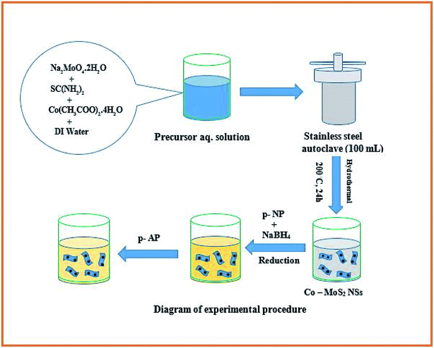 |
| | Fig. 1 Diagram of experimental procedure. | |
2.4. Characterization of nanostructures
The crystalline phase of respective as-synthesized undoped and Co doped MoS2 samples were ascertained through powder X-ray diffraction (XRD) studies. It was carried out employing a Bruker AXS diffractometer D8, Germany using CuKα radiation (λ = 1.5418 Å) at an applied voltage of 40 kV and at a scan rate of 3° min−1 in the 2θ range of 10°–70°. The presence of surface functional groups in the synthesized MoS2 samples were established through Fourier-transformed infrared (FTIR) spectroscopy carried out between 4000 to 400 cm−1 using a Perkin–Elmer Spectrum RX-II Model 73713, USA. The microstructural features of the synthesized MoS2 samples were analyzed by transmission electron microscopy (TEM, FEI-TECNAI G2 20S-TWIN, USA) imaging and high-resolution transmission electron microscopy (HRTEM, JEOL JEM-2100, Japan) imaging at an acceleration voltage of 200 kV. Zeta potential measurement was undertaken to determine the surface charge of the samples using a Malvern Nano ZS instrument. The optical and catalytic activity of the samples was investigated through a Shimadzu-2450 UV-vis-NIR spectrophotometer, Japan. The band gap energies of the samples were evaluated from UV-vis absorption spectra using the Tauc plot. Scanning electron microscopy (SEM) analysis was carried out using a Zeiss, Ultra 55 field emission scanning electron microscope equipped with energy-dispersive X-ray spectroscopy (EDS). The Raman spectra of the samples were recorded on HORIBA Jobin-YvonLabRAM HR800 at 532 nm excitation wavelength.
3. Results and discussion
3.1. Structural study (XRD data analysis)
The room temperature HRXRD (Fig. 2) patterns of undoped and the Co-doped MoS2 nanostructures of different doping concentration were recorded over 2θ range of 10°–70° to verify the formation of crystalline phases of MoS2. The HRXRD data reveals that 2H MoS2 phase is formed having diffraction peaks at 14.2°, 33.4°, 39.7°, 49.7°, 58.8° (PDF 65-1951). It is clearly seen that the crystalline quality is improved with doping of maximum percentages of cobalt. The broadening of peaks has been observed with increase of Co doping concentration due to appearance of lattice strain. Since the ionic radius of Co2+ (0.074 nm) is slightly larger than that of Mo4+ (0.065 nm), it is expected to develop a lattice strain. The crystallite sizes of the MoS2 nanostructures were estimated by Scherrer formula.
Dhkl = kλ/(βhkl![[thin space (1/6-em)]](https://www.rsc.org/images/entities/char_2009.gif) cosθ) cosθ) |
Here, k is a coefficient (k = 0.9), β is the full width at half maximum of the (002) peak, and λ is the incident X-ray wavelength (λ = 0.154 nm). The crystallite sizes D of the undoped and the 8% Co doped MoS2 samples are estimated to be 8.11 nm and 7.44 nm, respectively. The microstrain (ε) and dislocation density (δ) appearing in the lattice due to some substitution of Mo atoms by Co atoms can be calculated from the following relations:
| ε = βcosθ/4, δ = 1/D2 |
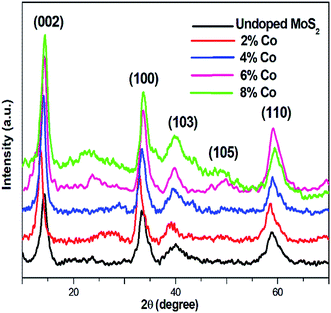 |
| | Fig. 2 XRD pattern of undoped and Co doped MoS2. | |
The values of crystallite size, microstrain and dislocation density are calculated and summarized in Table 1.
Table 1 The microstructural parameters of the undoped and Co doped MoS2 nanostructures
| Co doping percentages |
Crystallite size (nm) |
Microstrain ε |
Dislocation density δ (lines per m2) |
| 0% |
8.11 |
3.98 × 10⁻³ |
1.52 × 10¹⁶ |
| 8% |
7.44 |
5.17 × 10⁻³ |
1.81 × 10¹⁶ |
3.2. Raman spectroscopy study
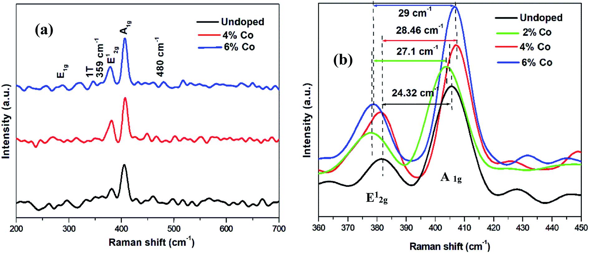
The recorded Raman spectra of MoS2 and Co doped MoS2 are shown in Fig. 3(a). The characteristic peaks at 282, 380, 406 and 458 cm−1 correspond to the E1g, E12g, A1g, and A2u phonon modes of 2H-MoS2. The peak arising due to 1 T-phase of MoS2 is identified at 345 cm−1 (ref. 50) suggesting that the as-synthesized flower-like MoS2 consists of mixed 2H and 1T phases. 18% incorporation of 1T phase in undoped sample and 73% incorporation of 1T phase in 6% Co doped MoS2 samples were obtained. In addition to these peaks, two new peaks emerge at 359 cm−1 and 480 cm−1 for Co2+ doped MoS2 nanostructures. Furthermore, the peak intensity is generally higher with higher doping concentration.51 This suggests that these peaks may belong to the local vibrational modes associated with the Co2+ dopants.
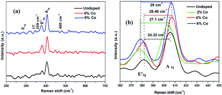 |
| | Fig. 3 (a) Raman spectra for undoped and Co doped MoS2 (b) zoomed view. | |
It is clearly observed that with increase in cobalt doping, E12g vibration mode is decreased, while the A1g vibration mode is increased, which are related to the tensile strain52 appearing in the lattice due to doping of cobalt ion in Mo site and number of layer in MoS2.53 When the layer number increases, the interlayer van der Waals force in MoS2 suppresses atomic vibration, resulting in higher force constants resulting in stiffening of A1g mode (blue-shift). On the contrary, E12g peak shows a red-shift, instead of a blue-shift, suggesting that the increased interlayer van der Waals force plays a minor role while stacking-induced structure changes or long-range coulombic interlayer interactions in multilayer MoS2 may dominate the change of atomic vibration.54 Additionally, the intensity ratio of A1g to E12g mode is 2.17 which concludes that it favours the vibration of A1g mode and thus the best edge-terminated structure.55 According to the dependence of A1g full width at half maximum (FWHM) on the MoS2 thickness, this decrease in FWHM in 6% Co doped MoS2 is an indication of thinning down the effective MoS2 thickness.50 The positions of the characteristic Raman E12g and A1g peaks and their separations with varying cobalt doping concentrations are summarized in Table 2.
Table 2 Comparison of characteristic Raman peak position with varying doping concentration of cobalt ions in MoS2
| Co doping percentages |
E12g (cm−1) |
A1g (cm−1) |
Δk (cm−1) |
| 0% |
381.45 |
405.77 |
24.32 |
| 2% |
379.49 |
406.59 |
27.10 |
| 4% |
378.63 |
407.09 |
28.46 |
| 6% |
378.23 |
407.23 |
29.00 |
3.3. Morphology and microstructure
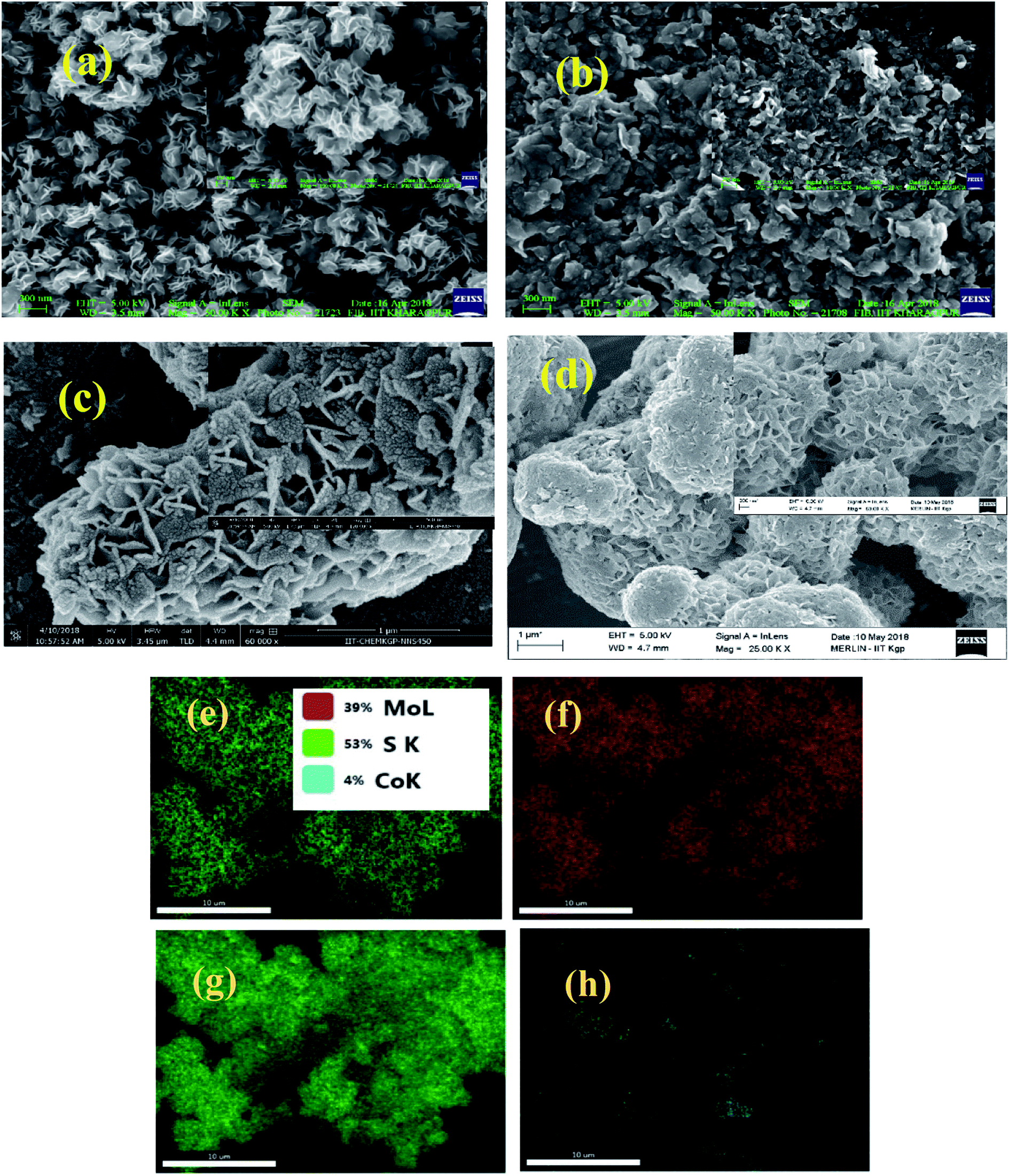
SEM image analysis. The observed surface morphology of the as-prepared samples was analyzed based on recorded SEM and TEM images. As shown in Fig. 4(a), the pristine MoS2 exhibits dispersed nanosheet like morphology. Fig. (b)–(d) show the nanostructures of 2%, 4% and 6% Co doped MoS2 samples. With the incorporation of dopant ion, the dispersed flakes are interlaced by rolling up of surface edges. They form nano-flowers by summing up of nano-flakes (thickness within 10 nm). From EDX analysis of 4% cobalt doped MoS2 it can be seen that S:Mo atomic ratio is 1.4:1. It indicates that some oxygen vacancies are created along with doping. It also shows accurate detection of the amount of cobalt doped in the sample.
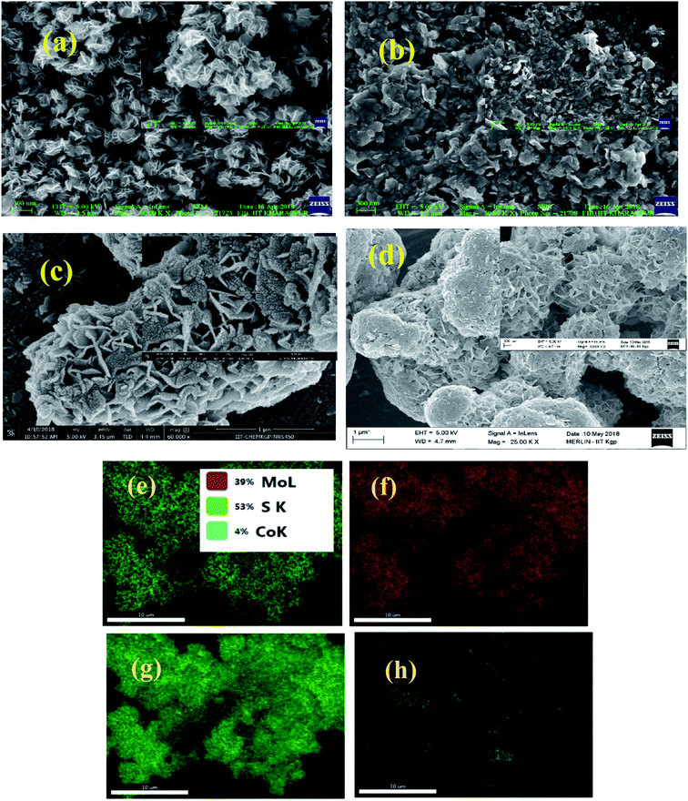 |
| | Fig. 4 SEM images of (a) undoped (b) 2% Co, (c) 4% Co and (d) 6% Co doped MoS2 nanostructures (e) EDS elemental mapping of Mo, S and Co components for 4% Co doped MoS2 (f) Mo, (g) S, (h) Co EDAX mapping for 4% Co doped MoS2. | |
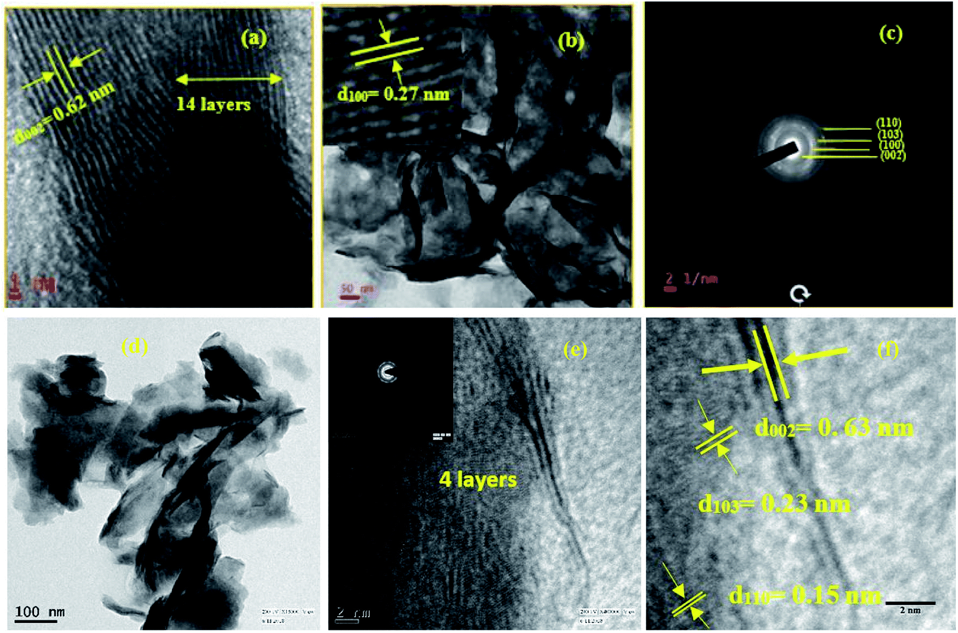
HRTEM image analysis. Fig. 5 shows detailed microstructure of the MoS2 nanosheet samples recorded by using HRTEM imaging. Fig. 5(a) clearly shows the magnified image of interlaced flakes of undoped MoS2 where interlayer distance is found to be 0.62 nm forming a 14 layer system. Inset of Fig. 5(b) shows the interplanar distance between (100) planes and it is found to be 0.27 nm, which matches very well with SAED ring pattern corresponding to (100) plane as shown in Fig. 5(c). The undoped MoS2 reveals polycrystalline nature which is clear from SAED pattern and four distinct rings appears corresponding to planes (002), (100), (103) and (110) which are also seen in XRD pattern. Similar results can also be obtained from Fig. 5(f) of 6% Co doped MoS2. Lattice spacing for (002), (110), (103) planes are 0.63 nm, 0.15 nm and 0.23 nm, respectively. It exactly matches with results obtained from SAED pattern in Fig. 5(e) (inset). Again (004) plane is prominent in 6% Co doped MoS2 sample which is a layered material as confirmed from our SEM and TEM results. By comparing Fig. 5(b) and (e) of microstructures corresponding to undoped and 6% Co doped MoS2 we can ascertain that the multi-layered nanoflakes in undoped MoS2 are exfoliated and thinned down to few layers in 6% Co doped MoS2 due to cobalt ion intercalation in the basal plane of the layered structure. This is also consistent with AFM image analysis (ESI, Fig. S1†).
 |
| | Fig. 5 HRTEM images (a) showing layer numbers and interlayer separation between (002) planes (b) interlaced flake size having lateral dimension ∼40 nm and (100) interplanar spacing (inset) 0.27 nm (c) SAED pattern for different orientation of planes for undoped MoS2; (d) interlaced nanoflakes with lateral dimension ∼20 nm, (e) layer distribution and SAED pattern (inset) and (f) lattice fringes and interlayer separation between (002) planes for 6% Co2+ doped MoS2 samples. | |
3.4. FTIR data analysis
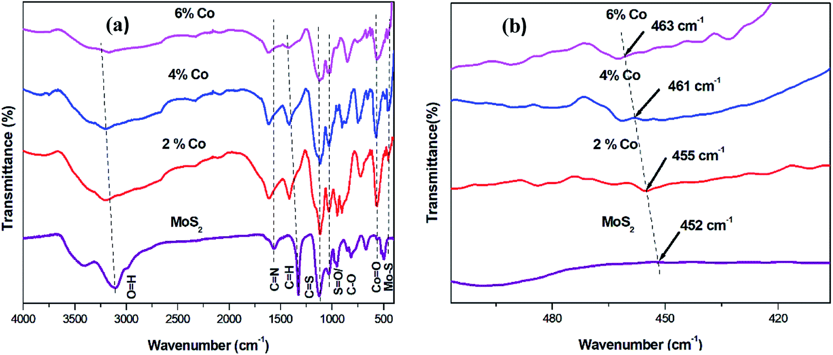
FTIR measurements were carried out in order to obtain the bending and stretching vibrations of functional groups present in the undoped and Co doped MoS2 samples. Fig. 6 depicts the FTIR spectra of all the samples under investigations. The weak peak observed at about 452 cm−1 is assigned to Mo–S vibration in undoped MoS2. The peak corresponding to 1035 cm−1 is probably due to S–O (sulfoxide) asymmetric stretching or C–O bondstretching (alcohol group). The peaks around 1200 and 1628 cm−1 in the FTIR spectra of undoped MoS2 and Co doped MoS2 confirm the existence of C–S and C–N bonds, respectively. Moreover, a broad absorption band at about 3134 cm−1 appears in the FTIR spectra is assigned to stretching vibration of the O–H bond corresponding to intercalated water. The peak around 1400 cm−1 is probably due to C–H bending mode. In addition, the new peaks arising at 561 cm−1, 567 cm−1 and 573 cm−1 for 2%, 4% and 6% Co doped MoS2, respectively corresponding to Co–O stretching mode in tetrahedral site and octahedral environment. The peak corresponding to Mo–S vibration at 452 cm−1 for undoped MoS2 shifts to 455 cm−1 for 2% Co, 461 cm−1 for 4% Co and 463 cm−1 for 6% Co doped MoS2, respectively as shown in Fig. 6(b). Here the red shift of wave number indicates Co substitution in Mo site causing decrease in effective mass of the whole system, oxygen vacancies and structural defects.56,57
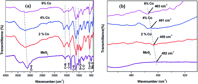 |
| | Fig. 6 (a) FTIR spectra for undoped and Co doped MoS2 (b) zoomed view of shifting of Mo–S peak. | |
3.5. Zeta potential measurement
The surface charges of undoped and Co doped MoS2 were determined from zeta potential measurement using the aqueous dispersion in neutral condition (pH-7). High value of the zeta potential (either + or −) is indicative of the stability of particles against aggregation or flocculation in the dispersion medium. All four samples showed negative surface charge, may be due to presence of carboxyl group (–COOH) which has been added during synthesis. The zeta potential values for undoped, 2%, 4%, and 6% Co doped MoS2 showed −48.3 mV, −41.2 mV, −37.5 mV and −30.8 mV, respectively.
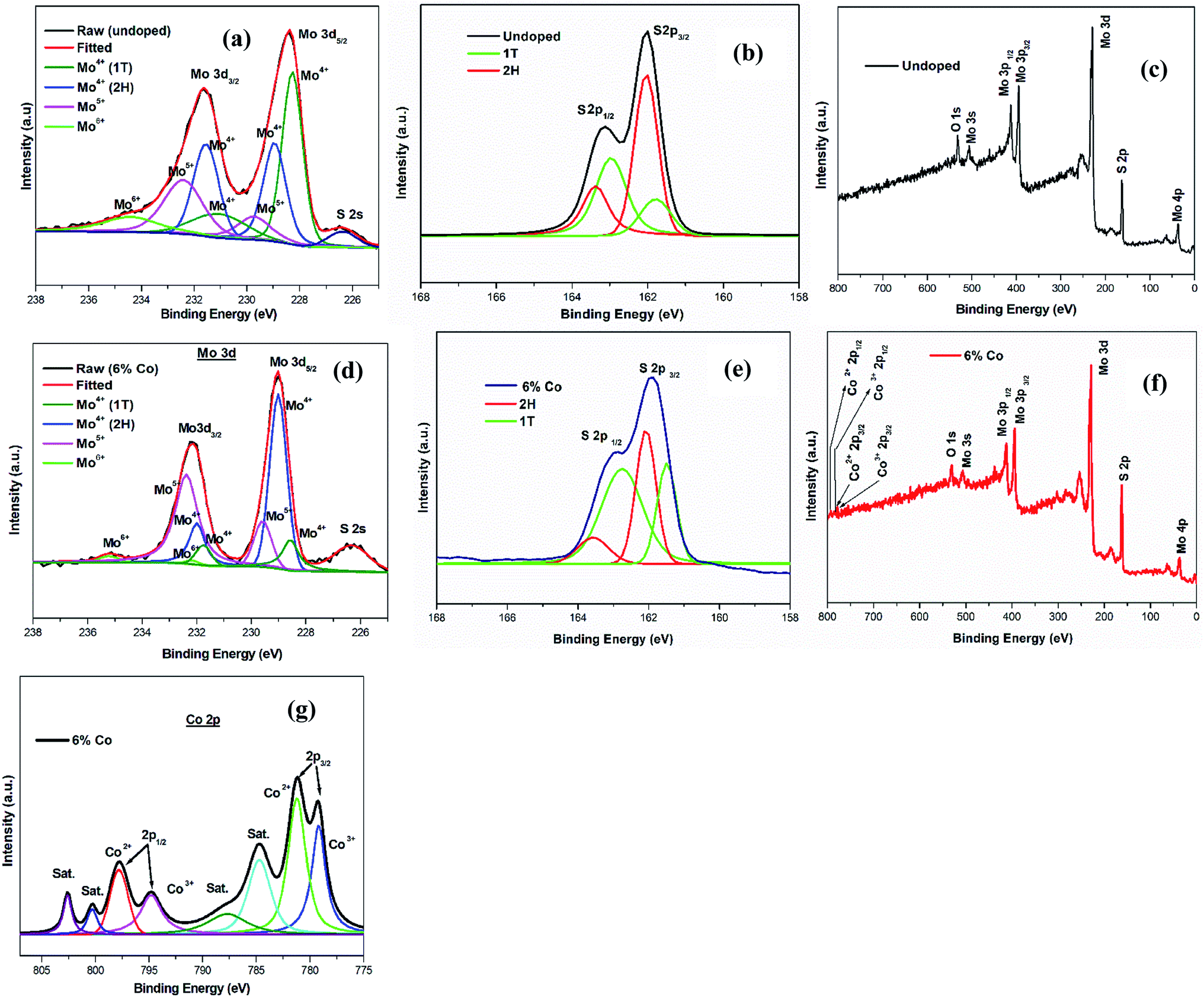
3.6. XPS study
X-ray photoelectron spectroscopic (XPS) measurements were carried out to investigate the chemical composition of undoped and 6% Co doped MoS2. As shown in the survey spectrum (wide scan) in Fig. 7(c) and (f), the elements C, Mo, S, and O can be clearly identified in undoped and C, Mo, S, O and Co in 6% Co doped MoS2 nanosheets. The typical Mo 3d5/2 and Mo 3d3/2 peaks of 2H phase appeared at 229, 231.5 eV in undoped and 229, 232 eV binding energies in 6% Co doped MoS2 along with two additional peaks shifted by about 1 eV which were assigned to Mo 3d5/2 and 3d3/2 of the 1T phase characteristic of the trigonal prismatic environment in 2H phase58 as shown in Fig. 7(a) and (d). Similarly, the S 2p3/2 and S 2p1/2 peaks of 2H phase appeared at 162.96, 163.37 eV in undoped and 162.07, 163.57 eV in 6% Co doped MoS2 binding energies, respectively as shown in Fig. 7(b) and (e). Two additional peaks shifted by about 1 eV (161.78, 162.03 eV (undoped), 161.48, 162.75 eV (6% Co doped)), from the S 2p3/2 and S 2p1/2 in 2H phase, were exhibited in both samples as expected for 1T sites. The peaks of Mo 3d5/2 and Mo 3d3/2 are shifted to higher binding energy with gradually increasing Co doping as observed in 6% Co doped MoS2. The ratios of Mo5+ to Mo4+ for undoped, 2%, 4% and 6% Co doped MoS2 are 0.28:1, 0.34:1, 0.63:1 and 0.71:1, respectively indicating the increased proportion of Mo5+ with increase of cobalt ion dopant. The separation of binding energy between Mo 3d3/2 and 3d5/2 is 3.13 eV (1T phase) and 3 eV (2H phase) in 6% Co doped MoS2, can be attributed to the dominant presence of Mo5+ ions in the cobalt doped samples59 by redox reaction of Mo4+ ↔ Mo5+ supporting the earlier result. There are four main peaks corresponding to Co 2p3/2 at 779.25 eV (Co3+), 781.25 eV (Co2+) and Co 2p1/2 at 794.75 eV (Co3+), 797.75 eV (Co2+) in 6% Co doped MoS2 as shown in Fig. 7(g). These peaks are very close to the binding energies of the Co species in CoS2.60–63 Also, another four peaks arising at 784.77, 787.75, 800.25, 802.62 eV signifies the presence of satellite shake up peaks. The binding energy of 779.25 eV is closed to what has been observed for CoMo2S4, suggesting that Co2+ substitutes Mo atoms along the {002} or the S-edge planes of MoS2 indicating the uniform doping of cobalt ions in the MoS2 substrate.48 As cobalt doping percentages is increased, so a greater number of cobalt ions are substituting the Mo lattice site. All the binding energies, peak positions corresponding to Mo, S, Co and O in case of undoped and 6% Co doped MoS2 are summarized in Table 3. The Mo 3d, S 2p and Co 2p spectrum with de-convoluted peaks of 2% and 4% Co doped MoS2 nanosheets are shown in Fig. S3(a), (d), (b), (e), (c) and (f) respectively.† The presence of higher valence state of cations Mo5+ and oxygen existing in the doped sample suggests the probability of having partially oxidized Mo2O5 species in the doped sample which could result in the generation of oxygen vacancies in the sample. The binding energy of O 1s peaks found in both the species of MoS2 centred at 530.78 eV (O (I)) belongs to the O2− ions in the hexagonal structure of undoped MoS2. The peaks centred at 530.88 eV (O (II)) belong to the oxygen vacancy defects in 6% Co and they can also serves as active sites for catalysis. In addition to redox couple present in the MoS2 matrix, a third charge compensation mechanism is possible for matrix and dopant ions through intervalence charge transfer (IVCT).
| Mo4+ + Co3+ ↔ Mo5+ + Co2+ |
 |
| | Fig. 7 XPS narrow scan spectra of Mo 3d (a) and (d) and S 2p (b) and (e), for undoped, 6% Co doped MoS2, narrow scan spectra of Co 2p (g) of 6% Co doped MoS2. Survey spectra of Mo (3d, 3p, 3s), S 2p, C 1s, Co 2p (c), (f) for undoped and 6% Co doped MoS2. | |
Table 3 Variation of oxidation peaks of Mo, S and Co in MoS2 with cobalt doping
| Doping% |
1T |
2H |
1T |
2H |
Co3+ |
Co2+ |
O 1s (eV) |
| Mo 3d5/2 (eV) |
Mo 3d3/2 (eV) |
Mo 3d5/2 (eV) |
Mo 3d3/2 (eV) |
S 2p3/2 (eV) |
S 2p1/2 (eV) |
S 2p3/2 (eV) |
S 2p1/2 (eV) |
Co 2p3/2 (eV) |
Co 2p1/2 (eV) |
Co 2p3/2 (eV) |
Co 2p1/2 (eV) |
| 0% |
228.25 |
231.12 |
229 |
231.5 |
161.78 |
162.03 |
162.96 |
163.37 |
— |
— |
— |
— |
530.78 |
| 6% |
228.62 |
231.75 |
229 |
232 |
161.48 |
162.75 |
162.07 |
163.57 |
779.25 |
794.75 |
781.25 |
797.75 |
530.88 |
The XPS data presented here subsequently confirm that the precursor valence of Mo4+ and Co3+ partially alter to Mo5+ and Co2+, which supports this mechanism.
3.7. Optical property study
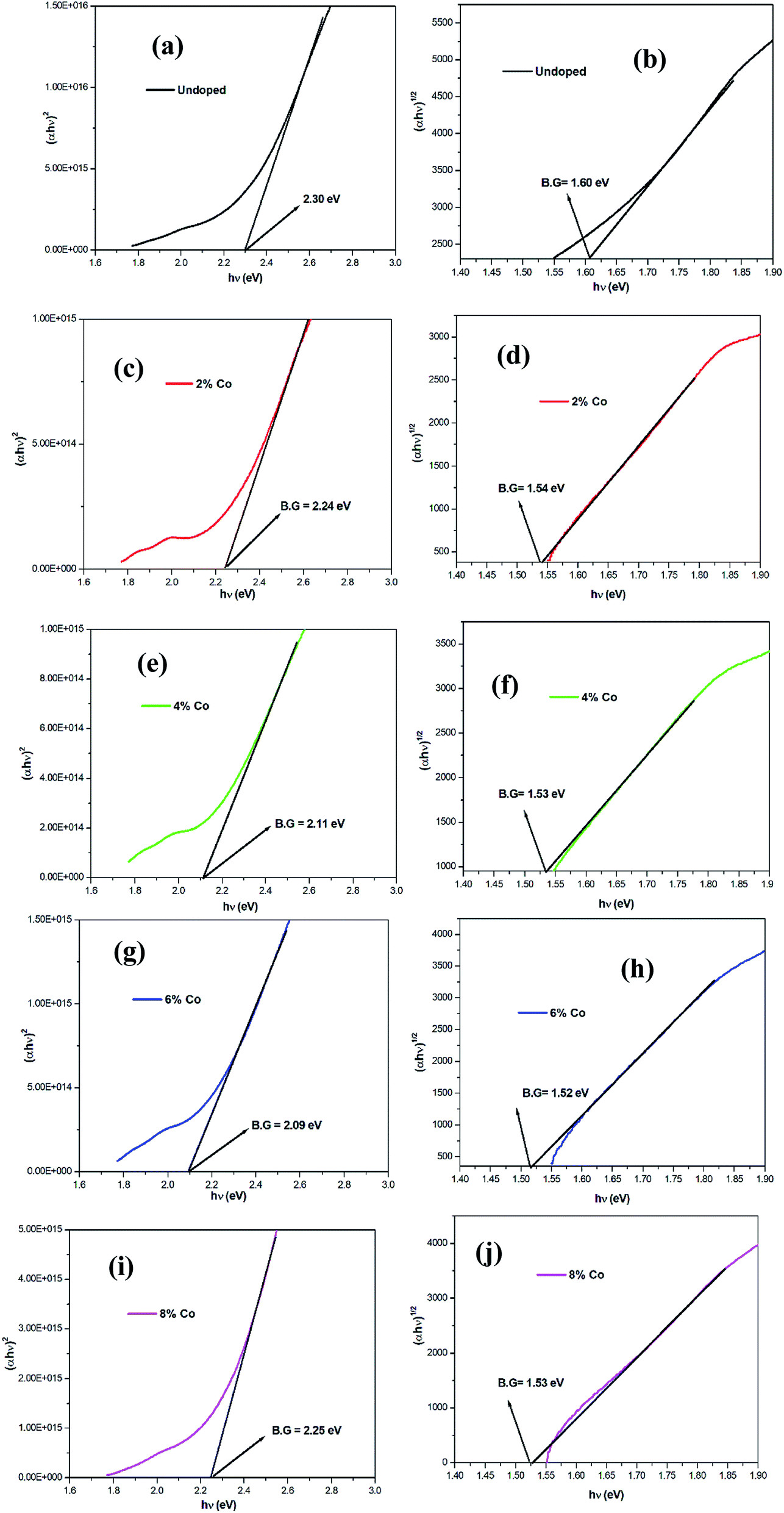
UV-vis absorption spectroscopy and Tauc's plot. Fig. 8 shows the UV-visible absorption spectra of the undoped and different percentages of cobalt doped MoS2 dispersed in DMF (dimethyl formamide). As expected, three typical characteristic absorption peaks of undoped and Co doped MoS2 are clearly observed. A prominent peak centred in the region of 430–470 nm (C exciton), and two additional peaks with relatively lower intensity are observed around ∼615 nm (B exciton) and ∼670 nm (A exciton) which correspond to excitonic transitions between the split valence band and the minima of the conduction band at the K point of Brillouin zone for MoS2 nanosheets.64 The band gaps Eg (in eV) for undoped and cobalt doped MoS2 nanostructures were calculated using the Tauc equation,
where α is the absorption coefficient (in cm−1), hν is the incident photon energy (in eV), B is a constant relative to the materials, and n = ½ (for direct allowed transition) and n = 2 (for indirect transition). Direct excitonic transition corresponding to A exciton (∼670 nm) and B exciton (∼610 nm) could be detected from UV-vis absorption spectra. Moreover, significant amount of indirect band gap contribution was observed for all the nanostructures from the Tauc plot (Fig. 10) having smaller in magnitude in comparison with direct band gap.65 The average band gap (Eg) values were estimated from the intercept of the linear portion of the (αhν)2 and (αhν)1/2 versus hν plots on the hν axis (i.e., (αhν)2 = 0 and (αhν)1/2 = 0) as shown in Fig. 10. The most interesting results, observed from individual Tauc's plot of undoped MoS2 and 2%, 4%, 6% Co2+ doped MoS2, is that the Egap, calculated from the absorption spectrum, first decreased and then increased with increasing Co2+ doping.
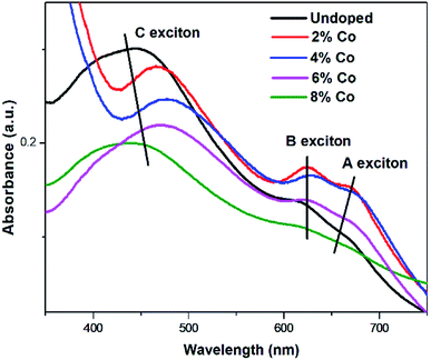 |
| | Fig. 8 UV-vis absorption spectroscopy for undoped and Co doped MoS2. | |
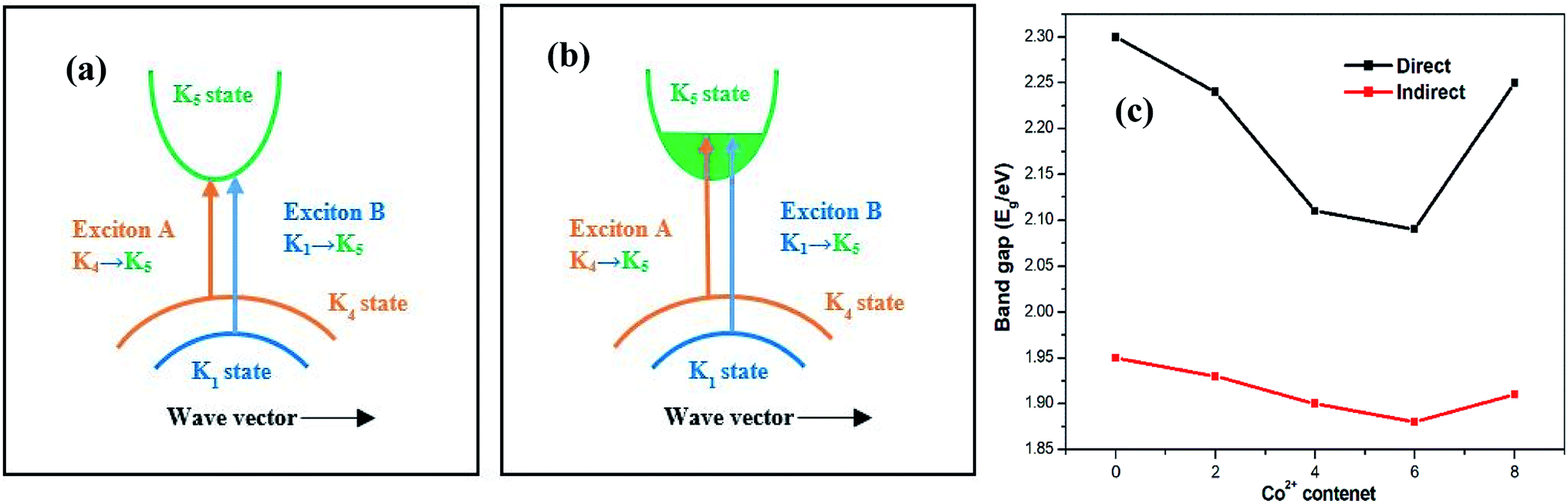
The observations indicate that the incorporation of TM ions lifts the valence band edge causing decrease in band gap which is consistent with theoretical result obtained from DFT calculation.66 In case of 8% Co doped MoS2 sample, due to incorporation of heavy amount of dopant ion, defect states appear in conduction band. Consequently, the absorption edge of the conduction band is pushed to the higher energies resulting in widening of band gap to 2.25 eV (blue shift of the excitation peaks) attributing to Moss–Burstein effect67 (Fig. 9(a)). The variation of band gap (Fig. 9(b)), exciton energies and spin–orbit splitting with various (2%, 4%, 6%, 8%) amount of cobalt doping percentages (A, B excitons) are listed in Table 4.
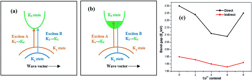 |
| | Fig. 9 Schematic view of the transitions corresponding to excitons A (K4 → K5) and B (K1 → K5) in (a) in 2H MoS2 and (b) Burstein–Moss (BM) band-filling effect in heavy cobalt ion doping. Labels are according to ref. 64. (c) Variation of direct and indirect band gap with doping concentration. | |
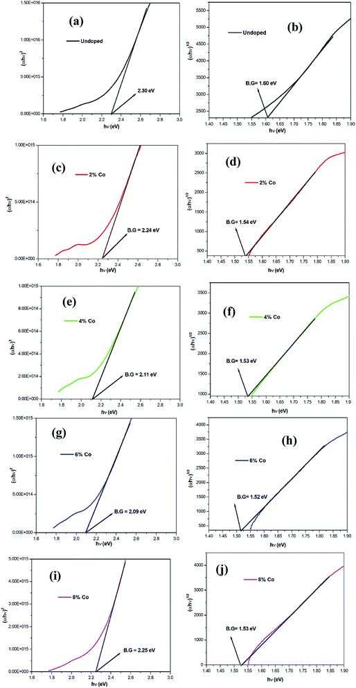 |
| | Fig. 10 Individual Tauc's plot for direct band gap (a), (c), (e), (g), (i) and indirect band gap (b), (d), (f), (h), (j) of undoped, 2%, 4%, 6% and 8% Co doped MoS2. | |
Table 4 Variation of band gap, exciton energies and spin–orbit splitting with doping (A, B excitons)
| Doping concentration |
Direct B. G (eV) |
Indirect B. G (eV) |
Exciton A (eV) |
Exciton B (eV) |
Spin–orbit splitting (eV) |
| 0% |
2.30 |
1.60 |
1.85 |
2.01 |
0.16 |
| 2% |
2.24 |
1.54 |
1.83 |
1.98 |
0.15 |
| 4% |
2.11 |
1.53 |
1.82 |
1.96 |
0.14 |
| 6% |
2.09 |
1.52 |
1.83 |
1.96 |
0.13 |
| 8% |
2.25 |
1.53 |
1.84 |
2.02 |
0.18 |
3.8. Catalytic activity
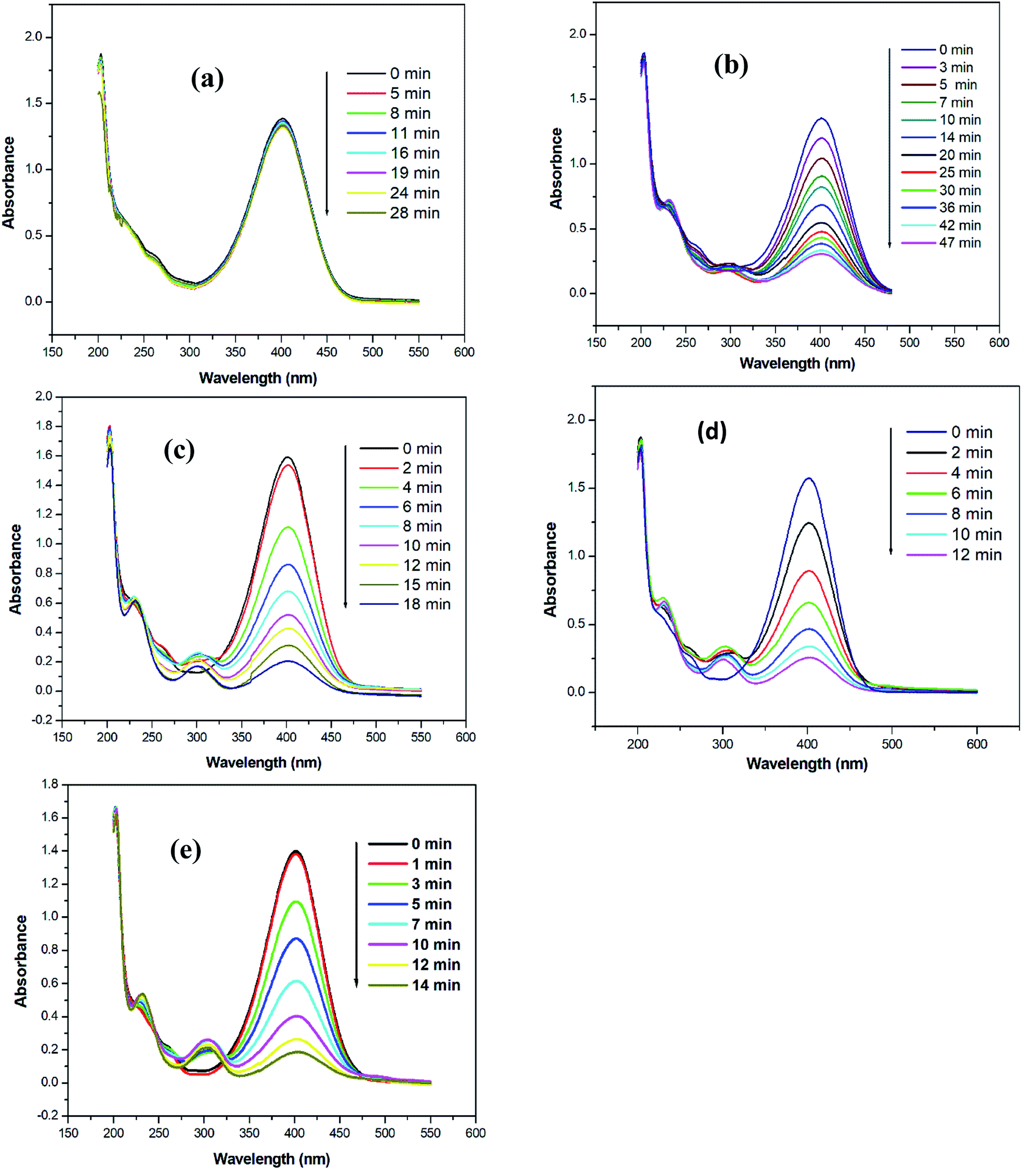
The catalytic activity of undoped and Co doped MoS2 nanostructures have been investigated through the reduction of p-nitrophenol (NP) to p-aminophenol (AP) in an excess amount of NaBH4. For the experiment, aqueous stocks of MoS2 samples, p-NP, and NaBH4 were prepared at concentrations of 2 g L−1, 10−2 (M), and 0.1 (M), respectively. The stock of NaBH4 was maintained at 4 °C to restrain the evolution of H2 gas. Aliquots of 3.0 mL of 0.1 (M) NaBH4, 20 μL of 10−2 (M) p-NP, and 5 μL of MoS2 samples were taken from the respective stocks and mixed together and their absorption spectra were monitored between 450 nm and 600 nm at different time intervals. For control, the study was also carried out in the absence of MoS2. All the graphs have been plotted based on the average values obtained from three repeat sets of the experiments.
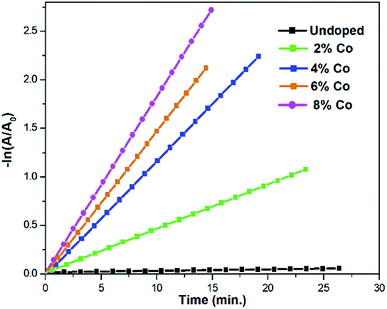
The catalytic efficiency of MoS2 and Co doped MoS2 nanostructures has been evaluated by studying the model reaction of reduction of p-NP by excess NaBH4 using UV-visible spectroscopy.44 The reduction of p-NP to p-AP by NaBH4 is not a kinetically favourable process due to large difference in the redox potential of the donor and acceptor couple (i.e., E{(H3BO3)(aq.)/(BH4−)(aq.)} = −1.33 V and E{(p-NP)(aq.)/(p-AP)(aq.)} = 0.76 V versus Normal Hydrogen Electrode (NHE), respectively.68 In the presence of a catalyst, the reaction rate is accelerated by overcoming the kinetic restrictions69 on the electron transfer from donor BH4− to acceptor p-NP. In the present reduction process, the aqueous solution of p-NP (λ = 317 nm) having light yellow colour was observed to change to deep yellow along with a spectral shift of the absorbance peak to 400 nm. The alkalinity of the solution is increased with the addition of excess of freshly prepared ice-cold aqueous solution of NaBH4 by the formation of the p-nitrophenolate ion in solution. The reduction reaction was manifested by a decrease in absorbance at λ = 400 nm with fading of the yellow colour of the solution and concurrent appearance of a gradually intensifying new peak at λ = 295 nm due to the formation of the reduced product, p-AP [Fig. 11(a)–(e)]. The reduction process of p-NP to p-AP in presence of Co doped MoS2 catalyst and NaBH4 is depicted step by step in Fig. 13. The progress of the reaction with time or the kinetics of the reaction was observed in terms of the concentrations of p-nitrophenolate ions in the reaction mixture by monitoring the changes in absorbance at λ = 400 nm at different time intervals. The reaction between p-NP and excess NaBH4 has been taken as the control, since the absorbance at λ = 400 nm was found to remain unaltered with time in the absence of undoped and Co doped MoS2 samples in the reaction mixture. It is noteworthy to mention that the presence of Co doped MoS2 nanostructures did not affect the absorbance spectra of either the p-nitrophenolate ions or p-NP because of their very low concentration69 (∼3 ppm) in the system. For the studied reduction reaction, the concentration of the reducing agent, NaBH4, has been used in large quantities (∼50 times) with respect to p-NP and catalysts. High concentration, increased pH, and ice-cold condition of the freshly prepared aqueous solution of NaBH4 ensured the stability of the borohydride anion in the reaction medium by dampening its decomposition/protonolysis to liberate hydrogen gas. Small amount of hydrogen gas was released assisted in circumventing the aerial oxidation of p-AP69 by providing a reducing atmosphere in situ. The bubbles of hydrogen gas released during the reaction also helped in stirring the reaction mixture.68 A large excess of NaBH4 compared with the concentration of p-NP also ensured that the concentration of BH4(−) ions in the reaction medium remained invariant during the reaction. In addition, occurrence of only one isosbestic point in the UV-visible absorption spectra of the reduction of p-NP (as is evident from Fig. 11) signified that the reaction mixture involved only a pair of species, p-NP and p-AP70 that varied in concentration and activity of nanocatalysts. From these observations, it may be inferred that the reduction of p-NP followed pseudo-first-order kinetics.69 Thus, by taking the absorbance of the principal species (i.e., p-nitrophenolate ions) to be proportional to their respective concentrations, the rate constant of the reaction, in the presence of undoped, 2%, 4%, 6%, 8% Co doped MoS2 was determined using the equation
| −ln(Ct/C0) = −ln(At/A0) = kt |
where
At and
A0 are the absorbance (at
λ = 400 nm) at times
t and 0, respectively, while
Ct and
C0 are the equivalent concentrations of
p-nitrophenolate ions at times
t and 0, respectively. The apparent rate constants (
k) in the presence of each of the undoped and Co doped MoS
2 nanostructured samples were determined from the slopes of the respective linear plots of [−ln(
At/
A0)]
versus time, as shown in
Fig. 12. The plots shown in
Fig. 12 depict the linearity of [−ln(
At/
A0)] with time; exponential decay profiles of the absorbance with time support pseudo-first order kinetics with respect to
p-nitrophenolate ion. From
Fig. 11(d), the 6% Co doped MoS
2 was found to be the most superior catalyst compared to the other. The turnover frequencies (TOF) of the different MoS
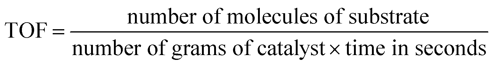
2 nanostructures with various cobalt dopant concentrations have been calculated using the expression
where 1 × 10
−2 M of
p-NP has been taken as the substrate and 2g L
−1 of the nanostructured MoS
2 as the catalyst. The variation of rate constant and turn over frequency (TOF) with cobalt doping in MoS
2 substrate are listed in
Table 5.
Table 6 presents the comparison of TOF values of different nanocomposites of MoS
2 reported earlier and our obtained results. The catalytic efficiency of MoS
2 nanostructure is enhanced with the increase of cobalt doping percentages. In Co-doped MoS
2, Co
2+ takes residence at the coordinative unsaturated sulphur vacancies on the basal plane, edge sites
23,41 substituting Mo atoms. This leads to a conversion of a fraction of Mo
4+ to Mo
3+, thus stabilizing the 1T polytype.
28 Doped Co
2+ distorts the close-packed sulphur layer of MoS
2 and induces lattice strain.
71,72 These sites would lower the reaction free energy.
41 Nitrophenol is adsorbed at the strained active sites of the MoS
2 surface.
71–73 At these sites, the electron transfer to the MoS
2 surface is facilitated by Co
2+/Co
3+ redox couple. The electrons generated by the hydrolysis of NaBH
4 are transferred to the Co
2+-accommodated basal and edge sites of 1T MoS
2 and are promoted into the MoS
2 conduction band.
71 Also, metallic Co
2+ ions may act as traps for the photo-generated electrons, due to the Schottky barrier created at the metal–semiconductor interface. As a consequence of this trapping phenomenon, the electrons generated in the photocatalytic process and trapped in the metal ions can be transferred to the adsorbed
p-NPhate ion on the surface of MoS
2. The electron transfer from the semiconductor to the nitro group of the
p-nitrophenolate ion favours the reaction to the formation of the
p-AP product. Co substituted sites not only raise faster electron transfer for nitrophenol reduction through reversible reduction–oxidation reactions but also serve as an electron reserve and aid in the retention of the 1T phase with enhanced electrical conductivity. In our study the optimal dopant concentration obtained is 6 at. wt%. since higher concentration (8 at. wt%) of cobalt ion loading possibly leads to partial blockage of catalytic active sites of MoS
2 support surface resulting in enhanced frequency of charge carrier recombination.
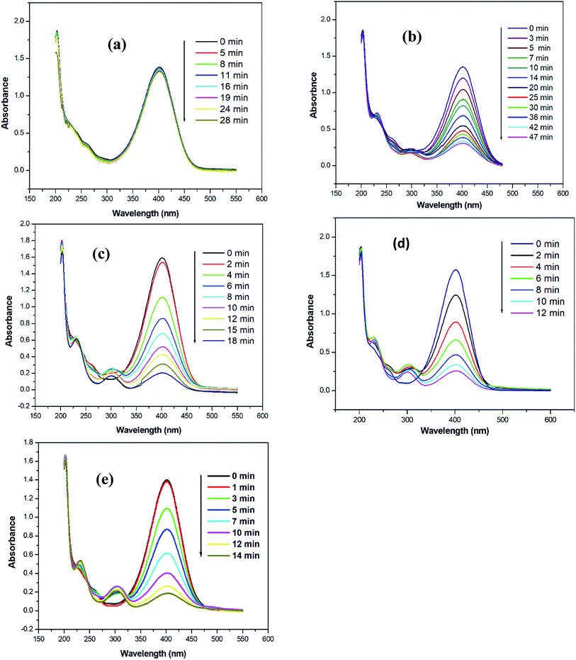 |
| | Fig. 11 Time-dependent UV-visible absorption spectra of the reduction of p-NP by excess NaBH4 in the presence of: (a) undoped MoS2; (b) 2% Co doped MoS2; (c) 4% Co doped MoS2; (d) 6% Co doped MoS2; and (e) 8% Co doped MoS2. Condition: [p-NP] = 10−2 M, [NaBH4] = 0.1 M, and [Catalyst] = 2 g L−1. | |
 |
| | Fig. 12 Plots of −ln(At/A0) versus time for the reduction of p-NP by NaBH4 in the presence of undoped MoS2, 2% Co, 4% Co, 6% and 8% Co doped MoS2 nanostructures. Conditions: 3.0 mL of 0.1 M NaBH4, 20 μL of 10−2 M 4-NP, and 5 μL of 2 g L−1 nanocatalysts. | |
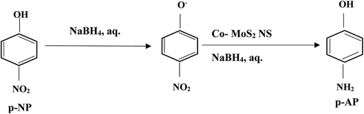 |
| | Fig. 13 Diagram of the reduction of p-nitrophenol (p-NP) to p-aminophenol (p-AP) by NaBH4 catalysed by cobalt doped MoS2 NP. | |
Table 5 Enhancement of rate constant and TOF with increasing cobalt doping in MoS2
| Doping percentages |
Rate constant (k; s−1) |
TOF (molecules per g per s) |
| 0% |
2.55 × 10⁻⁵ |
1.02 × 10¹⁷ |
| 2% |
5.16 × 10⁻⁴ |
1.06 × 10¹⁸ |
| 4% |
1.95 × 10⁻³ |
2.70 × 10¹⁸ |
| 6% |
3.03 × 10⁻³ |
4.18 × 10¹⁸ |
| 8% |
2.45 × 10⁻³ |
3.13 × 10¹⁸ |
Table 6 Comparison of the TOF values for the catalytic reduction of p-NP
| Catalyst sample |
TOF (min−1) |
Reference |
| 2H-chemically exfoliated MoS2 |
1.5 × 10⁻² |
(Guardia et al. 2014)74 |
| MoS2–rGO |
1.50 × 10⁻¹ |
(Anto Jeffery et al. 2017)75 |
| MoS2–Pd |
3.20 × 10⁻³ |
(Qiao et al. 2017)76 |
| MoS2–Fe3O4 |
4.00 × 10⁻² |
(Lin et al. 2015)77 |
| MoS2–Fe3O4/Pt |
6.00 × 10⁻⁴ |
(Cheng et al. 2015)78 |
| MoS2 |
5.11 × 10⁻³ |
(Qiao et al. 2018)79 |
| MoS2 |
2.50 × 10⁻³ |
This work |
| 2% Co doped MoS2 |
3.10 × 10⁻² |
This work |
| 4% Co doped MoS2 |
1.17 × 10⁻¹ |
This work |
| 6%Co doped MoS2 |
1.82 × 10⁻¹ |
This work |
| 8% Co doped MoS2 |
1.47 × 10⁻¹ |
This work |
| Ni–Co alloy |
4.63 × 10⁻³ |
(Wu et al. 2011)80 |
| Au–Fe3O4 NPs |
2.80 × 10⁻³ |
(Lin et al. 2011)81 |
| Pd–Fe3O4@SiO2 |
1.95 × 10⁻² |
(Wang et al. 2014)82 |
| AgNPs |
2.09 × 10⁻³ |
(Liang et al. 2013)83 |
4. Conclusion
Undoped and various (2%, 4%, 6% and 8%) atomic weight percentages of cobalt doped MoS2 nanosheets with the cobalt ion activated on defective basal planes, S-edges, Mo sites are synthesized in a single-step hydrothermal reaction process. The effectiveness of the prepared MoS2 nanostructures as catalysts for the reduction of 4-nitrophenol to 4-aminophenol in excess NaBH4 has been assessed. All prepared morphologies of MoS2 nanostructures were found to be effective and stable catalysts and followed pseudo-first-order kinetics. The catalytic activity property was clearly observed to enhance with cobalt doping percentages and also provides far more improved result compared to noble metal and rGO-based MoS2 nanocomposites reported earlier. Readily dispersible in polar solvents like water or methanol, the 6% Co-doped MoS2 nanosheets exhibit exceptional catalytic activity toward reduction of harmful nitrophenol from waste waters at ambient temperature exhibiting high turnover frequency (4.18 × 10¹⁸ molecules per g per s). Apart from that the observed high negative zeta potential indicates that our reported samples are stable against aggregation in dispersion medium. The superior catalytic activity of the highest 6% Co doped MoS2 layers is possibly due to a combination of (a) stabilization of the metallic 1T phase with increasing electrical conductivity (decreasing band gap and activation energy) and (b) better electron capture from the hydride and electron supply to the nitrophenol substrates through reversible redox reactions at the Co sites. In a nutshell, our study clearly exhibits that proper tuning of Co doping in MoS2 nanosheets is another potential alternative of noble metal catalyst for the catalytic reduction of nitroarene.
Conflicts of interest
There are no conflicts to declare.
Acknowledgements
The authors acknowledge the XPS facility, Department of Physics, IIT Kharagpur and Central Research Facility (CRF), IIT Kharagpur for providing the infrastructural support for the characterization of the samples. R. Rahman is grateful for the DST-INSPIRE fellowship provided by DST, India for supporting financially to carry out the present research work.
References
- M. Chhowalla, H. S. Shin, G. Eda, L. Li, K. P. Loh and H. Zhang, The chemistry of two-dimensional layered transition metal dichalcogenide nanosheets, Nat. Chem., 2013, 5, 263–275 CrossRef.
- B. Hinnemann, P. G. Moses, J. Bonde, K. P. Jørgensen, J. H. Nielsen, S. Horch, I. Chorkendorff and J. K. Nørskov, Biomimetic hydrogen evolution: MoS2 nanoparticles as catalyst for hydrogen evolution, J. Am. Chem. Soc., 2005, 127, 5308–5309 CrossRef CAS.
- X. Chia, A. Y. S. Eng, A. Ambrosi, S. M. Tan and M. Pumera, Electrochemistry of Nanostructured Layered Transition-Metal Dichalcogenides, Chem. Rev., 2015, 115, 11941–11966 CrossRef CAS.
- T. F. Jaramillo, K. P. Jorgensen, J. Bonde, J. H. Nielsen, S. Horch and I. Chorkendorff, Identification of Active Edge Sites for Electrochemical H2 Evolution from MoS2 Nanocatalysts, Science, 2007, 317, 100–102 CrossRef CAS.
- G. A. Somorjai and V. H. J. De Beer, Structure and Function of The Catalyst and The Promoter In Co—Mo Hydrodesuifurization Catalysts, Catal. Rev., 1989, 31, 1–41 CrossRef.
- P. Clark, W. Li and S. T. Oyama, Synthesis and activity of a new catalyst for hydroprocessing: Tungsten phosphide, J. Catal., 2001, 200, 140–147 CrossRef CAS.
- C. Ataca, H. Şahin, E. Aktuörk and S. Ciraci, Mechanical and electronic properties of MoS2 nanoribbons and their defects, J. Phys. Chem. C, 2011, 115, 3934–3941 CrossRef CAS.
- J. Heising and M. G. Kanatzidis, Structure of restacked MoS2 and WS2 elucidated by electron crystallography, J. Am. Chem. Soc., 1999, 121, 638–643 CrossRef CAS.
- F. Wypych and R. Schöllhorn, 1T-MoS2, a new metallic modification of molybdenum disulfide, J. Chem. Soc., Chem. Commun., 1992, 1386–1388 RSC.
- B. Radisavljevic, A. Radenovic, J. Brivio, V. Giacometti and A. Kis, Single-layer MoS2 transistors, Nat. Nanotechnol., 2011, 6, 147–150 CrossRef CAS.
- K. Zhang, S. Feng, J. Wang, A. Azcatl, N. Lu, R. Addou, N. Wang, C. Zhou, J. Lerach, V. Bojan, M. J. Kim, L. Q. Chen, R. M. Wallace, M. Terrones, J. Zhu and J. A. Robinson, Manganese Doping of Monolayer MoS 2: The Substrate Is Critical, Nano Lett., 2015, 15, 6586–6591 CrossRef CAS.
- J. Shakya, S. Kumar, D. Kanjilal and T. Mohanty, Work Function Modulation of Molybdenum Disulfide Nanosheets by Introducing Systematic Lattice Strain, Sci. Rep., 2017, 7, 9576 CrossRef.
- J. Li, C. Y. Liu and Y. Liu, Au/graphene hydrogel: Synthesis, characterization and its use for catalytic reduction of 4-nitrophenol, J. Mater. Chem., 2012, 22, 8426–8430 RSC.
- Y. Li, Y. Cao, J. Xie, D. Jia, H. Qin and Z. Liang, Facile solid-state synthesis of Ag/graphene oxide nanocomposites as highly active and stable catalyst for the reduction of 4-nitrophenol, Catal. Commun., 2015, 58, 21–25 CrossRef CAS.
- J. J. Lv, A. J. Wang, X. Ma, R. Y. Xiang, J. R. Chen and J. J. Feng, One-pot synthesis of porous Pt-Au nanodendrites supported on reduced graphene oxide nanosheets toward catalytic reduction of 4-nitrophenol, J. Mater. Chem. A, 2015, 3, 290–296 RSC.
- X. Chen, X. Chen, Z. Cai and M. Oyama, AuPd bimetallic nanoparticles decorated on graphene nanosheets: Their green synthesis, growth mechanism and high catalytic ability in 4-nitrophenol reduction, J. Mater. Chem. A, 2014, 2, 5668–5674 RSC.
- K. Layek, M. L. Kantam, M. Shirai, D. Nishio-Hamane, T. Sasaki and H. Maheswaran, Gold nanoparticles stabilized on nanocrystalline magnesium oxide as an active catalyst for reduction of nitroarenes in aqueous medium at room temperature, Green Chem., 2012, 14, 3164–3174 RSC.
- J. Lee, J. C. Park and H. Song, A Nanoreactor framework of a Au@SiO2 yolk/shell structure for catalytic reduction of p-nitrophenol, Adv. Mater., 2008, 20, 1523–1528 CrossRef CAS.
- Y. Li, Q. Chen, Z. Zhang, Q. Li and X. Qiao, Effects of morphology and crystallinity of MoS2 nanocrystals on the catalytic reduction of p-nitrophenol, J. Nanoparticle Res., 2018, 20, 327 CrossRef.
- J. D. Benck, Z. Chen, L. Y. Kuritzky, A. J. Forman and T. F. Jaramillo, Amorphous molybdenum sulfide catalysts for electrochemical hydrogen production: Insights into the origin of their catalytic activity, ACS Catal., 2012, 2, 1916–1923 CrossRef CAS.
- D. Merki and X. Hu, Recent developments of molybdenum and tungsten sulfides as hydrogen evolution catalysts, Energy Environ. Sci., 2011, 4, 3878 RSC.
- C. G. Morales-Guio and X. Hu, Amorphous molybdenum sulfides as hydrogen evolution catalysts, Acc. Chem. Res., 2014, 47, 2671–2681 CrossRef CAS.
- J. Bonde, P. G. Moses, T. F. Jaramillo, J. K. Nørskov and I. Chorkendorff, Hydrogen evolution on nano-particulate transition metal sulfides, Faraday Discuss., 2008, 140, 219–231 RSC.
- J. Kibsgaard, Z. Chen, B. N. Reinecke and T. F. Jaramillo, Engineering the surface structure of MoS2 to  preferentially expose active edge sites for electrocatalysis, Nat. Mater., 2012, 11, 963–969 CrossRef CAS.
- J. Xie, H. Zhang, S. Li, R. Wang, X. Sun, M. Zhou, J. Zhou, X. W. Lou and Y. Xie, Defect-rich MoS2 ultrathin nanosheets with additional active edge sites for enhanced electrocatalytic hydrogen evolution, Adv. Mater., 2013, 25, 5807–5813 CrossRef CAS.
- J. Xie, J. Zhang, S. Li, F. Grote, X. Zhang, H. Zhang, R. Wang, Y. Lei, B. Pan and Y. Xie, Controllable disorder engineering in oxygen-incorporated MoS2 ultrathin nanosheets for efficient hydrogen evolution, J. Am. Chem. Soc., 2013, 135, 17881–17888 CrossRef CAS.
- D. Kong, H. Wang, J. J. Cha, M. Pasta, K. J. Koski, J. Yao and Y. Cui, Synthesis of MoS2 and MoSe2 films with vertically aligned layers, Nano Lett., 2013, 13, 1341–1347 CrossRef CAS.
- H. Wang, Z. Lu, S. Xu, D. Kong, J. J. Cha, G. Zheng, P. C. Hsu, K. Yan, D. Bradshaw, F. B. Prinz and Y. Cui, Electrochemical tuning of vertically aligned MoS2 nanofilms and its application in improving hydrogen evolution reaction, Proc. Natl. Acad. Sci. U. S. A., 2013, 110, 19701–19706 CrossRef CAS.
- Y. Li, H. Wang, L. Xie, Y. Liang, G. Hong and H. Dai, MoS2 nanoparticles grown on graphene: An advanced catalyst for the hydrogen evolution reaction, J. Am. Chem. Soc., 2011, 133, 7296–7299 CrossRef CAS.
- H. Wang, Z. Lu, D. Kong, J. Sun, T. M. Hymel and Y. Cui, Electrochemical tuning of MoS2 nanoparticles on three-dimensional substrate for efficient hydrogen evolution, ACS Nano, 2014, 8, 4940–4947 CrossRef CAS.
- A. A. Jeffery, S. R. Rao and M. Rajamathi, Preparation of MoS2–reduced graphene oxide (rGO) hybrid paper for catalytic applications by simple exfoliation–costacking, Carbon, 2017, 112, 8–16 CrossRef CAS.
- F. Z. Wang, M. J. Zheng, B. Zhang, C. Q. Zhu, Q. Li, L. Ma and W. Z. Shen, Ammonia intercalated flower-like MoS2 nanosheet film as electrocatalyst for high efficient and stable hydrogen evolution, Sci. Rep., 2016, 6, 31092 CrossRef CAS.
- M.-R. Gao, J.-X. Liang, Y.-R. Zheng, Y.-F. Xu, J. Jiang, Q. Gao, J. Li and S.-H. Yu, An efficient molybdenum disulfide/cobalt diselenide hybrid catalyst for electrochemical hydrogen generation, Nat. Commun., 2015, 6, 5982 CrossRef CAS.
- J. Huang, D. Hou, Y. Zhou, W. Zhou, G. Li, Z. Tang, L. Li and S. Chen, MoS2 nanosheet-coated CoS2 nanowire arrays on carbon cloth as three-dimensional electrodes for efficient electrocatalytic hydrogen evolution, J. Mater. Chem. A, 2015, 3, 22886–22891 RSC.
- R. Bose, Z. Jin, S. Shin, S. Kim, S. Lee and Y. S. Min, Co-catalytic Effects of CoS2 on the Activity of the MoS2 Catalyst for Electrochemical Hydrogen Evolution, Langmuir, 2017, 33, 5628–5635 CrossRef CAS.
- W. Wang, L. Li, K. Wu, G. Zhu, S. Tan, Y. Liu and Y. Yang, Highly selective catalytic conversion of phenols to aromatic hydrocarbons on CoS2/MoS2 synthesized using a two step hydrothermal method, RSC Adv., 2016, 6, 31265–31271 RSC.
- I. Sorribes, L. Liu and A. Corma, Nanolayered Co-Mo-S Catalysts for the Chemoselective Hydrogenation of Nitroarenes, ACS Catal., 2017, 7, 2698–2708 CrossRef CAS.
- X. L. Yin, L. L. Li, W. J. Jiang, Y. Zhang, X. Zhang, L. J. Wan and J. S. Hu, MoS2/CdS Nanosheets-on-Nanorod Heterostructure for Highly Efficient Photocatalytic H2 Generation under Visible Light Irradiation, ACS Appl. Mater. Interfaces, 2016, 8, 15258–15266 CrossRef CAS.
- Y. Liu, Y. X. Yu and W. De Zhang, MoS2/CdS heterojunction with high photoelectrochemical activity for H2 evolution under visible light: The role of MoS2, J. Phys. Chem. C, 2013, 117, 12949–12957 CrossRef CAS.
- T. Lin, J. Wang, L. Guo and F. Fu, Fe3O4@MoS2 core-shell composites: Preparation, characterization, and catalytic application, J. Phys. Chem. C, 2015, 119, 13658–13664 CrossRef CAS.
- D. Voiry, H. Yamaguchi, J. Li, R. Silva, D. C. B. Alves, T. Fujita, M. Chen, T. Asefa, V. B. Shenoy, G. Eda and M. Chhowalla, Enhanced catalytic activity in strained chemically exfoliated WS 2 nanosheets for hydrogen evolution, Nat. Mater., 2013, 12, 850–855 CrossRef CAS.
- M. A. Lukowski, A. S. Daniel, F. Meng, A. Forticaux, L. Li and S. Jin, Enhanced hydrogen evolution catalysis from chemically exfoliated metallic MoS2 nanosheets, J. Am. Chem. Soc., 2013, 135, 10274–10277 CrossRef CAS.
- Y. Wang, B. J. Carey, W. Zhang, A. F. Chrimes, L. Chen, K. Kalantar-Zadeh, J. Z. Ou and T. Daeneke, Intercalated 2D MoS2 Utilizing a Simulated Sun Assisted Process: Reducing the HER Overpotential, J. Phys. Chem. C, 2016, 120, 2447–2455 CrossRef CAS.
- X. Q. Qiao, Z. W. Zhang, F. Y. Tian, D. F. Hou, Z. F. Tian, D. S. Li and Q. Zhang, Enhanced Catalytic Reduction of p-Nitrophenol on Ultrathin MoS2 Nanosheets Decorated with Noble Metal Nanoparticles, Cryst. Growth Des., 2017, 17, 3538–3547 CrossRef CAS.
- Y. Yan, B. Xia, Z. Xu and X. Wang, Recent Development of Molybdenum Sulfides as Advanced Electrocatalysts for Hydrogen Evolution Reaction, ACS Catal., 2014, 4, 1693–1705 CrossRef CAS.
- D. Merki, H. Vrubel, L. Rovelli, S. Fierro and X. Hu, Fe, Co, and Ni ions promote the catalytic activity of amorphous molybdenum sulfide films for hydrogen evolution, Chem. Sci., 2012, 3, 2515–2525 RSC.
- H. Wang, H. Yuan, S. Sae Hong, Y. Li and Y. Cui, Physical and chemical tuning of two-dimensional transition metal dichalcogenides, Chem. Soc. Rev., 2015, 44, 2664–2680 RSC.
- C. Nethravathi, J. Prabhu, S. Lakshmipriya and M. Rajamathi, Magnetic Co-Doped MoS 2 Nanosheets for Efficient Catalysis of Nitroarene Reduction, ACS Omega, 2017, 2, 5891–5897 CrossRef CAS.
- G. Liu, A. W. Robertson, M. M. J. Li, W. C. H. Kuo, M. T. Darby, M. H. Muhieddine, Y. C. Lin, K. Suenaga, M. Stamatakis, J. H. Warner and S. C. E. Tsang, MoS2 monolayer catalyst doped with isolated Co atoms for the hydrodeoxygenation reaction, Nat. Chem., 2017, 9, 810–816 CrossRef CAS.
- A. Azcatl, X. Qin, A. Prakash, C. Zhang, L. Cheng, Q. Wang, N. Lu, M. J. Kim, J. Kim, K. Cho, R. Addou, C. L. Hinkle, J. Appenzeller and R. M. Wallace, Covalent Nitrogen Doping and Compressive Strain in MoS2 by Remote N2 Plasma Exposure, Nano Lett., 2016, 16, 5437–5443 CrossRef CAS.
- J. Wang, F. Sun, S. Yang, Y. Li, C. Zhao, M. Xu, Y. Zhang and H. Zeng, Robust ferromagnetism in Mn-doped MoS 2 nanostructures, Appl. Phys. Lett., 2016, 109, 092401 CrossRef.
- S. Pak, J. Lee, Y. W. Lee, A. R. Jang, S. Ahn, K. Y. Ma, Y. Cho, J. Hong, S. Lee, H. Y. Jeong, H. Im, H. S. Shin, S. M. Morris, S. Cha, J. I. Sohn and J. M. Kim, Strain-Mediated Interlayer Coupling Effects on the Excitonic Behaviors in an Epitaxially Grown MoS2/WS2 van der Waals Heterobilayer, Nano Lett., 2017, 17, 5634–5640 CrossRef CAS.
- X. Dai, K. Du, Z. Li, M. Liu, Y. Ma, H. Sun, X. Zhang and Y. Yang, Co-Doped MoS2 Nanosheets with the Dominant CoMoS Phase Coated on Carbon as an Excellent Electrocatalyst for Hydrogen Evolution, ACS Appl. Mater. Interfaces, 2015, 7, 27242–27253 CrossRef CAS.
- H. Li, Q. Zhang, C. C. R. Yap, B. K. Tay, T. H. T. Edwin, A. Olivier and D. Baillargeat, From bulk to monolayer MoS 2: Evolution of Raman scattering, Adv. Funct. Mater., 2012, 22, 1385–1390 CrossRef CAS.
- M. R. Gao, M. K. Y. Chan and Y. Sun, Edge-terminated molybdenum disulfide with a 9.4-Å interlayer spacing for electrochemical hydrogen production, Nat. Commun., 2015, 6, 1–8 Search PubMed.
- A. El Mragui, Y. Logvina, L. Pinto da Silva, O. Zegaoui and J. C. G. Esteves da Silva, Synthesis of Fe- and Co-Doped TiO2 with Improved Photocatalytic Activity Under Visible Irradiation Toward Carbamazepine Degradation, Materials, 2019, 12, 3874 CrossRef CAS.
- K. Das, S. N. Sharma, M. Kumar and S. K. De, Morphology dependent luminescence properties of Co doped TiO2 nanostructures, J. Phys. Chem. C, 2009, 113, 14783–14792 CrossRef CAS.
- N. Thi Xuyen and J.-M. Ting, Hybridized 1T/2H MoS 2 Having Controlled 1T Concentrations and its use in Supercapacitors, Chem. - Eur. J., 2017, 23, 17348–17355 CrossRef CAS.
- S. Eijsbouts, J. J. L. Heinerman and H. J. W. Elzerman, MoS2 structures in high-activity hydrotreating catalysts. I. Semi-quantitative method for evaluation of transmission electron microscopy results. Correlations between hydrodesulfurization and hydrodenitrogenation activities and MoS2 dispersion, Appl. Catal., A, 1993, 105, 53–68 CrossRef CAS.
- M. S. Faber, R. Dziedzic, M. A. Lukowski, N. S. Kaiser, Q. Ding and S. Jin, High-performance electrocatalysis using metallic cobalt pyrite (CoS 2) micro- and nanostructures, J. Am. Chem. Soc., 2014, 136, 10053–10061 CrossRef CAS.
- M. Cabán-Acevedo, M. L. Stone, J. R. Schmidt, J. G. Thomas, Q. Ding, H. C. Chang, M. L. Tsai, H. He and S. Jin, Efficient hydrogen evolution catalysis using ternary pyrite-type cobalt phosphosulphide, Nat. Mater., 2015, 14, 1245–1251 CrossRef.
- D. C. Higgins, F. M. Hassan, M. H. Seo, J. Y. Choi, M. A. Hoque, D. U. Lee and Z. Chen, Shape-controlled octahedral cobalt disulfide nanoparticles supported on nitrogen and sulfur-doped graphene/carbon nanotube composites for oxygen reduction in acidic electrolyte, J. Mater. Chem. A, 2015, 3, 6340–6350 RSC.
- G. Zhang, W. Lu, F. Cao, Z. Xiao and X. Zheng, N-doped graphene coupled with Co nanoparticles as an efficient electrocatalyst for oxygen reduction in alkaline media, J. Power Sources, 2016, 302, 114–125 CrossRef CAS.
- N. Dong, Y. Li, Y. Feng, S. Zhang, X. Zhang, C. Chang, J. Fan, L. Zhang and J. Wang, Optical Limiting and Theoretical Modelling of Layered Transition Metal Dichalcogenide Nanosheets, Sci. Rep., 2015, 5, 14646 CrossRef CAS.
- N. Saha, A. Sarkar, A. B. Ghosh, A. K. Dutta, G. R. Bhadu, P. Paul and B. Adhikary, Highly active spherical amorphous MoS2: Facile synthesis and application in photocatalytic degradation of rose bengal dye and hydrogenation of nitroarenes, RSC Adv., 2015, 5, 88848–88856 RSC.
- A. Ramasubramaniam and D. Naveh, Mn-doped monolayer MoS2: An atomically thin dilute magnetic semiconductor, Phys. Rev. B: Condens. Matter Mater. Phys., 2013, 87, 1–7 CrossRef.
- Q. C. Sun, L. Yadgarov, R. Rosentsveig, G. Seifert, R. Tenne and J. L. Musfeldt, Observation of a Burstein–Moss Shift in Rhenium-Doped MoS 2 Nanoparticles, ACS Nano, 2013, 7, 3506–3511 CrossRef CAS.
- S. Saha, A. Pal, S. Kundu, S. Basu and T. Pal, Photochemical green synthesis of calcium-alginate-stabilized ag and au nanoparticles and their catalytic application to 4-nitrophenol reduction, Langmuir, 2010, 26, 2885–2893 CrossRef CAS.
- A. Gangula, R. Podila, R. M. L. Karanam, C. Janardhana and A. M. Rao, Catalytic reduction of 4-nitrophenol using biogenic gold and silver nanoparticles derived from breynia rhamnoides, Langmuir, 2011, 27, 15268–15274 CrossRef.
- G. Q. Gao, L. Lin, C. M. Fan, Q. Zhu, R. X. Wang and A. W. Xu, Highly dispersed platinum nanoparticles generated in viologen micelles with high catalytic activity and stability, J. Mater. Chem. A, 2013, 1, 12206–12212 RSC.
- J. Brenner, C. L. Marshall, L. Ellis, N. Tomczyk, J. Heising and M. Kanatzidis, Microstructural Characterization of Highly HDS-Active Co6S8-Pillared Molybdenum Sulfides, Chem. Mater., 1998, 10, 1244–1257 CrossRef CAS.
- R. R. Chianelli, A. F. Ruppert, M. José-Yacamán and A. Vázquez-Zavala, HREM studies of layered transition metal sulfide catalytic materials, Catal. Today, 1995, 23, 269–281 CrossRef CAS.
- H. Li, S. Chen, X. Jia, B. Xu, H. Lin, H. Yang, L. Song and X. Wang, Amorphous nickel-cobalt complexes hybridized with 1T-phase molybdenum disulfide via hydrazine-induced phase transformation for water splitting, Nat. Commun., 2017, 8, 15377 CrossRef CAS.
- L. Guardia, J. I. Paredes, J. M. Munuera, S. Villar-Rodil, M. Ayan-Varela, A. Martinez-Alonso and J. M. D. Tascon, Chemically Exfoliated MoS2 Nanosheets as an Efficient Catalyst for Reduction Reactions in the Aqueous Phase, ACS Appl. Mater. Interfaces, 2014, 6, 21702–21710 CrossRef CAS.
- A. A. Jeffery, S. R. Rao and M. Rajamathi, Preparation of MoS2–reduced graphene oxide (rGO) hybrid paper for catalytic applications by simple exfoliation–costacking, Carbon, 2017, 112, 8–16 CrossRef CAS.
- X. Q. Qiao, Z. W Zhang, F. Y. Tian, D. F Hou, Z. F. Tian, D. S Li and Q. Zhang, Enhanced Catalytic Reduction of p-Nitrophenol on Ultrathin MoS2 Nanosheets Decorated with Noble Metal Nanoparticles, Cryst. Growth Des., 2017, 17, 3538–3547 CrossRef CAS.
- T. Lin, J. Wang, L. Guo and F. Fu, Fe3O4@MoS2 Core–Shell Composites: Preparation, Characterization, and Catalytic Application, J. Phys. Chem. C, 2015, 119, 13658–13664 CrossRef CAS.
- Z. Cheng, B. He and L. Zhou, A general one-step approach for in situ decoration of MoS2 nanosheets with inorganic nanoparticles, J. Mater. Chem. A, 2015, 3, 1042–1048 RSC.
- X. Q. Qiao, Z. W. Zhang, D. F. Hou, D. S. Li, Y. Liu, Y. Q. Lan, J. Zhang, P. Feng and X. Bu, Tunable MoS2/SnO2 P–N Heterojunctions for an Efficient Trimethylamine Gas Sensor and 4-Nitrophenol Reduction Catalyst, ACS Sustainable Chem. Eng., 2018, 6, 12375–12384 CrossRef CAS.
- C. Wu, Y. Bai, D. X. Liu, F. Wu, M. L. Pang and B. L. Yi, Ni–Co–B catalyst-promoted hydrogen generation by hydrolyzing NaBH4 solution for in situ hydrogen supply of portable fuel cells, Catalysis Today, 2011, 170, 33–39 CrossRef CAS.
- F. Lin and R. Doong, Bifunctional Au−Fe3O4 Heterostructures for Magnetically Recyclable Catalysis of Nitrophenol Reduction, J. Phys. Chem. C, 2011, 115, 6591–6598 CrossRef CAS.
- P. Wang, H. Liu, J. Niu, R. Li and J. Ma, Entangled Pd complexes over Fe3O4@SiO2 as supported catalysts for hydrogenation and Suzuki reactions, Catal. Sci. Technol., 2014, 4, 1333–1339 RSC.
- M. Liang, L. Wang, R. Su, W. Qi, M. Wang, Y. Yu and Z. He, Synthesis of silver nanoparticles within cross-linked lysozyme crystals as recyclable catalysts for 4-nitrophenol reduction, Catal. Sci. Technol., 2013, 3, 1910–1914 RSC.
Footnote |
| † Electronic supplementary information (ESI) available. See DOI: 10.1039/d0ra08229e |
|
| This journal is © The Royal Society of Chemistry 2021 |
Click here to see how this site uses Cookies. View our privacy policy here. 
 Open Access Article
 This Open Access Article is licensed under a Creative Commons Attribution-Non Commercial 3.0 Unported Licence
 *a
*a