 Open Access Article
Novel green manufacture of metallic aluminum coatings on carbon steel by sol–gel method
Yuanyuan Chen,
Shaobo Shen *,
Quanqi Hou,
Zhen Zhang and
Jinlang Gu
School of Metallurgical and Ecological Engineering, University of Science and Technology Beijing, Beijing 100083, China. E-mail: shaoboshen@metall.ustb.edu.cn; Fax: +86-10-62332525; Tel: +86-10-62332525
First published on 8th February 2021
Abstract
Industrial processes for fabricating hot-dipping aluminum coatings on carbon steels involve problems related to equipment complexity, environmental issues and high energy consumption. To address these problems, a novel method for manufacturing metallic aluminum coating on carbon steel Q235 at room temperature by sol–gel method was developed in this work. Both the single-layer coating (47 μm) and the double-layer coating (97 μm) specimens were prepared by spraying some aqueous silica sol slurries containing spherical and flaky micro metallic aluminum powders on the steel surface at room temperature and then drying them at 50 °C. When the two coating specimens were heated at 500 °C for 10 h, heated double-layer specimens were thus obtained. It was found that the double-layer and the heated double-layer specimens didn't rust at all after being soaked in aerated 3.5 wt% NaCl for 30 days. The shielding effect of the compact top coating was the main anticorrosion mechanism of the double-layer coating based on some electrochemical impedence spectroscopies and potentiodynamic polarization curves. Both coatings comprised only one metallic Al phase based on XRD. A very small quantity of Al2O3 phase appeared only after heating both coating specimens at 500 °C in the air for 10 h. In both cases the coatings didn't crack at all after being heated at 500 °C in the air for 15 h by SEM observation and the oxidation rates of the steel substrates under these conditions were reduced by over 72% owing to the presence of the coatings. The average adhesive strengths of the single-layer and double-layer Al coatings were 12.06 MPa and 11.23 MPa, respectively, which were much larger than the corresponding value (max 8 MPa) of an ordinary anti-rusting epoxy coating on Q235 steel. Compared to the conventional hot-dipping aluminum or aluminized process, this novel method eliminates all the high temperature processes and thus saves a lot of energy, eliminates the use of all hazardous fluorides or chlorides and explosive H2, avoids the formation of the voids inside aluminized coating, reduces the hot-dipped Al coating defects, can be applied for the steel plates with over 0.8 mm thickness, and can be applied in situ to repair damaged Al or Zn coatings.
1. Introduction
Chloride-containing high-temperature environments are common in the petrochemical industry, incinerators, gas turbines, and marine equipment.1–3 For example, many industries involving high temperatures are located near the seashore because they need large amounts of seawater to remove the heat generated during the production processes. The flowing air near the seashore contains saline mist mainly composed of sodium chloride and sodium sulfate. The chlorides contained in saline mist deposits directly on metallic parts which are operated at high temperatures, thus resulting in hot corrosion of the metallic parts.4 The fact is that the deposition of chlorides can easily pass through the iron oxide scale, which is generated spontaneously at high temperature on the metallic parts, to contact the steel substrate.5 Many studies have indicated that Al2O3 coating has excellent corrosion resistance in chloride-containing environments including Cl2–Ar, Cl2–O2–Ar, HCl–O2 and NaCl than Cr2O3 due to the highly volatile chromate such as eutectic Na2CrO4–NaCl or the CrCl2O2 in NaCl-induced hot corrosion.5,6 As a result, the application of many Cr2O3-forming alloys such as Fe–Ni–Cr, Ni–Cr and Fe–Cr based stainless steels to chloride-containing environments are not recommended.5 Compared to hot-dipping galvanic coating on carbon steel, the steel with hot-dipping aluminum coating had much better corrosion resistance to chlorides-containing seawater, sulfide gases and naphthenic acid, and also better high temperature oxidation resistance and better wear resistance owing to the formation of a fine dense Al2O3 film on the metallic aluminum coating.7–9 The combination of these characteristics of metallic aluminum coating with high mechanical strength of carbon steels renders the carbon steel with aluminum coating a wide range of applications in many fields such as marine infrastructure, automotive, chemical, electric power and aerospace.10,11 At present, five methods proposed to make aluminum coating on carbon steel include hot-dipping, pack-cementation, electroplating, thermal spraying and cold spraying.The improved Sendzimir process (also known as protective gas method) is the most environmentally friendly method for producing hot-dipping aluminum in large industrial scale. In the method, the steel piece is first sent into a heating furnace at a temperature about 1100 °C with a non-oxidation atmosphere, and the oil stain on the surface of the steel piece is carbonized or changed to a form that is easily removed in subsequent steps.12,13 Then the steel piece is sent into a heating furnace at a temperature about 800 °C in a reducing atmosphere of H2 plus N2 to remove the oxide film on the surface.12,13 Finally, the steel piece free of oxide scale is put into a molten aluminum solution for dip plating at a temperature about 750 °C in a protective reducing atmosphere.12,13 Due to the equipment complexity, the improved Sendzimir process is only used in few of countries such as the United States so far. Another main challenge in hot-dipping aluminum is the formation of easily fractured inherently brittle intermetallic phases (FeAl3 and major Fe2Al5) at the interface between Al coating and steel, as they are the main causes of cracking and spalling of the coating during forming operations.7,14,15 Some voids are often contained in the brittle intermetallic phases.7,14,15 In addition, some surface defects such as missing plating, dummy plating and pinholes are others problems for the hot-dipping aluminum method.10–13 All these factors affected the seawater-corrosion resistant ability of the hot-dipping aluminum steel. In addition, this process is energy-intensive. Another type of industrial hot-dipping aluminum process called the solvent method has great environmental issues incurred by the use of hazardous fluorides or/and chlorides.13 The thickness of steel strips used in continuous hot-dipping Al or Zn were always less than 0.8 mm in order to adapt to large-scale continuous annealing and H2 reduction industrial production. This limit the application of continuous hot-dipping Al or Zn technique, because most of steel plates were over 0.8 mm in thickness. In addition, for the large and complex steel structure containing Zn or Al-coating damaged by high temperature welding or many years of use requires an in situ repair, which cannot be done by hot-dipping Al or Zn method.
The aluminized process (also called aluminum pack-cementation process) involves embedding the steel piece with a mixture of the powders of metallic aluminum, ammonium chloride activator and alumina filler at room temperature and then heating the packed steel piece in an inert Ar atmosphere at a temperature about 1000 °C for over 5 hours.16,17 The main challenge of pack-cementation method is the deterioration of mechanical strength of steel substrate due to the long-time heat treatment at high temperature, which incurs the growth of austenite grains of the carbon steel.18–23 In addition, many voids often appears inside the Al coating, which may incur the Al coating to crack and spall.24–26
The electroplating aluminum coating on a steel surface is prepared in a non-aqueous molten inorganic or organic salt solution using an external power source.27–29 The usual inorganic molten salt systems containing non-aqueous AlCl3 require relatively high operation temperatures and the molten corrosive AlCl3 is easily volatile at high temperatures, which greatly limits the use of substrates and equipment materials. In addition, high electrical energy consumption and low production efficiency also limits the industrial application of electroplating method.
Thermal spraying aluminum coating is prepared by heating aluminum powder or wire to a molten or semi-melted state by a heating source, and then spraying it on the steel surface at a fast speed with the help of high-speed gas jet.30–38 The heat can be generated by combustion resulting from the burning of combustible gases, or by electric energy. Two types of thermal spraying processes have been studied to make aluminum coating. They include flame spraying30,31 and electric arc spraying,31–33 which work at 2700–3100 °C and 4000–6000 °C, respectively, for making the Al coatings.31 Cold sprayed aluminum coating is usually made by driving the aluminum powder with N2 at 300 °C and 2.0 MPa to the steel substrate.34–38 The low spraying efficiency and high energy cost limit the application of thermal and cold spray method in large industrial scale. In addition, the poor Al coatings for corrosion and oxidation-resistance often occurred, which were caused by the large porosity in the coating interior and the cracks incurred by the mismatch in thermal expansion coefficient between the superficial aluminum oxides and the internal metallic aluminum in the coating, especially for the thermal sprayed Al coatings.30–38
In order to solve some of the problems occurred in the previous five methods for making Al coatings, a novel method to make metallic Al coating was developed in this work. We prepared the aluminum coatings on the carbon steel Q235 at room temperature by spraying the aqueous silica sol slurries containing two kinds of metallic aluminum powders on a target steel sheet. The aqueous slurries were water-based, odorless and environmentally-friendly. The spraying was performed with a spraying gun driven by a pressurized air pump. This was a novel method never reported before. Two main tests were made to examine the properties of the coatings prepared. One was a high temperature resistant test at 500 °C for long time and the other was an anti-corrosion test carried out in a 3.5 wt% of NaCl solution. In addition, some coating characterizations such as coating adhesive strength, electrochemical corrosion test, XRD and SEM were also carried out.
2. Materials and methods
2.1 Materials
(1) Two commercial both spherical and flaky aluminum powders with a purity of about 99% was purchased from Hebei Jisheng Aluminum Powder Co., Ltd. in China.(2) A commercial water-soluble silica sol was purchased from Peak-Tech New Material Co. Ltd. in China.
(3) Binder B: a organic gel solution purchased from Beijing Ao Yu Ke Sin Technology Co. Ltd. in China.
(4) Binder C: an organic epoxy gel solution purchased from Zhejiang Huang Yan Guang Hua Adhesive Factory in China.
(5) Two kinds of cylindrical steel sheets A and B, which were made of carbon steel Q 235, were used in this work. Sheet A had a diameter of 24 mm and a thickness of 1 mm, which was mainly used in the corrosive tests. Sheet B had a diameter of 26 mm and a thickness of 11 mm, which was used in the tests of adhesive strength of coating. The contents of main elements of C, Si, Mn, S and P from the steel Q235 were 0.135 wt%, 0.178 wt%, 0.409 wt%, 0.037 wt% and 0.017 wt%, respectively.
2.2 Preparation of single-layer specimen of Al powder coating
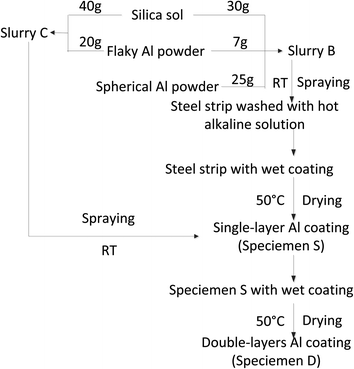
Both the steel sheet A and the sheet B described in Section 2.1 were used as metallic substrates in this work. Both sheets were polished with up to a 10 μm-SiC paper and cleaned with ethanol, soda solution and deionized water sequentially. In a typical preparation process of the coating (Fig. 1), some flaky Al powder of 7.000 g was first added to the commercial silica sol of 30.000 g and stirred thoroughly with a glass rod to make a slurry A at room temperature. After that 25.000 g of spherical Al powder was added to the slurry A and stirred thoroughly once again to obtain a slurry B at room temperature. Then slurry B was filled in a small aluminum alloy jar connected to a spraying gun. The slurry B was sprayed on the surface of one steel sheet by using the spraying gun driven by a pressurized air pump to make the first layer of Al coating (bottom coating). Then the coating was dried at 50 °C for one night. A specimen with a single-layer Al powder coating (denoted as specimen S) was thus obtained.In order to protect the wet coating from being destroyed by the operator hands and also dry the wet coating during the coating preparation, we made a hole with a diameter of 2 mm in the sheet center to hang the wet coating specimen with a metallic hook. After drying, the hole on the coated sheet was filled with the slurry B and then dried at 50 °C for one night. In this way, a specimen S without hole was thus prepared.
2.3 Preparation of double-layers specimen of Al powder coating
Some flaky Al powder of 20.000 g was added to a silica sol of 40.000 g and stirred thoroughly with a glass rod to make a slurry C at room temperature. The slurry C was sprayed on the surface of specimen S as before to make the second layer of Al coating (top coating) (Fig. 1). A specimen with double-layers of Al powder coating (denoted as specimen D) was thus prepared.2.4 Anti-corrosion test of coating specimens
A 3.5 wt% of NaCl solution (a simulated seawater) of 60 mL was put in a transparent plastic petri dish with a diameter of 85 mm and a depth of 13 mm. Then a specimen with or without coating was soaked completely in the aerated NaCl solution. The specimen was taken photos with a camera at different time during the whole soaking process. After a preset time, the specimen was taken out from the dish and washed with a flowing deionized water to remove the surface substances. After that, the specimen was dried with cool wind from an electric fan. Then the specimen was weighed. The thickness loss dD (μm) due to the corrosion of specimen during the soaking process was calculated as follows:39,40
 | (1) |
The corrosion rate Vc (μm per year) of the specimen was calculated as follows:39,40
 | (2) |
2.5 Electrochemical tests
The coating capacity for protecting the Q235 steel from being corroded in a 3.5 wt% of NaCl solution was assessed by the potentiodynamic polarization curves (Tafel curves) and the electrochemical impedance spectroscopy (EIS). A sheet of Q235 steel with a dimension of 10 mm in length, 10 mm in width and 3 mm in thickness was used. The two flat ends of the sheet along the length were first polished. One end was connected to a copper wire by soldering. The other end was exposed to air and put at the bottom of a plastic mold sealed by a plastic film. A liquid mixture composed of epoxy, ethylenediamine and dibutyl phthalate was poured in the plastic mold. After standing for 12 h, the liquid in the mold solidified. The resin on the end without copper wire was finally polished with a 0.04 μm-SiC paper and cleaned with ethanol and deionized water sequentially. After that, a required Al powder coating was made on the polished end as conducted before. In this way, a working electrode with coating was prepared. Electrochemical tests were performed at room temperature using an electrochemical workstation (CHI 660E, Chinstruments Co., Ltd., Shanghai, China). Tests were done in an aerated 3.5 wt% NaCl solution in a conventional three-electrode electrochemical cell setup. A coated sample, a platinum plate and a saturated calomel electrode (SCE) were used as working, auxiliary and reference electrode, respectively. Before starting the electrochemical tests, the samples were exposed to the NaCl solution for about 30 minutes to reach their open-circuit potentials. The potentiodynamic polarization curves (Tafel curves) were determined by some linear potentiodynamic positive sweep from −1.8 V to 0.2 V with a scanning rate of 5 mV s−1. The corrosion current density icorr, the corrosion potential Ecorr, the Tafel slopes of bc and ba, and the polarization resistance Rp were obtained from the potentiodynamic polarization curves based on the ASTM G59.41 The electrochemical impedance spectroscopy (EIS) measurements were done in 100 KHz to 0.01 Hz frequency range with an applied AC signal of 5 mV amplitude. The Zsimp Win 3.21 software was employed for fitting the EIS results. All the electrochemical tests were conducted at least three times to ensure the reproducibility of results.2.6 High temperature resistance of coatings
After heating at high temperature, the coatings tend to crack and peel on the carbon steel surface. Accordingly, the external O2 from air will penetrate along the cracks to contact the steel substrate and result in the oxidation of steel. Normally the steel specimen weight increases due to the oxidation. The specimen with or without coating was put in an alumina boat. The boat was then put in a Muffle furnace, which was connected to air with an alumina conduit, already set at 500 °C. After a preset time, the specimen was taken out from the furnace and cooled in the air. Then the specimen was weighed and taken photo. Thus, the thickness increase ΔD (μm) due to the oxidation of specimen calculated from the data obtained during the exposure time as follows:
 | (3) |
The oxidation rate Vo (μm per year) of the specimen was calculated as follows:
 | (4) |
2.7 Coating specimen characterization with XRD and SEM
The XRD patterns of the specimen coatings were recorded with a Rigaku TTRIII X-ray diffractometer equipped with a Cu Kα radiation source (λ = 0.15405 nm). The diffraction patterns of XRD were analyzed using the software of Crystallographic Search-Match. The Al powders and the coatings were observed with SEM (Zeiss EVO 18, special edition) and analyzed with affiliated energy-dispersive X-ray spectroscopy (EDS). In order to prevent the characterized aluminum powders from being sucked into the SEM vacuum system, either spherical or flaky Al powders was first dispersed in a drop of silica sol solution and then painted on a polished surface of a steel sheet of 10 × 10 mm to form a coating before the SEM observation. Some gold powder was then sprayed on the coating surface to increase the conductivity.2.8 Adhesive strength of coatings
The adhesive (pull-off) strength of the Al powder coatings were measured according to a China state standard (GB5210-1985).42 Briefly speaking, the test procedure was as follows. One flat end of the steel sheet B with a thickness of 11 mm without coating was painted with the binder B. The other end with Al powder coating was painted with one drop of liquid binder C. Then these two ends were pressed tightly with two steel molds with the same diameter as sheet B, respectively. Then they were dried at 30 °C for 1 h and then at 50 °C for 2 h. Then the two ends of two steel molds were fixed at the two pulling arms of one tensile test machine (Model 5105, MTS (SANS), USA). The stretching speed was fixed at 10 mm min−1. The adhesive strength P (MPa) of coating was calculated as follows:
 | (5) |
3. Results and discussion
3.1 Characterization of Al powders
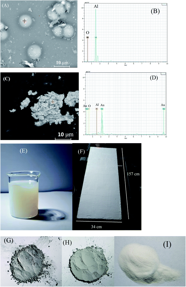
In order to prevent the characterized aluminum powders from being sucked into the SEM vacuum system, either spherical or flaky Al powders was first dispersed in a drop of silica sol solution and then painted on a polished surface of a steel sheet of 10 × 10 mm to form a coating before the SEM observation. Some gold powder was then sprayed on the coating surface to increase the conductivity. The SEM images of both spherical and flaky Al powders used in this work were presented in Fig. 2(A) and (C), respectively. The particle sizes of the spherical and the flaky Al powders were 6–9 μm and 4–9 μm, respectively (Fig. 2(A) and (C)). The EDS analysis indicated that no other elements other than Al and O were observed (Fig. 1(B) and (D)). The O peaks in EDS analysis (Fig. 2(B) and (D)) probably originate from the O element from the silica sol, which was confirmed by the later XRD characterization. It implied that the both metallic Al powders were pure.The silica sol used in this work was shown in Fig. 2(E). This commercial silica sol with a pH of 9.74 was more turbid than the ordinary one, which was specially used to stick metal powders such as zinc powder and aluminum powder according to the product specifics. It was odorless. It was reported that the silica sol can “glue” a range of chemically and physically diverse particles into the three-dimensional silica network formed upon gelation.43,44 Moreover, the particles ranging in size from 1 nm to tens of microns can be accommodated in the three-dimensional silica network.44 These explained why the spherical and the flaky Al powder particles ranging from 4 to 9 μm can be dispersed into the three-dimensional silica sol network in this work. The double-layers of Al powder coating on carbon steel Q235 surface was basically uniform and smooth (Fig. 2(F)). The unevenness of the steel substrate caused the slight unevenness of the coating (Fig. 2(F)). The flaky and spherical metallic Al powder were silver (Fig. 2(G)) and grey (Fig. 2(H)), respectively, while Al2O3 powder was white (Fig. 2(I)). It confirmed once again that the O peaks in EDS analysis (Fig. 2(B) and (D)) originated from the O element from the silica sol.
3.2 Anti-corrosion test of the specimens
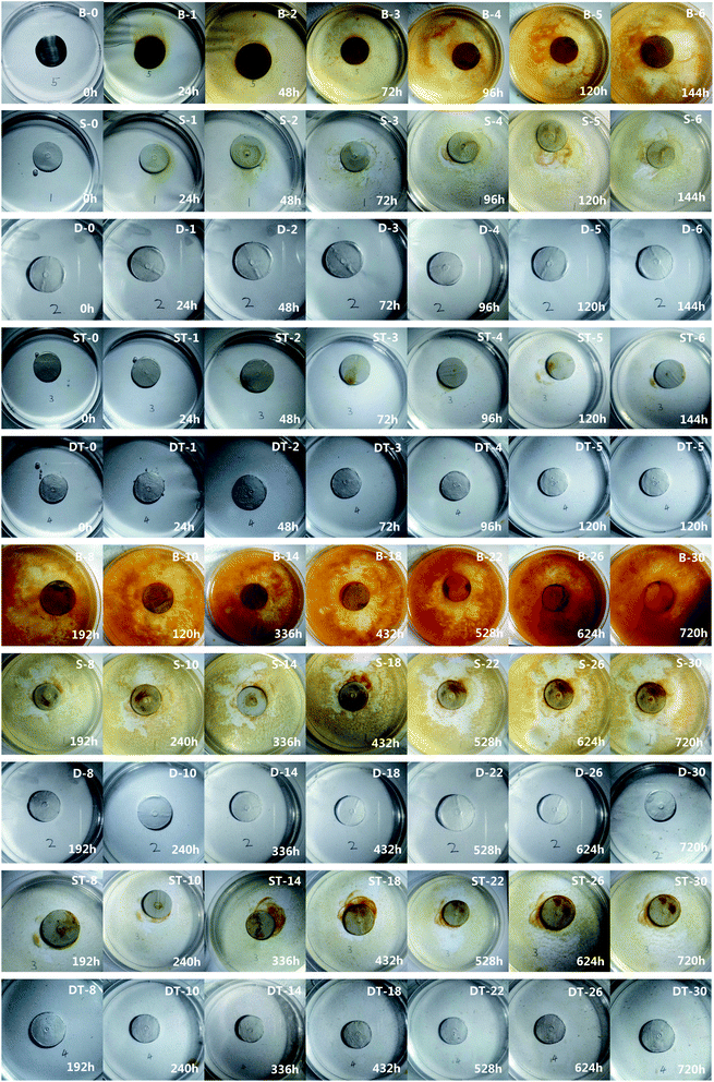
Both the single-layer and the double-layers coating specimens were placed in a Muffle furnace already set at 500 °C for 10 h. After that they were taken out of the furnace and cooled naturally in the air. The heated specimens were thus obtained and also used in the subsequent anti-corrosion tests. One polished Q235 steel sheet A free of coating was used as a control specimen and called coating-free specimen. Five types of specimens of coating-free, single-layer, heated single-layer, double-layers and heated double-layers were used in the corrosion test and the results were shown in Fig. 3 and 4. The corrosion test was performed by soaking the specimens in a 3.5 wt% of NaCl solution for 30 days (720 h) at room temperature.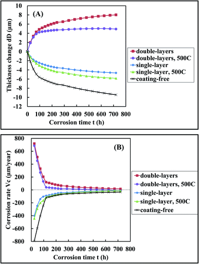 | ||
| Fig. 4 The variation of (A) the specimen thickness change dD and (B) the specimen corrosion rate Vc with corrosion time t when the specimens were soaked in the 3.5 wt% NaCl solutions, respectively. | ||
According to the corrosion extent, we divided the rust phenomena into two categories. When a small amount of yellow color appeared at the border of a specimen, we defined that a perceptible rust occurred. When a large amount of yellow color appeared at the border of specimen, we defined that a significant rust occurred. A perceptible rust occurred in 24 h, 24 h, 120 h for the coating-free specimen, the single-layer specimen and the heated single-layer specimen, respectively (Fig. 3). A significant rust occurred in 48 h, 120 h, 336 h for the coating-free specimen, the single-layer specimen and the heated single-layer specimen, respectively (Fig. 3). The weight change of the coating-free specimen, the single-layer specimen and the heated single-layer specimen were −1.28%, −1.04% and −0.59%, respectively, in 720 h (not shown), the corresponding specimen thickness change were −9.44 μm, −4.66 μm and −5.83 μm, respectively, in 720 h (Fig. 4(A)) and the corresponding specimen corrosion rates were −33 μm per year, −12 μm per year and −14 μm per year, respectively, in 720 h (Fig. 4(B)). These results indicated that the three specimens were corroded in 3.5 wt% NaCl solution during the soaking process of 720 h.
No rust was observed on the surface of the double-layers specimen and the heated double-layers specimen in 720 h (Fig. 3). The weight increase of the double-layers specimen and the heated double-layers specimen were 1.70% and 0.57%, respectively, in 720 h (not shown), the corresponding specimen thickness change were 8.02 μm and 5.03 μm, respectively, in 720 h (Fig. 4(A)) and the corresponding specimen corrosion rates were 17 μm per year and 0 μm per year, respectively, in 720 h (Fig. 4(B)). These results indicated that these two double-layers specimens didn't rust at all in 3.5 wt% NaCl solution in 720 h.
3.3 Electrochemical tests
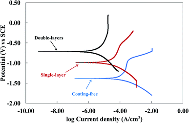
The potentiodynamic polarization curves (Tafel curves) of the coating free specimen, the single-layer specimen and the double-layers specimen were shown in Fig. 5. Because the potential was scanned in a positive direction for the three specimens, the cathodic corrosion current density was thus less than the corresponding anodic one only for the coating-free specimens according to the Zhang et al. report.45 Thus, the corrosion current densities of the coating free specimen, the single-layer specimen and the double-layers specimen were found to be 224 μA cm−2, 31 μA cm−2 and 5 μA cm−2, respectively, based on the Fig. 5 and the ASTM G59.41 The corrosion inhibition efficiency (IE) was defined as follows:
 | (6) |
![[thin space (1/6-em)]](https://www.rsc.org/images/entities/char_2009.gif) 770 Ω cm2, respectively, which were obtained based on the ASTM G59. The polarization resistance RP of a specimen is inversely proportional to the corrosion current density icorr.41 The larger the polarization resistance RP of a specimen, the larger the anti-corrosion ability of the specimen. Based on the polarization resistance RP, the anti-corrosion ability of the three specimens decreased in the following decreasing order: double-layers > single-layer > coating free.
770 Ω cm2, respectively, which were obtained based on the ASTM G59. The polarization resistance RP of a specimen is inversely proportional to the corrosion current density icorr.41 The larger the polarization resistance RP of a specimen, the larger the anti-corrosion ability of the specimen. Based on the polarization resistance RP, the anti-corrosion ability of the three specimens decreased in the following decreasing order: double-layers > single-layer > coating free.
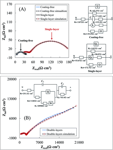
The electrochemical impedence spectroscopies of the coating free specimen, the single-layer specimen and the double-layers specimen were presented in Fig. 6. The charge transfer resistances Rct shown in the equivalent circuits for the coating free specimen, the single-layer specimen and the double-layers specimen were 29.3 Ω cm2, 172.7 Ω cm2 and 1283.0 Ω cm2, respectively (Fig. 6). The polarization resistance RPl for the coating free specimen might be calculated based on the resistance values of the corresponding equivalent circuit shown in Fig. 6(A).
 | (7) |
The polarization resistance RPl for the single-layer specimen might be calculated based on the resistance values of the corresponding equivalent circuit shown in Fig. 6(A).
 | (8) |
The polarization resistance RPl for the double-layers specimen might be calculated based on the resistance values of the corresponding equivalent circuit shown in Fig. 6(B). RPl = 1283 + 20![[thin space (1/6-em)]](https://www.rsc.org/images/entities/char_2009.gif) 900 + 763.4 = 22
900 + 763.4 = 22![[thin space (1/6-em)]](https://www.rsc.org/images/entities/char_2009.gif) 946.4 Ω cm2. In summary, the polarization resistance RPl for the coating free specimen, the single-layer specimen and the double-layers specimen were 8.1 Ω cm2, 30.5 Ω cm2 and 22
946.4 Ω cm2. In summary, the polarization resistance RPl for the coating free specimen, the single-layer specimen and the double-layers specimen were 8.1 Ω cm2, 30.5 Ω cm2 and 22![[thin space (1/6-em)]](https://www.rsc.org/images/entities/char_2009.gif) 946.4 Ω cm2, respectively (Table 1). Either the polarization resistance RPl or the charge transfer resistances Rct of the three specimens obtained from electrochemical impedence spectroscopies decreased in the following decreasing order: double-layers > single-layer > coating free (Table 1). It implied that the anti-corrosion ability of the three specimens decreased in the following decreasing order: double-layers > single-layer > coating free.
946.4 Ω cm2, respectively (Table 1). Either the polarization resistance RPl or the charge transfer resistances Rct of the three specimens obtained from electrochemical impedence spectroscopies decreased in the following decreasing order: double-layers > single-layer > coating free (Table 1). It implied that the anti-corrosion ability of the three specimens decreased in the following decreasing order: double-layers > single-layer > coating free.
| Specimens | Ecorr (V) | icorr (μA cm−2) | IE (%) | bc (mV dec−1) | ba (mV dec−1) | Rp (Ω cm2) | Rct (Ω cm2) | Rpl (Ω cm2) |
|---|---|---|---|---|---|---|---|---|
| Coating-free | −1.39 | 224 | 251 | 1468 | 415 | 29 | 8 | |
| Single-layer | −0.987 | 31 | 86 | 249 | 869 | 2723 | 173 | 31 |
| Double-layers | −0.718 | 5 | 98 | 432 | 867 | 21![[thin space (1/6-em)]](https://www.rsc.org/images/entities/char_2009.gif) 770 770 |
1283 | 22![[thin space (1/6-em)]](https://www.rsc.org/images/entities/char_2009.gif) 946 946 |
It was worthy noted that either the polarization resistance RPl or the charge transfer resistances Rct of the double-layers specimen was much higher than that of the single-layer specimen (Table 1). It implied that the top coating possessed a big resistance to inhabit the corrosion current. This big resistance originated from the fact that the compact top coating prevented the conductive salt water from contacting the steel substrate. Thus, the shielding effect of the compact top coating was the main anticorrosion mechanism of the double-layers coating.
3.4 XRD characterization
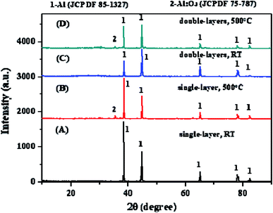
The XRD patterns of the single-layer specimen, the heated single-layer specimen, the double-layers specimen and the heated double-layers specimen were presented in Fig. 7. Only one metallic Al (JCPDF 85-1327) phase was found on the coating surfaces of both the single-layer and the single-layers specimens. It confirmed once again that both the spherical and the flaky Al powder were pure and the two coatings mainly consisted of metallic aluminum not alumina. When both the single-layer and the single-layers specimens were heated in the air at 500 °C for 10 h, a very small amount of Al2O3 (JCPDF 75-787) were formed on the both coating surfaces. It indicated that both the spherical and the flaky Al powder were rarely oxidized in the air at 500 °C for 10 h.3.5 SEM characterization
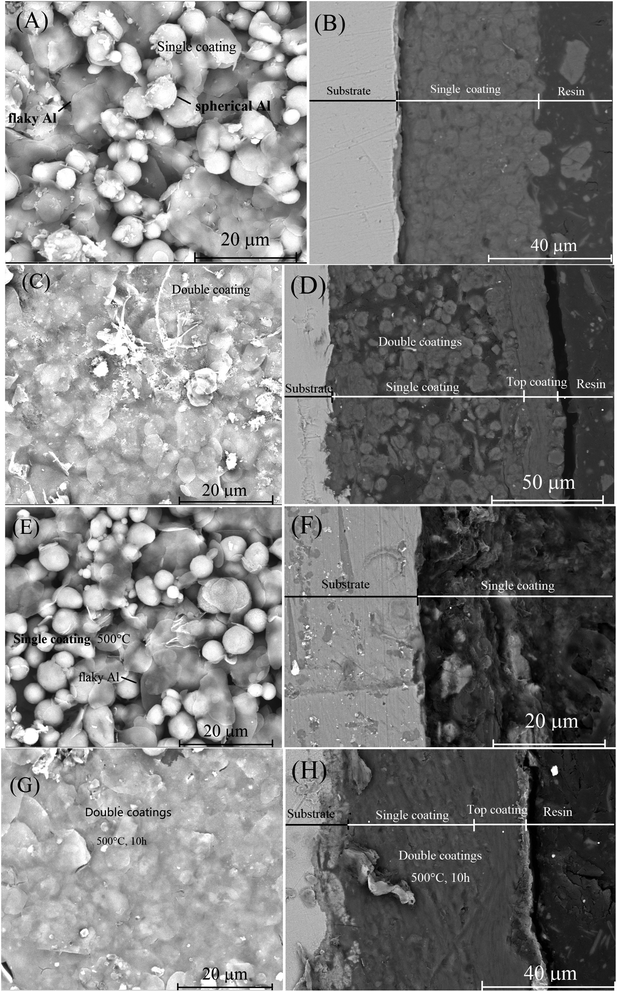
The SEM images of surface and cross-section of a single-layer specimen were presented in Fig. 8(A) and (B), respectively. Both spherical and flaky Al particles were found on the surface of the specimen (Fig. 8(A)). Some gaps between these spherical and flaky Al particles appeared on the specimen surface (Fig. 8(A)). These gaps might provide some accesses for external O2 and saline water to contact the internal steel substrate. It explained why the single-layer coating was susceptible to salt water corrosion. The thickness of the single-layer coating was about 47 μm (Fig. 8(B)). No cracks or voids were found in the interface between the steel substrate and the coating (Fig. 8(B)). However, many voids appeared inside the Al coating for the aluminized steel due to the high temperature process.24–26The SEM images of surface and cross-section of a double-layers specimen were presented in Fig. 8(C) and (D), respectively. The gaps between the flaky Al particles inside the top coating were much less than those between the Al particles inside the bottom coating (Fig. 8(C)). Actually, the top coating was made up of many superimposed flaky aluminum particles, no gaps between the particles can be observed inside the top coating based on the SEM image (Fig. 8(D)). It indicated the second top coating was much more compact than the first bottom coating. The presence of three-dimensional spherical Al particles in the first bottom layer resulted in more separate gaps between particles compared to the flat flaky Al particles in the top layer. The separate gaps led to less compact bottom layer than the top layer. The top coating therefore provided a good barrier against external salt water contacting the internal steel substrate. The thickness of the double-layers coating was about 97 μm (Fig. 8(D)). The thickness of the top coating was about 25 μm (Fig. 8(D)). Thus, the thickness of the bottom coating was about 72 μm (Fig. 8(D)). No cracks or voids were found in the interface between the top coating and the bottom coating. The presence of compact top coating likely explained why the double-layers coating exhibited excellent corrosion resistance to salt water. It implied that the coating compactness is the key to its anti-corrosion ability for the metallic aluminum coating.
The SEM images of surface and cross-section of the single-layer specimen heated at 500 °C for 10 h were presented in Fig. 8(E) and (F), respectively. No voids were formed inside the Al coating and no cracks were formed on the Al coating surface in this case. Perhaps this explained why the abilities of corrosion-resistance to salt water were similar for both the heated and the original single-layer specimens (Fig. 3 and 4).
The SEM images of surface and cross-section of the double layer coating specimen heated at 500 °C for 10 h were presented in Fig. 8(G) and (H), respectively. After the heating, the coating interior and surface didn't change noticeably. Perhaps this explained why the anti-corrosion abilities of both the heated and the original single-layer specimens were similar (Fig. 3 and 4).
3.6 High temperature resistance of coatings
After heating at high temperature, some ceramic coatings made of Al2O3 tend to crack and peel on the carbon steel surface, which was normally incurred by the mismatch in the thermal expansion coefficients between the ceramic coating and the steel substrate.46 In order to investigate the high temperature resistance of the coatings made in this work, a coating-free steel specimen, a single-layer Al coating specimen and a double-layers Al coating specimen were heated in the air at 500 °C for 15 h. The results were presented in Fig. 9 and 10. The initial polished coating-free steel specimen was bright (Fig. 9(A)). However, it completely became black after heating at 500 °C for 3 h due to the steel substrate oxidation (Fig. 9(A)). After 15 h, the weight of the coating-free steel specimen increased by 0.18% (not shown). The oxidation reaction between the external O2 and the steel substrate resulted in the weight increase of the steel sheet. The corresponding specimen thickness change due to the oxidation were 2.44 μm in 15 h (Fig. 10(A)) and the corresponding specimen oxidation rates were 367 μm per year at 15 h (Fig. 10(B)).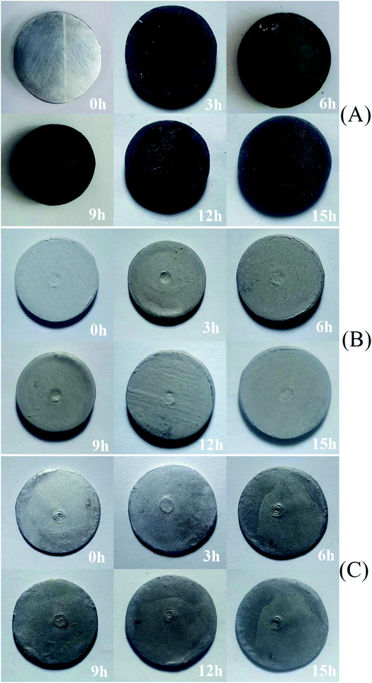 | ||
| Fig. 9 The photos of (A) the coating-free specimen, (B) the single-layer specimen, and (C) the double-layers specimen obtained when they were heated in the air at 500 °C at different time. | ||
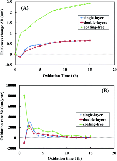 | ||
| Fig. 10 The variation of (A) the specimen thickness change ΔD and (B) the specimen oxidation rate Vo with oxidation time t when the specimens were heated in the air at 500 °C. | ||
The initial single-layer Al coating specimen was gray (Fig. 9(B)). After heating at 500 °C for 15 h, the coating didn't crack at all (Fig. 9(B)) and its weight increased by 0.13% (not shown). The corresponding specimen thickness change due to the oxidation were 0.66 μm in 15 h (Fig. 10(A)) and the corresponding specimen oxidation rates were 103 μm per year at 15 h (Fig. 10(B)).
The initial double-layers Al coating specimen was silver (Fig. 9(C)). After heating at 500 °C in the air for 15 h, the coating didn't crack at all (Fig. 9(C)) and its weight increased by 0.07% (not shown). The corresponding specimen thickness change due to the oxidation were 0.66 μm in 15 h (Fig. 10(A)) and the corresponding specimen oxidation rates were 93 μm per year at 15 h (Fig. 10(B)).
These results indicated that both the single-layer and the double-layers Al coatings resisted the possible crack or spall at 500 °C in the air at least for 15 h. As mentioned previously, both the spherical and flaky Al powders were hardly oxidized at 500 °C for 10 h based on the XRD characterization (Fig. 6). Thus, the thermal expansion coefficients of the both coatings were likely close to the substrate steel even heated at 500 °C in the air for 15 h. This might explain why the both coatings didn't crack at all when they were heated at 500 °C in the air for 15 h. A commercial hot-dipped 55% Al–43.5% Zn–1.5% Si coating (Galvalume coating47) cracked after heated at 400 °C for 24 h and spalled from the steel substrate with a thickness of 0.8 mm after heated at 450 °C for 24 h.48 Thus, it seems that the pure metallic aluminum coating prepared in this work had better performance for resisting the crack at high temperature than that of the commercial hot-dipped 55% Al–43.5% Zn–1.5% Si coating.
The oxidation of steel substrate was reduced by 73% ((2.44 μm–0.66 μm)/2.44 μm) based on the specimen thickness change when a coating-free steel specimen was change to a single-layer Al coating specimen or a double-layers Al coating specimen. The oxidation of steel substrate were reduced by 72% ((367 μm per year–103 μm per year)/367 μm per year) and 75% ((367 μm per year–93 μm per year)/367 μm per year) based on the specimen oxidation rate at 15 h when a coating-free steel specimen was change to a single-layer specimen and a double-layers specimen, respectively. These indicated that both the single-layer and the double-layers Al coatings effectively prevented steel substrate from being oxidized at 500 °C for 15 h in the air.
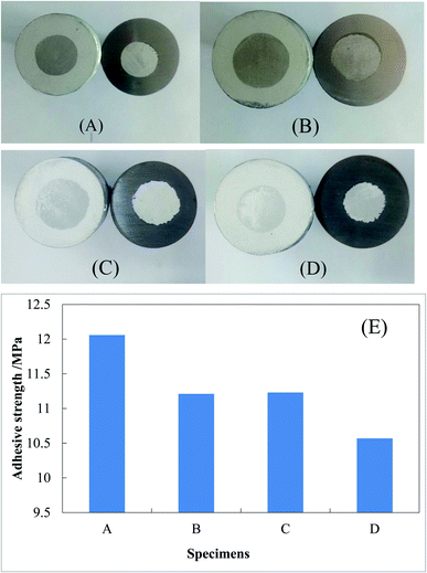
3.7 Adhesive strength of coatings
The photos from the pull-off experiments for determining the adhesive strengths of were shown in Fig. 11(A)–(D). The adhesive strengths of the single-layer and double-layers Al coating specimens were 12.06 MPa and 11.23 MPa, respectively (Fig. 11(E)). After heating at 500 °C in the air for 15 h, the adhesive strengths of the single-layer and double-layers specimens fell to 11.21 MPa and 10.57 MPa, respectively (Fig. 11(E)). Thus, the heating treatment at 500 °C resulted in the decrease of the coating adhesive strength. However, it was found that a thin Al–Fe alloy layer free of voids between the Al coating and the steel substrate was formed by heating the single-layer specimen at 800 °C and cooling it slowly, and the adhesive strength was thus increased from 12.06 MPa to 15.50 MPa (not shown). In the petrochemical industry, epoxy coatings are often used to protect the inner wall of oil and gas steel pipelines from corrosion.49–51 It was reported that the adhesive strengths of the epoxy coatings on the steel Q235 were normally between 2 and 8 MPa depending on many experimental conditions.52 The shear bond strength of the epoxy coatings on the steel Q235 were normally between 2 and 14 MPa depending on the pretreatment conditions of steel surface.53 Thus, the adhesive strengths of the single-layer and double-layers inorganic anti-corrosive coatings of metallic Al on steel Q235 were larger than those of the ordinary organic anti-corrosive coatings of epoxy. Thus, these single-layer and double-layers Al coating specimens can be applied in the industries from the point view of adhesive strength of coating.4. Discussions
In the most popular improved Sendzimir hot-dipping Al process, the steel strip is first sent into a heating furnace at a temperature about 1100 °C with a non-oxidation atmosphere, and the oil stain on the surface of the steel piece is carbonized or changed to a form that is easily removed in subsequent steps. Then the steel piece is sent into a heating furnace at a temperature about 800 °C in a reducing atmosphere of H2 plus N2 to remove the oxide film on the surface. Finally, the steel piece free of oxide scale is put into a molten aluminum solution for dip plating at a temperature about 750 °C in a protective reducing atmosphere.In our work, all above high temperature processes can be eliminated. The usual pickled cold rolled steel strip was first washed with hot alkaline solution and then washed with clean water, a clean steel strip was thus obtained. The clean steel strip can directly be used as the raw material in our work, because our Al coating does not have such strict requirements on the cleanliness of the steel strip as the Sendzimir hot-dipping Al process. The above cleaned steel strip will be passed through an aqueous slurry bath containing fine Al powders at room temperature for one minute and then dried at 50 °C for about 8 h and a metallic Al coating was thus formed based on this novel method. The whole process was much simpler than that of the improved Sendzimir hot-dipping Al and suitable for continuous industrial production. Thus, this novel process has the potential to be scaled up to an industrial scale.
The Al-coatings thus obtained in this work had an average adhesive strength of 11–12 MPa, which was much larger than the corresponding value of an ordinary anti-rusting epoxy coating on Q235 (max 8 MPa). A thin Al–Fe alloy layer free of voids can be formed by heating the single-layer Al coating at 800 °C for a few minutes and then cooling the coating slowly. The coating adhesive strength were thus increased to 15–16 MPa (not shown in this work). Thus, this is a revolutionary novel method to manufacture metallic Al coating on steel. In addition, some hazardous fluorides or chlorides and explosive H2 were involved in the traditional hot-dipping Al methods. All these materials can be eliminated in our method. Thus, this method was a green process.
The thickness of steel strips used in continuous hot-dipping Al or Zn were always less than 0.8 mm in order to adapt to large-scale continuous annealing and H2 reduction industrial production. However, our method had no limitation to the thickness of steel plates to be coated, as long as the they can be soaked in the aqueous Al powder slurry.
For large and complex steel structure containing anti-corrosion coating near sea, our method can be used for in situ coating. This is especially important for the large steel components Zn or Al-coating damaged by high temperature welding or the damaged Zn or Al-coating caused by the use for many years.
The voids inside the Al coating formed during the aluminized process can be avoided in this work and the porosity of the Al coating made in this work was thus smaller than that of the aluminized process. In addition, some surface defects such as missing plating, dummy plating and pinholes for the hot-dipping aluminum method due to the high operation temperatures can be reduced by using this novel method. Thus, the Al coating made by this method had better seawater corrosion resistance than that of the hot-dipped aluminum or the aluminized process.
In summary, compared to the conventional hot-dipping aluminum or aluminized process, this novel method eliminates all the high temperature processes and thus saves a lot of energy, eliminates the use of all hazardous fluorides or chlorides and explosive H2, avoids the formation of the voids inside aluminized coating, reduces the hot-dipped Al coating defects, can be applied for the steel plates over 0.8 mm thickness, can be applied to repair in situ the damaged Al or Zn coatings.
5 Conclusion
A silica sol was added with a solid mixture of a spherical Al powder (77 wt%) and a flaky Al powder (23 wt%) to make a slurry A. The slurry A was sprayed on the steel Q235 and then dried at 50 °C overnight to make the bottom coating (single-layer specimen). After that the silica sol was mixed with only flaky Al powder to make a slurry B. The slurry B was sprayed on the dried bottom coating surface and then dried at 50 °C overnight to make the top coating (double-layers specimen). When the single-layer and double-layers specimens were heated at 500 °C for 10 h, two heated single-layer and double-layers specimens were obtained, respectively. The following conclusions can be drawn from this work.(1) When soaked in 3.5 wt% of NaCl solution, the coating-free specimen, the single-layer specimen and the heated single-layer specimen showed a perceptible light rust in 24 h, 24 h, and 120 h, respectively, and the specimen thickness variation were −9.44 μm, −4.66 μm and −5.83 μm, respectively, in 720 h and the specimen corrosion rates were −33 μm per year, −12 μm per year and −14 μm per year, respectively, at 720 h for the three specimens. However, no rust was observed for the double-layers and the heated double-layers specimens in 720 h (or 30 days) and the corresponding specimen thickness change were 8.02 μm and 5.03 μm, respectively, at 720 h and the corresponding specimen corrosion rates were 17 μm per year and 0 μm per year, respectively, at 720 h. It indicated that the only both double-layers specimens had the ability to resist the seawater corrosion in 30 days.
(2) According to the potentiodynamic polarization curves, the corrosion potentials Ecorr of the coating free specimen, the single-layer specimen and the double-layers specimen were −1.39 V, −0.987 V and −0.718 V, respectively, and the corresponding corrosion current densities icorr were 224 μA cm−2, 31 μA cm−2 and 5 μA cm−2, respectively and the corresponding polarization resistances RP were 415 Ω cm2, 2723 Ω cm2 and 21![[thin space (1/6-em)]](https://www.rsc.org/images/entities/char_2009.gif) 770 Ω cm2, respectively. According to the electrochemical impedence spectroscopies, the charge transfer resistances Rct for the coating free specimen, the single-layer specimen and the double-layers specimen were 29.3 Ω cm2, 172.7 Ω cm2 and 1283.0 Ω cm2, respectively and the corresponding polarization resistances RPl were 8.1 Ω cm2, 30.5 Ω cm2 and 22
770 Ω cm2, respectively. According to the electrochemical impedence spectroscopies, the charge transfer resistances Rct for the coating free specimen, the single-layer specimen and the double-layers specimen were 29.3 Ω cm2, 172.7 Ω cm2 and 1283.0 Ω cm2, respectively and the corresponding polarization resistances RPl were 8.1 Ω cm2, 30.5 Ω cm2 and 22![[thin space (1/6-em)]](https://www.rsc.org/images/entities/char_2009.gif) 946.4 Ω cm2, respectively. The anti-corrosion ability of the three specimens based on the electrochemical studies decreased in the following decreasing orders: double-layers > single-layer > coating-free. The shielding effect was the main anticorrosion mechanism of the double-layers coating.
946.4 Ω cm2, respectively. The anti-corrosion ability of the three specimens based on the electrochemical studies decreased in the following decreasing orders: double-layers > single-layer > coating-free. The shielding effect was the main anticorrosion mechanism of the double-layers coating.
(3) The thickness of the prepared single-layer coating specimen was about 47 μm. The thicknesses of bottom and top coatings were about 72 μm and 25 μm, respectively, for the prepared double-layers coating specimen. Only one metallic Al phase was found on the coating surfaces of the single-layer and double-layers specimens based on the XRD characterization. When the both specimens were heated in the muffle furnace at 500 °C for 10 h in the air, only a very small amount of Al2O3 phase was formed on their coating surfaces. It indicated that both the spherical and the flaky Al particles were hardly oxidized at 500 °C for 10 h in the air. After heated at 500 °C for 15 h, the coating free specimen, the single-layer specimen and the double-layers specimen showed a thickness increase of 2.44 μm, 0.66 μm and 0.66 μm, respectively, and an oxidation rate of 367 μm per year, 103 μm per year and 93 μm per year, respectively. Both the single-layer and the double-layers coatings didn't crack at all after heated at 500 °C for 15 h. The oxidation rate of specimen at 15 h were reduced by 72% and 75% when a coating-free specimen was change to a single-layer specimen and a double-layers specimen, respectively. These indicated that both the single-layer and the double-layers Al coatings effectively prevented steel substrate from being oxidized at 500 °C for 15 h in the air.
(4) The average adhesive strengths of the single-layer and the double-layers Al coating on steel Q235 were 12.06 MPa and 11.23 MPa, respectively, which were larger than those of the ordinary organic anti-corrosive coatings of epoxy. After heating at 500 °C for 15 h, the adhesive strengths of the single-layer and double-layers specimens fell to 11.21 MPa and 10.57 MPa, respectively.
Conflicts of interest
The authors declare no conflict of interest.Acknowledgements
This work was supported by Fundamental Research Funds for the Central Universities (FRF-MP-20-03) (China).References
- P. Elliott, A. A. Ansari, R. Prescott and M. F. Rothman, Corrosion, 1988, 44, 544–554 CrossRef CAS.
- G. W. Meetham, J. Mater. Sci., 1991, 26, 853–860 CrossRef CAS.
- G. Y. Lai, JOM, 1991, 43, 54–60 CrossRef CAS.
- C.-C. Tsaur, J. C. Rock and Y.-Y. Chang, Mater. Chem. Phys., 2005, 91, 330–337 CrossRef CAS.
- H.-H. Liu, W.-J. Cheng and C.-J. Wang, Appl. Surf. Sci., 2011, 257, 10645–10652 CrossRef CAS.
- C.-J. Wang and Y.-C. Chang, Mater. Chem. Phys., 2002, 76, 151–161 CrossRef CAS.
- W.-J. Cheng and C.-J. Wang, Surf. Coat. Technol., 2009, 204, 824–828 CrossRef CAS.
- S. Kobayashi and T. Yakou, Control of intermetallic compound layers at interface between steel and aluminum by diffusion-treatment, Mater. Sci. Eng., A, 2002, 338, 44–53 CrossRef.
- Y. Chang, C. C. Tsaur and J. C. Rock, Surf. Coat. Technol., 2006, 200, 6588–6593 CrossRef CAS.
- J. Sun and M.-P. Wan, Modern Machinery, 2010, 2, 75–77 Search PubMed , (in Chinese).
- C.-L. Liu, Y.-P. Li, G.-Q. Yu, Y.-L. Wang and Q.-F. Zhang, Steel rolling, 2016, 33, 50–54 Search PubMed , (in Chinese).
- T.-B. Wei, Wisco Technology, 1999, 37, 48–53 Search PubMed , (in Chinese).
- X. Li, H.-R. Li, T. Ma, M. X. Li, H.-B. Zhang and Y.-G. Li, Hot Working Technology, 2019, 48, 19–22 Search PubMed , (in Chinese).
- H. Springer, A. Kostka, E. J. Payton, D. Raabe, A. Kaysser-Pyzalla and G. Eggeler, Acta Mater., 2011, 59, 1586–1600 CrossRef CAS.
- F.-C. Yin, M.-X. Zhao, Y.-X. Liu, W. Han and Z. Li, Trans. Nonferrous Met. Soc. China, 2013, 23, 556–561 CrossRef CAS.
- X. Wu, D. Weng, S. Zhao and W. Chen, Surf. Coat. Technol., 2005, 190, 434–439 CrossRef CAS.
- Z. D. Xiang, S. Rose and P. K. Datta, 3rd International Conference on Surface Engineering, Chengdu, China, 2002, pp. 306–310 Search PubMed.
- Y. Q. Wang, Y. Zhang and D. A. Wilson, Surf. Coat. Technol., 2010, 204, 2737–2744 CrossRef CAS.
- Z. Zhou, F. Xie and J. Hu, Surf. Coat. Technol., 2008, 203, 23–27 CrossRef CAS.
- B. L. Bates, Y. Q. Wang, Y. Zhang and B. A. Pint, Surf. Coat. Technol., 2009, 204, 766–770 CrossRef CAS.
- R. S. Dutta, S. Majumdar, A. Laik, K. Singh, U. D. Kulkarni, I. G. Sharma and G. K. Dey, Surf. Coat. Technol., 2011, 205, 4720–4725 CrossRef CAS.
- S. Guo, Z. B. Wang and K. Lu, J. Mater. Sci. Technol., 2015, 31, 1268–1273 CrossRef CAS.
- Z. Zhan, Z. Liu, J. Liu, L. Li, Z. Li and P. Liao, Appl. Surf. Sci., 2010, 256, 3874–3879 CrossRef CAS.
- W. Zhang, J.-B. Wen, Y.-Q. Long and Z.-K. Fang, Trans. Mater. Heat Treat., 2005, 26(4), 106–110 CAS , (in Chinese).
- Y. Ding, W.-J. Wei and Y.-Z. Zhou, J. Mater. Prot., 2001, 34(10), 17–18 CAS , (in Chinese).
- W. Zhang, J.-B. Wen, Y.-Q. Long, J.-M. Wang and Z.-K. Fang, Trans. Mater. Heat Treat., 2004, 25(6), 96–100 CAS , (in Chinese).
- R. Arabi Jeshvaghani, M. Emami, O. Shafiee and H. R. Shahverdi, Surf. Coat. Technol., 2014, 240, 365–372 CrossRef CAS.
- S.-E. Wulf, N. Holstein, W. Krauss and J. Konys, Fusion Eng. Des., 2013, 88, 2530–2534 CrossRef CAS.
- Q. X. Liu, S. Z. El Abedin and F. Endres, Surf. Coat. Technol., 2006, 201, 1352–1356 CrossRef CAS.
- X.-B. Zhang, X. Chang, F.-H. Han and W.-J. Huang, Adv. Mater. Res., 2012, 472–475, 2775–2778 CAS.
- R. M. H. Pombo Rodriguez, R. S. C. Paredes, S. H. Wido and A. Calixto, Surf. Coat. Technol., 2007, 202, 172–179 CrossRef.
- E. A. Esfahani, H. Salimijazi, M. A. Golozar, J. Mostaghimi and L. Pershi, J. Therm. Spray Technol., 2012, 21, 1195–1202 CrossRef.
- J.-X. Zhou, M.-C. Yang, R.-Q. Wang and X.-M. Pang, Surf. Coat. Technol., 2017, 330, 53–60 CrossRef CAS.
- W. Li, R.-R. Jiang, C.-J. Huang, Z.-H. Zhang and Y. Feng, Mater. Des., 2015, 65, 757–761 CrossRef CAS.
- A. Moridi, S. M. Hassani-Gangaraj, M. Guagliano and M. Dao, Surf. Eng., 2014, 36, 369–395 CrossRef.
- N. Li, W.-Y. Li, X.-W. Yang, N. D. Alexopoulos and P.-L. Niu, Mater. Corros., 2017, 68, 546–551 CrossRef CAS.
- I. Peter, B. Aldwell, R. Lupoi and M. Rosso, International thermal spray conference, Shanghai, 2016 Search PubMed.
- F. S. da Silva, J. Bedoya, S. Dosta, N. Cinca, I. G. Cano, J. M. Guilemany and A. V. Benedetti, Corros. Sci., 2017, 114, 57–71 CrossRef.
- Y.-T. Ma, Y. Li and F.-H. Wang, Corros. Sci., 2010, 52, 1796–1800 CrossRef CAS.
- C. Pan, W. Han and Z.-Y. Wang, et al., J. Mater. Eng. Perform., 2016, 25, 5382–5390 CrossRef CAS.
- ASTM G59 – 97 (Reapproved 2014), Standard Test Method for Conducting Potentiodynamic Polarization Resistance Measurements, 2014.
- GB5210-1985 (China state standard), Determination of adhesion of coats: Pull-off test, 1985.
- C. A. Morris, M. L. Anderson, R. M. Stroud, C. I. Merzbacher and D. R. Rolison, Science, 1999, 284, 622–624 CrossRef CAS.
- R. Stroud, Silica sol as “Nanoglue”, American Physical Society, Annual March Meeting, Minneapolis, 2002 Search PubMed.
- X.-L. Zhang, Z.-H. Jiang, Z.-P. Yao, Y. Song and Z.-D. Wu, Corros. Sci., 2009, 51, 581–587 CrossRef CAS.
- P. Song, J.-S. Lu, J.-G. Lu and D.-F. Zhang, Rare Met. Mater. Eng., 2010, 39, 613–617 CAS.
- H. E. Townsend and A. R. Borzzillo, Mater. Perform., 1996, 35, 30–36 CAS.
- N.-M. Wen and Y.-L. Ren, Mater. Mech. Eng., 2018, 42(5), 32–34 Search PubMed , (in Chinese).
- H. Guo, Y.-D. Huang, L.-H. Meng, L. Liu, D.-P. Fan and D.-X. Liu, Mater. Lett., 2009, 63, 1531–1534 CrossRef CAS.
- C.-C. Wang, H.-T. Cheng, Y. Xian, G. Wang and S.-B. Zhang, Trans. Chin. Soc. Agric. Eng., 2017, 33, 281–287 CAS.
- M. Conradi, A. Kocijan, M. Zorko and I. Verpoest, Appl. Surf. Sci., 2015, 80, 20–26 CAS.
- Z. Zhai and L.-J. Feng, Prog. Org. Coat., 2019, 131, 36–41 CrossRef CAS.
- S.-Q. Han, Z.-N. Liu, J. Liu, H.-B. Zhang, Y.-H. Li and X.-L. Fan, J. Liaoning Univ. Pet. Chem. Technol., 2009, 29, 55–57 CAS.
| This journal is © The Royal Society of Chemistry 2021 |

