 Open Access Article
Creative Commons Attribution 3.0 Unported Licence
Li–fluorine codoped electrospun carbon nanofibers for enhanced hydrogen storage†
Xiaohong Chen a,
Zhiyong Xuea,
Kai Niub,
Xundao Liuc,
Wei lva,
Bao Zhanga,
Zhongyu Lia,
Hong Zenga,
Yu Rena,
Ying Wu*a and
Yongming Zhang*b
aInstitute of Advanced Materials, North China Electric Power University, Beijing, China. E-mail: yingwu2000@hotmail.com
bSchool of Chemistry and Chemical Engineering, Shanghai Jiao Tong University, No. 800 Dongchuan Rd., Minhang District, Shanghai 200240, China. E-mail: ymzsjtu@gmail.com
cSchool of Materials Science and Engineering, University of Jinan, Jinan, 250022 China
First published on 20th January 2021
Abstract
Carbon materials have attracted increasing attention for hydrogen storage due to their great specific surface areas, low weights, and excellent mechanical properties. However, the performance of carbon materials for hydrogen absorption is hindered by weak physisorption. To improve the hydrogen absorption performance of carbon materials, nanoporous structures, doped heteroatoms, and decorated metal nanoparticles, among other strategies, are adopted to increase the specific surface area, number of hydrogen storage sites, and metal catalytic activity. Herein, Li–fluorine codoped porous carbon nanofibers (Li–F–PCNFs) were synthesized to enhance hydrogen storage performance. Especially, perfluorinated sulfonic acid (PFSA) polymers not only served as a fluorine precursor, but also inhibited the agglomeration of lithium nanoparticles during the carbonization process. Li–F–PCNFs showed an excellent hydrogen storage capacity, up to 2.4 wt% at 0 °C and 10 MPa, which is almost 24 times higher than that of the pure porous carbon nanofibers. It is noted that the high electronegativity gap between fluorine and lithium facilitates the electrons of the hydrogen molecules being attracted to the PCNFs, which enhanced the hydrogen adsorption capacity. In addition, Li–F–PCNFs may have huge potential for application in fuel cells.
Introduction
Hydrogen has attracted increasing attention as an environmentally safe energy source, and with great potential for application in powered vehicles.1,2 In recent decades, significant efforts to find new hydrogen storage materials have been made, such as metal alloys, complex hydrides, metal–organic frameworks, carbon materials, etc.3–15 Interestingly, carbon-based materials, with their low cost and weight, have long been considered as suitable adsorption substrates for the reversible storage of hydrogen. Yang reported that the hydrogen gas uptake of a multiwalled carbon nanotube is only 0.21 wt% at 77 K and 1 bar.16 Furthermore, Bai showed that the maximum hydrogen storage of carbon nanofibers is 0.65 and 0.6 wt% H2 respectively, at 330 K and 9 MPa.17,18 However, a series of carbon-based materials (such as carbon fibers, graphene and carbon nanotubes) show a moderate performance,19–23 which is attributed to the weak physisorption between molecular hydrogen and carbon-based materials.24–26To increase the physisorption-based storage capability, large surface areas,27,28 heteroatom doping29–34 and alkali metal loading35–38 of carbon-based materials are highly desired. High specific surface areas and appropriate pore sizes significantly improve hydrogen molecule adsorption, which could be fulfilled by nanoporous carbon structures.39 Kou's group focused on issue-oriented schemes for activating the electrospun CNFs in terms of enhancing the conductivity, modulating the pore configuration, and doping with heteroatoms, among others, in close reference to some applications in supercapacitors and hydrogen storage.40–46 Moreover, Cheng reported fluorine doped graphite intercalation compounds enhanced hydrogen adsorption, because of the donation of electron density from the fluorine atom to the H2 antibonding σ* orbital.47–50 Meanwhile, Pinkerton showed a high hydrogen absorption capacity of 1.3 wt%, when alkali metals were introduced into carbon materials.51 Using porous carbon materials, heteroatoms or alkali metals alone, the hydrogen storage capacity has been limited. Therefore, heteroatoms and alkali metals were co-introduced to porous carbon-based hydrogen storage materials to improve the hydrogen adsorption capacity.
Herein, we explore an easy and facile strategy to obtain Li–fluorine codoped porous carbon nanofibers (Li–F–PCNFs) for a higher hydrogen adsorption, prepared through electrospun, hydrothermal and calcination methods. More interestingly, Li–F–PCNFs not only afford more defect sites, but support fluorine and uniformly dispersed alkali metal dopants. Thus, the excellent hydrogen storage capacity of Li–F–PCNFs is expected to be obtained by the synergistic effect among these three factors.
Experimental
Materials
Polyvinylpyrrolidone (PVP; Mw = 300![[thin space (1/6-em)]](https://www.rsc.org/images/entities/char_2009.gif) 000) was bought from Aldrich Co., Ltd. Polyacrylonitrile (PAN; Mw = 1
000) was bought from Aldrich Co., Ltd. Polyacrylonitrile (PAN; Mw = 1![[thin space (1/6-em)]](https://www.rsc.org/images/entities/char_2009.gif) 500
500![[thin space (1/6-em)]](https://www.rsc.org/images/entities/char_2009.gif) 000) was purchased from J&K scientific Chemical Co., Ltd. Lithium hydroxide (LiOH) was gotten from Alfa Aesar Co., Ltd. Perfluorinated sulfonic acid (PFSA) resin solution (IEC = 1.1) was obtained from Dongyue Co., Ltd. Ethanol was gotten from Shanghai Lingfeng Chemical Reagent Co. Ltd. N,N-Dimethylformamide (DMF) was provided by Sinopharm Chemical Reagent Co., Ltd. Those solvents were all of analytical grade and used as received.
000) was purchased from J&K scientific Chemical Co., Ltd. Lithium hydroxide (LiOH) was gotten from Alfa Aesar Co., Ltd. Perfluorinated sulfonic acid (PFSA) resin solution (IEC = 1.1) was obtained from Dongyue Co., Ltd. Ethanol was gotten from Shanghai Lingfeng Chemical Reagent Co. Ltd. N,N-Dimethylformamide (DMF) was provided by Sinopharm Chemical Reagent Co., Ltd. Those solvents were all of analytical grade and used as received.
Apparatus
The morphology of the PCNFs, F–PCNFs, and Li–F–PCNFs composites was characterized by transmission electron microscopy (TEM) and scanning electron microscopy (SEM) using JEM-2010HT and JEOL2100F (both from Electron Optics Laboratory Co., Ltd., Japan), respectively. FT-IR was recorded on a Perkin Elmer spectrum 100 FTIR spectrometer. Powder X-ray diffraction (XRD) analyses were performed on a diffractometer (Bruker, German, APLX-DUO) with Cu Kα radiation. Raman spectra were recorded using a Thermo Fisher H31XYZE-US with an excitation wavelength of 532 nm. The specific surface area of the sample was calculated by the Brunauer–Emmett–Teller (BET) equation (Quantachrome Instruments version 11.02, America). Hydrogen storage properties were tested by a full-automatic PCI monitor apparatus (Suzuki, Japan, Shokan Co., Ltd.)Synthetic procedures
For comparison, pristine PCNFs were also fabricated under the same conditions, without PFSA in the precursor solution. In addition, LiOH (2 wt%) was added to the hydrothermal treatment, and a series of Li–F–PCNFs composites (0.01Li–F–PCNFs, 0.05Li–F–PCNFs and 0.1Li–F–PCNFs) was finally obtained according to the above F–PCNFs procedure.
Hydrogen storage capability measurements
The hydrogen adsorption properties of the samples, with a typical amount of around 150 mg, were conducted in a conventional Sieverts-type apparatus (Suzuki, PCT-1SPWIN, Japan). The hydrogen adsorption rate measurements were performed at 0 °C with a pressure of 10 MPa. Before the measurements, the samples were degassed under vacuum at 300 °C for at least 10 h.Results and discussion
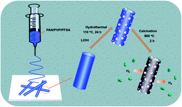
The overall synthetic procedure for the Li–F–PCNFs composites is illustrated in Fig. 1. PAN/PVP/PFSA nanofibers were first obtained via electrospinning of the mixture of PAN, PVP and PFSA in DMF solution. After removing PVP and exchanging the Li ion by a hydrothermal method and then drying, porous PAN/PFSA–Li nanofibers were preoxidized and carbonized at 220 and 900 °C under argon, respectively, yielding the resulting Li–F–PCNFs composites.In order to validate that the –SO3H successfully converted to –SO3Li from PFSA, FT-IR spectra of the PAN/PVP/PFSA and porous PAN/PFSA–Li nanofibers were conducted and are shown in Fig. 2. The characteristic peak of sulfonate (–SO3H) groups at 1052 cm−1 of PAN/PVP/PFSA is absent after hydrothermal treatment. Meanwhile, the emerging peak at 1063 cm−1 associated with –SO3–Li is observed, indicating SO3–H successfully converted into the SO3–Li of PFSA.54,55
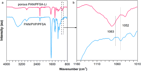 | ||
| Fig. 2 (a) FT-IR spectra and (b) a magnified view of the spectra of PAN/PVP/PFSA and porous PAN/PFSA–Li. | ||
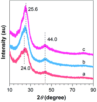
To further demonstrate the successful preparation of the composites, XRD analysis was conducted. As can be seen from Fig. 3a, two broad peaks located at around 24.0 and 44.0° are evident for F–CNFs, which can be attributed to the graphite (002) and (004) crystalline plane with a hexagonal structure. Furthermore, with fluorine doping and lithium incorporation, the broad diffraction peak at 24.0° became redshifted to a sharp diffraction peak at 25.6°, indicating the graphitization degree enhancement of the 0.1Li–F–PCNFs composites, which is caused by the formation of Li nanoparticles (Li NPs) and fluorine doping on the surface of PCNFs (Fig. 3b and c). Meanwhile, the diffraction peaks from 0.01F–PCNFs, 0.05F–PCNFs, 0.01Li–F–PCNFs, and 0.05Li–F–PCNFs composites show a similar phenomenon, which further verifies the cooperation among fluorine and lithium factors (Fig. S1†). This is evident from the diffraction pattern of the resulting Li–F–PCNFs composites. However, the weak signals of Li NPs are most likely because of its low crystallinity.
Morphologies of PCNFs and their corresponding composites were further revealed by SEM observation. PAN/PVP and PAN/PVP/PFSA nanofibers exhibit smooth surfaces (Fig. S2, S3 and S6†), after removing PVP through a hydrothermal method. Porous PAN and PAN/PFSA nanofibers show many nanopores and rough surfaces (Fig. 4a and c, S4 and S7†). Meanwhile, some LiOH nanoparticles are also evenly dispersed on the porous PAN/PFSA–Li surface, after the ion exchange between Li+ and H+ ions of PFSA (Fig. 4e, S9 and S11†). After being carbonized, PCNFs and F–PCNFs exhibit rough surfaces with diameters ranging from 150 to 250 nm (Fig. 4b and d, S5 and S8†), such nanopores can provide more active sites for further alkali metal nanoparticles deposition and high hydrogen storage.
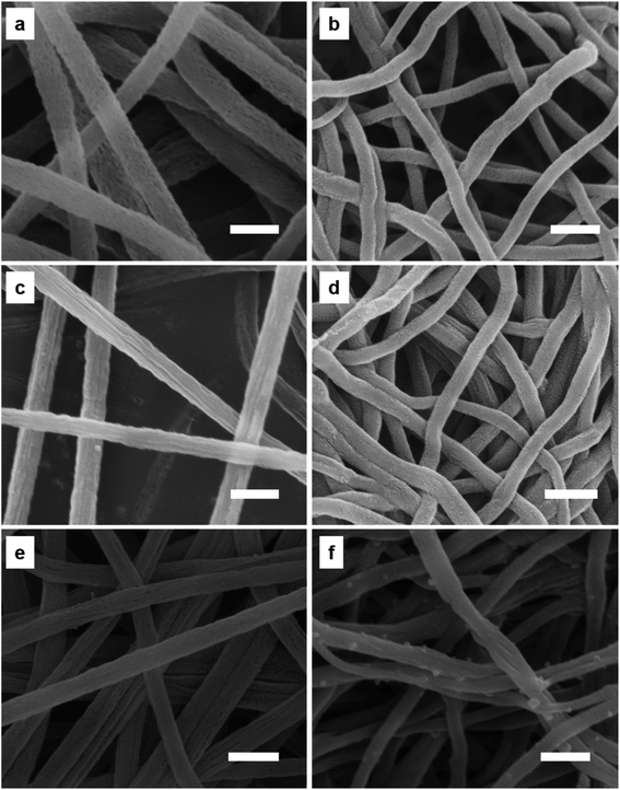 | ||
| Fig. 4 SEM images of (a) porous PAN, (b) PCNFs, (c) porous PAN/PFSA, (d) 0.1F–PCNFs, (e) 0.1Li–porous PAN/PFSA, and (f) 0.1Li–F PCNFs composites. The scale bar is 500 nm. | ||
When deposited on the F–PCNFs, Li NPs are relatively homogeneously dispersed (Fig. 4f, S10 and S12†) on the surface of PCNFs with the diameter ranging from 160 to 270 nm (Fig. 4e). Such a greatly improved homogeneous distribution of Li NPs might result from the rough surface of F–PCNFs and ion bonding between sulfonate and alkali metal ions, which can provide more nucleation sites for the formation and also prevent the agglomeration of Li NPs, and result in an improvement in the hydrogen storage performance. Furthermore, HRTEM images (Fig. S13a and b†) show that nanopores are uniformly dispersed on the surface of PCNFs and also display that the Li–F–PCNFs composites have a diameter of about 200 nm, and energy dispersive spectroscopy (EDS) spectrum (Fig. S13c†) also indicates the presence of C, O, N, F and S elements, which is consistent with the above SEM results. Generally, the EDS of HRTEM cannot be useful for lithium. There is no lithium element in the EDS of 0.1Li–F–PCNFs.
The nitrogen adsorption–desorption isotherm and the corresponding Barrett–Joyner–Halenda (BJH) pore size distribution curve of the obtained 0.1Li–F–PCNFs composites were measured. The specific surface area of 0.1Li–F–PCNFs composites is 34.3 m2 g−1. Obvious adsorption steps from 0.1Li–F–PCNFs composites can be found in the relative pressure range of 0.4–1.0 MPa. Moreover, the pore sizes analyzed by the BJH method show that the primary mesopore size is 2.65 nm for the 0.1Li–F–PCNFs composites (Fig. S14†). These can be ascribed to the capillary condensation of nitrogen molecules in mesopores with relatively uniform dimensions,56 indicating the end of the capillary condensation and narrow pore size distribution, which has a beneficial effect on increasing hydrogen absorption.
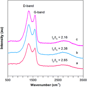
Raman spectroscopy is a useful tool for the characterization of the carbon structure of porous CNFs based materials. As depicted in Fig. 5, two strong bands at around 1347 and 1586 cm−1 are observed in 0.01F–PCNFs, 0.05F–PCNFs, 0.1F–PCNFs, 0.01Li–F–PCNFs, 0.05Li–F–PCNFs and 0.1Li–F–PCNFs composites, which correspond to the disordered (D band, defects) and graphitic carbons (G band for sp2 domains), respectively. It is noted that the area ratio of the D band to the G band (ID/IG) for 0.1Li–F–PCNFs is 2.16, which is much lower than those of 0.01F–PCNFs (3.04), 0.05F–PCNFs (2.56), 0.1F–PCNFs (2.26), 0.01Li–F–PCNFs (2.65) and 0.05Li–F–PCNFs (2.38) (Fig. 5b and c and S15†). These results indicate the greatly enhanced graphitic structure of the former, which might be mainly attributed to the graphitization effect of fluorine and lithium dopants. Such an improved graphitic structure can offer an enhanced carbon framework sp2 conjugation of PCNFs surfaces, which is favorable for further hydrogen absorption processes.
In order to obtain more information on the 0.1Li–F–PCNF after the codoping processes, the composite was analyzed by XPS. Fig. 6 shows the XPS survey together with the high resolution XPS spectra of F 1s and Li 1s. Fig. 6a clearly displays intense F 1s and Li 1s peaks, thus verifying the successful codoping of PCNFs with surface components of 82.92% C, 12.56% N, 4.11% O, 0.06% S, and 0.35% F. There is a peak at 284.2 eV of C 1s, indicating pure carbon, and 286.2 eV, related to C–F bond. Meanwhile, the peak at 285.6 eV of C 1s is related to C–N, C–O and C–S bonds, which may be introduced from PVP and lithium hydroxide residuals. Furthermore, it is evident from the F 1s deconvoluted peaks (Fig. 6c) that fluorine is incorporated into the CNFs in two configurations: C–F (685.6 eV) and C–F (687.3 eV) fluorine species,57–59 which indicate that the fluorine element is successfully doped into the PCNFs. Meanwhile, it is evident from the S 2p deconvoluted peaks (Fig. 6d) that sulfur is incorporated into the PCNFs in two configurations: the thiophene (S–C–S) (162.5 eV), and oxidized (SOx–C) (163.9 eV) sulfur species. This is attributed to a higher positive charge and spin density of carbon atoms, which can provide the more active sites and offer a better hydrogen adsorption density. Notably, the theoretical atom weight content of lithium is calculated as 0.013 wt% (the molar ratio of S![[thin space (1/6-em)]](https://www.rsc.org/images/entities/char_2009.gif) :
:![[thin space (1/6-em)]](https://www.rsc.org/images/entities/char_2009.gif) Li = 1), which is too low to be accurately determined.
Li = 1), which is too low to be accurately determined.
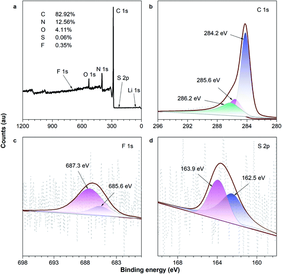 | ||
| Fig. 6 XPS spectra: (a) survey scan; and the (b) C 1s, (c) F 1s and (d) S 2p regions of the 0.1Li–F–PCNFs composites. | ||
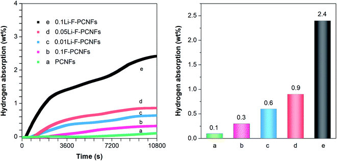
The hydrogen adsorption experiments were carried out under 10 MPa at 0 °C. Typical high-pressure hydrogen adsorption isotherms are shown in Fig. 7. This shows that the hydrogen concentration gradually increases as the adsorption time increases. The adsorption performance of PCNFs and 0.1F–PCNFs composites is almost complete within 10![[thin space (1/6-em)]](https://www.rsc.org/images/entities/char_2009.gif) 800 s, with storage capacities of 0.1 and 0.3 wt%, respectively. This illustrates that F–PCNFs can enhance the hydrogen adsorption, compared to PCNFs composites. In order to further increase the hydrogen storage capacity, alkali metal lithium was introduced into the F–PCNFs. Moreover, those sulfonate ions from PFSA can be exchanged with lithium hydroxide to anchor the lithium ions, so that they are fixed during the carbonization process of porous PAN/PFSA–Li, thereby obtaining lithium particles dispersed uniformly on the surface of F–PCNFs. As shown in Fig. 7c–e, the hydrogen storage capacities of 0.01Li–F–PCNFs, 0.05Li–F–PCNFs and 0.1Li–F–PCNFs are about 0.6, 0.9 and 2.4 wt%, respectively, under the above measurement conditions, which are enhanced with the increasing contents of fluorine and lithium dopants. This is attributed to the high electron affinity of the sp2 carbon framework resulting from fluorine and lithium dopants, providing strong stabilization among Li–F–PCNFs and the molecular H2. More importantly, lithium dopants act as positive (acidic) cores that attract hydrogen molecules. The above-mentioned results suggest that fluorine and lithium dopants in PCNFs endow these composites with an excellent hydrogen storage performance, which could reach the DOE goals in the future.
800 s, with storage capacities of 0.1 and 0.3 wt%, respectively. This illustrates that F–PCNFs can enhance the hydrogen adsorption, compared to PCNFs composites. In order to further increase the hydrogen storage capacity, alkali metal lithium was introduced into the F–PCNFs. Moreover, those sulfonate ions from PFSA can be exchanged with lithium hydroxide to anchor the lithium ions, so that they are fixed during the carbonization process of porous PAN/PFSA–Li, thereby obtaining lithium particles dispersed uniformly on the surface of F–PCNFs. As shown in Fig. 7c–e, the hydrogen storage capacities of 0.01Li–F–PCNFs, 0.05Li–F–PCNFs and 0.1Li–F–PCNFs are about 0.6, 0.9 and 2.4 wt%, respectively, under the above measurement conditions, which are enhanced with the increasing contents of fluorine and lithium dopants. This is attributed to the high electron affinity of the sp2 carbon framework resulting from fluorine and lithium dopants, providing strong stabilization among Li–F–PCNFs and the molecular H2. More importantly, lithium dopants act as positive (acidic) cores that attract hydrogen molecules. The above-mentioned results suggest that fluorine and lithium dopants in PCNFs endow these composites with an excellent hydrogen storage performance, which could reach the DOE goals in the future.
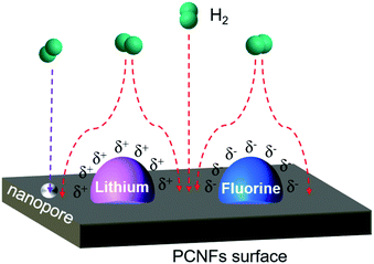
The mechanism of hydrogen storage from Li–F–PCNFs is shown in Fig. 8. When the hydrogen molecule moves from outside the surface of PCNFs, the hydrogen molecule is affected by the electronegativity gap between the lithium and fluorine. Fluorine has the highest electronegativity (4.0) among the elements and lithium has the lowest electronegativity (0.98). The electronegativity of carbon lies between that of fluorine and lithium at 2.55. Therefore, fluorine exhibits electrically negative-charged characteristics (δ−) on the surface, and the lithium exhibits relatively positively charged characteristics (δ+). Consequently, this electronegativity difference will electrically attract the hydrogen molecule into PCNFs.60 The electrons from the hydrogen molecule are attracted towards the surface by electric force and can be adsorbed on the surface of the PCNFs more efficiently. Furthermore, the nanopore size of the PCNFs is 2.65 nm for the Li–F–PCNFs composites, which can be ascribed to the capillary condensation according to the equilibrium temperature of adsorption and the geometrical characteristics of the adsorbent. Therefore, these effects are beneficial to an improvement of hydrogen storage.
Conclusions
In summary, we report a facile synthesis procedure for the preparation of Li–F–PCNFs composites with noticeable performance as hydrogen storage materials. The Li–F–PCNFs were synthesized through a simple electrospinning, hydrothermal treatment, and carbonization process. Especially, PFSA was not only a fluorine source to enhance the hydrogen adsorption density, but it also acted to prevent the agglomeration of lithium nanoparticles through an ion-exchange method. The porous carbon framework endows the Li NPs with a uniform distribution, effective space confinement, and a much higher specific surface area. The unique architecture of the Li–F–PCNFs composites allows 2.4 wt% absorption under 10 MPa at 0 °C. Therefore, this strategy represents a highly novel approach for synthesizing Li–F–PCNF scomposites to act as hydrogen storage materials that exhibit superior storage properties. It is also expected that these materials can be significant potential materials in the electrochemical and fuel-cell fields.Author contributions
This work was finished through contributions from all authors. The design and synthesis of Li–F–PCNFs used in this work, and most of tests relating to the structure and morphology, were contributed to by Xiaohong Chen, Zhiyong Xue, Kai Niu, and Xundao Liu. With the help of Wei Lv, Bao Zhang, Zhongyu Li, Hong Zeng, and Yu Ren, the hydrogen storage experiments were successfully completed. Prof. Ying Wu and Prof. Yongming Zhang directed the whole process relating to this carbon-based storage system and revised the manuscript. All authors have given approval to the final version of this manuscript.Conflicts of interest
All authors declare that there are no conflicts of interest.Acknowledgements
This work was financially supported by the Postdoctoral Innovative Talent Support Program of China (Grant No. BX20190112), the National Natural Science Foundation of China (Grant No. 52071141, 51971092, 51771056 and 51701043), National Key Research and Development Plan (Grant No. 2018YFB1502102), and Equipment Pre-research Field Foundation (6140721040111).References
- L. Firlej, P. Pfeifer and B. Kuchta, Understanding universal adsorption limits for hydrogen storage in nano porous systems, Adv. Mater., 2013, 25, 5971–5974 CrossRef CAS
.
- H. Nishihara and T. Kyotani, Templated nanocarbons for energy storage, Adv. Mater., 2012, 24, 4473–4498 CrossRef CAS
.
- S. Z. Mortazavi, P. Parvin, A. Reyhani, R. Malekfarc, S. Mirershadid, M. Mohan, V. K. Sharma, E. A. Kumar and V. Gayathri, Hydrogen storage property of laser induced Pd-nanoparticle decorated multi-walled carbon nanotubes, RSC Adv., 2013, 3, 1397–1409 RSC
.
- G. Xia, D. Li, X. Chen, Y. Tan, Z. Tang, Z. Guo, H. Liu, Z. Liu and X. Yu, Carbon-coated Li3N nanofibers for advanced hydrogen storage, Adv. Mater., 2013, 25, 6238–6244 CrossRef CAS
.
- A. Schneemann, J. L. White, S. Kang, S. Jeong, L. F. Wan, E. S. Cho, T. W. Heo, D. Prendergast, J. J. Urban, B. C. Wood, M. D. Allendorf and V. Stavila, Nanostructured metal hydrides for hydrogen storage, Chem. Rev., 2018, 118, 10775–10839 CrossRef CAS
.
- J. Xue, T. Wu, Y. Dai and Y. Xia, Electrospinning and electrospun nanofibers: methods, materials, and applications, Chem. Rev., 2019, 119, 5298–5415 CrossRef CAS
.
- R. W. P. Wagemans, J. H. van Lenthe, P. E. de Jongh, A. J. Dillen and K. P. de Jong, Hydrogen storage in magnesium clusters: quantum chemical study, J. Am. Chem. Soc., 2005, 127, 16675–16680 CrossRef CAS
.
- Y. Zhang, H. Zhang, X. Ding, D. Liu, Q. Zhang and T. Si, Microstructure characterization and hydrogen storage properties study of Mg2Ni0.92M0.08 (M = Ti, V, Fe or Si) alloys, Prog. Nat. Sci.: Mater. Int., 2018, 28, 464–469 CrossRef CAS
.
- S. Y. Kang, T. W. Heo, M. D. Allendorf and B. C. Wood, Morphology–dependent stability of complex metal hydrides and their intermediates using first-principles calculations, ChemPhysChem, 2019, 20, 1340–1347 CrossRef CAS
.
- W. Yuan, M. Ge, K. Wang, X. Hou, N. Liu, Z. Deng, R. Guo, S. Liu, Y. Zhao, J. He, W. Xi, J. Luo and Y. Ding, Atomic-scale selectivity of hydrogen for storage sites in Pd nanoparticles at atmospheric pressure, Nanoscale, 2019, 11, 10198–10202 RSC
.
- J. Chen, S.-L. Li, Z.-L. Tao, Y.-T. Shen and C.-X. Cui, Titanium disulfide nanotubes as hydrogen-storage materials, J. Am. Chem. Soc., 2003, 125, 5284–5285 CrossRef CAS
.
- Q. Ma, Y. Yu, M. Sindoro, A. G. Fane, R. Wang and H. Zhang, Carbon-based functional materials derived from waste for water remediation and energy storage, Adv. Mater., 2017, 29, 1605361 CrossRef
.
- C. L. Carr, W. Jayawardana, H. Zou, J. L. White, F. E. Gabaly, M. S. Conradi, V. Stavila, M. D. Allendorf and E. H. Majzoub, Anomalous H2 desorption rate of NaAlH4 confined in nitrogen-doped nanoporous carbon frameworks, Chem. Mater., 2018, 30, 2930–2938 CrossRef CAS
.
- B. Zhang, J. Yuan and Y. Wu, Catalytic effects of Mg(BH4)2 on the desorption properties of 2LiNH2–MgH2 mixture, Int. J. Hydrogen Energy, 2019, 44, 19294–19301 CrossRef CAS
.
- B. Zhang and Y. Wu, Recent advances in improving performances of the lightweight complex hydrides Li–Mg–NH system, Prog. Nat. Sci.: Mater. Int., 2017, 27, 21–23 CrossRef CAS
.
- S. J. Yang, J. H. Cho, K. S. Nahm and C. R. Park, Enhanced hydrogen storage capacity of Pt-loaded CNT@MOF-5 hybrid composites, Int. J. Hydrogen Energy, 2010, 35, 13062–13067 CrossRef CAS
.
- T. Hussain, B. Mortazavi, H. Bae, T. Rabczukb, H. Lee and A. Karton, Enhancement in hydrogen storage capacities of light metal functionalized borone graphdiyne nanosheets, Carbon, 2019, 147, 199–205 CrossRef CAS
.
- B. C Bai, G. J. Kim, M. Naik and Y.-S. Lee, The hydrogen storage capacity of metal-containing polyacrylonitrile-based electrospun carbon nanofibers, Carbon Lett., 2011, 12, 171–176 CrossRef
.
- H. Cheng, G. P. Pez and A. C. Cooper, Mechanism of hydrogen sorption in single-walled carbon nanotubes, J. Am. Chem. Soc., 2001, 123, 5845–5846 CrossRef CAS
.
- A. Zuttel, P. Sudan, P. Mauron, T. Kiyobayashi, C. Emmenegger and L. Schlapbach, Hydrogen storage in carbon nanostructures, Int. J. Hydrogen Energy, 2002, 27, 203–212 CrossRef CAS
.
- X. Chen, M. Chi, L. Xing, X. Xie, S. Liu, Y. Liang, M. Zheng, H. Hu, H. Dong, Y. Liu, S. P. Jiang and Y. Xiao, Natural plant template-derived cellular framework porous carbon as a high-rate and long-life electrode material for energy storage, ACS Sustainable Chem. Eng., 2019, 7, 5845–5855 CrossRef CAS
.
- V. B. Parambhath, R. Nagar and S. Ramaprabhu, Effect of nitrogen doping on hydrogen storage capacity of palladium decorated graphene, Langmuir, 2012, 28, 7826–7833 CrossRef CAS
.
- H. Zhou, X. Liu, J. Zhang, X. Yan, Y. Liu and A. Yuan, Enhanced room-temperature hydrogen storage capacity in Pt-loaded graphene oxide/HKUST-1 composites, Int. J. Hydrogen Energy, 2014, 39, 2160–2167 CrossRef CAS
.
- P. Chen, X. Wu, J. Lin and K. L. Tan, High H2 uptake by alkali-doped carbon nanotubes under ambient pressure and moderate temperatures, Science, 1999, 285, 91–93 CrossRef CAS
.
- Y. Y. Fan, B. Liao, M. Liu, Y. L. Wei, M. Q. Lu and H. M. Cheng, Tailoring the diameters of vapor-grown carbon nanofibers, Carbon, 1999, 37, 1649–1652 CrossRef CAS
.
- J. M. Skowroński, P. Scharff, N. Pfänder and S. Cui, Room temperature electrochemical opening of carbon nanotubes followed by hydrogen storage, Adv. Mater., 2003, 15, 55–57 CrossRef
.
- Y. Woo, B.-S. Kim, J.-W. Lee, J. Park, M. Cha, S. Takeya, J. Im, Y. Lee, T.-I. Jeon, H. Bae, H. Lee, S. S. Han, B. C. Yeo, D. Kim and J. Yoon, Enhanced hydrogen-storage capacity and structural stability of an organic clathrate structure with fullerene (C60) guests and lithium doping, Chem. Mater., 2018, 30, 3028–3039 CrossRef CAS
.
- C. L. Carr, W. Jayawardana, H. Zou, J. L. White, F. E. Gabaly, M. S. Conradi, V. Stavila, M. D. Allendorf and E. H. Majzoub, Anomalous H2 desorption rate of NaAlH4 confined in nitrogen-doped nanoporous carbon frameworks, Chem. Mater., 2018, 30, 2930–2938 CrossRef CAS
.
- L. Wang and R. T. Yang, Hydrogen storage properties of N-doped microporous carbon, J. Phys. Chem. C, 2009, 113, 21883–21888 CrossRef CAS
.
- K. Lan, L. Gong, M. Yang, X. Huang, P. Jiang, K. Wang, L. Ma and R. Li, Nitrogen and phosphorus dual-doping carbon shells encapsulating ultrafine Mo2C particles as electrocatalyst for hydrogen evolution, J. Colloid Interface Sci., 2019, 553, 148–155 CrossRef CAS
.
- B. Li, J. Li, H. Zhao, X. Yu and H. Shao, Mg-based metastable nano alloys for hydrogen storage, Int. J. Hydrogen Energy, 2019, 44, 6007–6018 CrossRef CAS
.
- B. Liu, B. Zhang, Y. Wu, W. Lv and S. Zhou, Theoretical prediction and experimental study on catalytic mechanism of incorporated Ni for hydrogen absorption of Mg, Int. J. Hydrogen Energy, 2019, 44, 27885–27895 CrossRef CAS
.
- L. Chong, X. Zeng, W. Ding, D.-J. Liu and J. Zou, NaBH4 in “graphene wrapper:” significantly enhanced hydrogen storage capacity and regenerability through nanoencapsulation, Adv. Mater., 2015, 27, 5070–5074 CrossRef CAS
.
- N. Balahmar and R. Mokaya, Pre-mixed precursors for modulating the porosity of carbons for enhanced hydrogen storage: towards predicting the activation behaviour of carbonaceous matter, J. Mater. Chem. A, 2019, 7, 17466–17479 RSC
.
- C. P. Bald, B. P. C. Hereijgers, J. H. Bitter and K. P. de Jong, Facilitated hydrogen storage in NaAlH4 supported on carbon nanofibers, Angew. Chem., Int. Ed., 2006, 45, 3501–3503 CrossRef
.
- E. Tylianakis, G. M. Psofogiannakis and G. E. Froudakis, Li-doped pillared graphene oxide: a graphene-based nanostructured material for hydrogen storage, J. Phys. Chem. Lett., 2010, 1, 2459–2464 CrossRef CAS
.
- H. Lee, J. Ihm, M. L. Cohen and S. G. Louie, Calcium-decorated graphene-based nanostructures for hydrogen storage, Nano Lett., 2010, 10, 793–798 CrossRef CAS
.
- R. T. Yang, Hydrogen storage by alkali-doped carbon nanotubes – revisited, Carbon, 2000, 38, 623–641 CrossRef CAS
.
- Y. Li, Y. Xiao, H. Dong, M. Zheng and Y. Liu, Polyacrylonitrile-based highly porous carbon materials for exceptional hydrogen storage, Int. J. Hydrogen Energy, 2019, 44, 23210–23215 CrossRef CAS
.
- Z. Kou, W. Zang, W. Pei, L. Zheng, S. Zhou, S. Zhang, L. Zhang and J. Wang, Sacrificial Zn strategy enables anchoring of metal single atoms on the exposed surface of holey 2D molybdenum carbide nanosheets for efficient electrocatalysis, J. Mater. Chem. A, 2020, 8, 3071–3082 RSC
.
- Y. Ma, T. Yang, H. Zou, We. Zang, Z. Kou, L. Mao, Y. Feng, L. Shen, S. J. Pennycook, L. Duan, X. Li and J. Wang, Synergizing Mo single atoms and Mo2C nanoparticles on CNTs synchronizes selectivity and activity of electrocatalytic N2 reduction to ammonia, Adv. Mater., 2020, 2002177 CrossRef CAS
.
- Z. Kou, W. Zang, Y. Ma, Z. Pan, S. Mu, X. Gao, B. Tang, M. Xiong, X. Zhao, A. K. Cheetham, L. Zheng and J. Wang, Cage-confinement pyrolysis route to size-controlled molybdenum-based oxygen electrode catalysts: from isolated atoms to clusters and nanoparticles, Nano Energy, 2020, 67, 104288 CrossRef CAS
.
- G. Nie, X. Zhao, Y. Luan, J. Jiang, Z. Kou and J. Wang, Key issues facing electrospun carbon nanofibers in energy applications: ongoing approaches and challenges, Nanoscale, 2020, 12, 13225–13248 RSC
.
- Y. Dzenis, Spinning continuous fibers for nanotechnology, Science, 2004, 304, 1917–1919 CrossRef CAS
.
- J.-M. Li, Realizing single-crystalline vertically-oriented and high-density electrospun nanofibril bundles by controlled postcalcination, CrystEngComm, 2017, 19, 3392–3397 RSC
.
- J.-M. Li, D.-P. Wei, Y.-B. Hu, J. Fang and Z.-A. Xu, Synthesis of ultrafine green-emitting BaCO3 nanowires with 18.5 nm-diameter by CO2 vapor-assisted electrospinning, CrystEngComm, 2014, 16, 964–968 RSC
.
- H. Cheng, X. Sha, L. Chen, A. C. Cooper, M.-L. Foo, G. C. Lau, W. H. Bailey III and G. P. Pez, An enhanced hydrogen adsorption enthalpy for fluoride intercalated graphite compounds, J. Am. Chem. Soc., 2009, 131, 17732–17733 CrossRef CAS
.
- B. Nyulasi and A. Kovacs, Theoretical study of F–(H2)n and Cl–(H2)n (n = 1–8) anion complexes, Chem. Phys. Lett., 2006, 426, 26–29 CrossRef CAS
.
- A. Trewin, G. R. Darling and A. I. Cooper, “Naked” fluoride binding sites for physisorptive hydrogen storage, New J. Chem., 2008, 32, 17–20 RSC
.
- X. Liu, D. Wu, X. Liu, X. Luo, Y. Liu, Q. Zhao, J. Li and D. Dong, Perfluorinated comb-shaped cationic polymer containing long-range ordered main chain for anion exchange membrane, Electrochim. Acta, 2020, 336, 135757 CrossRef CAS
.
- F. E. Pinkerton, B. G. Wicke, C. H. Olk, G. G. Tibbetts, G. P. Meisner, M. S. Meyer and J. F. Herbst, Thermogravimetric measurement of hydrogen absorption in alkali-modified carbon materials, J. Phys. Chem. B, 2000, 104, 9460–9467 CrossRef CAS
.
- S. Pei, Z. Zhou, X. Chen, X. Huang, T. Liu, B. Cao and F. Wang, Co/CoO nanoparticles/Ag nanowires/nitrogen codoped electrospun carbon nanofibers as efficient electrocatalysts for oxygen reduction, Int. J. Electrochem. Sci., 2016, 11, 8994–9006 CrossRef CAS
.
- X. Liu, X. Luo, X. Chen, S. Zou, X. Liu, J. Li, H. Li and D. Dong, Perfluorinated membrane electrode assembly containing metal-free-catalyst cathode for anion exchange membrane fuel cells, J. Electroanal. Chem., 2020, 871, 114283 CrossRef CAS
.
- M. Falk, An infrared study of water in perfluorosulfonate (Nafion) membranes, Can. J. Chem., 1980, 58, 1495–1501 CrossRef CAS
.
- Z. Cai, Y. Liu, S. Liu, L. Li and Y. Zhang, High performance of lithium-ion polymer battery based on nonaqueous lithiated perfluorinated sulfonic ion-exchange membranes, Energy Environ. Sci., 2012, 5, 5690–5693 RSC
.
- K. Xia, Q. Gao, C. Wu, S. Song and M. Ruan, Activation, characterization and hydrogen storage properties of the mesoporous carbon CMK-3, Carbon, 2007, 45, 1989–1996 CrossRef CAS
.
- F. L. Normand, J. Hommer, T. Szörényi, C. Fuchs and E. Fogarassy, XPS study of pulsed laser deposited CNx films, Phys. Rev. B: Condens. Matter Mater. Phys., 2001, 64, 235416 CrossRef
.
- A. Tressaud, F. Moguet, S. Flandrois, M. Chambon, C. Guimon, G. Nanse, E. Papirer, V. Gupta and O. P. Bahl, On the nature of C–F bonds in various fluorinated carbon materials: XPS and TEM investigations, J. Phys. Chem. Solids, 1996, 57, 745–751 CrossRef CAS
.
- I. Palchan, M. Crespin, H. Estarde-szwarckope and B. Rousseau, Graphite fluorides: an XPS study of a new type of C–F bonding, Chem. Phys. Lett., 1989, 157, 321–327 CrossRef CAS
.
- J. S. Im, S.-J. Park and Y.-S. Lee, The metal–carbon–fluorine system for improving hydrogen storage by using metal and fluorine with different levels of electronegativity, Int. J. Hydrogen Energy, 2009, 34, 1423–1428 CrossRef CAS
.
Footnote |
| † Electronic supplementary information (ESI) available. See DOI: 10.1039/d0ra06500e |
| This journal is © The Royal Society of Chemistry 2021 |

