
 Open Access Article
 This Open Access Article is licensed under a
 Creative Commons Attribution 3.0 Unported Licence
Multifunctional superparamagnetic nanoparticles with a fluorescent silica shell for the in vitro study of bio-nano interactions at the subcellular scale†
Lorenzo
Cursi‡
 a,
Silvia
Vercellino‡
ab,
Mura M.
McCafferty
a,
Emily
Sheridan
a,
Vanya
Petseva
a,
Laurent
Adumeau
*a and
Kenneth A.
Dawson
*a
a,
Silvia
Vercellino‡
ab,
Mura M.
McCafferty
a,
Emily
Sheridan
a,
Vanya
Petseva
a,
Laurent
Adumeau
*a and
Kenneth A.
Dawson
*a
aCentre for BioNano Interactions, School of Chemistry, University College Dublin, Belfield, Dublin 4, Ireland. E-mail: laurent.adumeau@cbni.ucd.ie; Kenneth.a.dawson@cbni.ucd.ie
bUCD Conway Institute of Biomolecular and Biomedical Research, School of Biomolecular and Biomedical Science, University College Dublin, Belfield, Dublin 4, Ireland
First published on 27th September 2021
Abstract
Despite the high level of interest in bio-nano interactions, detailed intracellular mechanisms that govern nanoscale recognition and signalling still need to be unravelled. Magnetic nanoparticles (NPs) are valuable tools for elucidating complex intracellular bio-nano interactions. Using magnetic NPs, it is possible to isolate cell compartments that the particles interact with during intracellular trafficking. Studies at the subcellular scale rely heavily on optical microscopy; therefore, combining the advantages of magnetic recovery with excellent imaging properties to allow intracellular NP tracking is of utmost interest for the nanoscience field. However, it is a challenge to prepare highly magnetic NPs with a suitable fluorescence for the fluorescence imaging techniques typically used for biological studies. Here we present the synthesis of biocompatible multifunctional superparamagnetic multicore NPs with a bright fluorescent silica shell. The incorporation of an organic fluorophore in the silica surrounding the magnetic multicore was optimised to enable the particles to be tracked with the most common imaging techniques. To prevent dye loss resulting from silica dissolution in biological environments, which would reduce the time that the particles could be tracked, we added a thin dense encapsulating silica layer to the NPs which is highly stable in biological media. The synthesised multifunctional nanoparticles were evaluated in cell uptake experiments in which their intracellular location could be clearly identified using fluorescence imaging microscopy, even after 3 days. The magnetic properties of the iron oxide core enabled both efficient recovery of the NPs from the intracellular environment and the extraction of cell compartments involved in their intracellular trafficking. Thus, the NPs reported here provide a promising tool for the study of the processes regulating bio-nano interactions.
Introduction
There is a growing focus on determining the detailed inter- and intracellular mechanisms that govern nanoscale recognition and signalling.1,2 Understanding these fundamental processes would enable further advancements in nanomedicine. However, to progress in this field, the scientific community needs to develop new tools and methodologies. In recent decades, superparamagnetic nanoparticles (NPs) have found applications in heterogeneous catalysis,3 enzyme immobilization,4,5 targeted drug delivery,6,7 MRI enhancement,6,7 hyperthermia treatment,8–11 and point of care devices,12 owing to their unique magnetic properties. In biology, magnetic separation is often used in purification,13 in which the object of interest is labelled with a magnetic particle and manipulated by the application of a magnetic field.2 Recently, a number of studies have exploited magnetic particles for the isolation of cells,14 viruses,15,16 organelles,13 exosomes17,18 and other cell compartments.2,13 This ability to selectively recover superparamagnetic NPs from biological environments means they are becoming an essential tool for unravelling the interactions between nanoparticles and cells.2,13Because they allow the same nanoparticle to be used throughout the experimental workflow enabling the direct correlation of the information collected during each stage, multifunctional nanoparticles19–21 are an important development in resolving the complexity of these bio-nano interactions. Fluorescent NPs are widely used to study bio-nano interactions as they offer multiple advantages for tracking NP behaviour in the intracellular environment and offer an alternative to other destructive techniques. For example, optical imaging is often used to observe the intracellular trafficking of nanomaterials,22,23 while fluorescence measurement in flow cytometry can be used to quantify cellular uptake and other aspects of cell response.24 As such, combining magnetic properties with fluorescence within a single nanoparticle would provide a valuable tool for the study of bio-nano interactions as it allows one to directly correlate what is observed by microscopy with the molecular analysis of the cellular compartments magnetically extracted with the NPs. We next consider how to design such a tool.
For applications involving magnetic extraction, structures with a core made of several superparamagnetic NPs coated by a polymer have proven to outperform single small superparamagnetic NPs.25 By forming such multicore structures, the superparamagnetic properties of the single NPs are retained by the whole nanoconstruct.26 Multicores can be extracted more efficiently as they are less susceptible to Brownian motion and their magnetic force corresponds to the sum of the forces experienced by the single superparamagnetic particles. Iron oxide superparamagnetic NPs (SPIONs) are particularly interesting due to their simple synthesis, ease of functionalization and high magnetic susceptibility.27
There are several challenges to consider when designing NPs to obtain robust and reliable results based on fluorescence in biological studies. The NP signal must be clearly distinguishable from cellular autofluorescence to avoid phototoxicity from exposure to high laser intensity, common in the case of low NP fluorescence emission. Dye leakage should be eliminated as far as possible as this can lead to a diffuse signal that decreases over time and affects cell viability; poor photostability should be avoided as this precludes live cell imaging due to photobleaching. Although these challenges are now considered trivial for some transparent materials such as silica or polystyrene, they are not as easily overcome when the nanoparticle incorporates strongly absorbing materials such as metals or metal oxides.
Covalent incorporation of fluorescent organic molecules into silica NPs is easily accomplished through the modification of silicate derivatives.28,29 Moreover, silica is widely used in the fabrication of NPs and in the growth of shells on NPs because its synthesis allows both fine control over size and versatile surface modifications. It is also considered to be biocompatible and can help to reduce the toxicity of some metallic NPs.30
Magnetic NPs coated with silica have been previously reported; however, these studies have predominantly involved small, single magnetic core NPs,31 or NPs with few cores incorporated within a thick silica matrix,32,33 making it difficult to magnetically extract them with the required efficiency for biological applications. To the best of our knowledge, there are few reports of synthesis of magnetic multicores loaded with a large number of SPIONs that are also highly fluorescent. Chen et al. report the synthesis of magneto-fluorescent nanoparticles combining the prospect of magnetic manipulation/extraction of the nanoparticles, owing to the magnetic multicore, with bright fluorescence provided by the co-assembled quantum dots.34 However, quantum dots are known to be toxic and their synthesis complex. We were interested in using conventional organic fluorescent dyes instead of quantum dots but obtaining bright nanoparticles while also limiting fluorescence loss over time poses challenges. It is particularly important to load sufficient dye to ensure the particles are bright enough for the desired applications. On the other hand, overloading the silica matrix with organic dyes can cause quenching, mainly due to Förster resonance energy transfer (FRET) effects35,36 caused by the typically small Stokes shift of the organic fluorophores, but also due to agglomeration-caused quenching (ACQ) and proximity-caused quenching (PCQ).37
Dye leakage, an often neglected issue, can occur due to the dissolution of amorphous silica coatings in aqueous solutions and represents a serious limitation, especially in biological applications where the combination of a slightly alkaline pH and a relatively high salt concentration of the biological media has been shown to accelerate this process.38 To prevent dye loss, NPs can be coated with a protective, denser silica layer. Such a layer is usually synthesised with the aid of amino acids, such as arginine, that catalyse the synthesis of a denser layer of silica.39 However, amino acids can also adsorb on the surface of the NPs, altering their surface properties and subsequently interfering with their intracellular trafficking.
Here we present the design of a multifunctional core–shell nanoconstruct composed of a cluster of SPIONs, encapsulated in a fluorescent amorphous silica layer and protected with a thin layer of denser silica to prevent leakage of the fluorophore in biological media. The loading of fluorescein, an inexpensive organic dye, has been optimised to deliver maximum brightness of the core–shell structure. We also propose a mechanism of formation and a mechanism of action for the protective layer. We demonstrate that these nanoparticles can be tracked inside cells using classical and high-resolution fluorescence microscopy, and that the nanoparticles can be magnetically isolated after their journey within the cells. As such, we provide a tool with great potential for the study of bio-nano interactions at the subcellular level.
Results and discussion
Dye loading in the silica matrix
The synthesis of the magnetic multicore for encapsulation in the thin silica shell was adapted from a previously published procedure.40 Multicores composed of magnetite (Fe3O4) NPs were compared to multicores composed of maghemite (γ-Fe2O3) NPs. Both multicores were estimated to be around 50–60 nm in diameter by TEM imaging (see ESI Fig. S1 and S2† for characterisation).Silica is particularly well adapted for fluorescence labelling because it is transparent in the visible light domain. However, the presence of non-transparent cores, as in the case of iron oxide NPs presenting strong absorbance in the visible region of light, impacts the brightness of the particles. Therefore, when designing such core–shell structures, the optimization of dye loading to simultaneously maximize the NPs fluorescence and minimize quenching effects is particularly important.
Organic dyes can be incorporated into the silica matrix by two different processes: physical entrapment in the matrix or covalent conjugation to the matrix.30 The latter is preferred as it reduces dye leaking. It generally requires the dye to be conjugated to a functional organosilane (Fig. 1a) which is then covalently bound to the silica matrix.29,41 Many different commercially available functional organic dyes can be incorporated into the silica matrix depending on the desired application and the available excitation and emission channels of the instrument in question.
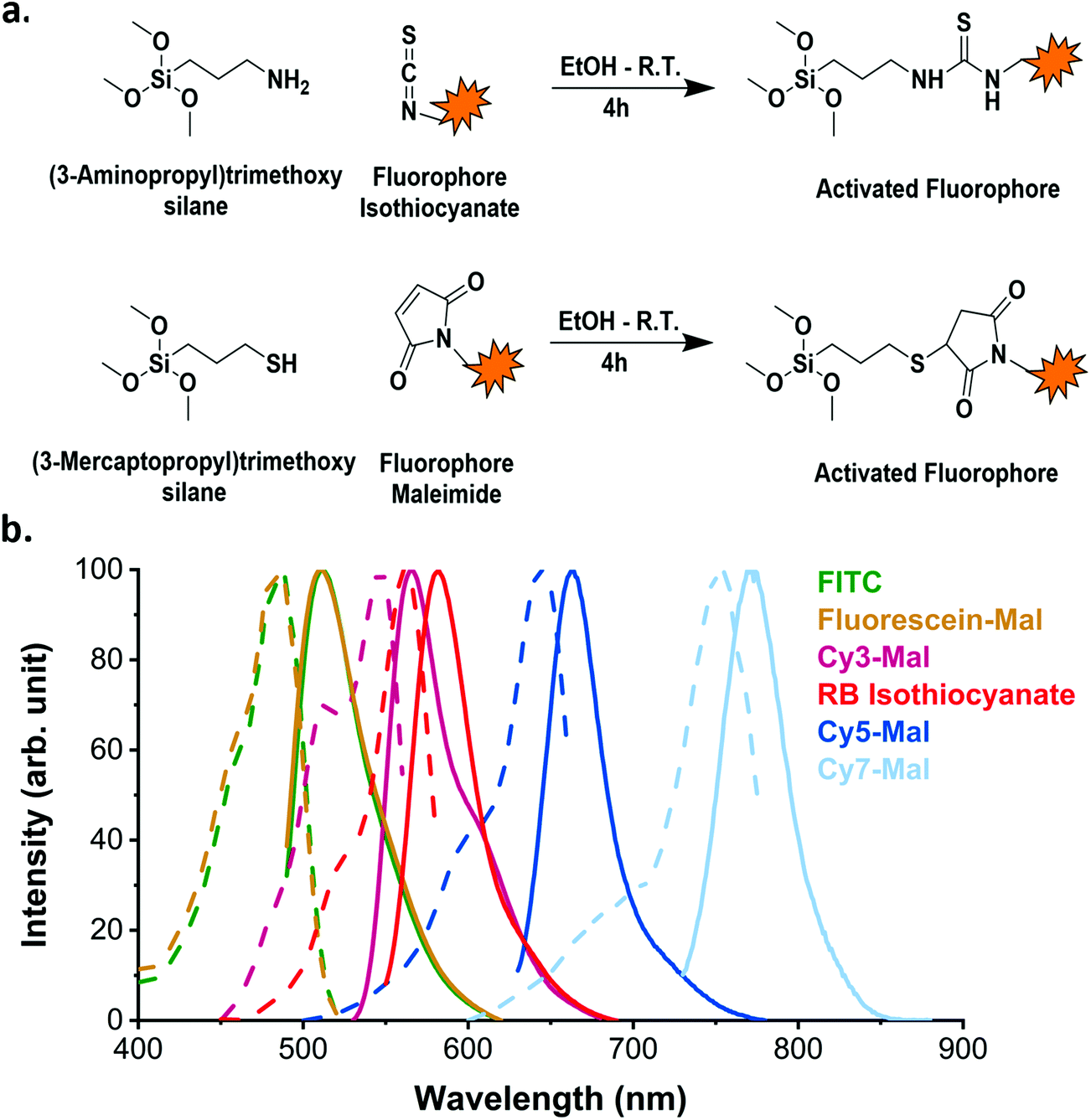 | ||
| Fig. 1 Incorporation of organic dyes into SiO2 NPs. (a) Scheme of reaction between the organic dye (with thiocyanate or maleimide functions) and the respective amino- or mercaptosilane. The product of these reactions then reacts with TEOS under Stöber conditions. (b) The excitation (dotted line) and emission (solid line) spectra of SiO2 NPs doped with different organic fluorophores. The spectra of the incorporated dyes are similar to the spectra of their free forms (as reported by suppliers). | ||
In this study, to illustrate the versatility of the process, we used two different conjugation chemistry methods to prepare the dyes for incorporation into the silica matrix and we also varied the fluorophores. The first route involved the use of (3-aminopropyl)trimethoxysilane (APTMS) to activate two different dyes: Rhodamine B isothiocyanate (RB) and fluorescein isothiocyanate (FITC). The other employed (3-mercaptopropyl)trimethoxysilane (MPTMS) to react with the maleimide function in each of Cyanine 3-, Cyanine 5- and Cyanine 7-maleimide (Cy3, Cy5 and Cy7 respectively) and fluorescein maleimide (FM) dyes. The resulting fluorophore-APTMS or fluorophore-MPTMS adducts were then reacted with tetraethyl orthosilicate (TEOS) in a basic hydro-alcoholic media (via the Stöber process) to covalently incorporate them into the silica matrix. The synthesis led to bright SiO2 NPs with a fluorescence emission ranging the whole spectrum of visible light (Fig. 1b). The organic dyes incorporated into the silica matrix with this strategy retain excitation and emission spectra profiles similar to their free forms (as reported by the supplier).
For the optimization of the fluorescence labelling of the silica shell, we decided to use FITC as it is one of the most inexpensive organic dyes frequently used for labelling NPs for biological studies. To optimise the labelling, plain SiO2 NPs of about 60 nm (similar size and size distribution to iron oxide cores, ESI Fig. S3†) were used in place of the magnetic multicore NPs to eliminate any iron oxide core influence on the fluorescence measurements.
The first parameter we optimised was the excess of APTMS to use per FITC in order to maximise the incorporation of the dye in the silica matrix.
FITC was activated, in ethanol, with an excess of APTMS ranging from 1 to 30 equivalents. After the reaction with APTMS, the dye was incorporated into the silica shell grown over the 60 nm plain-SiO2 core. The dye incorporation was evaluated by measuring the absorbance of the NP dispersion in the visible region.
The amount of dye incorporated in the NPs (calculated as described in ESI methods, Fig. S4†) reached a plateau at an APTMS![[thin space (1/6-em)]](https://www.rsc.org/images/entities/char_2009.gif) :FITC ratio of 10:1 (Fig. 2a). However, using a larger excess appears to improve the fluorescence of the NPs (ESI Fig. S5†) by increasing the fluorescence efficiency of the FITC (Fig. 2b). To explain this observation, we suggest that ACQ plays a major role in quenching the fluorescence when insufficient APTMS excess is present to activate the FITC.37 Indeed, it is known that APTMS can spontaneously form oligomers in the presence of water (even trace amounts) as the amine autocatalyzes the hydrolysis of the methoxy groups, as well as the condensation of the formed silanolates. When a molecule of FITC binds to an oligomer to which another molecule of FITC is already bonded too closely, they can undergo ACQ and FRET. Increasing the excess of APTMS, may increase the (average) length of the oligomers formed or promote the formation of a larger number of oligomers. In both cases, there is a smaller probability that two dye molecules find themselves too close to each other in the same chain and so quenching is reduced. Increasing the APTMS:FITC ratio is then beneficial for the fluorescence of the particles; however, the presence of aminosilanes in the silica matrix can affect the hydrolysis rate of the silica. In some cases, the aminosilane will reduce the dissolution rate of the silica thanks to a combination of factors including the inductive donor effect of the alkyl chain reducing the electropositive character of Si centre, and an increase in hydrophobicity.42,43 In other cases, the presence of aminosilane has been reported to increase the dissolution rate of the silica, possibly due to the presence of amine groups catalysing the hydrolysis as well as the decrease of the condensation of the silica network.29,39 For these reason and because the fluorescence increase remains small (increase of 15% at best), we decided to use only an excess of 10 equivalent of APTMS per dye. While not observed here, large excess of APTMS in different conditions have also been associated to the destabilization of the silica growth leading to aggregation39,44
:FITC ratio of 10:1 (Fig. 2a). However, using a larger excess appears to improve the fluorescence of the NPs (ESI Fig. S5†) by increasing the fluorescence efficiency of the FITC (Fig. 2b). To explain this observation, we suggest that ACQ plays a major role in quenching the fluorescence when insufficient APTMS excess is present to activate the FITC.37 Indeed, it is known that APTMS can spontaneously form oligomers in the presence of water (even trace amounts) as the amine autocatalyzes the hydrolysis of the methoxy groups, as well as the condensation of the formed silanolates. When a molecule of FITC binds to an oligomer to which another molecule of FITC is already bonded too closely, they can undergo ACQ and FRET. Increasing the excess of APTMS, may increase the (average) length of the oligomers formed or promote the formation of a larger number of oligomers. In both cases, there is a smaller probability that two dye molecules find themselves too close to each other in the same chain and so quenching is reduced. Increasing the APTMS:FITC ratio is then beneficial for the fluorescence of the particles; however, the presence of aminosilanes in the silica matrix can affect the hydrolysis rate of the silica. In some cases, the aminosilane will reduce the dissolution rate of the silica thanks to a combination of factors including the inductive donor effect of the alkyl chain reducing the electropositive character of Si centre, and an increase in hydrophobicity.42,43 In other cases, the presence of aminosilane has been reported to increase the dissolution rate of the silica, possibly due to the presence of amine groups catalysing the hydrolysis as well as the decrease of the condensation of the silica network.29,39 For these reason and because the fluorescence increase remains small (increase of 15% at best), we decided to use only an excess of 10 equivalent of APTMS per dye. While not observed here, large excess of APTMS in different conditions have also been associated to the destabilization of the silica growth leading to aggregation39,44
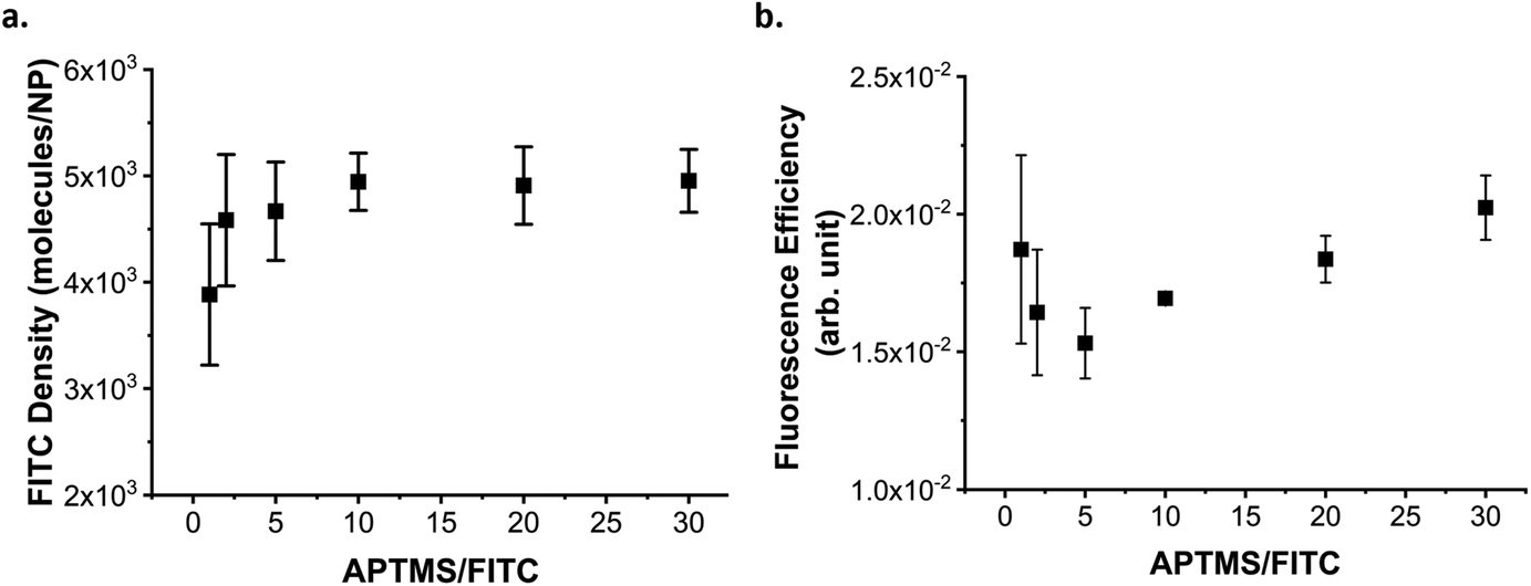 | ||
| Fig. 2 Optimization of FITC activation with APTMS. (a) Average FITC density (molecules/NP), the error bars indicate the standard error on the three replicates, and (b) fluorescence efficiency of the fluorophore incorporated in the fluorescent silica layer grown on the 60 nm plain-SiO2 core, as measured over three sets of independent experiments. The error bars indicate the standard error on the three replicates. Activating FITC with different excesses of APTMS. The incorporation of FITC reach a plateau when at least 10 equivalents of APTMS are used for the activation of FITC, but larger excess improves the fluorescence efficiency. | ||
Following the activation of the dye, its incorporation into the silica matrix is also crucial. It has been reported that overloading NPs with FITC leads to ACQ and PCQ as well as FRET.36 To evaluate the optimal amount of dye to incorporate into the silica matrix, we trialled different amounts of FITC (activated using 10 equivalents of APTMS) based on the % weight versus TEOS used in silica growth. The loading of FITC in the SiO2 NPs increased linearly (Fig. 3a), while their fluorescence peaked when FITC–APTMS was used at 0.5% w/w versus TEOS, and then decreased because of quenching effects (Fig. 3b).
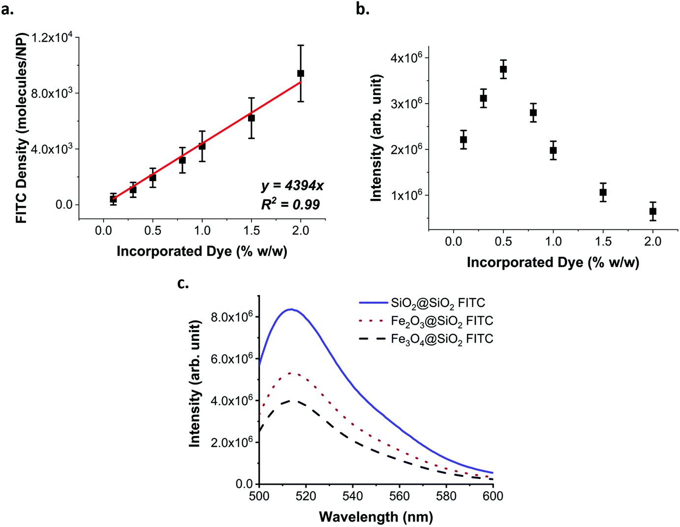 | ||
| Fig. 3 Effect of dye loading and core material on the fluorescence. (a) FITC density (molecules/NP). The error bars correspond to the sum of the instrumental and experimental error. (b) Fluorescence of the silica layer grown on the 60 nm plain-SiO2 core, using different amounts of FITC–APTMS. The error bars correspond to the instrumental error. While the amount of incorporated dye increases linearly, the fluorescence reaches a maximum and then decreases due to ACQ, PCQ and FRET effects. (c) Fluorescence spectra of SiO2@SiO2 FITC, γ-Fe2O3@SiO2 FITC and Fe3O4@SiO2FITC NPs at the same concentration (4 × 10¹⁰ NPs per mL). The presence of the iron oxide cores affects the fluorescence of the core–shell structure absorbing the light emitted from the fluorophore. | ||
The percentage of FITC was calculated based on the amount added during the synthesis and not from the amount of fluorophore actually incorporated. Indeed, we found that despite a complete functionalisation of the FITC with 10 equivalents of APTMS, according to HPLC (ESI Fig. S6†), the incorporation of the dye was only 50–60% effective (ESI Fig. S6†). We attribute this result to the instability of the thiourea bond in alkaline solutions. Considering that the maximum fluorescence efficiency was obtained for the sample loaded with 0.5% w/w, we estimated that an average distance in the range of 5.8 to 6.9 nm between molecules of FITC is necessary before the quenching dominates over the benefit of the loading increase (ESI methods, Fig. S7, 8 and Table S2†).
The optimised parameters for the fluorescence labelling were then applied to the maghemite and magnetite multicore (γ-Fe2O3@SiO2 FITC and Fe3O4@SiO2 FITC respectively) and plain silica core (SiO2@SiO2 FITC) NPs.
The presence of different types of cores affects both the absorbance and fluorescence of the NPs (Fig. 3c, ESI Fig. S9–11†). The fluorescence intensity of the dispersion is inversely related to the absorbance of the cores in the range of the excitation and emission of the fluorophore. In measuring the fluorescence of an absorbing solution or dispersion, it is important to correctly quantify the fluorescence intensity. Indeed, the absorbance of the dispersion impacts the intensity of the light reaching the centre of the cuvette as well as the amount of emitted light reaching the detector. Thus, when comparing the fluorescence of the silica layer, the fluorescence intensity must be corrected to consider the absorbance (ESI methods, Fig. S12†). By correcting the fluorescence intensity of each dispersion for their respective absorbance, it is possible to see that the fluorescence of the silica matrix has the same intensity for all the samples and increases in line with the NP concentration (ESI Fig. S13†). Therefore, the presence of the iron oxide cores affects the overall brightness of the NP dispersions, with Fe3O4 having a larger effect than γ-Fe2O3. However, this effect can be explained by the excitation and emission of the fluorophore being in the same spectral region as the absorbance of the iron oxide cores and not as a result of any energy transfer process that the core may have on the fluorophore, as has been observed in other studies.45
The choice of a different fluorophore with excitation and emission at a different wavelength could prevent this issue. However, because FITC is widely used in biology due to its low cost and compatibility with the commonly used 488 nm laser, we considered it interesting for the scientific community to report a method to overcome the limitations related to the preparation of magnetic particles with this dye.
Optimisation of protective layer
Amorphous silica NPs, obtained via sol–gel processes such as the Stöber method, are known to dissolve at different rates when placed in biological media, dependent on pH and the presence of salts. During degradation, dye-doped NPs release the fluorophore with a consequent decrease in brightness and an increase in background noise. To protect silica NPs from fast dissolution, it is possible to use different strategies that lead to more resistant silica compositions,46,47 such as the arginine-catalysed synthesis mentioned previously.39 However, the presence of amino acids on the NP surface may alter the composition of the biomolecular corona, which is formed when NPs encounter a biological media, and has been shown to be one of the critical factors determining NP uptake and intracellular trafficking.1Here we report a new method of synthesizing a protective layer of silica adapted from Mahon et al.39 It consists of the thermo-catalysed hydrolysis and condensation of TEOS in the absence of any catalytic agent in solution.
Protective layers of different thicknesses were grown by adding different equivalents of TEOS (Fig. 4). The resulting thickness of the protective layer was in agreement with the theoretical value calculated as described in eqn (1) (see the Materials and methods section).
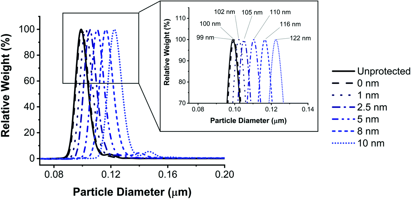 | ||
| Fig. 4 Size characterization of protected FITC doped SiO2 NPs. DCS analysis of FITC doped SiO2 NPs protected using different volumes of TEOS and the inset shows a zoom of the peaks depicting their exact sizes. The thickness of the protective layer formed via the thermal-catalysed method is finely controlled. | ||
The protective properties of the layers (of increasing thickness) were evaluated by incubating the NPs in cell culture media over a range of time periods (0, 4, 8 and 24 h) at 37 °C, then separating the leaked dye from the NPs using sodium dodecyl sulphate-polyacrylamide gel electrophoresis (SDS-PAGE; Fig. 5a). Additionally, some of the cell culture media in which the NPs were incubated was centrifuged to remove the NPs, and the residual fluorescence of the supernatant was measured and plotted against time of incubation (Fig. 5b).
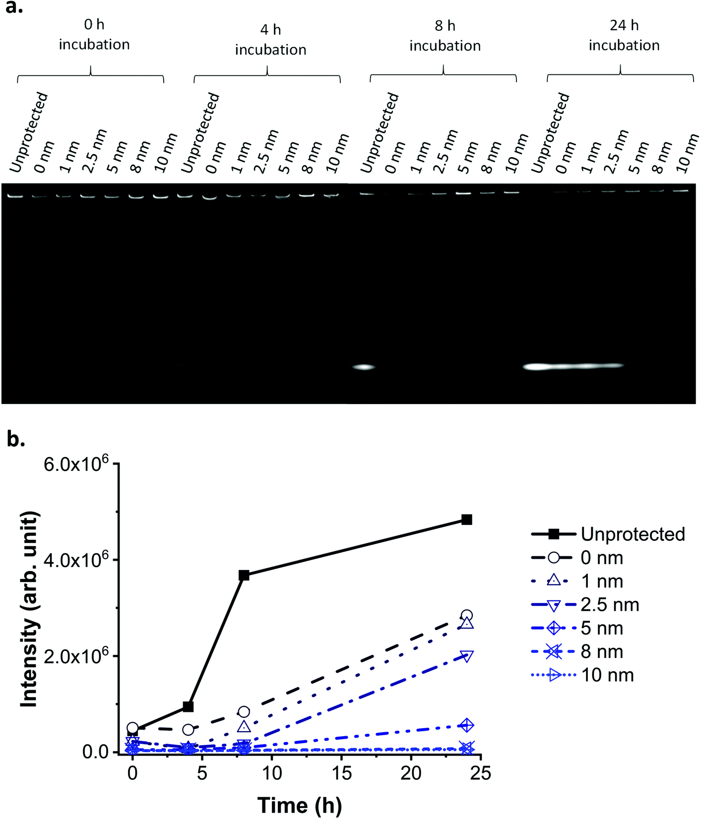 | ||
| Fig. 5 Nanoparticle leaking test in biological media. (a) SDS-PAGE of FITC doped SiO2 NPs with protective layer of different thickness in media after incubation at 37 °C for different time periods. SiO2 NPs are too large to enter the gel and only free dye migrates through the gel. Therefore, the fluorescent bands on the bottom of the gel indicate the presence of free (and hence leaked) FITC. (b) Residual fluorescence in the media after FITC doped SiO2 NPs with protective layer of different thickness were spun down. The protective layer prevents leaking in biological conditions depending on the thickness, with a layer of 8–10 nm required for 24 hours stability. Note: the lines serve as a guide only and do not represent a fit. | ||
A 1 nm layer prevented leaking for up to 4 hours incubation in biological media, while an 8 nm layer prevented leaking for up to 24 hours (Fig. 5). We hypothesise that, following this trend, a layer thicker than 8 nm could prevent leaking for a period even longer than 24 hours. A layer of silica of similar thickness grown under Stöber conditions does not provide the same level of protection against leaking in media (ESI Fig. S14 and S15†), as previously reported also by Mahon et al.39 The residual fluorescence of the NPs in the wells of the SDS-PAGE proves that despite leaking, some of the fluorescence is still detectable after 24 hours for all samples, except for the unprotected one.
Elemental microanalysis (CHN) and IR spectroscopy of the SiO2 NPs before and after protection (ESI methods, Table S3 and Fig. S16†) suggest that the high temperature catalyses the hydrolysis and condensation of TEOS and the removal of residual ethoxy groups from the silica matrix formed under Stöber conditions, thereby leading to the formation of a silica matrix more resistant to dissolution. Furthermore, in the absence of a catalytic agent to catalyse the hydrolysis and condensation of TEOS, it is only the temperature, the surface located acido-basic function Si–O−, and its counter-ion ammonium that serves to catalyse the reaction. Moreover, as TEOS is immiscible with water, only a small amount is available in solution. For these reasons, we hypothesise that these experimental conditions promote the growth of a silica layer by the addition of monomers of hydrolysed or partially hydrolysed TEOS. This mechanism of silica formation, similar to that previously reported by Hristov et al. in 2015,48 would differ significantly to the mechanism involved under the Stöber process, in which it is suggested that the silica matrix is formed by aggregation of nuclei leading to a nanoporous structure lacking condensation.49 However, further investigations are required to unravel the mechanism of the reaction occurring during the protection stage. A decrease of the NPs fluorescence after protection was also observed, mainly due to the degradation of the organic dye during the high temperature treatment (Fig. S17†).
For biological experiments, Fe3O4 NPs were chosen as multicores due to their higher saturation magnetisation compared to the maghemite and the fluorescent layer was protected with a 10 nm layer to prevent leaking for up to 24 hours in media. The final nanoconstructs (Fe3O4@SiO2 FITC-P) were characterized before use and consistency between different batches was preserved (Fig. S18–S20†). The mass magnetisation saturation of the final nanoconstruct (13 Am2 kg−1) is lower than the bare Fe3O4 NPs (80 Am2 kg−1, S21†) which is in agreement with the fact that the diamagnetic SiO2 shell represents about 80% of the mass of the final particle.
Nanoparticle performance in the biological environment
While the particles were shown to not leak dye in cell culture media for up to 24 hours (Fig. 5 and S19c†), the intracellular environment is more complex and constantly evolving, with changes in pH, osmotic pressure and enzymatic activity, especially throughout the endo–lysosomal pathway (through which most NPs are trafficked).50 As such, it is important to ensure that the NPs are stable both during cell exposure (NPs in culture media) and after internalisation (NPs in the intracellular environment). Therefore, the optimised Fe3O4@SiO2 FITC-P NPs were assessed for their suitability for in vitro intracellular imaging and flow cytometry analysis.The fluorescence of the NPs remains stable after 72 hours of cell incubation, and their intracellular location can be clearly identified by confocal microscopy (Fig. 6a). The absence of a green background or diffuse green signal, typical of cells treated with leaky NPs,51 demonstrates the stability of these particles in the dynamic intracellular environment.
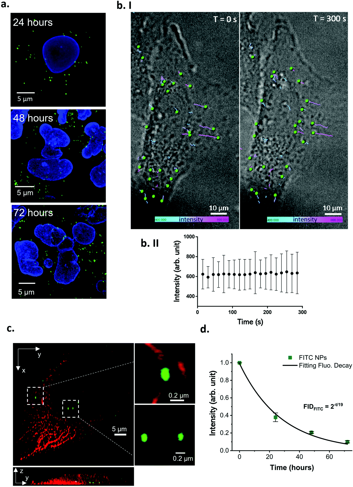 | ||
| Fig. 6 Image analysis of the cell internalized Fe3O4@SiO2 FITC-P NPs. (a) Confocal images of fixed A549 cells treated with 40 μg mL−1 of Fe3O4@SiO2 FITC-P for 2 hours and incubated in fresh culture media for 24, 48 or 72 hours. The nanoparticles are detectable in the intracellular environment as bright punctuated green spots. Blue: cell nuclei, green: Fe3O4@SiO2 FITC-P. Scale bar: 5 μm. (b. I) Live cell imaging time-lapse showing NPs intracellular trafficking after exposing the cells to 40 μg mL−1 for 2 hours. The NPs motion was tracked from T = 0 s (left panel, first frame of the movie) where the NPs are at the beginning of their route, until T = 300 s (right panel, last frame of the movie) where the NPs are at the end of their trajectory (see ESI movie 1† for the real time trajectory generation). The tracked NPs are rendered as green spheres, and their trajectories are presented as color coded lines, representing the single particle fluorescence intensity variation overtime. The minimum intensity (400 arb. unit) is represented in turquoise, the maximum intensity (800 arb. unit) is in pink. A variation in the trajectory color corresponds to a NP FITC intensity variation. Acquisition frequency: 0.06 frames per s. Grey scale: bright field; green: Fe3O4@SiO2 FITC-P, scale bar: 5 μm. (b. II) The mean NP fluorescence intensity remained stable over the entire time-lapse acquisition length (values are expressed as mean ± SD). (c) 3D SRRF super resolution image of A549 cells treated with 40 μg mL−1 of Fe3O4@SiO2 FITC-P. The NPs had adequate emission intensity and photostability to sustain SRRF super resolution imaging. Red: tubulin, green: NPs. Scale bar: 5 μm. (d) Flow cytometry analysis of A549 cells treated with 80 μg mL−1 of Fe3O4@SiO2 FITC-P NPs for 2 hours and cultured in NP-free media for different timepoints. The fluorescence signal from NPs follows a base two exponential decay fitting with a R2 = 0.99. The half-life of the FITC signal is in close agreement with the A549 division time, confirming leaking is absent or negligible (values are expressed as mean ± SD, n = 2). | ||
Observing NP behavior in living cells is a key approach to understanding bio-nano interactions, as it allows the observation of intracellular NP dynamics while avoiding fixative-related artefacts and alterations of the sample. NP uptake kinetics52 and intracellular trajectories can also be investigated using live cell imaging. Multicolor live cell imaging can be used to perform time resolved co-localization studies to understand which compartments of the cell are involved in the response to NP treatment.53 The Fe3O4@SiO2 FITC-P NPs were tested in live cell imaging experiments using two common conditions: long-term/low frequency (i.e. overnight time-lapses, a few frames per hour acquired), typically useful for observing slow cellular responses and trafficking pathways, and short-term/high frequency acquisition (i.e. a few minutes long, many frames per second acquired), typically used to record fast cellular dynamics. In both acquisition formats, the fluorescence intensity of the particles was stable throughout the analysis time (Fig. S22 and S23†) with NP internalisation and intracellular accumulation clearly observed (Fig. 6b).
Furthermore, these NPs were suitable for use in super-resolution radial fluctuations (SRRF) imaging (Fig. 6c), making them ideal for super-resolved intracellular localisation analysis in fixed or live cells, which is a key aspect of drug delivery studies.54 The main drawback associated with super-resolution techniques such as stimulated emission depletion (STED) and stochastic optical reconstruction microscopy (STORM), is the inability to perform live cell analysis. With these methods, the targets are precisely localised based on the intermitting emission of the fluorophore, induced by stimuli such as high intensity laser exposure or reducing buffers that strongly affect live cell viability.55,56 Furthermore, acquisition using these techniques is extremely time consuming, not all the commercially available fluorophores are compatible, and they are easily photobleached under the required acquisition conditions.57 Contrary to other super-resolution techniques, SRRF does not require a blinking fluorophore to achieve a resolution in the order of 30–50 nm,58 instead, it is based on a post-acquisition image analysis of an image sequence composed of hundreds of frames. The algorithm defines the pixel signal as real (generated by a fluorophore) or as not real (background noise) based on the radial symmetry of pixels across the image sequence. The symmetry is greater for fluorophores, as the emission is precisely localized among the frames, and smaller for background noise which is randomly distributed across the image sequence.59 The super-resolved final image is then reconstructed based on the radial symmetry analysis that calculates the original position of the fluorophores and excludes noise, overcoming the Abbe diffraction limit.
Fluorophores employed in SRRF imaging must have adequate emission intensity and photostability to sustain exposure acquisition settings in the order of a few milliseconds and capture in hundreds of sequential frames.59 If these conditions are not met, subsequent image reconstruction can lead to artefacts or failure.54 The Fe3O4@SiO2 FITC-P NPs were bright with a punctuated signal and size in the expected range (ca. 0.1 μm) when imaged using SRRF super resolution microscopy. They could be easily seen interacting with tubulin (red filaments, top inset Fig. 6c), a main component of the cell cytoskeleton that plays a role in the movement of vesicles through the endo–lysosomal pathway (which most NPs are processed through). The ability to precisely identify the location of NPs during their interaction with cells is critically important for overcoming the main limitations in nanomedicine, and the use of these Fe3O4@SiO2 FITC-P NPs in conjunction with SRRF microscopy provides adequate resolution for in-depth intracellular particle trafficking studies.
The intracellular stability of the NPs was also confirmed by flow cytometry analysis (Fig. 6d and Fig. S23†). The FITC intensity per cell was monitored for up to 72 hours and the signal decreased in an exponential fashion, with a halving time of the FITC signal (about 19 hours, see ESI† methods) close to the division time of the cell line (dividing cells will split their NP load, resulting in a reduction in the FITC signal per cell that is unrelated to dye leaking).60 Cells treated with leaking NPs typically show a significant loss of fluorescence at a greater rate than proliferation.60 Thus, the flow cytometry analysis supports the determination that the fluorescence of these particles is stable intracellularly up to 72 hours.
In addition to the effective fluorescent properties of these NPs, the magnetic multicore offers the advantage of easy extraction from complex biological solutions, providing the opportunity for analysis of many aspects of the NP interactions with the biological machinery.
To demonstrate that the NPs can be harvested after cell internalisation, A549 cells were incubated with the Fe3O4@SiO2 FITC-P NPs for 24 hours, after which the cells were collected and lysed. The NPs were then recovered from the lysate by magnetic extraction. The protein profile associated with the cell extracted particles is significantly different to that of the simple Fe3O4@SiO2 FITC-P NPs with hard corona (pre-formed in complete medium (cMEM)) before cell incubation (see Materials and methods for further information; Fig. 7a). Interestingly, the protein content per NP in the extracted sample is much higher than that of the pre-formed biomolecular corona (ESI Fig. S24†). Particles and biological structures were identified in the magnetically extracted population by TEM analysis (ESI Fig. S25†). Of particular interest was the observation that the NPs were contained within intact vesicle-like structures (Fig. 7b). This finding demonstrates the potential to harvest internalised particles from the intracellular environment while successfully preserving the biological structures in which they are encapsulated and highlights their potential use as a tool to analyse the processes that regulate intracellular trafficking.2
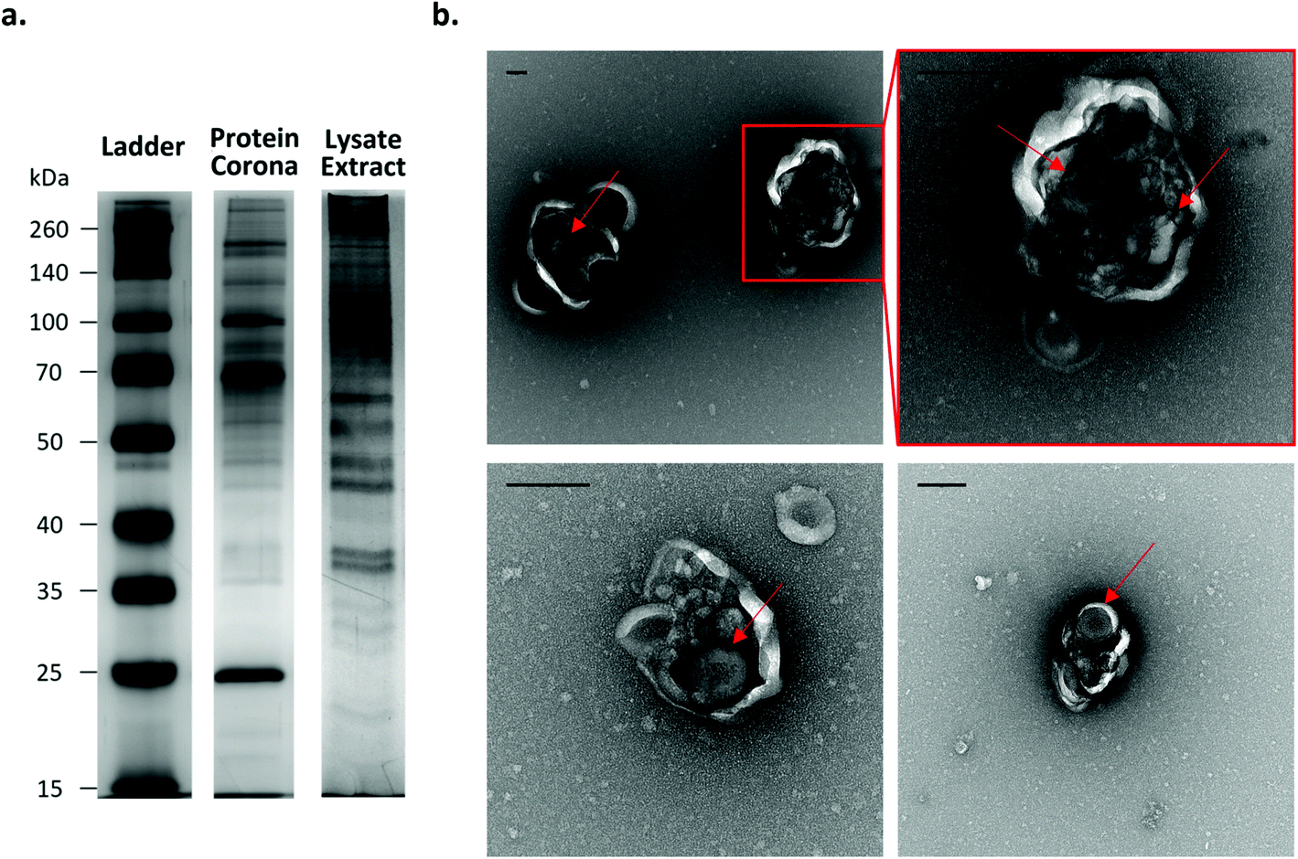 | ||
| Fig. 7 Analysis of Fe3O4@SiO2 FITC-P NPs after cell internalization. (a) Comparison of protein composition of Fe3O4@SiO2 FITC-P protein corona before and after incubation in A549 cells by silver-stained SDS-PAGE gel. The protein profile of the NPs extracted from the intracellular environment is significantly different, indicating they have retained proteins from their intracellular environment. (b) TEM imaging of extracted NPs reveals they are contained within vesicle like structures (scale bar: 200 nm). Arrows were added to help the reader to identify the particles. | ||
Conclusions
Investigating the interactions of NPs with cells usually relies on a combination of techniques such as fluorescence microscopy, flow cytometry and proteomics. However, the cross-interpretation of the results can be challenging due to the lack of correlation when different NP systems are required. Fluorescent microscopy is one of the most powerful techniques for investigating intracellular organization as it allows NPs to be imaged after internalisation in cells. However, fluorescent microscopy relies on the labelling of specific biomolecules and so has limited capacity for identifying the interaction partners of NPs. Magnetic NPs can be easily extracted from a biological media by magnetic extraction, and the interacting biomolecules can be co-extracted with the NPs and identified. Multifunctional NPs may provide a solution to these challenges.In this study, we presented the design and optimisation of multifunctional magnetic and fluorescent NPs that are suitable for the most common imaging techniques and also the extraction of cell compartments involved in their intracellular trafficking. The NP fluorescence intensity is derived from a fluorescein-based dye covalently encapsulated in a silica layer on the particle. The brightness and stability of these NPs was shown to be compatible with imaging techniques such as confocal microscopy, 3D SRRF imaging and live cell imaging. The particles were designed to minimise silica degradation in biological environments which would induce the loss of the dye during live imaging. The fluorescence of the particles was easily detected in the cell after 72 h, demonstrating their ability to be tracked over extended time periods. We also showed that, owing to the magnetic multicore, the internalized NPs could be extracted from the cell after lysis enabling the analysis of the proteins involved in their intracellular trafficking. This new construct could open the way to the correlation of the intracellular location of the NPs with the identification of the biomolecules interacting with them.
Materials and methods
Synthesis of SiO2 cores
The synthesis of the SiO2 NPs was based on a two-step seed-growth process adapted from a synthesis already reported.61 Briefly, a solution made of 21.6 mL of ethanol and 240 μL of TEOS (Sigma – 131903) was added quickly to a solution composed of 21.6 mL of ethanol, 114 μL of MilliQ water, and 1.18 mL of NH3 35% (Fisher – 10659263). The mixture was allowed to react at room temperature for 12 hours, resulting in SiO2 NPs of about 15 nm in diameter. Seven millilitres of the resulting dispersion were added in a solution containing 57.8 mL of ethanol, 19.6 mL of MilliQ water and 1.12 mL of ammonia solution 35%. TEOS was added in 100 μL aliquots to the reaction solution and the growth of the NPs was monitored by dynamic light scattering (DLS) until the size of 86 nm was obtained.Synthesis of Fe3O4 NPs
Magnetite NPs were synthesized by a coprecipitation method.62,63 In a typical synthesis, 0.030 mol of FeCl3·6H2O (Sigma – 31232) were dissolved in 350 mL of milliQ water, while 0.015 mol of FeCl2·4H2O (Sigma – 44939) were dissolved in 17 mL of HCl 1.5 M. The two iron solutions were combined under vigorous mechanical stirring resulting in a light-yellow solution. While stirring, 30 mL of ammonia solution 35% were added to the iron solution and the formation of iron oxide NPs was immediately observed.After 15 minutes NPs were precipitated by magnetic decantation and washed 3 times with water before being redispersed in a slightly acidic aqueous solution of hydrochloric acid.
Synthesis of γ-Fe2O3 NPs
The synthesis of the γ-Fe2O3 NPs was carried out as reported by Mornet et al.63 Briefly, Fe3O4 nanoparticles were synthesised as described above but after washing three times in water, 50 mL of HNO3 2 M was added and the particles were stirred for 15 minutes. NPs were precipitated and redispersed in 60 mL of Fe(III) nitrate 0.3 M and boiled for 30 minutes; a colour change from black to rust brown was observed. The solution was allowed to cool at room temperature before the NPs were precipitated by magnetic decantation. After removal of the supernatant, 50 mL of HNO3 2 M was added and the particles were stirred for 15 minutes. Then, NPs were precipitated by magnetic decantation and the pellet washed 4 times with acetone before being redispersed in MilliQ water. Trace acetone was removed by rotary evaporator.Synthesis of iron oxide multicores
The synthesis of the iron oxide multicores and their encapsulation in a silica matrix was adapted from a procedure described by Yammine et al.40 Briefly, for the synthesis of multicores, iron oxide NPs were transferred in cyclohexane, by coating them with oleic acid according to the procedure described by Van Ewijk et al.64 Five millilitres of the hydrophobic ferrofluid at 50 mg mL−1 were mixed with a solution of SDS 50 mM and emulsified in a 25 mL round bottom flask, with a tip sonicator (Vibra-cell™ VCX 750) (time: 20 min; amplitude: 40%; pulse: 2 s on, 3 s off) in an ice bath. The emulsion was then transferred in a 100 mL round bottom flask and heated to 80 °C with a soft flow of air for 90 minutes, to evaporate the cyclohexane (water was added when necessary to prevent drying of the sample). The dispersion was then diluted with MilliQ water to reach a total volume of 50 mL and heated to 40 °C. Under stirring, 2.5 mL of ammonia solution (35%) were added together with 250 μL of TEOS. After 2 hours the dispersion was diluted by addition of 200 mL of water and precipitated by centrifugation. The supernatant was discarded, and the pellet redispersed in water (20 mL).A basic hydroalcoholic solution of 72 mL of ethanol, 4.4 mL of ammonia solution 35% and 100 μL of TEOS was prepared and the particles dispersed in water were added to this solution under stirring. After 30 minutes, a second aliquot of 200 μL of TEOS was added followed by another aliquot of 300 μL after other 30 minutes. The reaction was left for 2 hours, before the ammonia was evaporated by rotavapor and NPs precipitated by centrifugation. The pellet was washed three times and redispersed in 20 mL of milliQ water. Aggregates were spun down at 600g for 10 minutes.
Dye solution preparation
Synthesis of fluorescent shell for SiO2 cores
For the synthesis of the fluorescent shell, 2 mL of SiO2 cores in the growing solution were transferred in a reaction tube. An aliquot of 20 μL of TEOS was added followed by a 16 μL aliquot of dye solution (this volume provides an incorporation of APTMS–FITC of 0.5%, in the course of the dye loading study, this volume was adjusted to give the desired percentage). After 30 minutes, a second aliquot of 40 μL of TEOS and 32 μL of dye solution was added to the reaction solution followed, after another 30 minutes, by a third aliquot of 40 μL of TEOS and 32 μL of dye solution. The reaction was considered finished 2 hours after the last addition of TEOS, at room temperature.The reaction solution was diluted 1 in 5 in milliQ water before being precipitated by centrifugation. The pellet was washed 3 times with water and then redispersed in water.
Synthesis of fluorescent shell for magnetic multicores
For the synthesis of the fluorescent shell on iron oxide multicores, 7 mL of a dispersion 7 mg mL−1 of multicores were added in a reaction solution made of 25.7 mL ethanol and 1.6 mL of ammonia solution 35%. An aliquot of 100 μL of TEOS was added at the same time with 80 μL of dye solution. After 30 minutes, a second aliquot of 200 μL of TEOS and 160 μL of dye solution were added and after a further 30 minutes a third aliquot of 200 μL of TEOS and 160 μL of dye solution were added. The reaction was left for 2 hours at room temperature until completion. The reaction solution was diluted 1 in 5 in milliQ water before being precipitated by centrifugation. The pellet was washed 3 times with water and then was redispersed in water. Potential aggregates were removed by centrifuging at 600g for 10 minutes.Synthesis of the protective layer
A dispersion of SiO2 NPs 20 mg mL−1 was heated to 90 °C and an aliquot of TEOS added. The volume of TEOS to be added can be calculated by the following formula: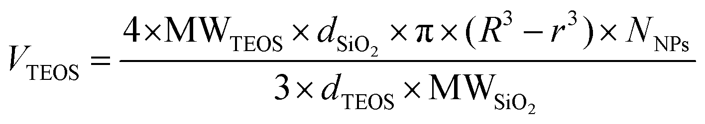 | (1) |
A first aliquot equal to half of the total volume was added to the dispersion while heating to 90 °C and a second aliquot added after 1 hour. The reaction was left for 3 hours at 90 °C until completion. The NPs were then allowed to cool to room temperature, and then were spun down by centrifugation and washed three times with distilled water, before being redispersed in water.
Leaking test
NPs were incubated in minimum essential medium (MEM) supplemented with 10% foetal bovine serum (FBS, Gibco), 1% penicillin–streptomycin (Invitrogen) at a concentration of 0.1 mg mL−1 at 37 °C for 0, 4, 8 and 24 hours. 20 μL of such solution were then mixed with a 10× SDS loading buffer (New England Biolabs) and loaded in a gel 10% polyacrylamide. The gel was run at 200 mV for 30 minutes and imaging performed with Syngene G-Box XT4 equipped with a 525 nm filter and a blue light.Cell culture
The A549 non-small lung carcinoma (ATCC® CCL-185™) cell line was purchased from ATCC, and cultured in MEM (Gibco™) supplemented with 10% FBS (Gibco™) and 50 U mL−1 penicillin–streptomycin (Gibco™). Cells were grown at 37 °C in a humidified atmosphere of 5% CO2 and sub-cultured at 70–80% confluence using trypsin (0.25% in EDTA; Gibco™). Cells were screened monthly for mycoplasma contamination using the MycoAlert™ Mycoplasma Detection Kit, and all cultures were free of contamination for the duration of experiments reported.Fe3O4@SiO2 FITC-P NPs corona preparation
Fe3O4@SiO2 FITC-P NPs were incubated in cMEM (MEM supplemented with 10% FBS (Gibco) and 1% penicillin–streptomycin, Invitrogen) at a concentration of 0.8 mg mL−1 at 37 °C for 1 hour. For the SDS-PAGE experiments, the NPs in cMEM were precipitated by centrifugation and redispersed in phosphate-buffered saline (PBS) and then washed twice with PBS by precipitation for magnetic decantation.Exposure of cells to NPs
Cells were seeded at a density of 6 × 10⁶ cells per flask in T175 flasks (Grenier) for extraction experiments. After seeding, cells were incubated for 48 hours before exposure to the NP dispersion. Fe3O4@SiO2 FITC-P NPs with in situ corona were incubated at a concentration of 0.8 mg mL−1 with the cells for 10 minutes, then the non-internalized NPs were discarded and after two washes with Dulbecco's phosphate-buffered saline (DPBS) and two washes in cMEM. The cells were then incubated with fresh cMEM (without NPs) for a further 8–24 hours.Spinning disk confocal imaging
Cells were imaged in a 96-well glass bottom plates (CellVis) on a Nikon eclipse TI spinning disc confocal microscope. For the samples shown in Fig. 6a and c, the cells were fixed with 4% paraformaldehyde and stained with DAPI (2 μg mL−1, Fig. 6a) to visualise the cell nucleus; or permeabilised with 1% w/w saponin and immunostained with anti-tubulin antibody (Thermo Fisher, A11126) in combination with AlexaFluor-546 secondary antibody (Thermo Fisher, A11035). For live cells imaging shown in Fig. 6b and ESI Fig. S22,† the cells were imaged in phenol-free CMEM, in a live cell chamber at 37 °C with 5% CO2. The images and the time-lapses were analyzed with Imaris imaging software (Bitplane).Nanoparticle uptake assessment by flow cytometry
To prepare the cells for flow cytometry analysis, 50000 cells per well were seeded in a 24-well plate. After incubation with the nanoparticles, the cells were harvested by trypsinisation and washed twice in PBS. The cells were then fixed in 4% paraformaldehyde and stored in PBS at 4 °C. To assess the NP dilution, the cells were run in a Cytoflex LX (Beckman Coulter) flow cytometer. The fluorescent signal per cell was measured (excitation/emission 488/530 nm for NPs) for ≥50000 events collected in the P2 population (single cells gate, gating shown in ESI Fig. S23†).
Cell lysis
The cell culture media was discarded, and the cells were washed with 10 mL of PBS per flask. The PBS was discarded, and the cells were incubated with 5 mL per flask of trypsin at 37 °C for 10 minutes. The trypsin was deactivated by adding 5 mL per flask of cMEM supplemented with 10% FBS. The cell dispersion was transferred in a Falcon tube and cells were precipitated by centrifugation and washed once with PBS. 15 × 106 cells were redispersed in 4.5 mL of lysis buffer (0.01× potassium phosphate-buffered saline (KPBS) + protease inhibitor) and allowed to swell for 10 minutes in ice. Cells were loaded in a Dounce homogenizer and lysed with 12 consecutive hits. The lysis buffer was neutralized adding 500 μL of 10× KPBS.SDS-PAGE
For SDS-PAGE, the lysate was extracted in a three-pole magnet for 8 hours at 4 °C, the supernatant was discarded, and the pellet redispersed in PBS. The pellet was extracted once more for 12 hours at 4 °C and redispersed in PBS. The concentration of NPs in the extracted lysate was estimated by fluorescence measurement by interpolation on a calibration line.Fe3O4@SiO2 FITC-P NPs with hard protein corona and those extracted from the cell lysate were boiled for 10 minutes in the presence of 1,4-dithiothreitol (DTT, New England Biolabs) as a reducing agent. The samples were loaded in a 10% polyacrylamide gel and gel electrophoresis was performed at 110 mV for 75 minutes. To detect the separated proteins, the gels were stained using the Pierce™ Silver Stain Kit. Imaging was performed with Syngene G-Box XT4 equipped with a UV filter and a white light source.
TEM Negative staining
For TEM imaging, the cell lysate was processed with MS magnetic columns (Miltenyi Biotec). The magnetic fraction of the cell lysate was absorbed onto hydrophilized (PELCO easiGlow™) 200-mesh carbon/Formar coated Copper grids (TedPella, 01800). The samples were then further fixed with 2.5 wt% glutaraldehyde (Sigma-Aldrich, G7651) and 2% formaldehyde (Thermo Fisher Scientific, 28906) in 0.1 M sodium phosphate buffer, pH = 7.4 and negatively stained with a solution of 1 wt% uranyl acetate (Agar Scientific, R1260A) and 0.1 wt%. Trehalose (Sigma – Aldrich, T9449). The addition of 0.1 wt% trehalose to the staining solution aimed to improve the preservation of biological material during dehydration. The grids were left to air dry and representative TEM micrographs were obtained with FEI Tecnai G2 20 Twin operating at 200 kV.Rights retention statement
This publication has emanated from research supported in part by grants from Science Foundation Ireland under Grant numbers 17/NSFC/4898, 17/ERCD/4962 and 15/SIRG/3423. For the purpose of Open Access, the author has applied a CC BY public copyright licence to any Author Accepted Manuscript version arising from this submission.Author contributions
Lorenzo Cursi: conceptualization, data curation (NPs synthesis, characterization, biological application), writing-original draft preparation, investigation, methodology; Silvia Vercellino: data curation (optical imaging), investigation, methodology, writing-reviewing and editing; Mura McCafferty: conceptualization, investigation, data curation (flow cytometry), writing-reviewing and editing; Emily Sheridan: data curation (TEM imaging), writing-reviewing and editing, investigation; Vanya Petseva: methodology (TEM imaging), writing-reviewing and editing, investigation; Laurent Adumeau: conceptualization, supervision, writing-reviewing and editing; Kenneth A. Dawson: supervision, conceptualization, writing-reviewing and editing.Conflicts of interest
There are no conflicts to declare.Acknowledgements
KAD, LA, ES and SV acknowledge that this publication has emanated from research supported in part by grants from Science Foundation Ireland [17/NSFC/4898 (KAD, LA and ES), 17/ERCD/4962 (KAD) and 15/SIRG/3423 (SV)]. LC and VP acknowledge this work was part-funded by the Celtic Advanced Life Science Innovation Network (CALIN), an Ireland-Wales INTERREG project part-funded by the European Regional Development Fund through the Welsh Government, agreement no.80885. SV also acknowledges support by the PhD Research Scholarship from the UCD School of Biomolecular and Biomedical Science. MMC acknowledges the support of the Irish Research Council Enterprise Partnership Scheme (Postdoctoral) 2019 – EPSPD/2019/232. The authors acknowledge Dr. D. Scholtz and Dr. A. Blanco from the imaging and flow cytometry core facilities of the Conway Institute of Biomolecular and Biomedical Research Centre at University College Dublin for their assistance. The authors acknowledge Delyan Hristov and Eugene Mahon for their pioneering studies on the concept of the protective layer without arginine catalysis. The authors also wish to thank Dr James Sullivan's group (University College Dublin) for the use of the IR spectrophotometer, Rui Zhang and Dr Munuswamy Venkastesan (Trinity College Dublin) for their help with the magnetic measurements and Dr Ruth Doherty (CBNI) for her kind support with the preparation of the manuscript. Niamh O'Raw and Sophie Fernan are also acknowledged for their supporting work.References
- K. A. Dawson and Y. Yan, Nat. Nanotechnol., 2021, 16, 229–242 CrossRef CAS PubMed.
- E. Sheridan, S. Vercellino, L. Cursi, L. Adumeau, J. A. Behan and K. A. Dawson, Nanoscale Adv., 2021, 3, 2397–2410 RSC.
- W. Wu, J. Changzhong and V. A. L. Roy, Nanoscale, 2015, 7, 38–58 RSC.
- D. Alex, A. Mathew and R. K. Sukumaran, Bioresour. Technol., 2014, 167, 547–550 CrossRef CAS PubMed.
- K. Li, Y. Fan, Y. He, L. Zeng, X. Han and Y. Yan, Sci. Rep., 2017, 7, 16473 CrossRef PubMed.
- E. Amstad, S. Zurcher, A. Mashaghi, J. Y. Wong, M. Textor and E. Reimhult, Small, 2009, 5, 1334–1342 CrossRef CAS PubMed.
- J.-s. Choi, S. Kim, D. Yoo, T.-H. Shin, H. Kim, M. D. Gomes, S. H. Kim, A. Pines and J. Cheon, Nat. Mater., 2017, 16, 537–542 CrossRef CAS PubMed.
- S. M. Dadfar, K. Roemhild, N. I. Drude, S. von Stillfried, R. Knüchel, F. Kiessling and T. Lammers, Adv. Drug Delivery Rev., 2019, 138, 302–325 CrossRef CAS PubMed.
- I. Rubia-Rodríguez, A. Santana-Otero, S. Spassov, E. Tombácz, C. Johansson, P. De La Presa, F. J. Teran, M. d. P. Morales, S. Veintemillas-Verdaguer, N. T. K. Thanh, M. O. Besenhard, C. Wilhelm, F. Gazeau, Q. Harmer, E. Mayes, B. B. Manshian, S. J. Soenen, Y. Gu, Á. Millán, E. K. Efthimiadou, J. Gaudet, P. Goodwill, J. Mansfield, U. Steinhoff, J. Wells, F. Wiekhorst and D. Ortega, Materials, 2021, 14, 706 CrossRef PubMed.
- P. Guardia, R. Di Corato, L. Lartigue, C. Wilhelm, A. Espinosa, M. Garcia-Hernandez, F. Gazeau, L. Manna and T. Pellegrino, ACS Nano, 2012, 6, 3080–3091 CrossRef CAS PubMed.
- E. A. Périgo, G. Hemery, O. Sandre, D. Ortega, E. Garaio, F. Plazaola and F. J. Teran, Appl. Phys. Rev., 2015, 2, 041302 Search PubMed.
- M. K. Masud, J. Na, M. Younus, M. S. A. Hossain, Y. Bando, M. J. A. Shiddiky and Y. Yamauchi, Chem. Soc. Rev., 2019, 48, 5717–5751 RSC.
- F. Bertoli, G. L. Davies, M. P. Monopoli, M. Moloney, Y. K. Gun'ko, A. Salvati and K. A. Dawson, Small, 2014, 10, 3307–3315 CrossRef CAS PubMed.
- H. M. Pezzi, D. J. Niles, J. L. Schehr, D. J. Beebe and J. M. Lang, ACS Omega, 2018, 3, 3908–3917 CrossRef CAS PubMed.
- H.-W. Chen, Z.-S. Fang, Y.-T. Chen, Y.-I. Chen, B.-Y. Yao, J.-Y. Cheng, C.-Y. Chien, Y.-C. Chang and C.-M. J. Hu, ACS Appl. Mater. Interfaces, 2017, 9, 39953–39961 CrossRef CAS PubMed.
- M. I. J. Denison, S. Raman, N. Duraisamy, R. M. Thangavelu, S. U. M. Riyaz, D. Gunasekaran and K. Krishnan, RSC Adv., 2015, 5, 99820–99831 RSC.
- B. Banik, B. W. Askins and S. Dhar, Nanoscale, 2016, 8, 19581–19591 RSC.
- C. V. Mura, M. I. Becker, A. Orellana and D. Wolff, J. Immunol. Methods, 2002, 260, 263–271 CrossRef CAS PubMed.
- E. Ximendes, R. Marin, Y. Shen, D. Ruiz, D. Gómez-Cerezo, P. Rodríguez-Sevilla, J. Lifante, P. X. Viveros-Méndez, F. Gámez, D. García-Soriano, G. Salas, C. Zalbidea, A. Espinosa, A. Benayas, N. García-Carrillo, L. Cussó, M. Desco, F. J. Teran, B. H. Juárez and D. Jaque, Adv. Mater., 2021, 33, 2100077 CrossRef CAS PubMed.
- T. Fontecave, M. Bourbousson, C. Chaneac, C. Wilhelm, A. Espinosa, M.-A. Fortin, C. Sanchez and C. Boissiere, New J. Chem., 2016, 40, 4436–4446 RSC.
- J. Reguera, D. J. d. Aberasturi, M. Henriksen-Lacey, J. Langer, A. Espinosa, B. Szczupak, C. Wilhelm and L. M. Liz-Marzán, Nanoscale, 2017, 9, 9467–9480 RSC.
- F. Bertoli, D. Garry, M. P. Monopoli, A. Salvati and K. A. Dawson, ACS Nano, 2016, 10, 10471–10479 CrossRef CAS PubMed.
- M. B. Cutrona and J. C. Simpson, Small, 2019, 15, 1902033 CrossRef PubMed.
- S. Lara, F. Alnasser, E. Polo, D. Garry, M. C. Lo Giudice, D. R. Hristov, L. Rocks, A. Salvati, Y. Yan and K. A. Dawson, ACS Nano, 2017, 11, 1884–1893 CrossRef CAS PubMed.
- A. Ditsch, S. Lindenmann, P. E. Laibinis, D. I. C. Wang and T. A. Hatton, Ind. Eng. Chem. Res., 2005, 44, 6824–6836 CrossRef CAS.
- S. Gyergyek, D. Makovec, A. Mertelj, M. Huskić and M. Drofenik, Colloids Surf., A, 2010, 366, 113–119 CrossRef CAS.
- S. A. Ansari, E. Ficiarà, F. A. Ruffinatti, I. Stura, M. Argenziano, O. Abollino, R. Cavalli, C. Guiot and F. D’Agata, Materials, 2019, 12, 465 CrossRef CAS PubMed.
- H. Ow, D. R. Larson, M. Srivastava, B. A. Baird, W. W. Webb and U. Wiesner, Nano Lett., 2005, 5, 113–117 CrossRef CAS PubMed.
- A. Van Blaaderen and A. Vrij, Langmuir, 1992, 8, 2921–2931 CrossRef CAS.
- V. Gubala, G. Giovannini, F. Kunc, M. P. Monopoli and C. J. Moore, Cancer Nanotechnol., 2020, 11, 1 CrossRef CAS.
- S. Foglia, M. Ledda, D. Fioretti, G. Iucci, M. Papi, G. Capellini, M. G. Lolli, S. Grimaldi, M. Rinaldi and A. Lisi, Sci. Rep., 2017, 7, 46513 CrossRef CAS PubMed.
- S. A. McCarthy, G.-L. Davies and Y. K. Gun'ko, Nat. Protoc., 2012, 7, 1677–1693 CrossRef CAS PubMed.
- J. Wan, X. Meng, E. Liu and K. Chen, Nanotechnology, 2010, 21, 235104 CrossRef PubMed.
- O. Chen, L. Riedemann, F. Etoc, H. Herrmann, M. Coppey, M. Barch, C. T. Farrar, J. Zhao, O. T. Bruns, H. Wei, P. Guo, J. Cui, R. Jensen, Y. Chen, D. K. Harris, J. M. Cordero, Z. Wang, A. Jasanoff, D. Fukumura, R. Reimer, M. Dahan, R. K. Jain and M. G. Bawendi, Nat. Commun., 2014, 5, 5093 CrossRef CAS PubMed.
- L. Adumeau, C. Genevois, L. Roudier, C. Schatz, F. Couillaud and S. Mornet, Biochim. Biophys. Acta, Gen. Subj., 2017, 1861, 1587–1596 CrossRef CAS PubMed.
- C. J. Moore, G. Giovannini, F. Kunc, A. J. Hall and V. Gubala, J. Mater. Chem. B, 2017, 5, 5564–5572 RSC.
- G. Battistelli, A. Cantelli, G. Guidetti, J. Manzi and M. Montalti, WIREs Nanomed. Nanobiotechnol., 2016, 8, 139–150 CrossRef CAS PubMed.
- S.-A. Yang, S. Choi, S. M. Jeon and J. Yu, Sci. Rep., 2018, 8, 185 CrossRef PubMed.
- E. Mahon, D. R. Hristov and K. A. Dawson, Chem. Commun., 2012, 48, 7970–7972 RSC.
- E. Yammine, L. Adumeau, M. Abboud, S. Mornet, M. Nakhl and E. Duguet, Nanomaterials, 2021, 11, 147 CrossRef CAS.
- A. Burns, P. Sengupta, T. Zedayko, B. Baird and U. Wiesner, Small, 2006, 2, 723–726 CrossRef CAS PubMed.
- T. Fontecave, C. Sanchez, T. Azaïs and C. Boissière, Chem. Mater., 2012, 24, 4326–4336 CrossRef CAS.
- E. Bindini, Z. Chehadi, M. Faustini, P.-A. Albouy, D. Grosso, A. Cattoni, C. Chanéac, O. Azzaroni, C. Sanchez and C. Boissière, ACS Appl. Mater. Interfaces, 2020, 12, 13598–13612 CrossRef CAS PubMed.
- G. Canton, R. Riccò, F. Marinello, S. Carmignato and F. Enrichi, J. Nanopart. Res., 2011, 13, 4349–4356 CrossRef CAS.
- S. A. Corr, Y. P. Rakovich and Y. K. Gun'ko, Nanoscale Res. Lett., 2008, 3, 87 CrossRef CAS.
- T. Yokoi, Y. Sakamoto, O. Terasaki, Y. Kubota, T. Okubo and T. Tatsumi, J. Am. Chem. Soc., 2006, 128, 13664–13665 CrossRef CAS PubMed.
- K. D. Hartlen, A. P. T. Athanasopoulos and V. Kitaev, Langmuir, 2008, 24, 1714–1720 CrossRef CAS PubMed.
- D. R. Hristov, E. Mahon and K. A. Dawson, Chem. Commun., 2015, 51, 17420–17423 RSC.
- V. M. Masalov, N. S. Sukhinina, E. A. Kudrenko and G. A. Emelchenko, Nanotechnology, 2011, 22, 275718 CrossRef CAS PubMed.
- A. M. Milosevic, L. Rodriguez-Lorenzo, S. Balog, C. A. Monnier, A. Petri-Fink and B. Rothen-Rutishauser, Angew. Chem., Int. Ed., 2017, 56, 13382–13386 CrossRef CAS PubMed.
- T. Tenuta, M. P. Monopoli, J. Kim, A. Salvati, K. A. Dawson, P. Sandin and I. Lynch, PLoS One, 2011, 6, e25556 CrossRef CAS PubMed.
- T. dos Santos, J. Varela, I. Lynch, A. Salvati and K. A. Dawson, Small, 2011, 7, 3341–3349 CrossRef CAS PubMed.
- P. Sandin, L. W. Fitzpatrick, J. C. Simpson and K. A. Dawson, ACS Nano, 2012, 6, 1513–1521 CrossRef CAS PubMed.
- T. Andrian, R. Riera, S. Pujals and L. Albertazzi, Nanoscale Adv., 2021, 3, 10–23 RSC.
- M. J. Rust, M. Bates and X. Zhuang, Nat. Methods, 2006, 3, 793–796 CrossRef CAS PubMed.
- R. Heintzmann and T. Huser, Chem. Rev., 2017, 117, 13890–13908 CrossRef CAS PubMed.
- A. G. Godin, B. Lounis and L. Cognet, Biophys. J., 2014, 107, 1777–1784 CrossRef CAS PubMed.
- N. Gustafsson, S. Culley, G. Ashdown, D. M. Owen, P. M. Pereira and R. Henriques, Nat. Commun., 2016, 7, 12471 CrossRef CAS PubMed.
- S. Culley, K. L. Tosheva, P. M. Pereira and R. Henriques, Int. J. Biochem. Cell Biol., 2018, 101, 74–79 CrossRef CAS PubMed.
- A. Salvati, C. Åberg, T. dos Santos, J. Varela, P. Pinto, I. Lynch and K. A. Dawson, Nanomedicine, 2011, 7, 818–826 CrossRef CAS PubMed.
- N. Reinhardt, L. Adumeau, O. Lambert, S. Ravaine and S. Mornet, J. Phys. Chem. B, 2015, 119, 6401–6411 CrossRef CAS PubMed.
- S. Mornet, J. Portier and E. Duguet, J. Magn. Magn. Mater., 2005, 293, 127–134 CrossRef CAS.
- S. Mornet, Synthèse et modification chimique de la surface de nanoparticules de maghémite à des fins d'applications biomédicales, PhD thesis, Université Sciences et Technologies, Bordeaux I, 2002 Search PubMed.
- G. A. van Ewijk, G. J. Vroege and A. P. Philipse, J. Magn. Magn. Mater., 1999, 201, 31–33 CrossRef CAS.
- D. L. Green, J. S. Lin, Y.-F. Lam, M. Z. C. Hu, D. W. Schaefer and M. T. Harris, J. Colloid Interface Sci., 2003, 266, 346–358 CrossRef CAS PubMed.
Footnotes |
| † Electronic supplementary information (ESI) available. See DOI: 10.1039/d1nr04582b |
| ‡ Lorenzo Cursi and Silvia Vercellino contributed equally to this manuscript. |
| This journal is © The Royal Society of Chemistry 2021 |