
 Open Access Article
 This Open Access Article is licensed under a Creative Commons Attribution-Non Commercial 3.0 Unported Licence
Effects of polyethylene glycol on the surface of nanoparticles for targeted drug delivery
Liwang
Shi†
 a,
Jinqiu
Zhang†
b,
Man
Zhao†
a,
Shukun
Tang
a,
Xu
Cheng
a,
Wenyuan
Zhang
a,
Wenhua
Li
a,
Xiaoying
Liu
a,
Haisheng
Peng
*a and
Qun
Wang
*c
a,
Jinqiu
Zhang†
b,
Man
Zhao†
a,
Shukun
Tang
a,
Xu
Cheng
a,
Wenyuan
Zhang
a,
Wenhua
Li
a,
Xiaoying
Liu
a,
Haisheng
Peng
*a and
Qun
Wang
*c
aDepartment of Pharmaceutics, Daqing Campus of Harbin Medical University, 1 Xinyang Rd., Daqing 163319, China. E-mail: fisher1688@163.com; Fax: +86-459-8977588; Tel: +86-459-8153 003
bDepartment of Foreign language, Daqing Normal University, Xibin Rd., Daqing 163712, China
cDepartment of Chemical and Biological Engineering, Iowa State University, Ames, IA 50011, USA. E-mail: qunwang@iastate.edu; Fax: +(515) 294-8216; Tel: +(515) 294-4218
First published on 14th May 2021
Abstract
The rapid development of drug nanocarriers has benefited from the surface hydrophilic polymers of particles, which has improved the pharmacokinetics of the drugs. Polyethylene glycol (PEG) is a kind of polymeric material with unique hydrophilicity and electrical neutrality. PEG coating is a crucial factor to improve the biophysical and chemical properties of nanoparticles and is widely studied. Protein adherence and macrophage removal are effectively relieved due to the existence of PEG on the particles. This review discusses the PEGylation methods of nanoparticles and related techniques that have been used to detect the PEG coverage density and thickness on the surface of the nanoparticles in recent years. The molecular weight (MW) and coverage density of the PEG coating on the surface of nanoparticles are then described to explain the effects on the biophysical and chemical properties of nanoparticles.
1. Introduction
Polyethylene glycol (PEG), also known as macrogol, is a polyether consisting of ethoxy units derived from the ring-opening polymerization of ethylene oxide. The traditional PEG is a linear polymer with chemically active hydroxyl groups at both ends, making it easy to conjugate with functional groups, as shown in Fig. 1a. Biomolecules or nanoparticles can be conjugated with linear PEG via functional groups, called the PEGylation process. The pharmacokinetic properties of peptides, proteins, hydrophobic polymers, drugs, or nanoparticles can be significantly improved, while the toxicity of the materials can be statistically inhibited after PEGylation.1,2 Researchers have recently synthesized many PEG molecules with different structures, and these PEG entities exhibit good properties in experiments, as shown in Fig. 1b.3–5 As a result, PEG has become the most commonly used polymer in biomedical research. Its performance extending the elimination half-life of a drug has become the gold standard for nanoscale materials.6 So far, more than 20 PEGylated liposomes or RNA have been approved by the Food and Drug Administration of the United States, such as Doxil® and Macugen® for clinical application, which play an extremely vital role in treating cancer and neovascular age-related macular degeneration, respectively.7 Compared with linear PEG, other shapes of PEG were rarely used. Therefore, this review highlighted the linear PEG in the design of nanocarriers.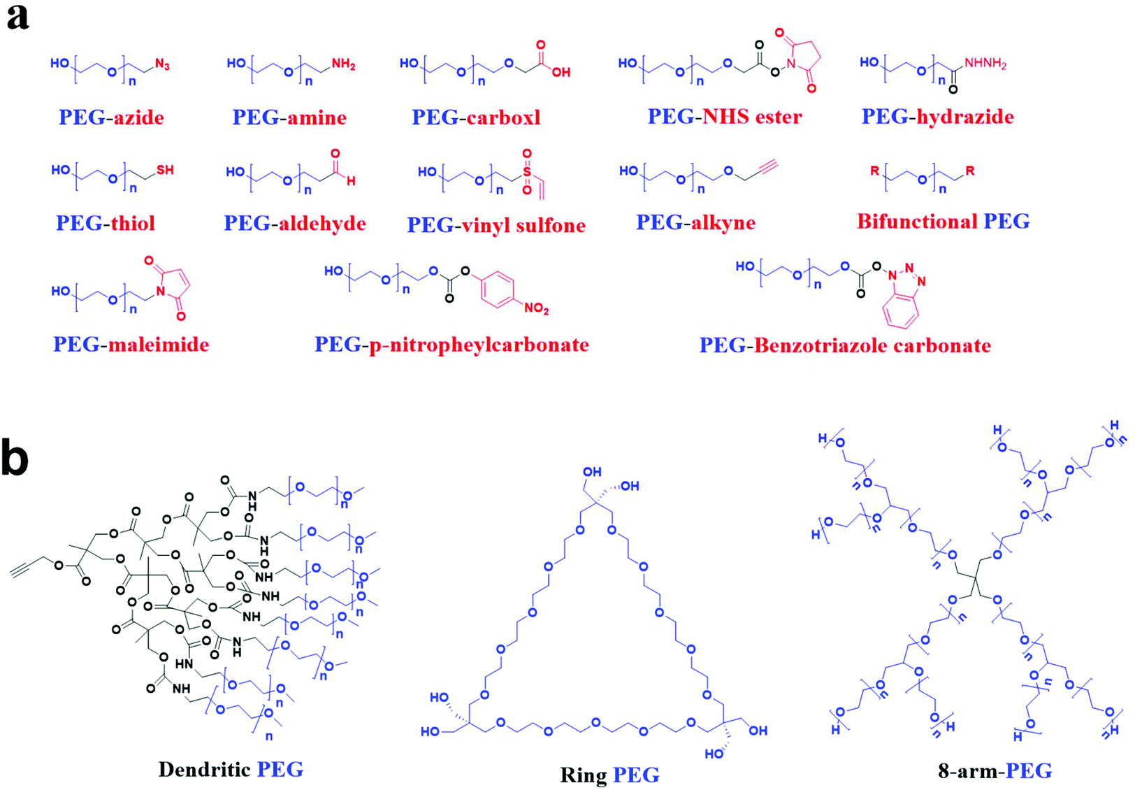 | ||
| Fig. 1 The structures of a variety of PEG molecules. (a) Linear PEG derivatives with functional terminal groups. (b) PEGs with nonlinear systems. Blue and red are the ethoxy units of PEG and functional groups, respectively. n denotes the degree of polymerization. | ||
Nanoparticles (NPs) have significant advantages such as small particle size, good stability, improving the insoluble drug's solubility, and reducing the drug toxicity.8,9 However, NPs that fail to reach the lesion site are removed by the mononuclear phagocytic system (MPS) through opsonization and activation of the complement system.10–12 Therefore, most stealth drug delivery systems’ research focuses on preventing NPs from being removed by the MPS in the body or utilizing the MPS function to inhibit inflammation and infection.13 So far, surface adsorption or grafting of the shielding group is widely used to prevent NPs from being removed by the MPS.14 Among the shielding groups, PEG is often selected for adsorption or grafting applications to surfaces of NPs due to its characteristics, including electrical neutrality, significant spatial repulsion, and high hydrophilicity.15,16
After PEGylation, a hydrophilic protective layer is formed around the NPs, which increases several times for the blood circulation half-life of the particles through spatial repulsion rejection.17,18 Also, it is easy for NPs to use PEG as a bridge to conjugate targeted ligands or peptides onto its hydroxy terminal, which can bind the corresponding over-expressed receptors on the surface of cells, to realize targeted drug delivery.19,20 PEG can improve the targeting delivery capability of NPs, inhibit the removal of NPs by the MPS, and tune some physicochemical properties of NPs, such as the mechanical properties of membranes, stability, and drug loading and release behavior. Molecular weight (MW) and PEG density are the key factors affecting the physicochemical and biological properties of NPs.1,21
The PEGylation degree of NPs can be flexibly changed by adjusting the experimental conditions and methods for preparing NPs. It is indispensable to precisely assess the coverage density and conformation of PEG on the surface of NPs using different equipment and techniques. Therefore, this review introduces the method of PEGylation and the available tools for quantitative evaluation of the coverage density and conformation of PEG on the surface of NPs and the advantages and limitations of each technology. Then, the basic properties of PEG, including MW, density, and conformation on the surface of NPs, are described to explain the effects on the biophysical and chemical properties of NPs.
2. PEGylation strategies for nanoparticles
PEG can significantly change the surface properties of the conjugated materials. Among these materials, most of their surfaces are hydrophobic and difficult to bind to PEG, resulting in low efficiency of conjugating PEG onto the surface of the materials.22 There are three typical coating strategies for PEG coating on the NP surface: (1) PEG physically adheres to NPs by physical adsorption, including electrostatic or hydrophobic interaction; (2) PEG is securely grafted onto the surface of NPs by forming a stable chemical bond; and (3) PEG can conjugate with hydrophobic molecules to form macromolecules that can self-assemble with themselves or other compounds to form PEGylated NPs in solution, as shown in Fig. 2.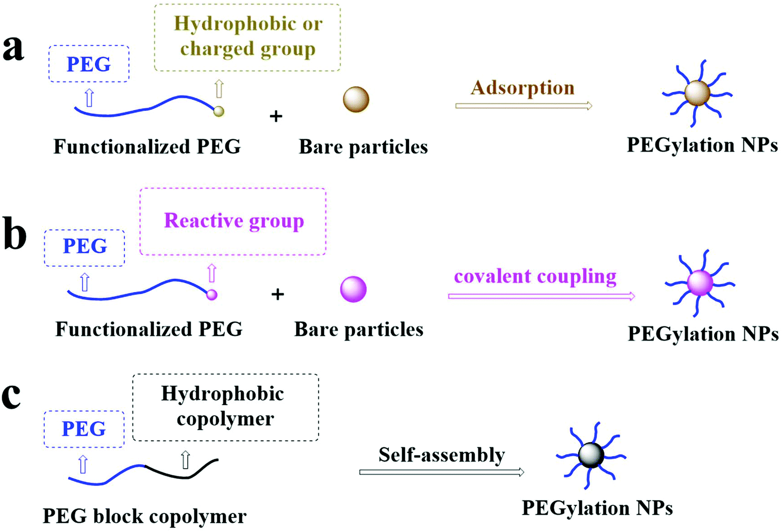 | ||
| Fig. 2 PEG is grafted onto the surface of NPs by (a) physical adsorption, (b) covalent coupling, and (c) copolymer self-assembly grafting of PEG to the surface of NPs. | ||
2.1. Physical absorption
Functionalization of the NP surface with PEG in a physical adsorption manner is the most traditional method with the advantage of simple operation and easily controlled conditions. The physical adsorption strategy is suitable if (1) the density of PEG or PEG derivatives on the substrate surface is not high and (2) there is a strong adsorption capability between PEG or PEG derivatives and substrates.22 The adsorption strategy absorbs the hydrophobic or charged groups with PEG based on hydrophobic interactions or electrostatic adsorption. For example, Shen et al. used the hydrophobic interaction between 1,2-distearyl-sn-glycero-3-phosphoethanolamine (DSPE) and 1,2-dioleoyl-sn-glycero-3-phosphoethanolamine (DOPE) to graft DOPE–PEG–NH2 onto the gold nanoparticle (GNP) surface with a covering of DSPE.23 Liu et al. used the electrostatic interaction between the cationic polymer polyethyleneimine (PEI) and the anion-containing heparan sulfate (HS) to graft PEG–PEI on the surface of the HS micelle.24 However, the physical adsorption strategy still faces serious problems such as low adsorption strength, leading to the separation of PEG chains from the NP surface under certain conditions.252.2. Chemical conjugation
NPs can be PEGylated by covalent coupling to avoid the separation of PEG from the NP surface. Still, it requires that the reaction between the exposed group on the substrate surface and PEG terminal groups can occur. So far, the responses of the covalent conjugate mainly include a Si–O bond formed by the reaction of mesoporous silica nanoparticles and PEG–silane,26 a Au–S bond formed by the response of Au and a –SH group,27 an amide bond formed by the response of the activated –COOH group and –NH2 group,28 thioester bonds formed by the reaction of activated PEG–COOH with a thiol group, a triazole group formed by azide–alkyne, or a thioether bond formed by thiol–alkene in a click reaction.29–31 This strategy's advantages include mild chemical reaction conditions, high yield, and stable enough chemical bonds between PEG and the modified substrate.22 PEG is only presented on the surface, which avoids the existence of PEG in the NP core.32 Therefore, the shelf-life of products after PEGylation is longer than those without PEG conjugation. This strategy's shortcoming is that the grafting effects are limited by the surface-active site's position and density. Therefore, it is difficult to ensure that the surface graft density can meet application requirements.33 On the other hand, because of the space hindrance and reaction rate differences, they may cause batch-to-batch variations in the graft ratio.342.3. Molecular self-assembly
The self-assembly of PEGylated NPs usually occurs through nanoprecipitation (also known as solvent diffusion) or emulsification (also known as solvent evaporation). Amphiphilic polymers (hydrophilic PEGs conjugated to hydrophobic polymers or lipids) are used to form spherical NPs by self-assembly with or without other compounds in water.35 The hydrophobic part of the polymer comprises the core of NPs, and the coating of PEG is the outer layer of particles. The researchers have also synthesized fluorescence-labeled polymers sensitive to light, enzymes, temperature, pH, ultrasound, or redox to prepare PEGylated NPs to improve drug delivery and bioimaging.36–43 The different copolymers are selected to prepare NPs with other functions and provide very high surface graft density under self-assembly strategies. However, the synthesis of these copolymers is relatively complex and requires precise operation and reasonable condition control.38 Also, studies have shown that the polymeric NPs prepared by emulsification have higher PEG coverage than those by nanoprecipitation.44,45 The emulsification process's disadvantage includes the damage of high shear force and energy requirements, which may cause harm to shear force- or heat-sensitive drugs and biological agents.463. Quantitative evaluation of surface PEG density
The physical and chemical properties of nanoparticles will be changed after PEG modification, such as hydrophilicity, hydrodynamic diameter, surface charge, and the feature of protein binding.47 The physical and chemical property changes are monitored to confirm the degree of PEGylation on the surface. For example, the diameter of NPs is slightly increased (from 253 to 286 nm). The surface charge is significantly reduced (from −30.1 to −18.6 mV) after grafting PEG on the surface of NPs loaded with itraconazole.48 These analyzing protocols only were the qualitative or semi-quantitative method to assess the extent of PEGylated modification. Still, they cannot be used to precisely measure PEG density on the surface of NPs.34 The following techniques are developed and optimized to obtain quantitative information of the degree of PEGylation on the NP surface.3.1. Detection of coordination complexes
Both I2/KI and Fe (SCN)3 can interact with PEG to produce colored compounds. The content of PEG was calculated by quantitative measurement of colored compounds by spectrophotometry.49,50 This method has advantages such as simple operation, low cost of equipment, and high sensitivity. However, the sensitivity decreases with the extension of detection time.51 Therefore, PEG can only be quantitatively detected in solution, which limits the applicability of this method.Enzymatic reactions can also be used to assess the coverage rate of surface PEG. Saltzman et al. fixed avidin onto palmitic acid within poly(lactide-co-glycolic acid) (PLGA) NPs to form a dense and stable avidin coating on the surface of the PLGA NPs, calculated the number of avidins per NP surface, and then grafted biotinylated PEG onto the surface of avidin-coated NPs whereas the uncoupled avidin on the surface of the same NPs was coated with biotinylated horseradish peroxidase (bHRP), as shown in Fig. 3. Finally, the bHRP signals of NPs were determined to calculate the surface PEG density. This method's limitation is that the spatial effects of a high MW PEG coating can effectively prevent bHRP from binding to avidin. PEG density may be higher than the actual value.52
 | ||
| Fig. 3 Avidin-NP surface covered with biotinylated PEG. Following PEG binding, biotinylated horseradish peroxidase (HRP) was used to probe the accessible surface PEG density. | ||
3.2. Thermogravimetric analysis
Thermogravimetric analysis (TGA), a precise thermal analysis method, can analyze the relationship between mass loss with a temperature increase of samples in a manner of program-controlled temperature.53 The essential characteristics of TGA are robust quantification with a wide detection range, which can be used to accurately measure the loss rate of substances.54 To detect the PEG density on the surface of GNPs, the percentage of weight loss of PEG, namely the degradation of PEG, is calculated in the temperature range of 302 to 450 °C. The binding level of PEG on the surface of GNPs can be measured by combining with isothermal titration calorimetry (ITC).55 The content of PEG on the surface of metal NPs measured by TGA may be underestimated due to the separation of the adsorbed PEG from the surface of NPs caused by multiple centrifugal steps to remove the unbound PEG.56 Therefore, TGA needs the data support of other analytical methods to detect the density of PEGs on the NP surface accurately.573.3. Ultraviolet and fluorescence spectra
PEG chains are coupled with a chromophore to label the surface of NPs. Chromatographic separation or ultracentrifugation methods are used to separate free PEG–chromophore or PEGylated NPs. The isolated substances will be detected by the subsequent ultraviolet (UV) or fluorescence signals. The PEG amount on the NP surface was calculated based on the established standard curve of PEG–chromophore.58,59 For PEG with an –NH2 terminal, the –NH2 group can be quantified using the Kaiser test. The Kaiser test is based on the reaction of the –NH2 group with ninhydrin to produce Ruhemann's purple, which shows ultraviolet absorption at 256 nm.60 The PEG coverage density is determined according to the established standard curve of reference standards.61 The sensitivity of the fluorophore-labeling detection method is much higher than that of the Kaiser test; it may because the random coil conformation of PEG often engulfs the available –NH2 groups and reduces their reactivity.62,63 The most common problem of chromophore-labeled PEG is that the physical and chemical properties change due to chromophore existence, which may affect the determination of the PEG density on the NP surface.343.4. Nuclear magnetic resonance
Nuclear magnetic resonance (NMR) is a robust quantitative analysis method. The chemical shift on the NMR spectrum reflects the chemical environment of the molecule skeleton. The peak area is proportional to the number of protons of the substance measured.64,65 NMR has undergone improvements in equipment and processing methods and can be used to determine PEG density on the surface of NPs.66,67 The potential problem with the NMR analytical method is that particle aggregation after freeze-drying results in a decrease of the analyzable surface, underestimating the surface of PEG. To avoid such issues, low-temperature preservatives (usual carbohydrates) are usually added. However, low-temperature preservatives may interfere with the internal standard of PEG, changing their NMR signals. This problem can also be solved by directly preparing NPs by emulsifying D2O containing hydrophilic internal standards.68 However, after NPs are dispersed in a deuterated solvent, it is difficult for NMR spectroscopy to distinguish the signal of PEG in the core of NPs. The call can be obtained only when PEG is grafted or adsorbed on the surface of NPs.69,703.5. X-ray photoelectron spectroscopy
X-ray photoelectron spectroscopy (XPS) is used to analyze the chemical composition of surfaces.71,72 X-rays irradiate PEG on the surface of NPs and trigger the emission of photoelectrons. The emitted photoelectrons are collected, and their energy is identified and quantified by detectors. These data can be converted into the percentage of surface composition to evaluate the coverage density of PEG.73,74There are several limitations for XPS quantifying PEG on particle surfaces: (1) so far, XPS measurement has to be carried out on a collapsed dehydrated PEG layer (in a vacuum). The drying process can affect the thickness and surface distribution of the PEG layer;73 (2) it is highly complicated to quantify PEG on a multi-component surface when the surface contains other ether compounds;75 (3) due to the limited electron penetration ability, the maximum sampling depth of carbon electrons is about 10 nm, and the maximum sampling depth of oxygen electrons is about 8 nm.76 Additionally, a combination of scanning transmission electron microscopy and energy-dispersive X-ray spectroscopy (STEM-EDS) is a great technique to scan the surface composition of materials. Elemental maps by STEM-EDS can precisely and sharply analyze the distribution of elements in the surface layer but not damage the samples.77
4. Conformation of the PEG chain
The conformation of the PEG chain on the surface of NPs is usually described according to the density of PEG, which is based on the Flory radius of PEG (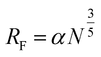 , where α is the length of the ethoxy unit (3.5 nm) and N is the extent of polymerization of PEG), the distance between two PEG grafting points (
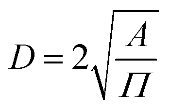 , where A is the area occupied by the PEG chain, and
  , where σ is the coverage-density of PEG and S is total NP surface in a sample), or the length/thickness of the grafted PEG layer (
 ). According to these parameters, PEG can exhibit two main conformations, namely, mushroom and brush conformations. The loose PEG coating has high elasticity if the surface density is low (D > 2RF), so that the PEG chains on the surface of NPs cannot be fully extended, thus forming a mushroom conformation, as shown in Fig. 4a. Upon increasing the grafting density (D < 2RF), the dense PEG coating exerts a high osmotic pressure in the medium, causing the curled PEG chains on the surface of the NPs to extend outward, thereby forming a brush conformation, as shown in Fig. 4b.34,78 When D < RF, a brush conformation is further defined as a dense brush by Damodaran, as shown in Fig. 4c.79 Jameson found no all-mushroom or all-brush conformation of PEG on the surface of NPs due to the density nonuniformity or distribution shifts of PEG on the NPs.80 There may exist multiple conformation types on a single NP. Moreover, mushroom and brush conformations are found in both low and high coverage densities of PEG. The difference between the two cases was that a more significant proportion of the brush conformation existed under a higher PEG coverage density.
 | ||
| Fig. 4 PEG conformations on a particle surface: (a) Mushroom conformation, (b) brush conformation, and (c) Dense brush conformation. FP: PEG footprint (projected area), APEG: area available to each PEG chain. FP = APEG in the brush regime, and APEG > FP in the mushroom regime. | ||
4.1. Effects of solvent on conformation changes
The influences of solvent on the PEG chain conformation are very significant. Selli et al. studied PEG chains’ conformation on the surface of TiO2 NPs in different solvents (water and dichloromethane) based on atomistic molecular dynamics simulations. Data indicated that PEG had a strong interaction with water molecules compared with dichloromethane. The transformation from a mushroom conformation to a brush conformation in water started only at a high density (2.25 chains per nm2). It has become a brush conformation in dichloromethane due to the presence of more OPEG–Ti bonds between the terminal group of PEG and Ti atoms (2.25 chains per nm2). Finally, the brush conformation of PEG in water, not in dichloromethane, follows the Daoud–Cotton classic scaling model, which has been described as a star-shaped polymer system.814.2. Effects of the molecular weight of PEG on conformation changes
The MW of PEG affects NP PEGylation.82,83 Lu et al. found that the diffusion rate of free HS–PEG in water decayed exponentially with an increase of MW, resulting in an increased PEG density on the surface of NPs as its MW decreases.66 Rabanel, Chan, and Teramura also observed a similar phenomenon caused by the excluded volume effects.84–865. Effects of surface PEG on nanoparticle fate
Although different PEGylation technologies and methods used to detect the basic properties of the PEG layer on the surface of NPs, including MW, density, and conformation, have been reported, the effects of the basic properties of the PEG layer on the physicochemical properties of NPs need a further study. The following mainly reviewed the impact of PEG MW, density, and conformation on the biophysical and chemical properties of NPs, as shown in Fig. 5.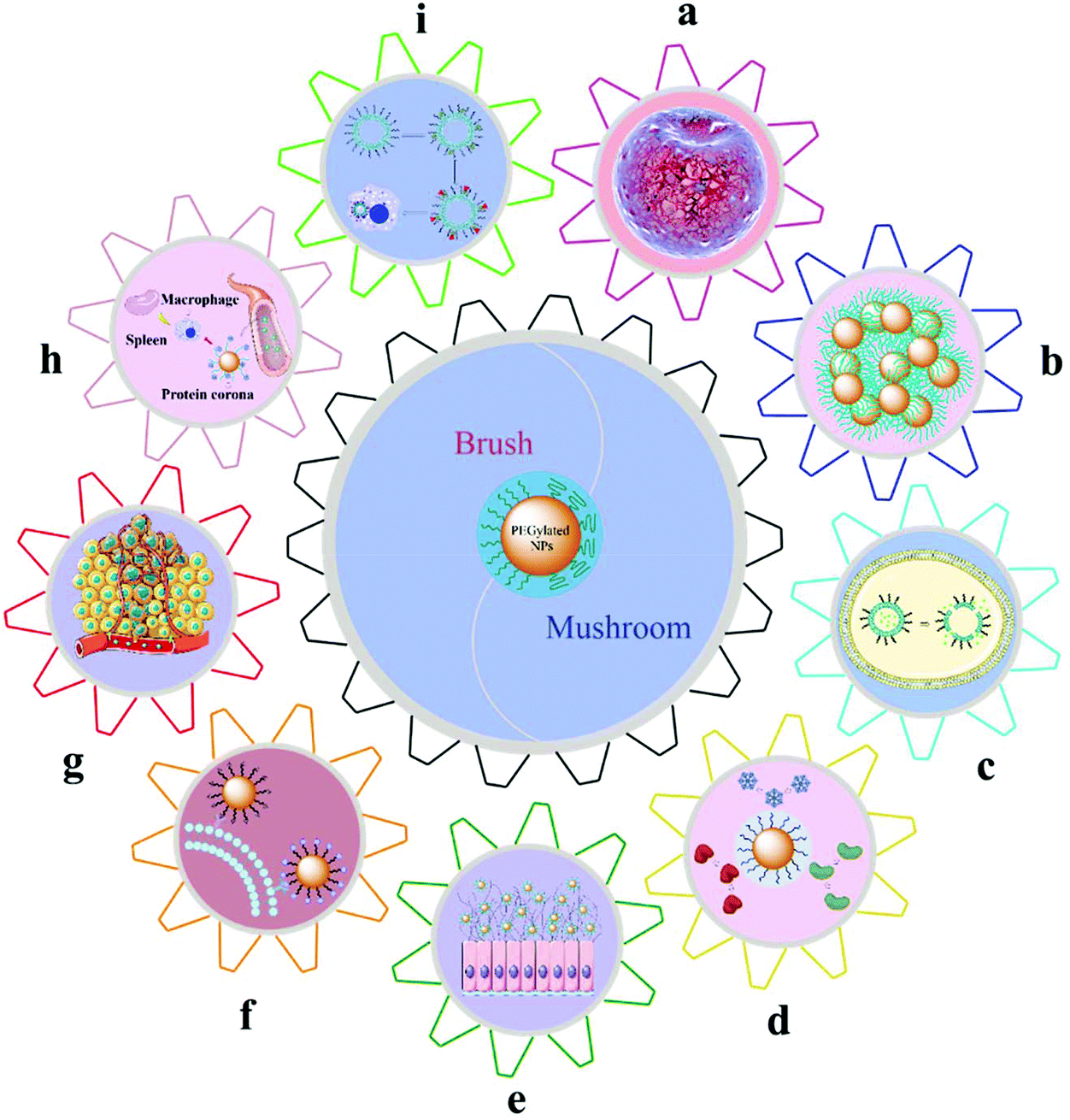 | ||
| Fig. 5 The effects of surface PEG on the nanoparticle fate: (a) Film mechanical properties, (b) nanoparticle stability, (c) drug encapsulation and release behavior, (d) nonspecific adsorption of plasma proteins, (e) mucus penetration, (f) selectivity of active targeting, (g) cellular internalization, (h) circulation time in vivo, and (i) accelerated blood clearance effects. | ||
5.1. Film mechanical feature
Mechanical features are involved in the response of a material to stress, such as elasticity and stiffness. Elasticity is the ability of materials to endure the distortion rendered by pressure and recover their original shape after relief, including compressibility modulus and bending modulus. Stiffness is the resistance of materials to elastic deformation or deflection. The opposite direction of stiffness is flexibility due to the shape changes of underused material pressure. In recent years, the influences of PEG on the mechanical properties of materials have been widely studied. For example, Alexander and Gennes predicted that the lipid bilayer membrane's stiffness increased with the increase of the MW and graft density of PEG in the brush conformation based on the scaling theory of polymer brushes.87,88 Also, Mahendra et al. found that the increase in the mole fraction of DSPE–PEG increased the repulsion force between two neighbor PEG chains that increased the bending modulus in the lipid bilayer membrane. This phenomenon would be more evident in PEG with a higher MW.895.2. Nanoparticle stability
PEG on the surface of NPs is responsible for colloidal stability through steric repulsion. This steric repulsion is more evident for PEG with a higher MW.90–93 The reason is that the distance between two NPs increases with the increase of the length of PEG chains, thus enhancing the steric repulsion of PEG and avoiding the aggregation of NPs.94 Indeed, the thickness of the PEG layer is regulated by the MW and the coverage degree of PEG on the particles simultaneously. Lin et al. found that if the coverage degree of PEG on the GNP surface was 40% (1.10 chains per nm2), the nanoparticles were stably dispersed in water by avoiding close contact when the distance reached 7.5 nm (the extent of polymerization of PEG was four or bigger).95 GNPs with different sizes require different amounts of PEG to achieve colloidal stability. Quach et al. found that the incubation rate of PEG: GNPs (PEG per particle surface) was 1000 to maintain the colloidal stability of PEGylated GNPs with a particle size of 10 nm. For PEGylated GNPs with particle sizes of 20, 40, and 80 nm, the incubation rates were 5000, 25![[thin space (1/6-em)]](https://www.rsc.org/images/entities/char_2009.gif) 000, and 125000, respectively.96 Additionally, some data have confirmed that increasing the density of PEG on the non-viral gene fragment loaded nanoparticles can improve the stability of particles in the physiological saline but decrease the delivery efficiency of particles.97–100
000, and 125000, respectively.96 Additionally, some data have confirmed that increasing the density of PEG on the non-viral gene fragment loaded nanoparticles can improve the stability of particles in the physiological saline but decrease the delivery efficiency of particles.97–100
5.3. Drug encapsulation and release behavior
Most NPs with a core–shell structure are often loaded with functional molecules, such as anti-cancer drugs and fluorescent agents to kill cancer cells or realize fluorescence imaging.101 Therefore, the encapsulation efficiency (the number of active molecules loaded) plays an extremely vital role in the quality of NPs. The PEG in NPs often affects the encapsulation efficiency of loaded molecules. As the PEG–lipid mole fraction increases, the membrane's permeability increases, making the encapsulated drug leak unfavorable for drug delivery.102–104 The encapsulation efficiency of water-soluble drugs decreases with the increase of the PEG-containing lipid content and the MW of PEG. The possible reason is that PEG will occupy the volume of NPs, and the bigger the MW of PEG, the more the volume is taken.105,106 The method used to solve this problem is the introduction of PEG into the pre-formed NPs so that PEG is grafted on the surface of the NPs instead of in the core of those, reducing the volume of the body occupied by PEG.107 For hydrophobic drugs encapsulated in the micelle core by hydrophobic interaction, the maximum drug loading capacity increases significantly with the increase of the MW of PEG. The reason might be that the hydrophilic shell formed by long-chain PEG prevents drug desorption from the micelle core.108On the other hand, the way of drug release has a significant impact on the therapeutic effect of NPs. The ideal way of drug release is to reduce the administration frequency and ensure a stable, sustained release. PEG in the core forms the water channel, which can be a favorite to the diffusion and release of drugs. The number of water channels is positively proportional to the content of PEG. As a result, the initial release of the drug increases with an increase in the PEG content.109 Micelles composed of PEGylated cationic block copolymers have PEGs with different MWs or a low PEG content on their surface to reduce the electrostatic interaction between the block copolymer and siRNA, the intracellular siRNA release being more effective.110,111 Moreover, PEGylated chitosan NPs whose PEGs with many more MWs have a greater degree of substitution so that NPs can release drugs faster.112
5.4. Nonspecific adsorption of plasma proteins
Non-specific adsorption of plasma proteins is the most influential factor deciding the fate of NPs. The high resistance of protein adsorption can reduce the uptake, degradation, and elimination rate of NPs by the MPS, thus prolonging the half-life of NPs in blood.113 The zeta potential (ζ) on the surface of NPs is another crucial factor for the adsorption of plasma proteins.114 The increase of MW and density of PEG on the NP surface will increase the PEG layer thickness, which results in an ζ value closely being neutral and improving the anti-protein adsorption capacity of NPs.115–118The flexibility of PEG refers to the degree of free rotation of the skeleton around the ether bond and describes the free movement of the molecular structure in solution. Higher PEG movement will create a more significant space barrier between NPs and proteins, which prevents proteins from approaching the surface of NPs.119 However, the flexibility of PEG on the surface of liposomes is challenging to evaluate through experimental analysis. Therefore, the influences of PEG flexibility on liposome stability are mainly discussed and assessed based on computer simulations.120 Abe et al. found that PEG with a small MW had strong intra-molecular interactions, less flexibility, and weak anti-protein adsorption capability. However, PEG with a sizeable MW was more flexible and robust anti-protein absorption capability due to the formation of a large hydration shell.121 Walkey et al. reported the opposite phenomenon that as the grafting density of PEG increased, the flexibility of PEG decreases non-linearly, resulting in a decrease in the hydrodynamic volume of PEG and an increase of the anti-protein adsorption capability.122
Long-chain PEG provides more potent effects of steric hindrance than short-chain PEG, such as reducing the electrostatic or van der Waals force between the surface of NPs and the protein, thereby restricting the protein to a greater distance from the NPs, as shown in Fig. 6a.123 Also, the effects of steric hindrance of anti-protein adsorption depend on the conformation of PEG, which is usually achieved in the brush conformation at a high coverage density, as shown in Fig. 6b.122 This may be because the PEG coating with a dense brush conformation has a thicker hydrophilic barrier, while the PEG coating with a lower density mushroom conformation has a thinner hydrophobic barrier.124 However, results from Zhou's group supported that the dynamic density of the outer PEG layer on the surface of PLGA NPs slightly lowered the mushroom-brush transition state, which reduced the binding affinity between protein and NPs. Meanwhile, the uptake by sinusoidal endothelial cells (SECs) within liver tissue was also reduced due to the dynamic topographical structure of NPs.125
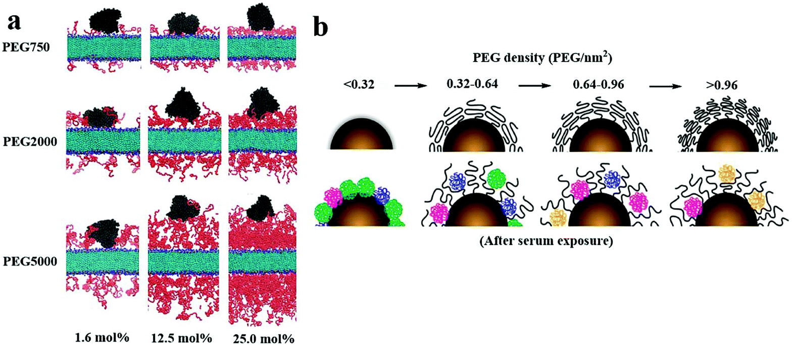 | ||
| Fig. 6 (a) When coated with PEG with a low graft density (1.6 mol%), human serum albumins (HSAs) were able to introduce into the layer of PEG and combine with the double layer with three PEGs (750, 2000, and 5000 Da); when coated with PEG with a medium graft density (12.5 mol%), HSAs were able to contact with the double layer grafted with PEGs with a MW of 750 Da, but not with those with a MW of 2000 or 5000 Da; when coated with PEG with a high graft density (25 mol%), HSAs were not able to contact with the double layer grafted with any PEGs (750, 2000, and 5000 Da), indicating that the density and MW of the PEG layer hinder the combination of HSAs and double-layer surface. Red and black refer to PEGs and HSAs, respectively; light blue and blue represent the lipid bilayer. PEG concentrations were 1.6, 12.5, and 25 mol%. (b) PEG with a brush conformation at a high coverage density reduced the plasma protein adsorption. This figure has been adapted/reproduced from ref. 122 and 123 with permission from ACS, copyright 2012 and 2016. | ||
The MW and density of PEG on the surface of NPs are two interrelated standards, which can compensate each other to create an optimal effect for protein rejection. It should be noted that (1) the optimal PEG density for protein rejection depends mainly on the particle size and surface curvature;126 (2) NPs also have weak resistance of protein adsorption at the low PEG coverage density, whereas PEG coating cannot wholly prevent protein adsorption at the high PEG coverage density;78,127 (3) the size and electrostatic properties of plasma proteins affect the degree of protein adsorption.128 Therefore, we should pay more attention to the influences of particle size, surface curvature, and some plasma proteins on the PEG layer of anti-protein adsorption.
5.5. Mucus penetration
The mucous layer on the mucosal surface effectively traps traditional nanoparticles through spatial interactions and adhesion to each other, thereby preventing their even distribution.129,130 Entanglement between PEG and mucoprotein makes particles challenging to penetrate the mucus layer, as shown in Fig. 7a.131 Nevertheless, many researchers continue to investigate whether the PEG coating can effectively prevent mucoprotein from interacting with NPs through the precise adjustments of the PEG graft density and MW.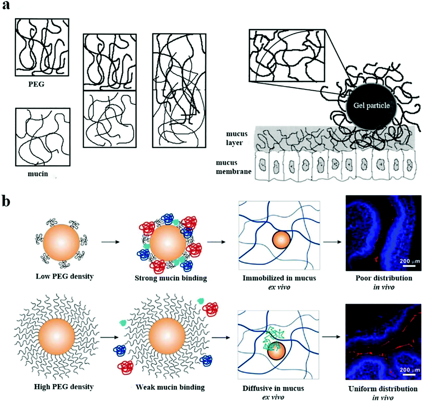 | ||
| Fig. 7 (a) The mechanism of PEG/mucin interpenetration leading to nanoparticle entanglement and stickiness is explained. This figure has been adapted/reproduced from ref. 44 with permission from ACS, copyright 2015. (b) The surfaces of the nanoparticles with mushroom conformational PEG were not fully protected and they interacted with the mucin in the mucus layer, resulting in the nanoparticles being fixed in the mucus and poorly distributed on the mucosal surface. The PEG with the brush conformation effectively protected the nanoparticles from mucin binding, improving the diffusion and distribution of the nanoparticles. This figure has been adapted/reproduced from ref. 131 with permission from Elsevier, copyright 2000. | ||
Wang et al. found that the interaction between the PEG chain and the mucus was minimal when about 40% of the –COOH groups on the polystyrene surface of NPs conjugated with PEG with a MW of 2 kDa. The hydrogen-bonding and electrostatic interaction between PEG and glycosylated mucoprotein resulted in minimal adhesion.132 In another coarse-grained molecular dynamics simulation, it was found that the status of PEG was changed from the mushroom conformation to a brush conformation when the PEG density on the surface of NPs increased to 6%, leading to the most significant capability of NPs to penetrate mucus.133 A recent study demonstrated a relationship between the ratio of RF to D (RF/D) and the ability of NPs to bind to mucoprotein. Given that RF/D < 2, the surface of NPs would be firmly adhered to the mucoprotein, while RF/D ≥ 2.4, the absorption of the mucus component would be avoided. This was because the effective diffusion rate of NPs in mucus slightly decreased when the parameter of the surface PEG density, RF/D, was ≥2.4 compared with RF/D < 2.44 According to the RF/D formula, the increase of the MW of PEG will help the polymer to form a dense brush conformation, which further increases the mucus inertness of the PEG coating. Conte et al. found that increasing the MW of PEG was able to change the surface PEG of NPs to form a brush conformation and promote the penetration of NPs through the mucus layer.134 However, the high MW of PEG on the surface of NPs is not conducive to penetrate the mucosa. Zabaleta and Huang et al. found that PEG with a MW of 2 kDa with a brush conformation promoted their diffusion in the mucus layer. When the MW of PEG was increased to 10 kDa, the interaction between PEG and mucoproteins was increased, blocking the diffusion and distribution of NPs in the mucus layer.135,136 It is worth noting that the sufficient MW and density of the PEG on the surface of NPs make PEG change to a brush conformation so that particles can more easily contact the mucus and enhance the penetration of NPs on the mucosal surface, as shown in Fig. 7b.44
The PEG coating has potential disadvantages for enhancement of mucus diffusion: (1) anti-PEG antibody has been detected in mucus;137 (2) enhancing the penetration and distribution of NPs in mucus does not directly lead to the increased cellular uptake.130 To overcome these PEG limitations, an N-(2-hydroxypropyl) methacrylamide copolymer (pHPMA) has been selected as a substitute.138
5.6. Selectivity of active targeting
To improve the endocytosis of PEGylated NPs, the PEG on the surface is usually bound to ligands. The interaction of specific ligands and cell surface receptors can overcome the spatial obstruction between PEG and cell membranes, thereby enhancing the internalization of PEGylated NPs into cells. However, PEG can interfere with ligand recognition.139–141 The possible reason is as follows: when the MW of the PEG-linker is large, the increased flexibility of the PEG chain causes the entanglement of PEG chains to reduce the binding of the ligand to the receptor. In contrast, given that the surface PEG-linker density is minimal, the mushroom conformation PEG-linker makes the ligand mainly distributed in the hydrophilic shell, thereby reducing the opportunities of ligand–receptor coupling on the surface of the cellular membrane, as shown in Fig. 8a and b.142 However, Fukuda et al. found that when the PEG-linker density was 0.75 chain per nm2, the ligand's recognition efficiency reached the maximum. When the PEG-linker density was 1 chain per nm2, the coupling ability of the ligand was significantly reduced.143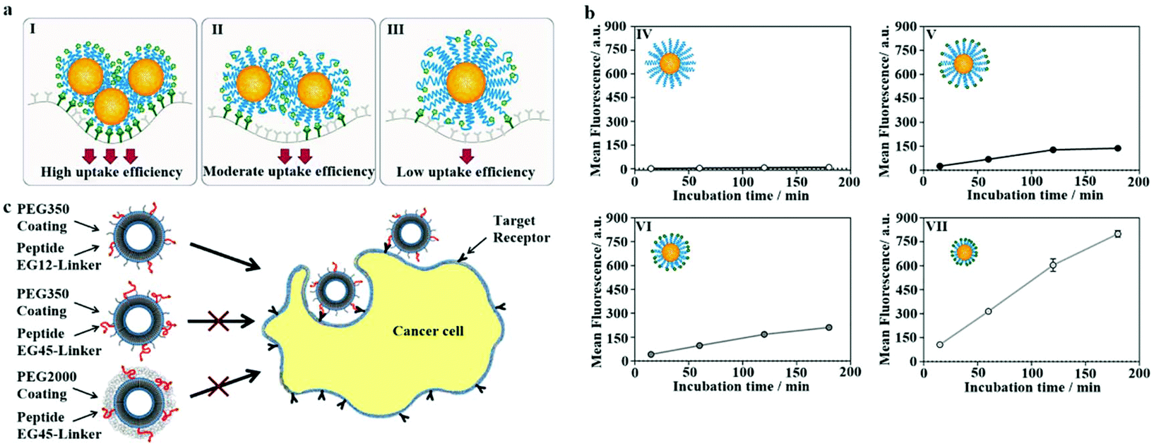 | ||
| Fig. 8 (a) The PEG-linker's molecular weight (MW) was larger; the PEG chain's increased flexibility caused the entanglement of the PEG chains, thereby reducing the interaction opportunity of the ligand and receptor. Blue = PEG, green = RGD, dark green = αvβ3, yellow = NPs. (b) Coupling kinetics of (IV) NPs containing cRGD0–PEG5k, (V) NPs containing cRGD100–PEG5k, (VI) NPs containing cRGD100–PEG3.5k, and (VII) NPs containing cRGD100–PEG2k. The glioma cells (U87MG) were treated with NPs for 15, 60, 120, or 180 minutes. Flow cytometry to detect cell-associated fluorescence. This figure has been adapted/reproduced from ref. 142 with permission from ACS, copyright 2019. (c) Adjust the PEG coating and PEG layer thickness linking agent's length to overcome the space shielding problem caused by the shorter PEG linking agent being immersed in the longer PEG coating layer. This figure has been adapted/reproduced from ref. 146 with permission from ACS, copyright 2013. | ||
Therefore, the mixed PEG chains with different molecular weights are proposed to improve the properties of NPs. For example, Jia et al. modified SiO2 NPs with PEG with a MW of 3 kDa as the linker of Arg–Gly–Asp (RGD) peptides, and then the PEG MW of 2 kDa was mixed to improve the targeting and stealth properties of particles.144 However, when the PEG-linker length is shorter than the PEG coating's thickness, the ligands may be shielded by the longer PEG without targeting ligands.145 Therefore, researchers try to adjust the PEG-linker's MW and PEG cover layer to overcome the problems mentioned above. Dai and Du used medium-affinity small-molecule peptides as targeting ligands and found that when PEG-linker's MW was greater than that of the PEG coating, the peptides extended beyond the PEG coating to effectively bind to the corresponding receptors, as shown in Fig. 8c.146 The accumulation of the smallest lipid nanoparticles (size: 35 nm) containing PEG–phospholipid in the liver was the highest compared to those of other bigger particles (size: 80 and 45 nm). The weak gene silencing of particles with the smallest size could be improved by adding N-acetylgalactosamine cluster conjugated PEG–DSG (GalNAc–PEG).147 Anisamide, a ligand to the sigma receptor, can be conjugated onto the terminal end of PEG on the surface of the nanoparticles to target the prostate cancer tissue, which is an overexpressed sigma receptor.148 The targeted delivery of folate-modified nanoemulsion-contained aclacinomycin A (FNEA) to cancer cells can be regulated by the chain length of PEGs and percentage of the folate–PEG linker in the formulations.149
5.7. Cellular internalization
In the process of drug delivery mediated by PEGylated NPs, one of the most critical steps is the internalization of NPs by cells, namely endocytosis. Molecular dynamics simulation provides a calculating method for detailing the atomic level's cell internalization process. Jameson and Oroskar used molecular dynamics simulations to understand the effects of PEG on the internalization of NPs by cells. They found that with the increase of the MW and coverage density of PEG on the GNP surface, the number of NPs internalized by cells increased. The brush conformation of PEG with a high MW more easily destroys the membrane, resulting in a longer internalization time.80,150However, for targeted NPs with PEG as a linker, increasing the MW of PEG leads to decreased cell internalization, which thermodynamic methods can elucidate. When NPs interact with cell membranes, four main determining factors determine the free energy of the system
| Fs = Fm + Fcs + Fl + Fp. | (1) |
In this equation, Fm refers to the cell membrane's bending energy, which is associated with changes in the cell membrane's bending rate during the internal swallowing of NPs. Fcs describes the changes in the distortion energy of the cytoskeleton. Fl represents the energy of interaction between the ligand and the receptor, and Fp is the free energy produced by spatial rejection between the PEG chain and the cell membrane.151Fl decreases when the mating-subject binds. During NP internalization, Fm, Fcs, and Fp increased. According to formula (1), if the increase of Fm, Fcs, and Fp is less than the decrease of Fl, endocytosis will be triggered. The entanglement of PEG chains with a high MW and the reduction of ligand–receptor binding events lead to Fl. Moreover, there was a significant increase of Fp in PEG with a high MW. Finally, the rise of Fm, Fcs, and Fp is greater than the decrease of Fl, and endocytosis will not be triggered, and cell internalization will decrease.142
5.8. Circulation time in vivo
The hydrophilic shell of PEG helps NPs avoid the uptake of the MPS and prolongs the circulation time of NPs in the body, which is usually called the stealth effect. Since the MW of PEG is directly related to the length of the PEG chain, the MW of PEG is one of the critical factors determining the stealth effect. Wang et al. found that NPs modified with PEG with a MW of 5 kDa have a longer circulation time.152 However, a long PEG chain easily causes the aggregation or destruction of liposomes. When the MW of PEG is greater than 5 kDa, the circulation time will decrease instead.153Moreover, NPs modified simultaneously with two MW PEGs may have a longer cycle time. Nissinen et al. found that a short PEG chain with a MW of 0.5 kDa and a long PEG chain with a MW of 2 kDa were coated on the NPs with a very dense PEG coating surface, which reduced the uptake of macrophages and increased the half-life of the NPs from 1 to 241 minutes.154 Haynes et al. also observed a similar phenomenon that liposomes simultaneously composed of DSPE–PEG with MWs of 1 kDa and 2 kDa showed longer circulation times in vivo.59
On the other hand, the stealth effects of NPs are closely related to the PEG density and conformation on particle surfaces.73 Studies have shown that the brush conformation of the PEG coating can effectively inhibit the uptake of macrophages and significantly increase the systemic circulation time of NPs, as shown in Fig. 9.140 For a long PEG chain with a MW of 10 kDa, to obtain maximum macrophage uptake inhibition, PEG with a dense brush conformation on the surface (RF/D > 8) is needed.155 However, Perry et al. confirmed that PEG with a MW of 5 kDa on the surface of hydrogel NPs exhibited a mushroom conformation (RF/D ∼ 0.9) or brush (RF/D ∼ 1.5), both of which can lead to a decrease in the macrophage uptake, especially the brush conformation. This inconsistency can be attributed to the presence of PEG in the inside of the NPs and the soft mechanical structure of the hydrogel NPs.78
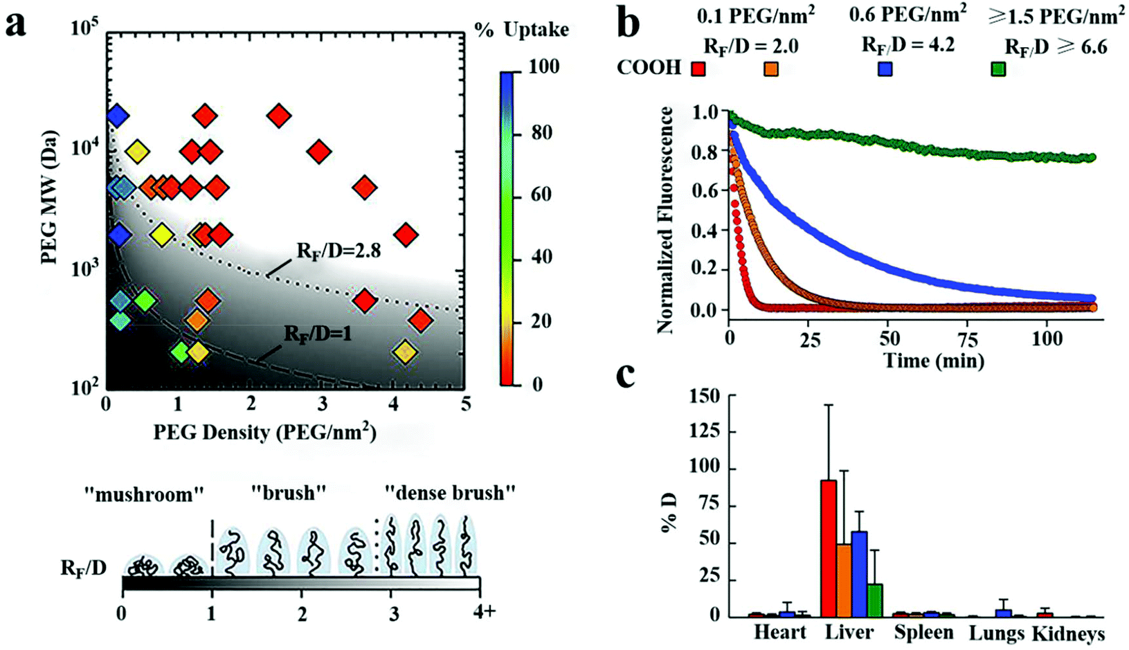 | ||
| Fig. 9 The effects of the surface PEG density on the internalization of polystyrene NPs by macrophages in vitro and half-life time of particles in blood vessels of mice. (a) A phase diagram of the internalization of NPs by human THP-1 differentiated cells affected by the coating density and MW of PEG. In vitro, high-density brushes of the NP surface were most valid in inhibiting macrophage internalization. (b) The number of NPs decorated with PEG molecules at different densities circulated in mice's blood vessels over time monitored with a live microscope. (c) The biodistribution of various NP preparations at 2 hours after intravenous injection. An increase in the surface density of PEG led to a decrease in PEG in the liver. This figure has been adapted/reproduced from ref. 140 with permission from Elsevier, copyright 2016. | ||
It is worth noting that RF/D ≥ 2.8 seems to be very suitable for NPs covered with PEG with a MW of 1–5 kDa. Still, longer PEG chains (10 kDa) require a more prominent RF/D. Therefore, long-chain PEG or suitable spatial conformation PEG should be selected according to the structural characteristics of NPs when NPs were prepared with a long circulation time.
5.9. Accelerated blood clearance effect
The accelerated blood clearance (ABC) phenomenon is that the circulating half-life of PEGylated nanoparticles is significantly shortened after particles being once again injected into the body, as shown in Fig. 10. This phenomenon was initially found in PEGylated liposomes,156 and it has been confirmed in many animals and a variety of PEGylated nanoparticles.157–162 ABC is considered to be the result of the occurrence of anti-PEG IgM in the spleen.163,164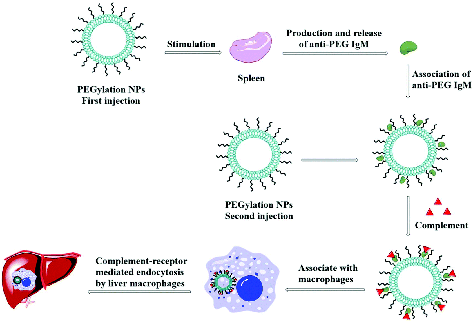 | ||
| Fig. 10 Schematic presents the procedural events after injection of PEGylated NPs responsible for accelerated blood clearance (ABC) effects. In this process, the spleen, after the first injection of PEGylated NPs, produces and releases anti-PEG antibodies. When these antibodies meet PEG on the surface of NPs again, they will adhere onto PEG chains, activating the complement system. The activated complements then associate with anti-PEG antibodies, enhancing the uptake via the complement-receptor mediated pathway. | ||
PEGylated liposomes may trigger anti-PEG IgM responses without the involvement of T-cells when PEG may be an epitope. It was reported that low-density PEG (<5 mol%) is not enough to activate spleen B cells, while too high a concentration of PEG (>5 mol%) causes the reduced reactivity of spleen B cells. Therefore, liposomes containing 5 mol% PEG monomethyl ether (mPEG) with a MW of 2 kDa can significantly drive the most considerable ABC effect in mice.165 The opposite was observed by Zhao and Pannuzzo, whose studies showed that NPs containing 5 mol% PEG had the least ability to cause the ABC effect. The former explanation was that NPs containing 5 mol% PEG had less effective contact with spleen B cells, leading to the least secretion of anti-PEG IgM, while the latter reason was that NPs containing 5 mol% PEG were more prominent in size and could adsorb IgM for not activating the classic pathway.166,167 Li et al. also found that although the two liposomes have similar anti-PEG IgM levels after the first administration, liposomes containing 9 mol% PEG could induce more severe ABC phenomena than liposomes containing 3 mol% PEG due to their higher affinity with anti-PEG IgM.168
On the other hand, Ishida et al. found that both PEG (2 kDa)–DSPE and PEG (5 kDa)–DSPE modified liposomes produced significant ABC phenomena after being injected into rats. However, when mice were used to perform the same experiments, PEG (5 kDa)–DSPE modified liposomes could induce the ABC phenomenon far less than PEG (2 kDa)–DSPE modified vesicles.169 A Beagle dog with a more sensitive immune system than mice was selected as an experimental animal to investigate the inconsistency due to species-specific differences. The results showed that PEG molecules with larger molecular weights were entangled to form a dense network structure, making plasma esterases difficult to attack carbonate bonds and alleviating the ABC phenomenon.170 The spatial conformation formed by an emulsion with small MW PEG was more likely to stimulate splenic B cells, resulting in strong ABC effects.171 Liu et al. found a similar phenomenon and interpreted that more antigen epitopes (–(CH2CH2O)–subunits) of PEG with a high MW (5 kDa) combined with B cells to result in B cell anergy, which means the inability of the B cells to produce PEG antibodies and to induce complement activation mediated by antibodies.172 However, Su et al. held that PEG with a MW of 5 kDa caused the most substantial ABC effects than other PEGs with different molecular weights (350 Da, 550 Da, 10 kDa, and 20 kDa). The reason may be that micelles modified with PEG with a MW of 5 kDa have a longer circulation time in vivo after firstly being injected, which leads to more opportunities for PEG with a MW of 5 kDa to stimulate B cells to produce anti-PEG IgM.173
Although PEGylated NPs can prolong the half-life time of drugs in blood and reduce the immunogenicity of conjugated proteins and drug carriers, the ABC phenomenon limits the development of PEGylation of NPs. The strategy to reduce or eliminate the immunogenicity of PEGylated NPs without affecting their performance in vivo is urgently needed for the translation of a promising drug delivery system. Fortunately, after long-term efforts, researchers have developed some strategies to avoid the ABC effects, for example, (1) choosing a lower immunogenic branched chain PEG instead of linear PEG or OH–PEG instead of mPEG174–177 and (2) injecting long-chain PEG before the administration of PEGylated drugs to saturate immune complexes.178
6. Limitations and improvement strategy
So far, the development of PEGylated nano-drug carriers has not reached the expected results, and the main reasons are as follows: (1) the reported surface PEG density of NPs is an average value without any relevant standard deviation or interval; (2) also, although total PEG can be quantified, PEG on the surface or in the core of NPs cannot be precisely quantified;134 (3) technology lack of complete characterization of NPs; (4) the incomplete understanding of tissue biology and biological barriers, which control the interaction between nano-drug carriers and the surface of host cells or the matrix;179,180 and (5) PEG modification can extend the cycle life of particles, and also limit the ability of NPs to transport gene fragments to the nucleus or cytoplasm of tumor cells.181 Finally, the ligand modification further makes the analysis of PEG conformation more complicated.Some measures need to be taken to solve these problems: (1) Improvement of the equipment feature for measuring the PEG density on the NP surface, to optimize and standardize existing methods;182 (2) further study of the relationship between the MW, the surface density of PEG, and the biophysical and chemical characteristics of NPs; (3) looking for non-toxic, biocompatible polymers to replace PEG;183–188 (4) further evaluate the effectiveness and safety of the clinical application of invisible NPs; and (5) there is no doubt about the benefits of PEGylation of NPs and how to control PEGylation.189 Finally, the effects of ligand conjugation on the PEG status of the actively targeted NP surface are still not clear. Clarifying the complicated reasons for the changes related to the conformation of the PEG chain on the NPs has a long way to go.
Conflicts of interest
There are no conflicts to declare.Acknowledgements
Dr Peng thanks the National Natural Science Foundation of China for supporting this work (No. 81671814), the Heilongjiang Provincial Natural Science Foundation (No. ZD2016013), the Wu Liande Youth Scientific Research Fund of Harbin Medical University-Daqing (JFWLD202002), the Scientific Research Fund of Harbin Medical University-Daqing (2018XN-22, 2018XN-24, JFXN201902, and JFXN201908), and the Guiding project of Science and Technology from the Science and Technology Bureau of Daqing City (zdy-2019-87 and zdy-2019-88). Dr Wang acknowledges the PhRMA Foundation Research Starter Award (No. RSGTMT17).References
- C. Sanchez-Cano and M. Carril, Int. J. Mol. Sci., 2020, 21, 2–24 CrossRef PubMed.
- K. Rahme and N. Dagher, Pharmaceutics, 2019, 11, 2–23 CrossRef PubMed.
- B. Yu, Y. Yang, Q. Liu, A. Zhan, Y. Yang and H. Liu, Pharmaceutics, 2020, 12, 2–13 Search PubMed.
- H. J. Hsu, Y. Han, M. Cheong, P. Kral and S. Hong, Nanomedicine, 2018, 14, 1879–1889 CrossRef CAS PubMed.
- K. Kinbara, Polym. J., 2018, 50, 689–697 CrossRef CAS.
- M. Barz, R. Luxenhofer, R. Zentel and M. J. Vicent, Polym. Chem., 2011, 2, 1900–1918 RSC.
- T. Wu, K. Chen, S. He, X. Liu, X. Zheng and Z.-X. Jiang, Org. Process Res. Dev., 2020, 24, 1364–1372 CrossRef CAS.
- G. Chen, Y. Wang, R. Xie and S. Gong, Adv. Drug Delivery Rev., 2018, 130, 58–72 CrossRef CAS PubMed.
- S. Peng, B. Ouyang, Y. Men, Y. Du, Y. Cao, R. Xie, Z. Pang, S. Shen and W. Yang, Biomaterials, 2020, 231, 119680 CrossRef CAS PubMed.
- V. P. Vu, G. B. Gifford, F. Chen, H. Benasutti, G. Wang, E. V. Groman, R. Scheinman, L. Saba, S. M. Moghimi and D. Simberg, Nat. Nanotechnol., 2019, 14, 260–268 CrossRef CAS PubMed.
- F. Zahednezhad, M. Saadat, H. Valizadeh, P. Zakeri-Milani and B. Baradaran, J. Controlled Release, 2019, 305, 194–209 CrossRef CAS PubMed.
- S. M. Moghimi, D. Simberg, E. Papini and Z. S. Farhangrazi, Adv. Drug Delivery Rev., 2020, 157, 83–95 CrossRef CAS PubMed.
- X. Hou, X. Zhang, W. Zhao, C. Zeng, B. Deng, D. W. McComb, S. Du, C. Zhang, W. Li and Y. Dong, Nat. Nanotechnol., 2020, 15, 41–46 CrossRef CAS PubMed.
- D. E. Owens 3rd and N. A. Peppas, Int. J. Pharm., 2006, 307, 93–102 CrossRef PubMed.
- A. A. D′souza and R. Shegokar, Expert Opin. Drug Delivery, 2016, 13, 1257–1275 CrossRef PubMed.
- J. V. Jokerst, T. Lobovkina, R. N. Zare and S. S. Gambhir, Nanomedicine, 2011, 6, 715–728 CrossRef CAS PubMed.
- T. U. Wani, S. N. Raza and N. A. Khan, Polym. Bull., 2019, 77, 3865–3889 CrossRef.
- Kenry, T. Yeo, P. N. Manghnani, E. Middha, Y. Pan, H. Chen, C. T. Lim and B. Liu, ACS Nano, 2020, 14, 4509–4522 CrossRef CAS PubMed.
- Y. L. Lo, C. H. Chang, C. S. Wang, M. H. Yang, A. M. Lin, C. J. Hong and W. H. Tseng, Theranostics, 2020, 10, 6695–6714 CrossRef CAS PubMed.
- Y. Huang, Z. Xue and S. Zeng, ACS Appl. Mater. Interfaces, 2020, 12, 31172–31181 CrossRef CAS PubMed.
- S. Y. Fam, C. F. Chee, C. Y. Yong, K. L. Ho, A. R. Mariatulqabtiah and W. S. Tan, Nanomaterials, 2020, 10, 2–18 CrossRef PubMed.
- X.-F. Xiao, X.-Q. Jiang and L.-J. Zhou, Chin. J. Anal. Chem., 2013, 41, 445–453 CrossRef CAS.
- Z. Shen, D. T. Loe, A. Fisher, M. Kroger, J. L. Rouge and Y. Li, Nanoscale, 2019, 11, 20179–20193 RSC.
- Y. Liu, T. Lang, Z. Zheng, H. Cheng, X. Huang, G. Wang, Q. Yin and Y. Li, Small, 2019, 15, 1902822 CrossRef CAS PubMed.
- H. Kaur, T. Das, R. Kumar, R. Ajore and L. M. Bharadwaj, BioSystems, 2008, 92, 69–75 CrossRef CAS PubMed.
- Q. He, J. Zhang, J. Shi, Z. Zhu, L. Zhang, W. Bu, L. Guo and Y. Chen, Biomaterials, 2010, 31, 1085–1092 CrossRef CAS PubMed.
- B. Yin, C. K. W. Chan, S. Liu, H. Hong, S. H. D. Wong, L. K. C. Lee, L. W. C. Ho, L. Zhang, K. C. Leung, P. C. Choi, L. Bian, X. Y. Tian, M. N. Chan and C. H. J. Choi, ACS Nano, 2019, 13, 14048–14069 CrossRef CAS PubMed.
- C. A. Cheng, W. Chen, L. Zhang, H. H. Wu and J. I. Zink, J. Am. Chem. Soc., 2019, 141, 17670–17684 CrossRef CAS PubMed.
- M. Matsumoto, M. Matsusaki and M. Akashi, Macromol. Biosci., 2014, 14, 142–150 CrossRef CAS PubMed.
- H. Huang, M. Liu, X. Tuo, J. Chen, L. Mao, Y. Wen, J. Tian, N. Zhou, X. Zhang and Y. Wei, Appl. Surf. Sci., 2018, 439, 1143–1151 CrossRef CAS.
- R. Jiang, M. Liu, T. Chen, H. Huang, Q. Huang, J. Tian, Y. Wen, Q.-Y. Cao, X. Zhang and Y. Wei, Dyes Pigm., 2018, 148, 52–60 CrossRef CAS.
- S. Shi, C. Yao, J. Cen, L. Li, G. Liu, J. Hu and S. Liu, Angew. Chem., 2020, 59, 18172–18178 CrossRef CAS PubMed.
- B. H. C. Tami, L. Lasseter, N. L. Abbott and R. J. Hamers, J. Am. Chem. Soc., 2004, 126, 10220–10221 CrossRef PubMed.
- J. M. Rabanel, P. Hildgen and X. Banquy, J. Controlled Release, 2014, 185, 71–87 CrossRef CAS PubMed.
- X. Liu, X. Shen, X. Sun, Y. Peng, R. Li, P. Yun, C. Li, L. Liu, F. Su and S. Li, Polym. Adv. Technol., 2018, 29, 205–215 CrossRef CAS.
- J. W. Hindley, Y. Elani, C. M. McGilvery, S. Ali, C. L. Bevan, R. V. Law and O. Ces, Nat. Commun., 2018, 9, 1093 CrossRef PubMed.
- C.-C. Cheng, J.-J. Huang, A.-W. Lee, S.-Y. Huang, C.-Y. Huang and J.-Y. Lai, ACS Appl. Bio Mater., 2019, 2, 2162–2170 CrossRef CAS.
- K. Porte, B. Renoux, E. Peraudeau, J. Clarhaut, B. Eddhif, P. Poinot, E. Gravel, E. Doris, A. Wijkhuisen, D. Audisio, S. Papot and F. Taran, Angew. Chem., Int. Ed., 2019, 58, 6366–6370 CrossRef CAS PubMed.
- N. Pandey, J. U. Menon, M. Takahashi, J. T. Hsieh, J. Yang, K. T. Nguyen and A. S. Wadajkar, Nanotheranostics, 2020, 4, 1–13 CrossRef PubMed.
- J. Song, L. Lin, Z. Yang, R. Zhu, Z. Zhou, Z.-W. Li, F. Wang, J. Chen, H. Yang and X. Chen, J. Am. Chem. Soc., 2019, 141, 8158–8170 CAS.
- C. H. Fan, T. W. Wang, Y. K. Hsieh, C. F. Wang, Z. Gao, A. Kim, Y. Nagasaki and C. K. Yeh, ACS Appl. Mater. Interfaces, 2019, 11, 11144–11156 CrossRef CAS PubMed.
- J. Wang, D. Li, W. Tao, Y. Lu, X. Yang and J. Wang, Biomacromolecules, 2019, 20, 1740–1747 CrossRef CAS PubMed.
- Y. Zhou, H. Gao, F. Zhu, M. Ge and G. Liang, J. Hazard. Mater., 2019, 368, 630–637 CrossRef CAS PubMed.
- Q. Xu, L. M. Ensign, N. J. Boylan, A. Schon, X. Gong, J. C. Yang, N. W. Lamb, S. Cai, T. Yu, E. Freire and J. Hanes, ACS Nano, 2015, 9, 9217–9227 CrossRef CAS PubMed.
- J. Hrkach, D. Von Hoff, M. Mukkaram Ali, E. Andrianova, J. Auer, T. Campbell, D. De Witt, M. Figa, M. Figueiredo, A. Horhota, S. Low, K. McDonnell, E. Peeke, B. Retnarajan, A. Sabnis, E. Schnipper, J. J. Song, Y. H. Song, J. Summa, D. Tompsett, G. Troiano, T. Van Geen Hoven, J. Wright, P. LoRusso, P. W. Kantoff, N. H. Bander, C. Sweeney, O. C. Farokhzad, R. Langer and S. Zale, Sci. Transl. Med., 2012, 4, 128–139 Search PubMed.
- F. G. Rohit Karnik, P. Basto, C. Cannizzaro, L. Dean, W. Kyei-Manu, R. Langer and O. C. Farokhzad, Nano Lett., 2008, 8, 2906–2912 CrossRef PubMed.
- J. Simon, T. Wolf, K. Klein, K. Landfester, F. R. Wurm and V. Mailander, Angew. Chem., Int. Ed., 2018, 57, 5548–5553 CrossRef CAS PubMed.
- R. Machado Cruz, M. J. Santos-Martinez and L. Tajber, Eur. J. Pharm. Biopharm., 2019, 144, 57–67 CrossRef CAS PubMed.
- S. M. D'Addio, W. Saad, S. M. Ansell, J. J. Squiers, D. H. Adamson, M. Herrera-Alonso, A. R. Wohl, T. R. Hoye, C. W. Macosko, L. D. Mayer, C. Vauthier and R. K. Prud'homme, J. Controlled Release, 2012, 162, 208–217 CrossRef PubMed.
- A. Nag, G. Mitra and P. C. Ghosh, Anal. Biochem., 1996, 237, 224–231 CrossRef CAS PubMed.
- T.-L. Cheng, K.-H. Chuang, B.-M. Chen and S. R. Roffler, Bioconjugate Chem., 2012, 23, 881–899 CrossRef CAS PubMed.
- Y. Cu and W. M. Saltzman, Mol. Pharm., 2009, 6, 173–181 CrossRef CAS PubMed.
- A. A. Dongargaonkar and J. D. Clogston, Methods Mol. Biol., 2018, 1682, 57–63 CrossRef CAS PubMed.
- S. Vyazovkin, Macromol. Rapid Commun., 2019, 40, 1–15 CrossRef PubMed.
- W. Wang, Q. Q. Wei, J. Wang, B. C. Wang, S. H. Zhang and Z. Yuan, J. Colloid Interface Sci., 2013, 404, 223–229 CrossRef CAS PubMed.
- D. K. Joanne Manson, B. J. Meenan and D. Dixon, Gold Bull., 2011, 44, 99–105 CrossRef.
- K. B. Sebby and E. Mansfield, Anal. Bioanal. Chem., 2015, 407, 2913–2922 CrossRef CAS PubMed.
- C. Pereira Gomes, V. Leiro, C. D. Ferreira Lopes, A. P. Spencer and A. P. Pêgo, Acta Biomater., 2018, 78, 247–259 CrossRef CAS PubMed.
- M. T. Haynes and L. Huang, ACS Appl. Mater. Interfaces, 2016, 8, 24361–24377 CrossRef CAS PubMed.
- E. Kaiser, R. L. Colescott, C. D. Bossinger and P. I. Cook, Anal. Biochem., 1970, 34, 595–598 CrossRef CAS PubMed.
- X. Xia, M. Yang, Y. Wang, Y. Zheng, Q. Li, J. Chen and Y. Xia, ACS Nano, 2012, 6, 512–522 CrossRef CAS PubMed.
- B. Ahmad, M. A. Ansari, P. Sen and R. H. Khan, Biopolymers, 2006, 81, 350–359 CrossRef CAS PubMed.
- S. Bar-Chaput and C. Carrot, J. Appl. Polym. Sci., 2006, 100, 3490–3497 CrossRef CAS.
- J. Vi Cha, J. Novotny, S. Komorovsky, M. Straka, M. Kaupp and R. Marek, Chem. Rev., 2020, 105, 7065–7103 CrossRef PubMed.
- S. Nerli, A. C. McShan and N. G. Sgourakis, Prog. Nucl. Magn. Reson. Spectrosc., 2018, 106–107, 1–25 CrossRef CAS PubMed.
- J. Lu, Y. Xue, R. Shi, J. Kang, C. Y. Zhao, N. N. Zhang, C. Y. Wang, Z. Y. Lu and K. Liu, Chem. Sci., 2019, 10, 2067–2074 RSC.
- M. Retout, E. Brunetti, H. Valkenier and G. Bruylants, J. Colloid Interface Sci., 2019, 557, 807–815 CrossRef CAS PubMed.
- Q. Xu, N. J. Boylan, S. Cai, B. Miao, H. Patel and J. Hanes, J. Controlled Release, 2013, 170, 279–286 CrossRef CAS PubMed.
- E. A. Nance, G. F. Woodworth, K. A. Sailor, T. Y. Shih, Q. Xu, G. Swaminathan, D. Xiang, C. Eberhart and J. Hanes, Sci. Transl. Med., 2012, 4, 149ra119 Search PubMed.
- M. F. Ebbesen, B. Whitehead, B. Ballarin-Gonzalez, P. Kingshott and K. A. Howard, Pharm. Res., 2013, 30, 1758–1767 CrossRef CAS.
- G. Greczynski and L. Hultman, Angew. Chem., 2020, 59, 5002–5006 CrossRef CAS PubMed.
- A. M. Abdel-Mageed, A. Klyushin, A. Rezvani, A. Knop-Gericke, R. Schlogl and R. J. Behm, Angew. Chem., Int. Ed., 2019, 58, 10325–10329 CrossRef CAS PubMed.
- J. M. Rabanel, J. Faivre, S. F. Tehrani, A. Lalloz, P. Hildgen and X. Banquy, ACS Appl. Mater. Interfaces, 2015, 7, 10374–10385 CrossRef CAS PubMed.
- B. Pelaz, P. del Pino, P. Maffre, R. Hartmann, M. Gallego, S. Rivera-Fernandez, J. M. de la Fuente, G. U. Nienhaus and W. J. Parak, ACS Nano, 2015, 9, 6996–7008 CrossRef CAS PubMed.
- A. Brindley, S. S. Davis, M. C. Davies and J. F. Watts, J. Colloid Interface Sci., 1995, 171, 150–161 CrossRef CAS.
- S. Tanuma, C. J. Powell and D. R. Penn, Surf. Interface Anal., 1994, 165–176 CrossRef CAS.
- S. Wenner, L. Jones, C. D. Marioara and R. Holmestad, Micron, 2017, 96, 103–111 CrossRef CAS PubMed.
- J. L. Perry, K. G. Reuter, M. P. Kai, K. P. Herlihy, S. W. Jones, J. C. Luft, M. Napier, J. E. Bear and J. M. DeSimone, Nano Lett., 2012, 12, 5304–5310 CrossRef CAS PubMed.
- V. B. Damodaran, C. J. Fee, T. Ruckh and K. C. Popat, Langmuir, 2010, 26, 7299–7306 CrossRef CAS PubMed.
- C. J. Jameson, P. Oroskar, B. Song, H. Yuan and S. Murad, Biomimetic Lipid Membranes: Fundamentals, Applications, and Commercialization, 2019, pp. 109–165 Search PubMed.
- D. Selli, S. Motta and C. Di Valentin, J. Colloid Interface Sci., 2019, 555, 519–531 CrossRef CAS PubMed.
- H. Zhang, W. Wang, M. Akinc, S. Mallapragada, A. Travesset and D. Vaknin, Nanoscale, 2017, 9, 8710–8715 RSC.
- H. Zhang, W. Wang, S. Mallapragada, A. Travesset and D. Vaknin, Nanoscale, 2017, 9, 164–171 RSC.
- J. M. Rabanel, V. Adibnia, S. F. Tehrani, S. Sanche, P. Hildgen, X. Banquy and C. Ramassamy, Nanoscale, 2019, 11, 383–406 RSC.
- C. H. Chan, F. Poignant, M. Beuve, E. Dumont and D. Loffreda, J. Phys. Chem. Lett., 2020, 11, 2717–2723 CrossRef CAS PubMed.
- Y. Teramura, K. Kuroyama and M. Takai, Acta Biomater., 2016, 30, 135–143 CrossRef CAS PubMed.
- P. G. de Gennes and T. A. Witten, Phys. Today, 1980, 33, 51–54 CrossRef.
- S. Alexander, J. Phys., 1977, 38, 983–987 CrossRef CAS.
- A. Mahendra, H. P. James and S. Jadhav, Chem. Phys. Lipids, 2019, 218, 47–56 CrossRef CAS PubMed.
- M. A. Jackson, T. A. Werfel, E. J. Curvino, F. Yu, T. E. Kavanaugh, S. M. Sarett, M. D. Dockery, K. V. Kilchrist, A. N. Jackson, T. D. Giorgio and C. L. Duvall, ACS Nano, 2017, 11, 5680–5696 CrossRef CAS PubMed.
- B. M. Godinho, J. R. Ogier, A. Quinlan, R. Darcy, B. T. Griffin, J. F. Cryan and C. M. O'Driscoll, Int. J. Pharm., 2014, 473, 105–112 CrossRef CAS PubMed.
- A. R. Jochem, G. N. Ankah, L. A. Meyer, S. Elsenberg, C. Johann and T. Kraus, Anal. Chem., 2016, 88, 10065–10073 CrossRef CAS PubMed.
- S. F. Tehrani, F. Bernard-Patrzynski, I. Puscas, G. Leclair, P. Hildgen and V. G. Roullin, Nanomedicine, 2019, 16, 185–194 CrossRef CAS.
- Y. Jiang, T. P. Lodge and T. M. Reineke, J. Am. Chem. Soc., 2018, 140, 11101–11111 CrossRef CAS.
- J. Lin, H. Zhang, V. Morovati and R. Dargazany, J. Colloid Interface Sci., 2017, 504, 325–333 CrossRef CAS PubMed.
- Q. H. Quach, R. L. X. Kong and J. C. Y. Kah, Bioconjugate Chem., 2018, 29, 976–981 CrossRef CAS PubMed.
- B. Li, X. Luo, B. Deng, J. Wang, D. W. McComb, Y. Shi, K. M. Gaensler, X. Tan, A. L. Dunn, B. A. Kerlin and Y. Dong, Nano Lett., 2015, 15, 8099–8107 CrossRef CAS PubMed.
- H. Otsuka, Y. Nagasaki and K. Kataoka, Adv. Drug Delivery Rev., 2003, 55, 403–419 CrossRef CAS.
- S. Mishra, P. Webster and M. E. Davis, Eur. J. Cell Biol., 2004, 83, 97–111 CrossRef CAS PubMed.
- X. Zhang, W. Zhao, G. N. Nguyen, C. Zhang, C. Zeng, J. Yan, S. Du, X. Hou, W. Li, J. Jiang, B. Deng, D. W. McComb, R. Dorkin, A. Shah, L. Barrera, F. Gregoire, M. Singh, D. Chen, D. E. Sabatino and Y. Dong, Sci. Adv., 2020, 6, eabc2315 CrossRef CAS PubMed.
- M. Chu, H. Li, Q. Wu, F. Wo and D. Shi, Biomaterials, 2014, 35, 8357–8373 CrossRef CAS.
- K. Hashizaki, H. Taguchi, C. Itoh, H. Sakai, M. Abe, Y. Saito and N. Ogawa, Chem. Pharm. Bull., 2005, 53, 27–31 CrossRef CAS PubMed.
- K. Edwards and M. Almgren, Langmuir, 1992, 8, 824–832 CrossRef CAS.
- A. R. Nicholas, M. J. Scott, N. I. Kennedy and M. N. Jones, Biochim. Biophys. Acta, 2000, 1463, 167–178 CrossRef CAS.
- V. De Leo, S. Ruscigno, A. Trapani, S. Di Gioia, F. Milano, D. Mandracchia, R. Comparelli, S. Castellani, A. Agostiano, G. Trapani, L. Catucci and M. Conese, Int. J. Pharm., 2018, 545, 378–388 CrossRef CAS.
- T. T. Lin, D. Y. Gao, Y. C. Liu, Y. C. Sung, D. Wan, J. Y. Liu, T. Chiang, L. Wang and Y. Chen, J. Controlled Release, 2016, 221, 62–70 CrossRef CAS PubMed.
- P. S. Uster, T. M. Allen, B. E. Daniel, C. J. Mendez, M. S. Newman and G. Z. Zhu, FEBS Lett., 1996, 386, 243–246 CrossRef CAS PubMed.
- Z. Pan, D. Fang, N. Song, Y. Song, M. Ding, J. Li, F. Luo, H. Tan and Q. Fu, ACS Appl. Mater. Interfaces, 2017, 9, 2138–2149 CrossRef CAS PubMed.
- A. K. Chandel, C. U. Kumar and S. K. Jewrajka, ACS Appl. Mater. Interfaces, 2016, 8, 3182–3192 CrossRef CAS.
- M. Miteva, K. C. Kirkbride, K. V. Kilchrist, T. A. Werfel, H. Li, C. E. Nelson, M. K. Gupta, T. D. Giorgio and C. L. Duvall, Biomaterials, 2015, 38, 97–107 CrossRef CAS.
- A. Lechanteur, T. Furst, B. Evrard, P. Delvenne, P. Hubert and G. Piel, Eur. J. Pharm. Sci., 2016, 93, 493–503 CrossRef CAS PubMed.
- S. A. Papadimitriou, D. S. Achilias and D. N. Bikiaris, Int. J. Pharm., 2012, 430, 318–327 CrossRef CAS PubMed.
- A. E. Nel, L. Madler, D. Velegol, T. Xia, E. M. Hoek, P. Somasundaran, F. Klaessig, V. Castranova and M. Thompson, Nat. Mater., 2009, 8, 543–557 CrossRef CAS PubMed.
- H. Devalapally, F. Zhou, J. McDade, G. Goloverda, A. Owen, I. J. Hidalgo and S. Silchenko, Drug Delivery, 2015, 22, 467–474 CrossRef CAS PubMed.
- S. P. Balguri, G. R. Adelli, K. Y. Janga, P. Bhagav and S. Majumdar, Int. J. Pharm., 2017, 529, 32–43 CrossRef CAS PubMed.
- J. M. Williford, M. M. Archang, I. Minn, Y. Ren, M. Wo, J. Vandermark, P. B. Fisher, M. G. Pomper and H. Q. Mao, ACS Biomater. Sci. Eng., 2016, 2, 567–578 CrossRef CAS.
- M. Uz, V. Bulmus and S. Alsoy Altinkaya, Langmuir, 2016, 32, 5997–6009 CrossRef CAS PubMed.
- J. G. Dancy, A. S. Wadajkar, C. S. Schneider, J. R. H. Mauban, O. G. Goloubeva, G. F. Woodworth, J. A. Winkles and A. J. Kim, J. Controlled Release, 2016, 238, 139–148 CrossRef CAS PubMed.
- V. S. T. Vladimir and P. Torchilin, Adv. Drug Delivery Rev., 1995, 16, 141–155 CrossRef.
- V. P. Torchilin, V. G. Omelyanenko, M. I. Papisov, A. A. Bogdanov, V. S. Trubetskoy, J. N. Herron and C. A. Gentry, Biochim. Biophys. Acta, Biomembr., 1994, 1195, 11–20 CrossRef CAS.
- K. Abe, K. Higashi, K. Watabe, A. Kobayashi, W. Limwikrant, K. Yamamoto and K. Moribe, Colloids Surf., A, 2015, 474, 63–70 CrossRef CAS.
- C. D. Walkey, J. B. Olsen, H. Guo, A. Emili and W. C. Chan, J. Am. Chem. Soc., 2012, 134, 2139–2147 CrossRef CAS.
- H. Lee and R. G. Larson, Biomacromolecules, 2016, 17, 1757–1765 CrossRef CAS PubMed.
- H. I. Labouta, M. J. Gomez-Garcia, C. D. Sarsons, T. Nguyen, J. Kennard, W. Ngo, K. Terefe, N. Iragorri, P. Lai, K. D. Rinker and D. T. Cramb, RSC Adv., 2018, 8, 7697–7708 RSC.
- H. Zhou, Z. Fan, P. Y. Li, J. Deng, D. C. Arhontoulis, C. Y. Li, W. B. Bowne and H. Cheng, ACS Nano, 2018, 12, 10130–10141 CrossRef CAS PubMed.
- K. Partikel, R. Korte, N. C. Stein, D. Mulac, F. C. Herrmann, H. U. Humpf and K. Langer, Eur. J. Pharm. Biopharm., 2019, 141, 70–80 CrossRef CAS PubMed.
- C. V. Maria Teresa Peracchia, C. Passirani, P. Couvreur and D. Labarre, Life Sci., 1997, 61, 749–761 CrossRef.
- S. Pasche, J. Vörös, H. J. Griesser, N. D. Spencer and M. Textor, J. Phys. Chem. B, 2005, 109, 17545–17552 CrossRef CAS PubMed.
- J. T. Huckaby, C. L. Parker, T. M. Jacobs, A. Schaefer, D. Wadsworth, A. Nguyen, A. Wang, J. Newby and S. K. Lai, Angew. Chem., Int. Ed., 2019, 58, 5604–5608 CrossRef CAS PubMed.
- J. T. Huckaby and S. K. Lai, Adv. Drug Delivery Rev., 2018, 124, 125–139 CrossRef CAS PubMed.
- Y. Huang, W. Leobandung, A. Foss and N. A. Peppas, J. Controlled Release, 2000, 65, 63–71 CrossRef CAS.
- Y.-Y. Wang, S. K. Lai, J. S. Suk, A. Pace, R. Cone and J. Hanes, Angew. Chem., Int. Ed., 2008, 47, 9726–9729 CrossRef CAS.
- Y. Yang, F. Tian, D. Nie, Y. Liu, K. Qian, M. Yu, A. Wang, Y. Zhang, X. Shi and Y. Gan, Sci. Adv., 2020, 6, eaay9937 CrossRef CAS PubMed.
- C. Conte, G. Dal Poggetto, B. J. Swartzwelter, D. Esposito, F. Ungaro, P. Laurienzo, D. Boraschi and F. Quaglia, Nanomaterials, 2019, 9, 1354 CrossRef CAS.
- V. Zabaleta, G. Ponchel, H. Salman, M. Agueros, C. Vauthier and J. M. Irache, Eur. J. Pharm. Biopharm., 2012, 81, 514–523 CrossRef CAS.
- X. Huang, J. Chisholm, J. Zhuang, Y. Xiao, G. Duncan, X. Chen, J. S. Suk and J. Hanes, Proc. Natl. Acad. Sci. U. S. A., 2017, 114, E6595–E6602 CrossRef CAS.
- C. E. Henry, Y. Y. Wang, Q. Yang, T. Hoang, S. Chattopadhyay, T. Hoen, L. M. Ensign, K. L. Nunn, H. Schroeder, J. McCallen, T. Moench, R. Cone, S. R. Roffler and S. K. Lai, Acta Biomater., 2016, 43, 61–70 CrossRef CAS.
- W. Shan, X. Zhu, M. Liu, L. Li, J. Zhong, W. Sun, Z. Zhang and Y. Huang, ACS Nano, 2015, 9, 2345–2356 CrossRef CAS PubMed.
- Z. Su, J. Niu, Y. Xiao, Q. Ping, M. Sun, A. Huang, W. You, X. Sang and D. Yuan, Mol. Pharm., 2011, 8, 1641–1651 CrossRef CAS.
- J. S. Suk, Q. Xu, N. Kim, J. Hanes and L. M. Ensign, Adv. Drug Delivery Rev., 2016, 99, 28–51 CrossRef CAS PubMed.
- M. G. YuJun Wang, C. Y. Gong, C. Wang, Z. Y. Qian, Y. F. Lin and F. Luo, Curr. Drug Metab., 2012, 13, 338–353 CrossRef PubMed.
- K. Abstiens, M. Gregoritza and A. M. Goepferich, ACS Appl. Mater. Interfaces, 2019, 11, 1311–1320 CrossRef CAS.
- I. Fukuda, S. Mochizuki and K. Sakurai, Colloids Surf., B, 2016, 146, 642–658 CrossRef CAS.
- T. Jia, J. Ciccione, T. Jacquet, M. Maurel, T. Montheil, A. Mehdi, J. Martinez, B. Eymin, G. Subra and J. L. Coll, Int. J. Pharm., 2019, 568, 118507 CrossRef CAS.
- S. Wang and E. E. Dormidontova, Biomacromolecules, 2010, 11, 1785–1813 CrossRef CAS PubMed.
- J. F. Stefanick, J. D. Ashley, T. Kiziltepe and B. Bilgicer, ACS Nano, 2013, 7, 2935–2947 CrossRef CAS PubMed.
- S. Chen, Y. Y. Tam, P. J. Lin, A. K. Leung, Y. K. Tam and P. R. Cullis, J. Controlled Release, 2014, 196, 106–112 CrossRef CAS.
- K. A. Fitzgerald, M. Malhotra, M. Gooding, F. Sallas, J. C. Evans, R. Darcy and C. M. O'Driscoll, Int. J. Pharm., 2016, 499, 131–145 CrossRef CAS.
- Y. Ohguchi, K. Kawano, Y. Hattori and Y. Maitani, J. Drug Targeting, 2008, 16, 660–667 CrossRef CAS PubMed.
- P. A. Oroskar, C. J. Jameson and S. Murad, Langmuir, 2016, 32, 7541–7555 CrossRef CAS PubMed.
- Y. Li, M. Kroger and W. K. Liu, Biomaterials, 2014, 35, 8467–8478 CrossRef CAS PubMed.
- J. L. Wang, X. J. Du, J. X. Yang, S. Shen, H. J. Li, Y. L. Luo, S. Iqbal, C. F. Xu, X. D. Ye, J. Cao and J. Wang, Biomaterials, 2018, 182, 104–113 CrossRef CAS PubMed.
- H. Ren, Y. He, J. Liang, Z. Cheng, M. Zhang, Y. Zhu, C. Hong, J. Qin, X. Xu and J. Wang, ACS Appl. Mater. Interfaces, 2019, 11, 20304–20315 CrossRef CAS.
- T. Nissinen, S. Nakki, H. Laakso, D. Kuciauskas, A. Kaupinis, M. I. Kettunen, T. Liimatainen, M. Hyvonen, M. Valius, O. Grohn and V. P. Lehto, ACS Appl. Mater. Interfaces, 2016, 8, 32723–32731 CrossRef CAS PubMed.
- Q. Yang, S. W. Jones, C. L. Parker, W. C. Zamboni, J. E. Bear and S. K. Lai, Mol. Pharm., 2014, 11, 1250–1258 CrossRef CAS PubMed.
- M. Mohamed, A. S. Abu Lila, T. Shimizu, E. Alaaeldin, A. Hussein, H. A. Sarhan, J. Szebeni and T. Ishida, Sci. Technol. Adv. Mater., 2019, 20, 710–724 CrossRef CAS PubMed.
- G. T. Kozma, T. Meszaros, I. Vashegyi, T. Fulop, E. Orfi, L. Dezsi, L. Rosivall, Y. Bavli, R. Urbanics, T. E. Mollnes, Y. Barenholz and J. Szebeni, ACS Nano, 2019, 13, 9315–9324 CrossRef CAS PubMed.
- M. D. McSweeney, T. Wessler, L. S. L. Price, E. C. Ciociola, L. B. Herity, J. A. Piscitelli, W. C. Zamboni, M. G. Forest, Y. Cao and S. K. Lai, J. Controlled Release, 2018, 284, 171–178 CrossRef CAS.
- H. Xu, F. Ye, M. Hu, P. Yin, W. Zhang, Y. Li, X. Yu and Y. Deng, Drug Delivery, 2015, 22, 598–607 CrossRef CAS.
- T. Ishihara, M. Takeda, H. Sakamoto, A. Kimoto, C. Kobayashi, N. Takasaki, K. Yuki, K. Tanaka, M. Takenaga, R. Igarashi, T. Maeda, N. Yamakawa, Y. Okamoto, M. Otsuka, T. Ishida, H. Kiwada, Y. Mizushima and T. Mizushima, Pharm. Res., 2009, 26, 2270–2279 CrossRef CAS.
- M. Joshi, S. Pathak, S. Sharma and V. Patravale, Int. J. Pharm., 2008, 362, 172–178 CrossRef CAS.
- C. J. Chang, C. H. Chen, B. M. Chen, Y. C. Su, Y. T. Chen, M. S. Hershfield, M. M. Lee, T. L. Cheng, Y. T. Chen, S. R. Roffler and J. Y. Wu, Nat. Commun., 2017, 8, 522 CrossRef PubMed.
- M. M. El Sayed, H. Takata, T. Shimizu, Y. Kawaguchi, A. S. Abu Lila, N. E. Elsadek, E. Alaaeldin, Y. Ishima, H. Ando, A. Kamal, H. A. Sarhan and T. Ishida, J. Controlled Release, 2020, 323, 102–109 CrossRef CAS PubMed.
- N. d'Avanzo, C. Celia, A. Barone, M. Carafa, L. Di Marzio, H. A. Santos and M. Fresta, Adv. Ther., 2020, 3, 1900170 CrossRef.
- T. Ishida, M. Harada, X. Y. Wang, M. Ichihara, K. Irimura and H. Kiwada, J. Controlled Release, 2005, 105, 305–317 CrossRef CAS PubMed.
- Y. Zhao, L. Wang, M. Yan, Y. Ma, G. Zang, Z. She and Y. Deng, Int. J. Nanomed., 2012, 7, 2891–2900 CAS.
- M. Pannuzzo, S. Esposito, L. P. Wu, J. Key, S. Aryal, C. Celia, L. di Marzio, S. M. Moghimi and P. Decuzzi, Nano Lett., 2020, 20, 4312–4321 CrossRef CAS PubMed.
- C. Li, J. Cao, Y. Wang, X. Zhao, C. Deng, N. Wei, J. Yang and J. Cui, J. Pharm. Sci., 2012, 101, 3864–3876 CrossRef CAS PubMed.
- T. Ishida, T. Ichikawa, M. Ichihara, Y. Sadzuka and H. Kiwada, J. Controlled Release, 2004, 95, 403–412 CrossRef CAS PubMed.
- J. Jiao, X. Luo, C. Wang, X. Jiao, M. Liu, X. Liu, L. Wei, Y. Deng and Y. Song, AAPS PharmSciTech, 2020, 21, 106 CrossRef CAS PubMed.
- R. Z. Dintzis, M. Okajima, M. H. Middleton, G. Greene and H. M. Dintzis, J. Immunol., 1989, 143, 1239–1244 CAS.
- M. Liu, Y. Chu, H. Liu, Y. Su, Q. Zhang, J. Jiao, M. Liu, J. Ding, M. Liu, Y. Hu, Y. Dai, R. Zhang, X. Liu, Y. Deng and Y. Song, Mol. Pharm., 2020, 17, 1059–1070 CrossRef CAS PubMed.
- Y. Su, M. Liu, Y. Xiong, J. Ding, X. Liu, Y. Song and Y. Deng, Drug Delivery Transl. Res., 2019, 9, 66–75 CrossRef CAS PubMed.
- M. R. Sherman, L. D. Williams, M. A. Sobczyk, S. J. Michaels and M. G. Saifer, Bioconjugate Chem., 2012, 23, 485–499 CrossRef CAS PubMed.
- T. Shimizu, A. S. Abu Lila, R. Fujita, M. Awata, M. Kawanishi, Y. Hashimoto, K. Okuhira, Y. Ishima and T. Ishida, Eur. J. Pharm. Biopharm., 2018, 127, 142–149 CrossRef CAS PubMed.
- C. Lubich, P. Allacher, M. de la Rosa, A. Bauer, T. Prenninger, F. M. Horling, J. Siekmann, J. Oldenburg, F. Scheiflinger and B. M. Reipert, Pharm. Res., 2016, 33, 2239–2249 CrossRef CAS PubMed.
- A. J. Andersen, J. T. Robinson, H. Dai, A. C. Hunter, T. L. Andresen and S. M. Moghimi, ACS Nano, 2013, 7, 1108–1119 CrossRef CAS PubMed.
- M. D. McSweeney, L. S. L. Price, T. Wessler, E. C. Ciociola, L. B. Herity, J. A. Piscitelli, A. C. DeWalle, T. N. Harris, A. K. P. Chan, R. S. Saw, P. Hu, J. C. Jennette, M. G. Forest, Y. Cao, S. A. Montgomery, W. C. Zamboni and S. K. Lai, J. Controlled Release, 2019, 311–312, 138–146 CrossRef CAS.
- N. Bertrand, J. Wu, X. Xu, N. Kamaly and O. C. Farokhzad, Adv. Drug Delivery Rev., 2014, 66, 2–25 CrossRef CAS PubMed.
- M. J. Rabanel, V. Aoun, I. Elkin, M. Mokhtar and P. Hildgen, Curr. Med. Chem., 2012, 19, 3070–3102 CrossRef.
- H. Hatakeyama, H. Akita and H. Harashima, Adv. Drug Delivery Rev., 2011, 63, 152–160 CrossRef CAS PubMed.
- M. Matsumoto, M. Matsusaki and M. Akashi, Chem. Lett., 2013, 42, 344–346 CrossRef CAS.
- B. Li, Z. Yuan, H. C. Hung, J. Ma, P. Jain, C. Tsao, J. Xie, P. Zhang, X. Lin, K. Wu and S. Jiang, Angew. Chem., Int. Ed., 2018, 57, 13873–13876 CrossRef CAS PubMed.
- Y. Zou, S. Ito, F. Yoshino, Y. Suzuki, L. Zhao and N. Komatsu, ACS Nano, 2020, 14, 7216–7226 CrossRef CAS PubMed.
- P. Zhang, P. Jain, C. Tsao, Z. Yuan, W. Li, B. Li, K. Wu, H. C. Hung, X. Lin and S. Jiang, Angew. Chem., Int. Ed., 2018, 57, 7743–7747 CrossRef CAS PubMed.
- G. Morgese, B. Verbraeken, S. N. Ramakrishna, Y. Gombert, E. Cavalli, J. G. Rosenboom, M. Zenobi-Wong, N. D. Spencer, R. Hoogenboom and E. M. Benetti, Angew. Chem., Int. Ed., 2018, 57, 11667–11672 CrossRef CAS PubMed.
- B. Li, J. Xie, Z. Yuan, P. Jain, X. Lin, K. Wu and S. Jiang, Angew. Chem., Int. Ed., 2018, 57, 4527–4531 CrossRef CAS PubMed.
- R. Qiao, C. Fu, Y. Li, X. Qi, D. Ni, A. Nandakumar, G. Siddiqui, H. Wang, Z. Zhang, T. Wu, J. Zhong, S. Y. Tang, S. Pan, C. Zhang, M. R. Whittaker, J. W. Engle, D. J. Creek, F. Caruso, P. C. Ke, W. Cai, A. K. Whittaker and T. P. Davis, Adv. Sci., 2020, 7, 2000406 CrossRef CAS PubMed.
- K. Park, J. Controlled Release, 2010, 142, 147–148 CrossRef CAS PubMed.
Footnote |
| † These authors contribute equally to this work. |
| This journal is © The Royal Society of Chemistry 2021 |