
Tunable upconversion of holmium sublattice through interfacial energy transfer for anti-counterfeiting†
Rong
Huang
a,
Songbin
Liu
a,
Jinshu
Huang
a,
Huiming
Liu
a,
Zhiyong
Hu
a,
Lili
Tao
 *b and
Bo
Zhou
*a
*b and
Bo
Zhou
*a
aState Key Laboratory of Luminescent Materials and Devices, Guangdong Provincial Key Laboratory of Fiber Laser Materials and Applied Techniques, Guangdong Engineering Technology Research and Development Center of Special Optical Fiber Materials and Devices, South China University of Technology, Guangzhou 510641, China. E-mail: zhoubo@scut.edu.cn
bSchool of Materials and Energy, Guangdong Provincial Key Laboratory of Information Photonics Technology, Guangdong University of Technology, Guangzhou 510006, China. E-mail: taoll@gdut.edu.cn
First published on 26th February 2021
Abstract
Photon upconversion is a fascinating phenomenon that can convert low-energy photons to high-energy photons efficiently. However, most previous relevant research has been focused on upconversion systems with a sufficiently low lanthanide emitter concentration, such as 2 mol% for Er3+ in an Er–Yb coupled system. Realizing the upconversion from lanthanide heavily doped systems in particular, the emitter sublattice is still a challenge. Here, we report a mechanistic strategy to achieve the intense upconversion of the holmium sublattice in a core–shell-based nanostructure design through interfacial energy transfer channels. This design allowed a spatial separation of Ho3+ and sensitizers (e.g., Yb3+) into different regions and unwanted back energy transfers between them could then be minimized. By taking advantage of the dual roles of Yb3+ as both a migrator and energy trapper, a gradual color change from red to yellowish green was achievable upon 808 nm excitation, which could be further markedly enhanced by surface attaching indocyanine green dyes to facilitate the harvesting of the incident excitation energy. Moreover, emission colors could be tuned by applying non-steady state excitation. Such a fine-tunable color behavior holds great promise in anti-counterfeiting. Our results present a facile but effective conceptual model for the upconversion of the holmuim sublattice, which is helpful for the development of a new class of luminescent materials toward frontier applications.
1. Introduction
As a special class of luminescent materials, rare-earth-doped nanoparticles have excellent upconversion properties with a narrow emission bandwidth, long fluorescence lifetime, and high chemical stability,1–9 and have shown great promise in biological imaging,10–13 therapy,14 display,15 anti-counterfeiting,16 information security,17,18 and lasing.19,20 To date, upconversion emission bands covering a broad spectral range from visible to ultraviolet have been achieved in lanthanide-doped materials. However, in these materials, lanthanide emitters are usually low enough to depress the concentration effect, such as 2 mol% of Er3+ in Er3+–Yb3+ codoped nanoparticles. Research on the intrinsic behavior of photoluminescence would help gain much deeper insights into the mechanism of luminescence and further contribute to the versatile frontier applications. Thus far, realizing upconversion in heavily doped systems and in particular in the emitter lattice has remained a challenge.Recently, some efforts have been devoted towards research in this field. One typical progress is the synthesis of the NaErF4 sublattice,21–23 which showed intense red upconversion emission under infrared excitation. This result further allowed orthogonal excitation–emission output through a multi-layer core–shell structure design, showing potential applications in security.24–28 Recently, an 8 mol% Tm3+ dopant concentration with intense upconversion was also achieved by utilizing ultrahigh pump power densities (e.g., ∼106 W cm−2).29 Besides, the optimal concentration of Nd3+ in NaYF4:Nd was shifted from 2 to 20 mol% by modification with indocyanine green (ICG) dyes.30 We also observed effective upconversion from NaYbF4:Tb(30 mol%)@NaYF4 nanoparticles using the sensitizing ytterbium lattice as the host.31 These observations suggest that it is highly desirable to achieve upconversion from a lanthanide sublattice, which is not only of significance for fundamental research but also beneficial to the diversities of frontier applications.
Holmium(Ho)-based materials are also promising candidates for luminescence because of their capability in producing green and red emissions as well as other functional properties.27,32–34 Due to the lack of matched energy levels, Ho3+ is non-responsive to commonly used 980 or 808 nm lasers. This means that the activation of the Ho sublattice needs a sensitizer, such as Yb3+ under 980 nm excitation or Nd3+ under 808 nm excitation. However, a codoping scheme of the sensitizer in the Ho sublattice would inevitably reduce the concentration and cause a deleterious interaction (Fig. 1a). In particular, back energy transfer channels (e.g., BET1 and BET2 in Fig. 1a) from the emitting energy levels of Ho3+ to the sensitizer Yb3+ would severely quench the emission. Recent works have suggested that a spatial separation of emitters and sensitizers would be a rational solution to this issue and could keep the holmium lattice unchanged and also enable the luminescence property.35 Also, construction of interfacial energy transfer in nanostructures has been demonstrated to be an effective strategy to enable upconversion and a fine-tuning of the upconversion dynamics.36–38 Therefore, a rational design of the holmium sublattice would be highly desired for its intense upconversion as well as to allow smart manipulation of the upconversion dynamics.
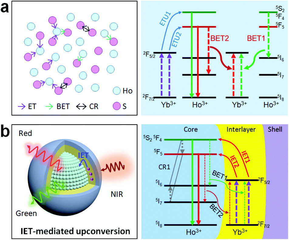 | ||
| Fig. 1 (a) Left: Schematic of the deleterious quenching interactions between Ho3+ and the sensitizer S (e.g., Yb3+) in a codoping system, in particular at high dopant concentrations. Right: Two typical back energy transfer processes (BET1 and BET2) that may quench the red and green emitting energy levels of Ho3+ for a Ho3+/Yb3+ codoped system. (b) Proposed mechanistic model (left) and possible ionic interactions (right) when using interfacial energy transfer to activate the holmium sublattice toward the upconversion in a core–shell–shell nanostructure in which the activator and sensitizer are spatially separated into different layers. ETU, BET, IET, and CR stand for energy transfer upconversion, back energy transfer, interfacial energy transfer, and cross-relaxation, respectively. | ||
Herein, we propose a mechanistic core–shell design using interfacial energy transfer (IET) to enable the upconversion as well as a color tuning of the Ho lattice (Fig. 1b). This design consisted of a holmium lattice core and a sensitizing shell layer to harvest the incident irradiation energy, and it could effectively reduce the unwanted interaction between Ho3+ and the sensitizer by spatially separating them into different regions, only leaving the possibility for interfacial energy transfers with enhanced upconversion. By additionally introducing Nd3+ as the sensitizer, it also allowed the use of 808 nm excitation wavelength. Moreover, a smart control of the Ho3+–Yb3+ interactions in the proposed core–shell–shell nanostructure further led to a gradual color change from red to yellowish green under non-steady state excitation, which shows great promise for application in anti-counterfeiting. Details of the ionic interactions are also discussed. Our results present a simple but effective conceptual model for the activation of the holmium lattice with intense upconversion performance, and should further contribute to the development of a new class of luminescent materials toward versatile frontier applications.
2. Experimental
Materials
The chemicals, including holmium(III) acetate hydrate (99.9%), ytterbium(III) acetate hydrate (99.99%), yttrium(III) acetate hydrate (99.9%), neodymium(III) acetate hydrate (99.9%), erbium(III) acetate hydrate (99.9%), thulium(III) acetate hydrate (99.9%), oleic acid (OA, 90%), 1-octadecene (ODE; >90%), and cyclohexane, were purchased from Sigma-Aldrich. Ammonium fluoride (NH4F; >98%) and sodium hydroxide (NaOH; >98%) were purchased from Alfa Aesar. Ethanol was purchased from Aladdin Company. All the reagents were used without further purification.Synthesis of nanoparticles
Characterization
Powder X-ray diffraction was performed on the samples using a Philips Model PW1830 X-ray powder diffractometer with Cu Kα radiation (λ = 1.5406 Å). Low-resolution and high-resolution transmission electron microscopy (TEM) measurements and selected area electron diffraction patterns were performed on a JEM 2100F TEM (200 kV). Elemental mapping was measured by energy dispersive X-ray spectroscopy (EDS). The upconversion emission spectra were collected by a Zolix spectrofluorometer (OmniFluo990) equipped with 980 and 808 nm laser diodes. The decay curves were measured using the same spectrofluorometer with a pulsed laser, and the lifetime values were determined through fitting the decay curves by a single-exponential equation: I = I0![[thin space (1/6-em)]](https://www.rsc.org/images/entities/char_2009.gif) exp(−t/τ), where I0 is the initial emission intensity at t = 0 and τ is the lifetime. The emission photographs and pattern were taken by a digital camera with an exposure time of 0.3 s.
exp(−t/τ), where I0 is the initial emission intensity at t = 0 and τ is the lifetime. The emission photographs and pattern were taken by a digital camera with an exposure time of 0.3 s.
3. Results and discussion
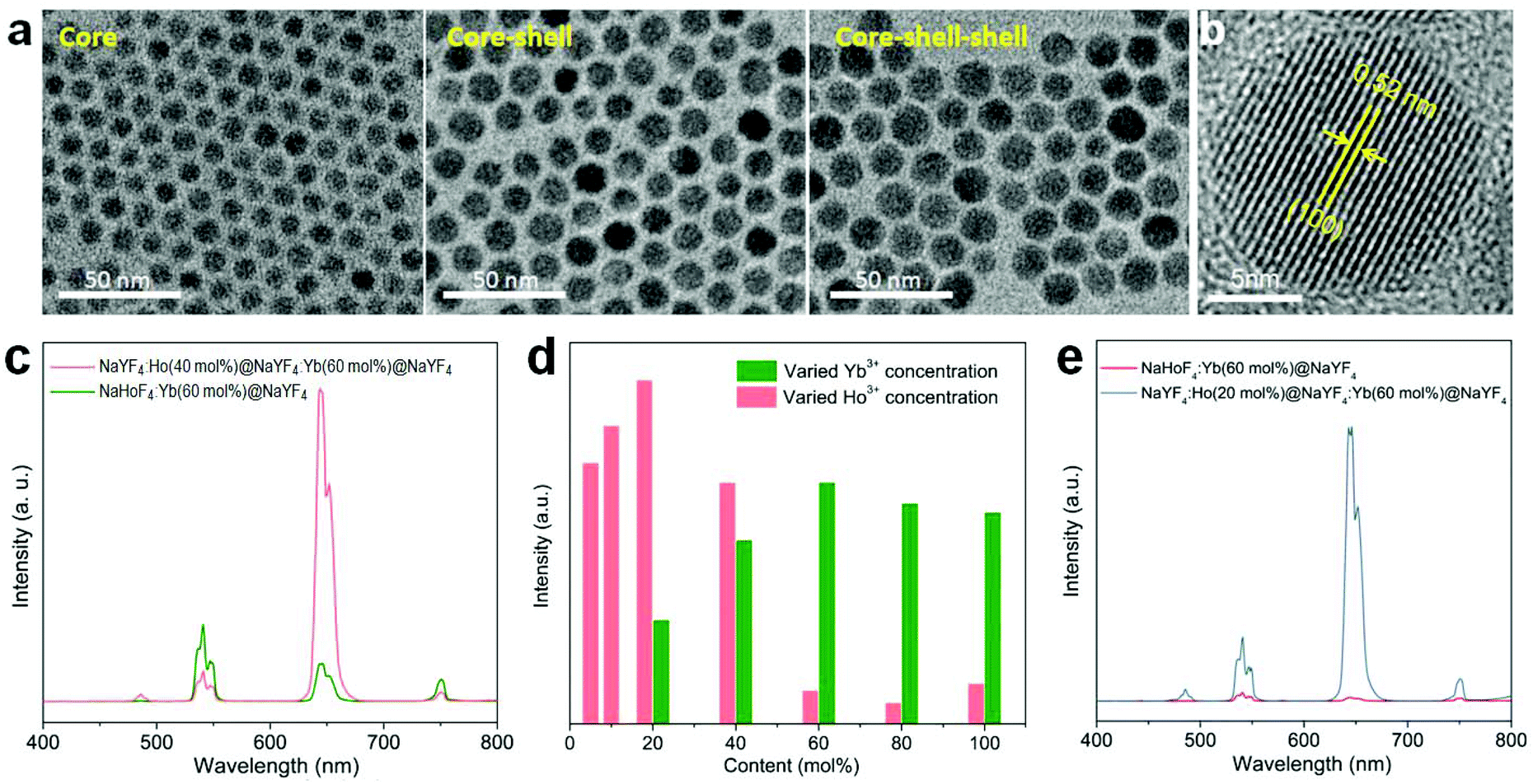
Since the holmium lattice is non-responsive to the commonly used 980 nm excitation wavelength, we first synthesized a series of Yb3+-doped NaHoF4 nanoparticles by a co-precipitation method,17 where Yb3+ was used as the sensitizer. As shown in Fig. 2a, these samples showed good nanoparticles morphology with a monodisperse feature when the Yb3+ concentration was under 40 mol%, while they exhibited irregular shapes at much higher concentration. Besides, the average size of the core increased with increasing the Yb3+-doping concentration (Fig. S1†), which might be due to the intrinsic limit of the co-precipitation chemical method.20,39–42 To reveal the structure property, the X-ray diffraction (XRD) patterns were measured. As shown in Fig. 2b, the XRD patterns presented a constant variation from hexagonal to cubic phase with increasing the Yb3+ concentration in the nanoparticles.39 When the dopant concentration was less than 70 mol%, the diffraction peaks matched well with the standard card of hexagonal phase NaHoF4 (JCPDS-018-1253). In contrast, the cubic phase appeared and became stronger with further lifting the Yb3+ concentration, and when Yb3+ was 100%, it was nearly in the pure cubic phase (JCPDS-077-2043). Moreover, the (110) diffraction peak (inset of Fig. 2b) showed a subtle shift to larger angles, which could be attributed to the lattice shrinkage due to the substitution of smaller radius Yb3+ for that of Ho3+. Besides, the observation of narrower diffraction peaks suggested an increase in the average size of the nanoparticles with increasing the Yb3+ concentration, which is consistent with the TEM results (Fig. 2a and Fig. S1†). | ||
| Fig. 2 (a) TEM images of the NaHoF4:Yb3+ (0–100 mol%) core nanoparticles. (b) X-ray diffraction patterns of (a) samples. Inset shows the enlarged (110) diffraction peak for the samples with the Yb3+ concentration from 0 to 60 mol%. (c and d) Upconversion emission spectra of the as-prepared NaHoF4:Yb3+(5–60 mol%) core only and NaHoF4:Yb3+(5–60 mol%)@NaYF4 core–shell nanoparticles under 980 nm excitation. (e) CIE coordinates of the emissions from (d) samples. Insets show the corresponding emission photographs under 980 nm excitation. | ||
The upconversion emission spectra of these NaHoF4:Yb3+ core nanoparticles are shown in Fig. 2c. The green upconversion emission from the (5S2,5F4) → 5I8 transition dominated the emission spectra, which showed an increase with increasing Yb3+ concentration (0–60 mol%). The emission spectra of the samples with much higher Yb3+ concentration were not measured because of their poor morphology. The core–shell nanoparticles were further prepared by growing an inert NaYF4 shell to improve the upconversion emission intensity (Fig. S2†). As shown in Fig. 2d, the upconversion emission was greatly enhanced compared to that of the core-only sample (Fig. S3†). Besides the green emission of Ho3+, other typical emissions at 486, 646, and 750 nm were observed, which were due to the transitions (5F3,5F2,3K8) → 5I8, 5F5 → 5I8, and (5S2,5F4) → 5I7, respectively. It was interesting to observe that the emission output showed a gradual color change from red to green as the Yb3+ concentration increased from 5 to 60 mol% (Fig. 2e and Table S1†). In contrast to the commonly observed green upconversion in the regular core–shell nanoparticles, such as NaYF4:Yb/Ho(20/2 mol%)@NaYF4 nanoparticles (Fig. S4a†), the weak green upconversion at high Ho3+ concentration might have originated from the cross-relaxation processes of [(5S2,5F4); 5I8] → [5I4; 5I7] and [(5S2,5F4); 5I7] → [5F5; 5I6], which could severely depopulate the green emission energy levels (Fig. S4b†).43 Note that the red upconversion emission in the core–shell nanostructure quickly rose up after growing the NaYF4 inert shell, indicating that the red emission energy level was more sensitive to the surface quenching than the green emission energy level.
In order to check the possibility of our design being able to improve the upconversion through the IET approach, we prepared NaYF4:Ho(40 mol%)@NaYF4:Yb(60 mol%)@NaYF4 core–shell–shell nanoparticles with a spatial separation of Ho3+ and Yb3+ in the core and interlayer, respectively (Fig. 3a,b; Fig. S5 and S6†). The core–shell–shell nanostructure was confirmed by the size increase of the initial core nanoparticles after growing the shell and shell–shell layers (Fig. S5b†). As displayed in Fig. 3c, the typical Ho3+ emissions were recorded. More importantly, the total upconversion emission intensity was markedly enhanced in contrast to the NaHoF4:Yb(60 mol%)@NaYF4 core–shell nanoparticles under identical excitation condition, evidencing the effectiveness of our design. The decrease in the 541 and 750 nm emissions may be attributed to the cross-relaxation CR1 as shown in Fig. 1b.35 Note that the interfacial energy transfer was primarily confined in the range of around 1.6–2.1 nm,36 whereby most of the Yb3+ ions in the interfacial layer were able to participate in the energy transfer to Ho3+ in the core, and the Ho3+ ions far away from the interface could be activated through cross-relaxation.35 On the other hand, the cation intermixing effect could not be taken into consideration due to the relatively low synthesizing temperature.43 Further experiments indicated that the concentrations of Ho3+ at 20 mol% and Yb3+ at 60 mol% presented the best upconversion emissions with remarkable enhancement (Fig. 3d,e; Fig. S7 and S8†). These results indicated that the spatial separation of Yb3+ and Ho3+ in different regions works well in reducing the deleterious back energy transfer (BET) channels, such as [(5S2,5F4); 5I6] → [2F7/2; 2F5/2]; and [5F5; 5I7] → [2F7/2; 2F5/2] from Ho3+ to Yb3+ at the core–shell interface.44,45 Thus, the IET-mediated core–shell nanostructure design was confirmed to be a much more effective approach to the upconversion of the heavy doping of Ho3+ ions in contrast to the conventional codoping scheme with a much lower dopant concentration (e.g. 2 mol% Ho3+).
 | ||
| Fig. 3 (a) TEM images of the NaYF4:Ho(40 mol%) core, NaYF4:Ho(40 mol%)@NaYF4:Yb(60 mol%) core–shell, and NaYF4:Ho(40 mol%)@NaYF4:Yb(60 mol%)@NaYF4 core–shell–shell nanoparticles. (b) The high-resolution TEM image of the core–shell–shell nanoparticles. (c) A comparison of the upconversion emission spectra of as-prepared NaYF4:Ho(40 mol%)@NaYF4:Yb(60 mol%)@NaYF4 core–shell–shell and NaHoF4:Yb(60 mol%)@NaYF4 core–shell nanoparticles under 980 nm excitation. (d) Dependence of the overall upconversion emission intensity of the NaYF4:Ho(5–100 mol%)@NaYF4:Yb(20–100 mol%)@NaYF4 core–shell–shell nanoparticles with a tuning of the concentrations of Ho3+ in the core and Yb3+ in the interlayer, respectively. (e) Comparative upconversion emission spectra from the optimized NaYF4:Ho(20 mol%)@NaYF4:Yb(60 mol%)@NaYF4 core–shell–shell nanoparticles and NaHoF4:Yb(60 mol%)@NaYF4 core–shell nanoparticles under identical measurement conditions. | ||
To further figure out the mechanism of IET in such a core–shell nanostructure, we prepared NaHoF4@NaYF4:Yb core–shell nanoparticles with tuning the Yb3+ concentration (5–100 mol%) in the shell layer (Fig. S9 and S10†). The upconversion emission spectra are shown in Fig. 4a, indicating an initial increase and then a decline with increasing the Yb3+ concentration, and the highest luminescence intensity was obtained at 20 mol% Yb3+. The decrease in the emission intensity may be due to the strong BET channels at the core–shell interfacial area as well as the energy loss from the energy migratory feature of Yb3+. During this process, an emission color change from red to yellow was also observed, and the corresponding CIE coordinates are plotted in Fig. 4b (Table S2†). From the above result, it was also found that the red upconversion emission was more sensitive to the change of Yb3+ concentration in the shell layer. This might be due to the more efficient BET2 process of [5F5; 5I7] → [2F7/2; 2F5/2] (Fig. 4c–e). There was a slight decrease in the lifetime of the red upconversion emission (Fig. 4c), while almost no change was observed for that of the green upconversion emission (Fig. 4d). This may also suggest a weak cross-relaxation at the green emission levels that could partially compensate the negative effect of the BET1 process. Note that in such a core–shell structure, due to the lack of protection from surface defects, the upconversion emission intensity of NaHoF4@NaYF4:Yb(20 mol%) was much weaker than that of the NaHoF4:Yb(20 mol%)@NaYF4 nanoparticles (Fig. 4f). In contrast, after coating an NaYF4 inert shell outside the NaHoF4@NaYF4:Yb(20 mol%), the upconversion emission intensity was greatly enhanced more than that from the codoping sample (Fig. 4f; Fig. S11†). These results demonstrated that the smart control of IET in a core–shell–shell structure is beneficial to improving the upconversion emission toward brighter output.
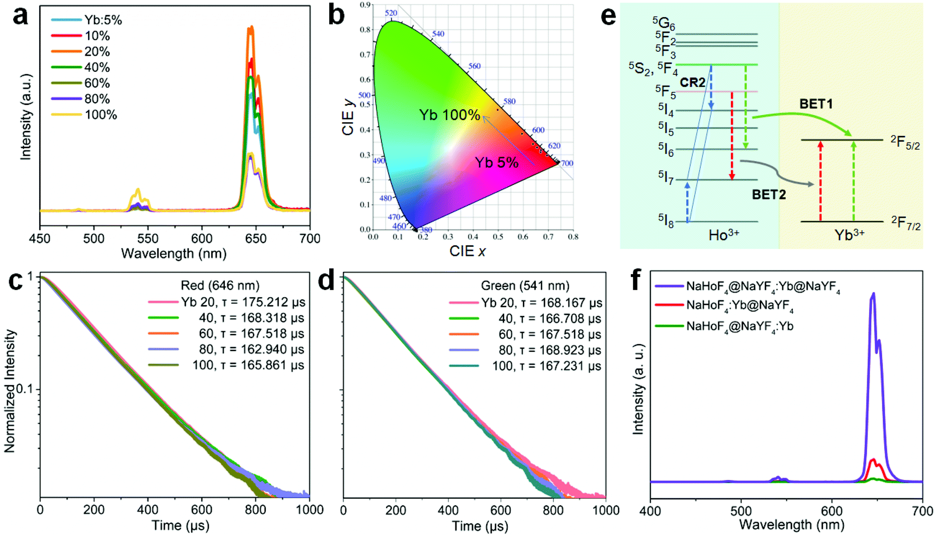 | ||
| Fig. 4 (a) Upconversion emission spectra of NaHoF4@NaYF4:Yb(5–100 mol%) core–shell nanoparticles under 980 nm excitation. (b) CIE coordinates of the emissions from (a) samples. (c and d) Decay curves of the upconversion emissions measured at (c) 646 nm and (d) 541 nm under pulsed 980 nm excitation. (e) Possible back energy transfer processes for decreasing the red and green upconversion emissions under 980 nm excitation. (f) Comparison of the upconversion emission spectra of the as-prepared NaHoF4@NaYF4:Yb(20 mol%) core–shell, NaHoF4:Yb(20 mol%)@NaYF4 core–shell, and NaHoF4@NaYF4:Yb(20 mol%)@NaYF4 core–shell–shell nanoparticles under 980 nm excitation. | ||
Next, we investigated how to realize the upconversion of the holmium lattice upon excitation at the 808 nm wavelength, an important wavelength for biological applications. Because there is no relevant energy levels matching with this wavelength, Ho3+ itself is non-responsive to the 808 nm irradiation. Consequently, here the NaHoF4@NaYF4:Yb/Nd core–shell nanostructure was proposed and Nd3+ was newly introduced into the shell as the sensitizer (Fig. 5a–c). As shown in Fig. 5a and b, an intense upconversion of Ho3+ was indeed observed for this design and the optimal Yb3+ and Nd3+ doping concentrations were found to be 20 mol% and 30 mol%, respectively. It should be noted that this design was much better than that of a simple Ho3+/Yb3+/Nd3+ codoped system (Fig. S12†). These results confirmed that the Nd3+ → Yb3+ → Ho3+ energy transfer in a core–shell nanostructure design is an efficient way to activate Ho3+ under 808 nm irradiation (Fig. 5c). On the other hand, the presence of Nd3+ would sharply decrease the emission of Ho3+ upon 980 nm excitation due to the occurrence of other quenching channels from Ho3+ to Nd3+ (Fig. S13†).
 | ||
| Fig. 5 (a and b) Upconversion emission spectra of NaHoF4@NaYF4:Yb(0–60 mol%) and NaHoF4@NaYF4:Yb (20 mol%)/Nd (10–70 mol%) core–shell nanoparticles under 980 and 808 nm excitations, respectively. (c) Schematic of the energy transport processes in the Nd3+-sensitized upconversion system. | ||
Despite the activation through 808 nm excitation, the total emission color was mainly in the red output. To further expand the color gamut, we designed NaHoF4@NaYF4:Yb(0–100 mol%)@NaYF4:Yb/Nd to tune the upconversion dynamics through IET interactions between Ho3+ and Yb3+ at the core–interlayer interfacial area (Fig. 6a). As shown in Fig. 6b, the green and red emission showed an initial rising and then falling trend with increasing the Yb3+ concentration in the interlayer. More interestingly, the upconversion emission intensity of the red-to-green ratio gradually descended from 27.4 to 2.1, which means that a color change from red to yellowish green was obtained (Fig. 6c and Table S3†). The Nd3+ ions in the outmost shell layer first absorbed the 808 nm excitation energy, which was then transferred to Yb3+ in the same shell, followed by Yb3+–Yb3+ migration until reaching the Ho3+ lattice with its upconversion emissions.46–48 The back energy transfers from Ho3+ to Yb3+ played the key roles in tuning the emission colors. This design also allowed for 980 nm excitation with a similar color gamut (Fig. S14 and Table S4†). Thus, one can see that Yb3+ in the interlayer plays two roles: one, as the migrator to support the energy transport from the outermost shell to the core, and the other one, as the energy trapper to mediate the populations of Ho3+ at its red or green emission energy level.
 | ||
| Fig. 6 (a) Schematic of using the nanostructure to manipulate the upconversion emission colors of the holmium lattice through core–interlayer interfacial energy transfer processes between Ho3+ and Yb3+ upon 808 nm excitation. (b) Upconversion emission spectra of as-prepared NaHoF4@NaYF4:Yb(0–100 mol%)@NaYF4:Nd/Yb(30/20 mol%) core–shell–shell nanoparticles under 808 nm excitation. Inset shows the dependence of the red-to-green emission intensity ratio as a function of the Yb3+ concentration in the interlayer. (c) CIE coordinates of the emissions from (b) samples. (d and e) Upconversion emission spectra of (d) NaHoF4@NaYF4:Yb(40 mol%)@NaYF4:Nd/Yb(30/20 mol%) and (e) NaHoF4@NaYbF4@NaYF4:Nd/Yb(30/20 mol%) with different ICG dye concentrations under 808 nm excitation. Insets show the corresponding emission photographs. (f) Dependence of upconversion red emission to green emission on pump power densities of 808 nm excitation for (d) and (e) samples. | ||
To further enhance the upconversion emission intensity, we introduced ICG dyes as an additional sensitizer to improve the excitation energy harvest at 808 nm. The ICG dyes have much higher absorption capability than that of Nd3+ at around 808 nm wavelength.49,50 As shown in Fig. 6d and e, the red and green emission were greatly enhanced in comparison with the control sample without surface attaching the ICG dyes. The emission colors exhibited a stable feature in a large excitation power density range (Fig. 6f and Fig. S15†), laying a solid foundation for frontier applications.
To shed more light on the ionic interactions between Ho3+ and Yb3+, the upconversion performance under non-steady state excitation was further measured. The upconversion emission of Ho3+ showed a color change from red to yellowish green as the pulse width of the laser decreased (Fig. 7a; Fig. S16 and Table S5†). This might be due to the indirect upconversion process of the red upconversion emission that is usually obtained through relaxation from the intermediate states of 5I6 to 5I7 before the upconversion transition to the red emission level (Fig. 7b). This was supported by the relatively slow rising process of the red upconversion emission in comparison to that of the green emission (Fig. 7c). Note that the cross-relaxation occurring at the green emission (5F4,5S2) level may also made a contribution because the red upconversion emission showed a more rapid rising process than that of the conventional NaYF4:Yb/Ho(20/2 mol%) nanoparticles (Fig. 7d). Both origins are schematically shown in Fig. 7b. Such a tunable emission color merit holds great promise in anti-counterfeiting applications (Fig. 7e). For a given cherry pattern, we concealed the numbers “2021” below it with the first one using the sample in Fig. 7a and the others by the control upconversion nanoparticles with different emission colors (Fig. S17†). Under continuous-wave (c.w.) light irradiation, the patterned numbers showed a red “2”, blue “0”, red “2”, and green “1” from left to right. When using the pulse excitation laser with a reduction of the pulse width, the first number “2” showed a gradual color change to light yellow due to the presence of the green upconversion emission; while there was no color change for the other numbers during this process, meaning that the concealed initial number “2” was the only one distinguishable under short pulse excitation. This feature provides an additional temporal parameter for multi-level anti-counterfeiting in contrast to the commonly used upconversion emission color and/or lifetime tuning techniques.
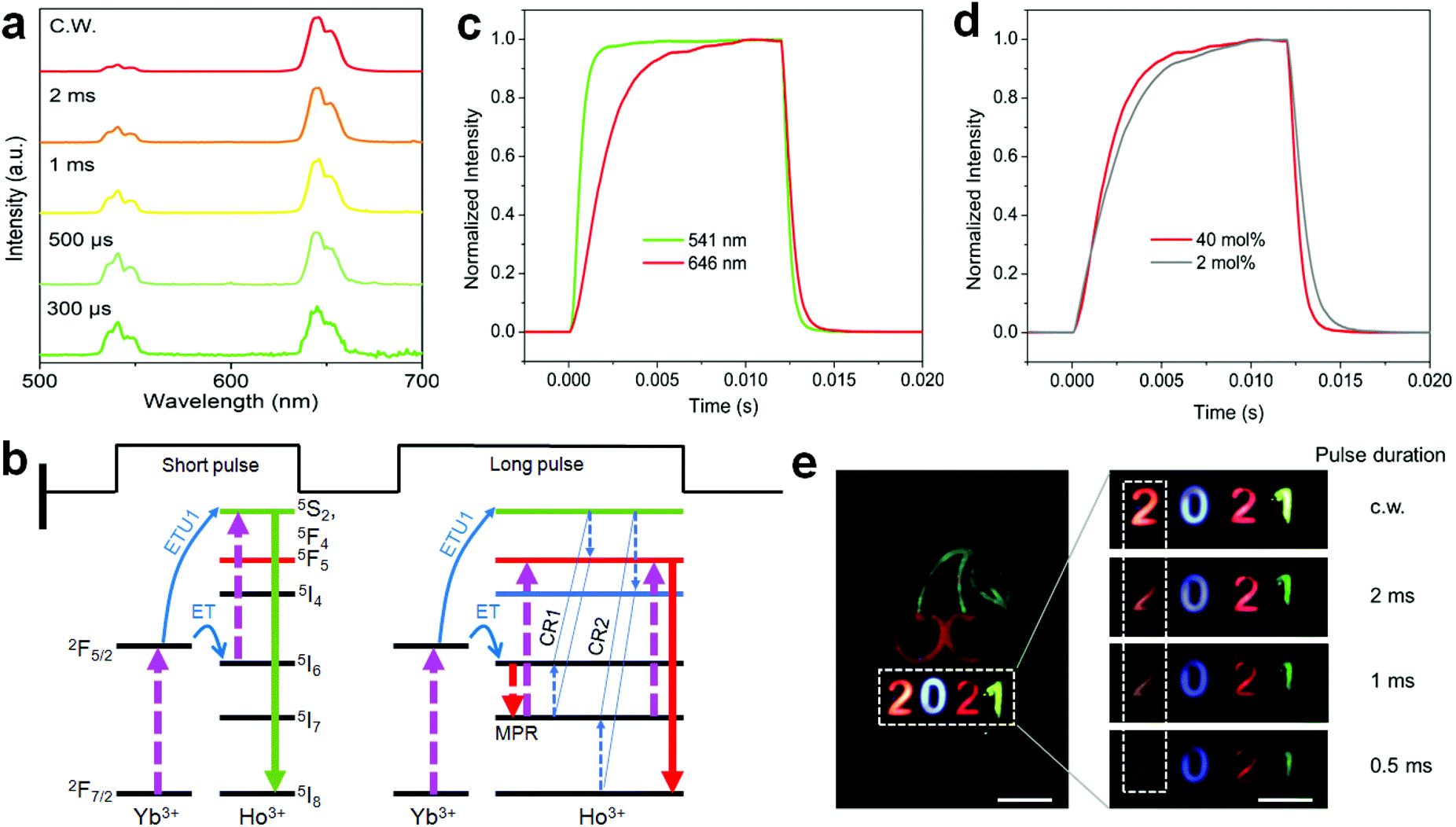 | ||
| Fig. 7 (a) Upconversion emission spectra of NaYF4:Ho(40 mol%)@NaYF4:Yb(60 mol%)@NaYF4 core–shell–shell nanoparticles under pulsed 980 nm excitation with a tuning of the pulse duration. (b) Schematic of the possible processes for the reduction of the red upconversion under non-steady state excitation. (c) Time-dependent emission profiles of Ho3+ at 541 and 646 nm of (a) sample under 980 nm irradiation with a pulse duration of 12 ms (50 Hz). (d) A comparison of the time-dependent red upconversion emission profiles from the (a) sample and NaYF4:Yb/Ho(20/2 mol%)@NaYF4 core–shell nanoparticles. (e) Schematic of decoding the concealed information on the cherry pattern under pulsed 980 nm irradiation (right panels) in which only the initial number “2” shows a color change with reducing the pulse duration. Scale bars, 0.5 cm. | ||
4. Conclusion
In conclusion, we demonstrated a mechanical design for constructing interfacial energy transfer in Ho3+–Yb3+ separately doped core–shell structures toward enhanced photon upconversion. The spatial separation of the sensitizer and activator could effectively reduce the back energy transfer channels that occur in the heavily doped luminescent system. By further designing the Yb3+/Nd3+ dual-sensitizing shell, 808 nm excitation wavelength was also achieved. A fine manipulation of the ionic interactions between Ho3+ and Yb3+ at the interfacial area in a core–shell–shell nanostructure resulted in a gradual color change from red to green. The upconversion of the red upconversion also exhibited a dynamic dependence on the pulse duration. The fine control of the emission colors shows promise in applications in information security. The conceptual model described in this work not only helps gain a deep insight into the luminescence mechanism of lanthanides as well as the lanthanide sublattice but also contributes to the design of a new class of versatile luminescent materials toward frontier applications.Conflicts of interest
There are no conflicts to declare.Acknowledgements
This work is supported by the National Natural Science Foundation of China (Grant No. 51972119), the Fundamental Research Funds for the Central Universities (2020ZYGXZR100), the Yong Top-notch Talents of Guangdong Pearl River Talents Program (2017GC010278), and the Local Innovative and Research Teams Project of Guangdong Pearl River Talents Program (2017BT01X137).Notes and references
- B. Zhou, B. Shi, D. Jin and X. Liu, Nat. Nanotechnol., 2015, 10, 924–936 CrossRef CAS.
- H. Dong, S.-R. Du, X.-Y. Zheng, G.-M. Lyu, L.-D. Sun, L.-D. Li, P.-Z. Zhang, C. Zhang and C.-H. Yan, Chem. Rev., 2015, 115, 10725–10815 CrossRef CAS.
- X. Wang, R. R. Valiev, T. Y. Ohulchanskyy, H. Agren, C. Yang and G. Chen, Chem. Soc. Rev., 2017, 46, 4150–4167 RSC.
- J. Zhou, A. I. Chizhik, S. Chu and D. Jin, Nature, 2020, 579, 41–50 CrossRef CAS.
- Y. Wang, K. Zheng, S. Song, D. Fan, H. Zhang and X. Liu, Chem. Soc. Rev., 2018, 47, 6473–6485 RSC.
- D. Hudry, I. A. Howard, R. Popescu, D. Gerthsen and B. S. Richards, Adv. Mater., 2019, 31, 1900623 CrossRef.
- Z. Zhang, S. Shikha, J. Liu, J. Zhang, Q. Mei and Y. Zhang, Anal. Chem., 2019, 91, 548–568 CrossRef CAS.
- X. Zhu, Q. Su, W. Feng and F. Li, Chem. Soc. Rev., 2017, 46, 1025–1039 RSC.
- J. Xu, J. Zhou, Y. Chen, P. Yang and J. Lin, Coord. Chem. Rev., 2020, 415, 213328 CrossRef CAS.
- Y. Zhong, Z. Ma, S. Zhu, J. Yue, M. Zhang, A. L. Antaris, J. Yuan, R. Cui, H. Wan, Y. Zhou, W. Wang, N. F. Huang, J. Luo, Z. Hu and H. Dai, Nat. Commun., 2017, 8, 737 CrossRef.
- F. Wang, S. Wen, H. He, B. Wang, Z. Zhou, O. Shimoni and D. Jin, Light: Sci. Appl., 2018, 7, 18007 CrossRef CAS.
- Y. Li, S. Zeng and J. Hao, ACS Nano, 2019, 13, 248–259 CrossRef CAS.
- P. Huang, W. Zheng, Z. Gong, W. You, J. Wei and X. Chen, Mater. Today Nano, 2019, 5, 100031 CrossRef.
- C. Liu, B. Liu, J. Zhao, Z. Di, D. Chen, Z. Gu, L. Li and Y. Zhao, Angew. Chem., Int. Ed., 2020, 59, 2634–2638 CrossRef CAS.
- R. Deng, F. Qin, R. Chen, W. Huang, M. Hong and X. Liu, Nat. Nanotechnol., 2015, 10, 237–242 CrossRef CAS.
- W. Ren, G. Lin, C. Clarke, J. Zhou and D. Jin, Adv. Mater., 2020, 32, 1901430 CrossRef CAS.
- B. Zhou, J. Huang, L. Yan, X. Liu, N. Song, L. Tao and Q. Zhang, Adv. Mater., 2019, 31, 1806308 Search PubMed.
- H. Liu, J. Xu, H. Wang, Y. Liu, Q. Ruan, Y. Wu, X. Liu and J. K. Yang, Adv. Mater., 2019, 31, 1807900 CrossRef.
- A. Fernandez-Bravo, K. Yao, E. S. Barnard, N. J. Borys, E. S. Levy, B. Tian, C. A. Tajon, L. Moretti, M. V. Altoe, S. Aloni, K. Beketayev, F. Scotognella, B. E. Cohen, E. M. Chan and P. J. Schuck, Nat. Nanotechnol., 2018, 13, 572–577 CrossRef CAS.
- X. Chen, L. Jin, W. Kong, T. Sun, W. Zhang, X. Liu, J. Fan, S. F. Yu and F. Wang, Nat. Commun., 2016, 7, 10304 CrossRef CAS.
- N. J. Johnson, S. He, S. Diao, E. M. Chan, H. Dai and A. Almutairi, J. Am. Chem. Soc., 2017, 139, 3275–3282 CrossRef CAS.
- Q. Chen, X. Xie, B. Huang, L. Liang, S. Han, Z. Yi, Y. Wang, Y. Li, D. Fan, L. Huang and X. Liu, Angew. Chem., Int. Ed., 2017, 56, 7605–7609 CrossRef CAS.
- L. Yan, B. Zhou, N. Song, X. Liu, J. Huang, T. Wang, L. Tao and Q. Zhang, Nanoscale, 2018, 10, 17949–17957 RSC.
- X. Li, Z. Guo, T. Zhao, Y. Lu, L. Zhou, D. Zhao and F. Zhang, Angew. Chem., Int. Ed., 2016, 55, 2464–2469 CrossRef CAS.
- H. Dong, L. D. Sun, W. Feng, Y. Y. Gu, F. Y. Li and C. H. Yan, ACS Nano, 2017, 11, 3289–3297 CrossRef CAS.
- K. Zheng, S. Han, X. Zeng, Y. Wu, S. Song, H. Zhang and X. Liu, Adv. Mater., 2018, 30, e1801726 CrossRef.
- M. Wu, L. Yan, T. Wang, B. Zhou and Q. Zhang, Adv. Funct. Mater., 2019, 29, 1804160 CrossRef.
- Q. Mei, A. Bansal, M. K. G. Jayakumar, Z. Zhang, J. Zhang, H. Huang, D. Yu, C. J. A. Ramachandra, D. J. Hausenloy, T. W. Soong and Y. Zhang, Nat. Commun., 2019, 10, 4416 CrossRef.
- J. Zhao, D. Jin, E. P. Schartner, Y. Lu, Y. Liu, A. V. Zvyagin, L. Zhang, J. M. Dawes, P. Xi, J. A. Piper, E. M. Goldys and T. M. Monro, Nat. Nanotechnol., 2013, 8, 729–734 CrossRef CAS.
- W. Wei, G. Chen, A. Baev, G. S. He, W. Shao, J. Damasco and P. N. J. Prasad, J. Am. Chem. Soc., 2016, 138, 15130–15133 CrossRef CAS.
- B. Zhou, W. Yang, S. Han, Q. Sun and X. Liu, Adv. Mater., 2015, 27, 6208–6212 CrossRef CAS.
- S. Viswanathan, Z. Kovacs, K. N. Green, S. J. Ratnakar and A. D. Sherry, Chem. Rev., 2010, 110, 2960–3018 CrossRef CAS.
- M. Norek and J. A. Peters, Prog. Nucl. Magn. Reson. Spectrosc., 2011, 59, 64–82 CrossRef CAS.
- D. Ni, W. Bu, S. Zhang, X. Zheng, M. Li, H. Xing, Q. Xiao, Y. Liu, Y. Hua and L. Zhou, Adv. Funct. Mater., 2014, 24, 6613–6620 CrossRef CAS.
- Y. Kuang, T. Li, T. Jia, A. Gulzar, C. Zhong, S. Gai, F. He, P. Yang and J. Lin, Small, 2020, 16, 2003799 CrossRef CAS.
- B. Zhou, L. Yan, L. Tao, N. Song, M. Wu, T. Wang and Q. Zhang, Adv. Sci., 2018, 5, 1700667 CrossRef.
- B. Zhou, L. Tao, Y. Chai, S. P. Lau, Q. Zhang and Y. H. Tsang, Angew. Chem., Int. Ed., 2016, 55, 12356–12360 CrossRef CAS.
- B. Zhou, Q. Li, L. Yan and Q. Zhang, J. Rare Earths, 2020, 38, 474–482 CrossRef.
- J. Ren, G. Jia, Y. Guo, A. Wang and S. Xu, J. Phys. Chem. C, 2016, 120, 1342–1351 CrossRef CAS.
- F. Wang, Y. Han, C. S. Lim, Y. Lu, J. Wang, J. Xu, H. Chen, C. Zhang, M. Hong and X. Liu, Nature, 2010, 463, 1061–1065 CrossRef CAS.
- B. Shen, S. Cheng, Y. Gu, D. Ni, Y. Gao, Q. Su, W. Feng and F. Li, Nanoscale, 2017, 9, 1964–1971 RSC.
- C. Ma, X. Xu, F. Wang, Z. Zhou, D. Liu, J. Zhao, M. Guan, C. I. Liang and D. Jin, Nano Lett., 2017, 17, 2858–2864 CrossRef CAS.
- B. Chen, D. Peng, X. Chen, X. Qiao, X. Fan and F. Wang, Angew. Chem., Int. Ed., 2015, 54, 12788–12790 CrossRef CAS.
- A. Pilch, C. Wuerth, M. Kaiser, D. Wawrzynczyk, M. Kurnatowska, S. Arabasz, K. Prorok, M. Samoc, W. Strek, U. Resch-Genger and A. Bednarkiewicz, Small, 2017, 13, 1701635 CrossRef.
- Y. Kuang, J. Xu, C. Wang, T. Li, S. Gai, F. He, P. Yang and J. Lin, Chem. Mater., 2019, 31, 7898–7909 CrossRef CAS.
- H. Wen, H. Zhu, X. Chen, T. F. Hung, B. Wang, G. Zhu, S. F. Yu and F. Wang, Angew. Chem., Int. Ed., 2013, 52, 13419–13423 CrossRef CAS.
- Y. Fan, P. Wang, Y. Lu, R. Wang, L. Zhou, X. Zheng, X. Li, J. A. Piper and F. Zhang, Nat. Nanotechnol., 2018, 13, 941–946 CrossRef CAS.
- B. Zhou, L. Yan, J. Huang, X. Liu, L. Tao and Q. Zhang, Nat. Photonics, 2020, 14, 760–766 CrossRef.
- G. Chen, J. Damasco, H. Qiu, W. Shao, T. Y. Ohulchanskyy, R. R. Valiev, X. Wu, G. Han, Y. Wang, C. Yang, H. Agren and P. N. Prasad, Nano Lett., 2015, 15, 7400–7407 CrossRef CAS.
- W. Shao, G. Chen, A. Kuzmin, H. L. Kutscher, A. Pliss, T. Y. Ohulchanskyy and P. N. Prasad, J. Am. Chem. Soc., 2016, 138, 16192–16195 CrossRef CAS.
Footnote |
| † Electronic supplementary information (ESI) available. See DOI: 10.1039/d0nr09068a |
| This journal is © The Royal Society of Chemistry 2021 |