
Phosphatized mild-prepared-NiCo LDHs cabbage-like spheres exhibit excellent performance as a supercapacitor electrode†
Guorong
Wang
 a,
Yanbing
Li
a,
Tiansheng
Zhao
*b and
Zhiliang
Jin
*a
a,
Yanbing
Li
a,
Tiansheng
Zhao
*b and
Zhiliang
Jin
*a
aSchool of Chemistry and Chemical Engineering, Ningxia Key Laboratory of Solar Chemical Conversion Technology, Key Laboratory for Chemical Engineering and Technology, State Ethnic Affairs Commission, North Minzu University, Yinchuan 750021, P. R. China. E-mail: zl-jin@nun.edu.cn
bState Key Laboratory of High-Efficiency Utilization of Coal and Green Chemical Engineering, Ningxia University, Yinchuan 750021, China. E-mail: zhaots@nxu.edu.cn
First published on 17th November 2020
Abstract
Layered double hydroxides (LDHs) have been paid more attention in supercapacitors due to their advantages in structure and performance. In particular, NiCo LDHs have been extensively studied due to its high theoretical specific capacity. Unfortunately, the exerted capacity is much lower than the theoretical value due to its poor electron conductivity. In this work, P@NiCo LDHs cabbage-like spheres were successfully synthesized by a mild co-precipitation strategy and a subsequent phosphating treatment method. Owing to the generation of metal phosphides, which is endowed with good electron conduction ability, the specific capacitance of the P@NiCo LDHs (536 C g−1) is 1.88 times greater than the NiCo LDHs (285.8 C g−1) at a current density of 1 A g−1. In addition, the prepared electrode provided a good cycling performance with no difference from the initial capacitance at 10 A g−1 after 5000 cycles. Besides, the symmetric supercapacitor device with vacuum plastic packaging structure was prepared, which exhibits an energy density of 7.83 W h kg−1 at 300 W kg−1. This work indicates that the phosphating strategy is an effective way to improve the performance of LDH-based materials for supercapacitors.
1. Introduction
With the accelerating development of human society, especially the leap in the development of computer and artificial intelligence technology, human activities have become faster and more convenient. This requires corresponding reforms in energy sources because traditional energy forms cannot meet the requirements of new devices, and most traditional energy sources are not friendly to the environment.1–3 Secondary batteries, due to their high energy density and low cost, play an important role in the energy supply of new electronic devices and mobile devices.4–7 However, the inherent Faraday reaction characteristics limit the charging and discharging speed, cycle life and its wide application.8 Supercapacitors (SCs) are a kind of energy storage element with the characteristics of fast energy storage speed and stable circulation, which have attracted considerable interest from researchers in recent years.9–12 Regrettably, the development of supercapacitors is still unable to completely meet the growing demands for efficient energy storage, which means that supercapacitors with high energy density, power density and stability are urgently needed.13,14Layered double hydroxides (LDHs) are a class of multi-metal clay materials that are constituted by brucite layers of metal cations octahedrally surrounded by hydroxyl-forming M2+(OH)6/M3+/4+(OH)6 octahedra;1 M is mainly the transition metal element, which makes this kind of material environment-friendly and is easy to get. The special layered structure of LDHs enables the transition metal atoms to be evenly distributed in materials, so that they have more active bits and have a high theoretical specific capacity in the application of supercapacitors. Moreover, the cations in the main layer can be easily replaced, making this kind of material diversiform and provide a wider range of raw materials for the production of supercapacitor parts. To date, the use of one-dimensional, two-dimensional and three-dimensional nanomaterials such as NiCo LDHs, NiAl LDHs, CoAl LDHs and NiFe LDHs in supercapacitors has been reported.15–18 However, for the LDH supercapacitor in the practical work, the location of the REDOX reaction occurs often on the material surface or near surface; ions in the reaction cannot participate in the reaction of ions parsing from the material body, or the material cannot make contact with the electrolyte, leading to an actual specific capacity that is low. In this way, in the process of repeated charging and discharging, the electrolyte ions cannot be completely released. As time goes by, the material's ability to store charge gradually decreases. Many improvement measures have been studied, compounding with good electrical conductivity materials such as graphene, carbon nanotubes and conductive polymers to improve the specific electrical capacity of materials, and coupling with matrix materials such as SiO2 and nickel foam with good mechanical properties of skeleton structure to comprehensively improve the cyclic stability of materials.
Metal phosphides show excellent performance and potential in the field of electrochemical energy storage due to their metalloid characteristics and good electric conductivity.19 The Qi group introduced nickel–cobalt phosphite into the NiCo LDHs, which accelerated electron transfer and improved the specific electrical capacity of the material.20
In this work, we first synthesized the NiCo LDHs by a mild coprecipitation strategy in an alkaline solution, and then successfully obtained the P@NiCo LDHs cabbage-like sphere electrode material by phosphating treatment strategy. Compared to the NiCo LDHs, the P@NiCo LDHs show higher specific capacitance and good cycling stability, which manifest the phosphating treatment electrical conductivity and stability of the LDH structure. Besides, the symmetric supercapacitor device with vacuum plastic packaging structure was prepared, which shows considerable charge storage capacity and stability. Conclusively, we hold the opinion that the phosphating strategy is an excellent way to improve the performance of the supercapacitors.
2. Experimental
2.1. Preparation of P@NiCo LDHs
All starting materials and solvents were obtained from commercial sources and used without further purification. All chemical reagents are analytical grade, and were purchased from Sinopharm Chemical Reagent Co., Ltd.NiCo-LDHs were fabricated by a moderate one-step chemical coprecipitation way, according to the previously report.15 Typically, 0.214 g nickel chloride hexahydrate (NiCl2·6H2O, ≥98.0%), 0.14 g cobalt chloride hexahydrate (CoCl2·6H2O, ≥99.0%), 0.322 g ammonium chloride (NH4Cl, ≥99.5%) and 0.11 g sodium hydroxide (NaOH, ≥96.0%) were evenly dispersed in 40 mL deionized water in a 50 mL beaker. Then, this beaker was transferred into an oven and heated for 15 h under 55 °C. After reaction, the product was cooled down to 25 °C at ambient temperature, washed several times with deionized water and ethanol, and dried in the oven at 60 °C for 6 h. The resultant products were denoted as 3![[thin space (1/6-em)]](https://www.rsc.org/images/entities/char_2009.gif) :2 NiCo LDHs for further use. Other samples of different Ni/Co proportions were prepared by the same method.
:2 NiCo LDHs for further use. Other samples of different Ni/Co proportions were prepared by the same method.
0.2 g of the above prepared NiCo LDHs template and 0.5 g NaH2PO2 were placed separately on both sides of a long porcelain boat. Then, the porcelain boat was transferred to a tube furnace and heated at 300 °C for 2 h under nitrogen flow at a heating rate of 4 °C min−1. After the phosphating process, the treated P@NiCo LDHs sample was cooled to room temperature, washed with deionized water and dried at 60 °C for 6 h, respectively. Finally, the powder material was ground and collected as the sample to prepare the electrode.
2.2. Characterizations
The crystal phase of the as-prepared samples were characterized by X-ray powder diffraction (XRD) (Rigaku D/max-γB, Japan, 40 kV, 80 mA) with a Cu Kα radiation source (λ = 0.15418 nm). The morphology of the samples were obtained from field emission scanning electron microscopy (FESEM) conducted on a scanning electron microscope (Hitachi SU8020, 5 kV) and transmission electron microscope (TEM) conducted on a transmission electron microscope (JEM-1400, 120 kV). X-ray photoelectron spectral (XPS) measurements were performed on an X-ray photoelectron spectrometer (ESCALAB 250Xi, Al Kα). The specific surface area, pore size and pore volume of the samples were measured at an ASAP 2020M apparatus and analyzed by the Brunauer–Emmett–Teller equation.2.3. Electrochemical measurements
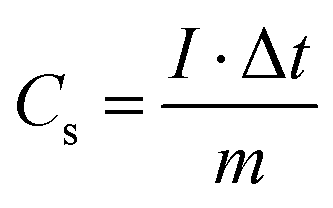
The curves of cyclic voltammetry (CV), galvanostatic charge–discharge (GCD) and electrochemical impedance spectroscopy (EIS) were measured on an electrochemical workstation (CHI-660E, Shanghai Chenhua Instrument Limited Corporation, China). The electrochemical properties of the samples were conducted in a three-electrode system, in which 6 M KOH was the electrolyte, Ag/AgCl was the reference electrode, and platinum was the counter electrode. The working electrode was prepared as follows: 10 mg mixture of P@NiCo LDHs, acetylene black and PVDF (8:1:1) were dissolved in ethanol to form a slurry and pressed onto a nickel foam current collector (1 cm2), and then dried under vacuum overnight at 60 °C. The specific capacitance (SC) of the prepared electrodes was computed from the curve of the galvanostatic charge–discharge, according to the followed equation:11where Cs (C g−1) represents the capacitance value, Δt (s) represents the discharge time, I (A) represents the current value, ΔV (V) represents the potential window, and m (g) represents the quality of the electrode materials.
The P@NiCo LDHs//P@NiCo LDHs symmetrical supercapacitor device was assembled with an all-solid-state strategy, in which the polybenzimidazole (PBI) doped with KOH (PBI-KOH) replaced the separator and liquid electrolyte, as referred to in previous reports.21 In detail, the PBI separator was prepared by drop casting method using PBI dissolved in dimethylacetamide (5 wt%). Two P@NiCo LDHs electrodes of equal mass (about 0.7 mg) acting as the positive and negative electrodes were then sealed with PBI-KOH diaphragm together in a vacuum package. The working area of the device was 1.0 cm2. The CV, GCD and EIS were tested to study the electrochemical properties of this device.
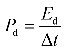
The specific capacitance (Cd, F g−1), energy density (Ed, W h kg−1) and power density (Pd, W kg−1) of the P@NiCo LDHs//P@NiCo LDHs device were calculated according to the following equation,22–24 respectively:
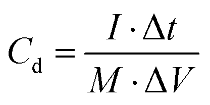

where M is the mass of both electrode materials (g), and ΔV is the discharge voltage window (V). Δt is the discharge time (s).
3. Results and discussion
3.1. The composition and morphology of the prepared materials
The synthesis procedure of the phosphating treated nickel–cobalt layer double hydroxides sample (P@NiCo LDHs) is schematically illustrated in Scheme 1. The Ni/Co hydroxides were formed by the presence of the original Ni2+/Co2+ ions under alkaline conditions, and then aggregated into sheets due to the hydroxylation reaction and existence of high surface energy from nanoscale. Furthermore, the self-assembly occurred and resulted in a stable sphere structure under the action of Ostwald ripening. Finally, the metal phosphating compounds, which are good at conducting electrons, were formed on the surface due to phosphating treatment.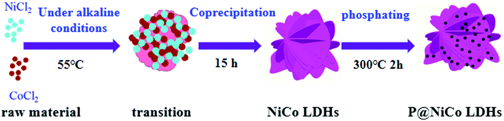 | ||
| Scheme 1 Schematic illustration demonstrating the fabrication procedure of the P@NiCo LDHs. | ||
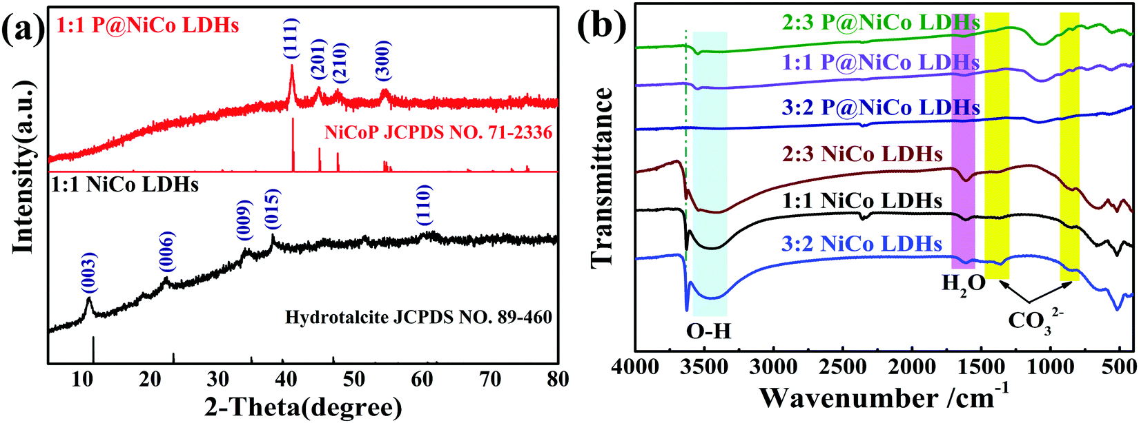
The XRD, FT-IR, XPS, and nitrogen absorption and desorption detection means were used to study its structure and composition. Fig. 1a shows the XRD patterns to study the crystalline structure of the samples. Typically, the diffraction peaks located at 11.4°, 22.7°, 33.8°, 39.1° and 60.22° can be indexed to the (003), (006), (009), (015) and (110) planes of the hydrotalcite-like NiCo LDHs phase (JCPDS No. 89-460), respectively. These results are the same as that of the previously reported NiCo LDHs material.15,25,26 It is worth noting that there are four typical diffraction peaks located at 40.8°, 44.8°, 47.8° and 54.6° after phosphating treatment, which are attributed to the (111), (201), (210) and (300) planes of the hexagonal nickel cobalt phosphide (JCPDS No. 71-2336), respectively.27,28 The presence of phosphating compounds is beneficial to the fast electron transport required for high power density, which further enhance the specific capacity of the transition metal hydroxide.29,30 Fig. S1a (ESI†) shows the XRD patterns of NiCo LDHs under different initial pH values. The degree of crystallization becomes more and more obvious with increasing pH value, especially the hydrotalcite phase with better structure, which was formed when the pH reached 8.46. A further increase of pH did not significantly alter the crystal structure, but it created other crystalline phases. The XRD patterns of different proportions of nickel and cobalt samples were also detected and the results are shown in Fig. S1b (ESI†), from which we can see that excessive or small amounts of Co will result in multiphase formation. Thus, we believe that 1:1 is the best ratio of ingredients. Besides, the FT-IR spectra were acquired to further determine the structure of the prepared sample. As shown in Fig. 1b, the band at 3500–3400 cm−1 is assigned to the vibration of the hydroxyl groups, the band at about 1650 cm−1 is due to the vibration of the water molecules intercalated into the interlayers, and the band appearing at around 1358 and 863 cm−1 are attributed to CO32−, respectively.31 After phosphating treatment, except for the weakening of the water and hydroxyl signals, the signals of CO32− are retained. This indicates that phosphating treatment occurs in the main layer and there are still anions between the layers, leading to the maintenance of the original morphology. In summary, the prepared samples were mainly the hydrotalcite phase of NiCo LDHs and hexagonal nickel cobalt phosphide after phosphating treatment, and the pH and the ratio of Ni/Co are the important factors affecting crystal growth.
 | ||
| Fig. 1 (a) XRD patterns of NiCo LDHs and P@NiCo LDHs. (b) The FT-IR spectrum of the as-prepared samples. | ||
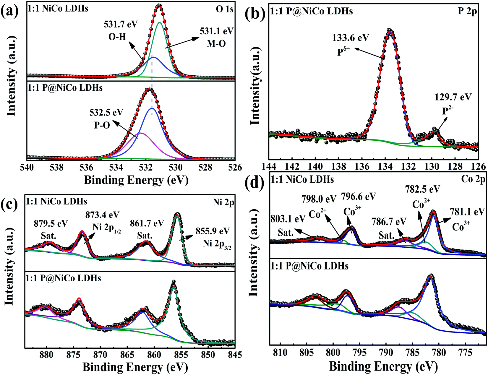
Fig. 2 and Fig. S2 (ESI†) show the XPS results of the full spectra, C 1s, O1s, P 2p, Ni 2p and Co 2p results in 1:1 NiCo LDHs and 1:1 P@NiCo LDHs electrode materials, respectively. Fig. S2a (ESI†) shows the full survey spectrum, in which no other element changes except for the introduction of the P element. All XPS peak positions were corrected based on impurity carbon (284.8 eV), as shown in Fig. S2b (ESI†). As shown in Fig. 2a, the peak located at 531.7 eV and 532.5 eV is usually contributed by oxygen in the OH− group from NiCo LDHs and the metal oxygen bonding, respectively. The peak located at 532.5 eV is assigned to P–O bonds, which are caused by phosphating treatment.19 Importantly, as shown in Fig. 2b, the peak located at 133.6 eV corresponds to Pδ+, and the peak located at 129.7 eV is a typical characteristic of P2−. In the case of Ni 2p shown in Fig. 2c, the characteristic peak located at 873.4 eV and 855.9 eV correspond to Ni2+ and there are two satellite peaks located at 879.5 eV and 861.7 eV, respectively. Therefore, the valence state of the Ni element does not change obviously before and after phosphating. Besides, the peaks located at 798.0 eV and 782.5 eV are attributed to Co2+, and the peaks at 796.6 eV and 781.1 eV are ascribed to Co3+, respectively.32 There are also two satellite peaks located at 803.1 eV and 786.7 eV. Furthermore, the relative content of elements based on XPS analysis is given in Table 1, from which can be concluded that phosphating treatment has little influence on the valence state of elements. The ratio of Co/Ni and Co3+/Co2+ has a slight, but negligible decrease after phosphating treatment, indicating that the bonding element of nickel and cobalt metal is changed from oxygen to phosphorus while its valence state remains. Those XPS results manifest the coexistence of Ni, Co, O and P in the prepared sample, which matches the phase of NiCo LDHs and metal phosphide.
 | ||
| Fig. 2 The XPS spectra of 1:1 NiCo LDHs and 1:1 P@NiCo LDHs: (a) O 1s; (b) P 2p; (c) Ni 2p and (d) Co 2p. | ||
| Samples | C | O | Co2+ | Co3+ | Ni | P | Co/Ni | Co3+/Co2+ |
|---|---|---|---|---|---|---|---|---|
| 1:1 NiCo LDHs |
20.6% | 53.3% | 2.1% | 12.2% | 11.8% | — | 0.83 | 5.8 |
| 1:1 P@NiCo LDHs |
26.1% | 52.4% | 1.5% | 6.6% | 6.0% | 7.4% | 0.74 | 4.7 |
The morphology of the prepared samples was detected by SEM, TEM and HRTEM methods. Fig. 3a and b show the FESEM picture of NiCo LDHs and appear as cabbage-like sphere that are evenly dispersed and stacked. The diameter of the cabbage-like sphere was about 200 nm to 400 nm. It can be seen from the enlarged view in Fig. 3c that the surface of the cabbage-like sphere exhibits the pattern of a lamellar disorderly pile, which potentially contributes to the irregular accumulation of layered metal hydroxides in the reaction process. This stacking form provides a good channel for the transport of electrolyte ions and charge transfer. Interestingly, it can be seen from Fig. 3d that the surface of the sample becomes rough and has some black matter after phosphating treatment, which might be the phosphating compound of nickel or cobalt metal. Moreover, instead of destroying this stacked structure, the phosphating process provides a more conductive phosphide on the surface of samples.
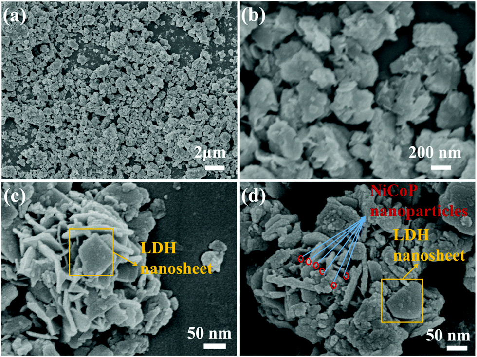 | ||
| Fig. 3 (a) and (b) are FESEM images of NiCo LDHs; (c) enlarged FESEM images of NiCo LDHs; (d) FESEM images of P@NiCo LDHs. | ||
This phenomenon is also shown in TEM and HRTEM. Typically, these cabbage-like sphere samples are about 400 nm in diameter as seen from Fig. 4a, which is consistent with the SEM results. Besides, the high-resolution TEM (HRTEM) image shown in Fig. 4b presents a well-defined lattice fringe with a distance of 0.75 nm, which is the typical (003) plane of the hydrotalcite phase. The SAED image in the inset of Fig. 4b also shows the (009) plane of the hydrotalcite phase. These results further confirmed the successful preparation of hydrotalcite NiCo LDHs. In addition, it can be seen from Fig. 4c that the size of the cabbage-like sphere has no change, and there are obvious granular substances on the surface after the phosphating treatment process. In addition, the HRTEM images were used to prove its structure. As shown in Fig. 4d, the lattice fringes with a distance of about 0.22 nm and 0.4 nm correspond to the (111) plane of NiCoP and the (006) plane of NiCo LDHs, respectively. The signal of NiCoP is also reflected in the SAED image embedded in Fig. 4d. By comparing the morphologies and crystal structures before and after phosphating, it can be concluded that phosphating treatment partially produces bimetallic phosphates and does not destroy the microscopic morphology of the cabbage-like sphere. EDS and element mapping analyses were also used to study the elemental composition and the existence of phosphide in the sample. In the EDS profile of NiCo LDHs in Fig. S3a (ESI†), the clear peaks of O, Co and Ni confirm the homogenous distribution of oxygen, cobalt and nickel presence in the NiCo LDHs sample. Exhilaratingly, the EDS profile of P@NiCo LDHs in Fig. 4e shows the P peak, and the quantitative analysis shows 16.33 At% in the sample. Considering the results of the high-resolution EDX elemental mapping results in Fig. 4f together, the Ni, Co, P and O elements were homogeneously distributed in the P@NiCo LDHs electrode material.
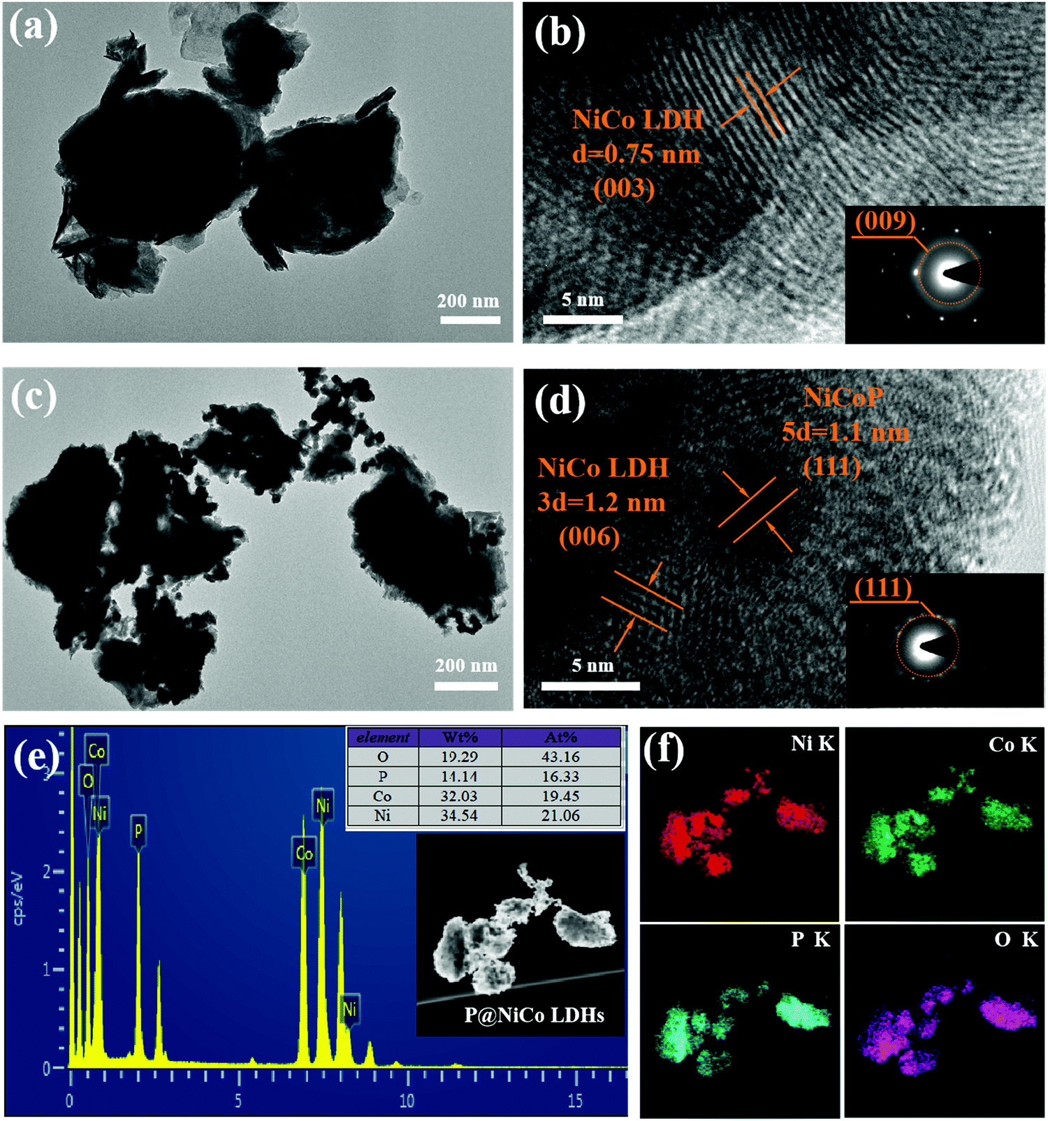 | ||
| Fig. 4 TEM and HRTEM images of (a) and (b) 1:1 NiCo LDHs; (c) and (d) 1:1 P@NiCo LDHs; (e) EDX pattern of the 1:1 P@NiCo LDHs; (f) EDS mapping of Ni, Co, P and O elements on phosphating treated LDHs. | ||
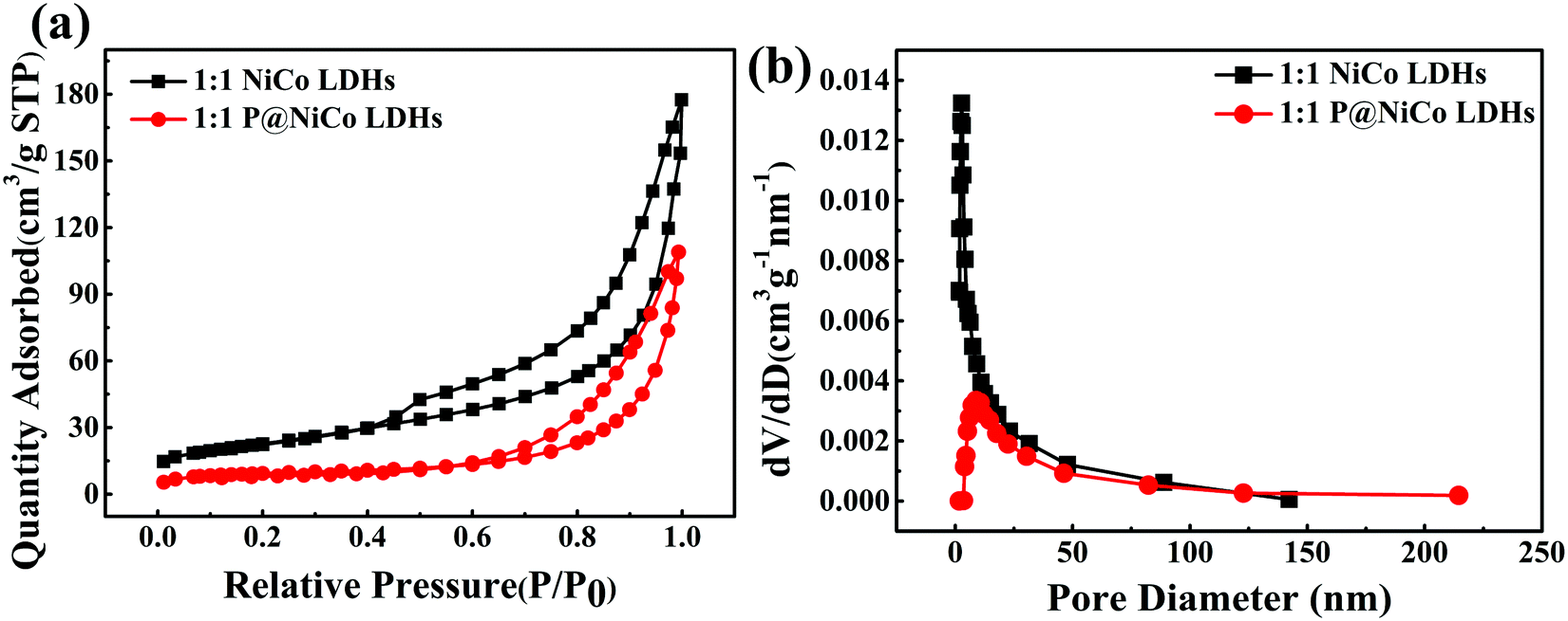
In addition, the average specific surface area of the sample increased from 60.93 m2 g−1 to 80 m2 g−1 after phosphating treatment, as seen from Table S1 (ESI†), which was obtained from N2 adsorption isotherms analysis. It is generally accepted that the larger the specific surface area is, the more favorable it is for the transfer of electrolyte ions and charge. This indicates that the phosphating process has a positive effect on the charge transfer and ion exchange. Besides, the pore size distributions were calculated by the Barrett–Joyner–Halenda (BJH) method based on the N2 adsorption isotherms. For the NiCo LDHs and P@NiCo LDHs samples, the curves are type IV isotherms with H3 typical hysteresis loop, as observed in Fig. 5a, indicating the presence of an accumulation of pores.33,34 The pore size distribution curves in Fig. 5b show that the NiCo LDHs and P@NiCo LDHs mainly consist of a mesoporous structure with an average pore size of 21.79 nm and 13.65 nm (Table S1, ESI†), respectively. This change may be due to the presence of phosphating material on the surface, but the radius of the electrolyte ion (RK+ = 0.133 nm) is much smaller than the pore diameter, so there is almost no effect on its transmission. On the contrary, the phosphating process increased the pore volume from 0.16 to 0.23 cm3 g−1, indicating more ion transport channels and benefitting the charge storage.
 | ||
| Fig. 5 (a) BET adsorption–desorption isotherms of prepared samples; (b) the corresponding pore size distributions. | ||
Based on the above analysis of the morphology and composition of the electrode materials with nickel–cobalt hydrotalcite structure and the phosphating electrode material, it can be seen that the cabbage-like NiCo LDHs sphere was successfully prepared. After the phosphating process, the whole structure was not destroyed. Furthermore, the pore size structure of NiCo LDHs was optimized to improve the specific surface area. These changes are beneficial to the transport of electrolyte ions and charge.
3.2. Three-electrode electrochemical performance of prepared P@NiCo LDHs
Based on the special structure and composition characteristics, we predict that the phosphatized materials have better electrochemical properties than the unphosphatized materials. A standard three-electrode system was utilized to investigate its electrochemical capacitance via CV, GCD and EIS measurements under ambient temperature. Fig. 6a shows the CV curves of P@NiCo LDHs at various scan rates from 5 to 100 mV s−1. There are two obvious redox peaks in the potential range from 0 to 0.5 V, which proved that the P@NiCo LDHs electrode possessed great pseudocapacitive feature and excellent reversibility of the fast charge–discharge response. According to the theoretical description of the voltammetric response of the electroactive materials, the b value can distinguish the pseudocapacitive charge-storage mechanism from that of battery materials. As the b values approach 1, the material exhibits typical capacitance characteristics, while as b values approach 0.5, it exhibits secondary battery characteristics.3,35,36Fig. 6b shows the b values of the charging process (b1) and discharging process (b2), which were calculated by referring to the previous reports.37 It can be seen that the P@NiCo LDHs electrode in aqueous KOH holds a b value of 0.75 and 0.8 for the charging and discharging processes, respectively, confirming the pseudocapacitive behavior of the prepared P@NiCo LHDs electrode.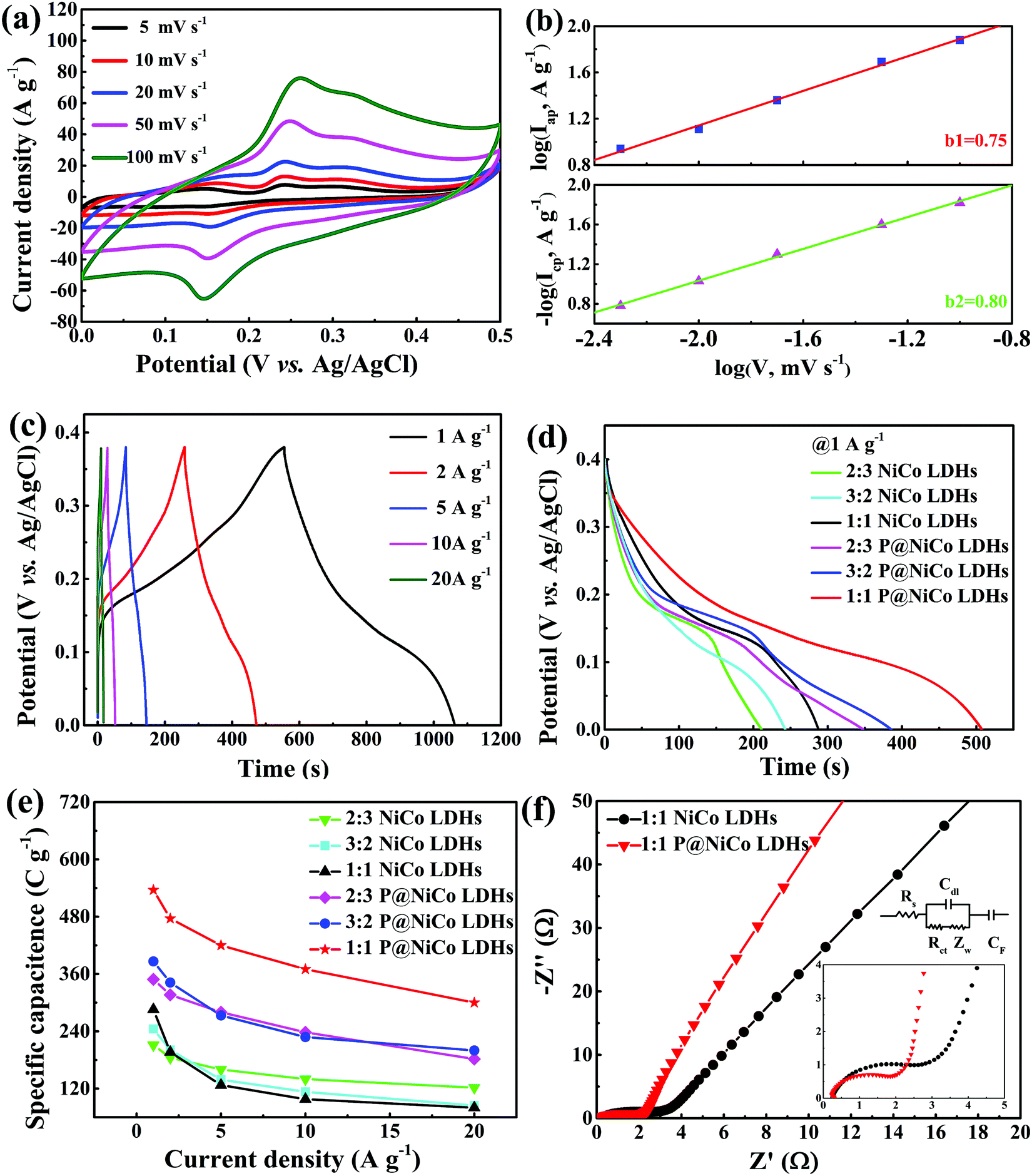 | ||
| Fig. 6 Electrochemical properties of the as-prepared materials in the three-electrode system: (a) CV curves of 1:1 P@NiCo LDHs at various scan voltages; (b) corresponding logIcp and logIapvs. log v; (c) galvanostatic charge−discharge results of the 1:1 P@NiCo LDHs under various current densities; (d) comparison of the galvanostatic charge discharge results (1 A g−1); (e) specific capacitance of different obtained electrodes at various current densities; (f) Nyquist plots of NiCo LDHs and P@NiCo LDHs. | ||
The chronopotentiometry method was utilized to obtain SC values of the P@NiCo LDHs electrode. Fig. 6c shows the typical GCD plots within a wide current density range from 1 to 20 A g−1. The non-linear charge–discharge curves at various current densities show the pseudocapacitive feature, which is consistent with the CV results. Concretely, the discharge curves at 1 A g−1 of different prepared materials are shown in Fig. 6d. It can be seen that the 1:1 P@NiCo LDHs electrode has the longest discharge time, indicating the maximum specific capacity of the corresponding material. Then, the SCs of different prepared materials at various current densities were calculated based on the GCD plot, and the results are shown in Fig. 6e. The 1:1 P@NiCo LDHs electrode also exerts the maximum specific capacity of 536 C g−1 at a current density of 1 A g−1 and 300 C g−1 at a current density of 20 A g−1, and the SC retention is 55.9%. It can be found that after the phosphating treatment, the SCs of the prepared electrodes were about double to that of the corresponding NiCo LDHs, which is due to the high conductivity of the phosphide.30 In addition, the Ni/Co ratio also affected the charge storage capacity of the material. The 1:1 form showed the best ratio to obtain the maximal charge storage capacity.
Besides, the long duration cycling performance of the 1:1 P@NiCo LDHs electrode was conducted at a current density of 10 A g−1. As shown in Fig. S4a (ESI†), the SC and coulombic efficiency show no decline after 5000 charge–discharge cycles, indicating the remarkable and stable supercapacitor performance of the P@NiCo LDHs materials.
To further investigate the electron and ion transport kinetics of the NiCo LDHs and P@NiCo LDHs electrodes, EIS measurements were carried out and the results are shown in Fig. 6f and Fig. S4b (ESI†). Consistent with the previous reports, the impedance spectra of the prepared electrode are composed of one semicircle and a linear segment in the high and low frequency region, respectively.38 The equivalent circuit contains the equivalent series resistance Rs (defined by the intercept at the real axis), double layer capacitance Cdl, the charge-transfer resistance Rct (defined by the diameter of the semicircle), Warburg impedance Zw and pseudocapacitance CF. In detail, the equivalent series resistance (Rs) of the two electrodes have no obvious distinction, as seen from the intercept at the real axis in the magnified area of Fig. 6f. However, the charge-transfer resistance (Rct) of the P@NiCo LDHs electrode was lower than that for the NiCo LDHs electrode, as indicated by the diameter of the semicircle. The decrease of Rct facilitated a rapid charge transfer within the electrode, and between the electrode/electrolyte interface. That is to say, the phosphating treatment reduces the Rct of the electrode material and improves the overall charge storage capacity of the materials. In addition, the ECSAs before and after phosphating were estimated by CV curves in the potential region of the non-Faraday reaction (0–0.1 V), which is shown in Fig. S5a (ESI†). The calculated Cdl is shown in Fig. S5b (ESI†) for comparison, from which, it can be seen that the ECSA has a slight decrease after phosphating treatment. In other words, there is a slight reduction in the number of intrinsic active sites after the phosphating treatment. This difference further indicates that the improvement of electrochemical performance is dominated by the improvement of the electrical conductivity, rather than the change of structure.
Finally, the above electrochemical performances (such as specific capacitance, rate performance and cycling stability) were compared with those of similar materials that were previously reported, which are presented in Table 2. It can be seen that the specific capacitance and cycling characteristics of our P@NiCo LDHs electrode material are superior to most of the LDH-based materials listed in Table 1, while the rate performance is slightly worse. To sum up, the P@NiCo LDHs electrode material with good properties were prepared by a simple method, which provides an approach for the preparation of supercapacitors electrode.
| Electrode materials | Specific capacitance | Capacitance retention | Cycling stability (cycles) | Ref. |
|---|---|---|---|---|
| Flower NiCo LDHs | 1187.2 F g−1 (1 A g−1) | 71% (30 A g−1) | 97% (1000) | 39 |
| MnO2 nanotubes @NiCoLDH/CoS2 nanocages | 1547 F g−1 (1 A g−1) | 76.9% (10 A g−1) | 82.3% (2000) | 40 |
| NiCoP/NiCo-OH 3D | 1100 F g−1 (1 A g−1) | 60% (10 A g−1) | 88% (1000) | 20 |
| KCu7S4@NiCoLDH | 1104.5 F g−1 (2 A g−1) | 65.9% (10 A g−1) | 83.5% (1000) | 41 |
| NiAl LDH hollow microspheres | 1578 F g−1 (1 A g−1) | 56% (20 A g−1) | 93.75% (10000) |
42 |
| NiAl–LDH nanosheet/graphene | 1329 F g−1 (3.57 A g−1) | 64.03% (17.86 A g−1) | 91% (500) | 43 |
| core–shell Ag nanowire@NiAl LDH | 1148 F g−1 (1 A g−1) | 63.4% (10 A g−1) | 77.2% (10000) |
44 |
| sandwich-like CoAl-LDH/polypyrrole/graphene | 864 F g−1 (1 A g−1) | 75% (20 A g−1) | No loss (5000) | 45 |
| Ni3Mn1-LDH@Ni foam | 1511 F g−1 (2.5 A g−1) | 80.1% (48 A g−1) | 97.2% (3000) | 46 |
| CoMn LDH nanowires | 1409 F g−1 (1 A g−1) | 71.1% (10 A g−1) | 93.2% (3000) | 47 |
| CoNi-LDH thin sheets | 394.5 C g−1 | 54.4% (10 A g−1) | 92.3% (10000) |
48 |
| Co0.5Ni0.5WO4 | 626.4 C g−1 | 65.3% (8 A g−1) | 105.3% (10000) |
49 |
| P@NiCo LDHs | 1340 F g−1 536 C g−1 (1 A g−1) | 55.9% (20 A g−1) | Rarely decrease (5000) | This work |
3.3. Electrochemical performance of P@NiCo LDHs//P@NiCo LDHs symmetric supercapacitor
To study the practical application of the obtained cabbage-like sphere materials, the symmetric supercapacitor device was prepared. The electrochemical properties of this device were also conducted on an electrochemical workstation. Fig. 7 shows the property results of the device. In detail, Fig. 7a shows a simple model to describe the fabrication process of the P@NiCo LDHs//P@NiCo LDHs symmetric supercapacitor device. Nickel foam was the current collector of the device, and the prepared P@NiCo LDHs on both sides of the PBI-KOH membrane act as the positive and negative electrode materials. Fig. 7b shows the CV curves of the device at different potential windows at 20 mV s−1 scan rate. When the potential window increases from 0.8 V to 1.2 V, the whole curves have a good rectangular shape, indicating that the device has a good capacitance performance. When the potential window is 1.3 V, the curve appears abnormal, which may be due to the evolution of oxygen changes in the internal structure, thus limiting the charge storage. Thus, 1.2 V was determined to be the working potential window. Fig. 7c shows the CV curves of the symmetric supercapacitor device under the sweep rate increases from 5 to 200 mV s−1. One can see that the curve exerts a near-rectangle shape, which implies the ideal reversibility and stability.50 As shown in Fig. 7d, the specific capacity can reach 39.17 F g−1 at 0.5 A g−1 and reserves 20.83 F·g−1 at 10 A g−1. Fig. 7e reflects the stability and Coulombic efficiency of the device. After 5000 cycles at 2 A g−1, the capacitance has no significant decrease and the Coulombic efficiency can be maintained around 100%. The Nyquist plots before and after cycles are presented in Fig. S6 (ESI†), and the subtle impedance variations once again demonstrate good stability of this symmetric supercapacitor device. In addition, the Ragone plots between the energy and power densities of the symmetric supercapacitor device are shown in Fig. 7f. The energy density of the device can achieve about 7.8 W h kg−1 at the power density of 300 W kg−1, and it can retain 4.1 W h kg−1 at the high power density of 6000 W kg−1.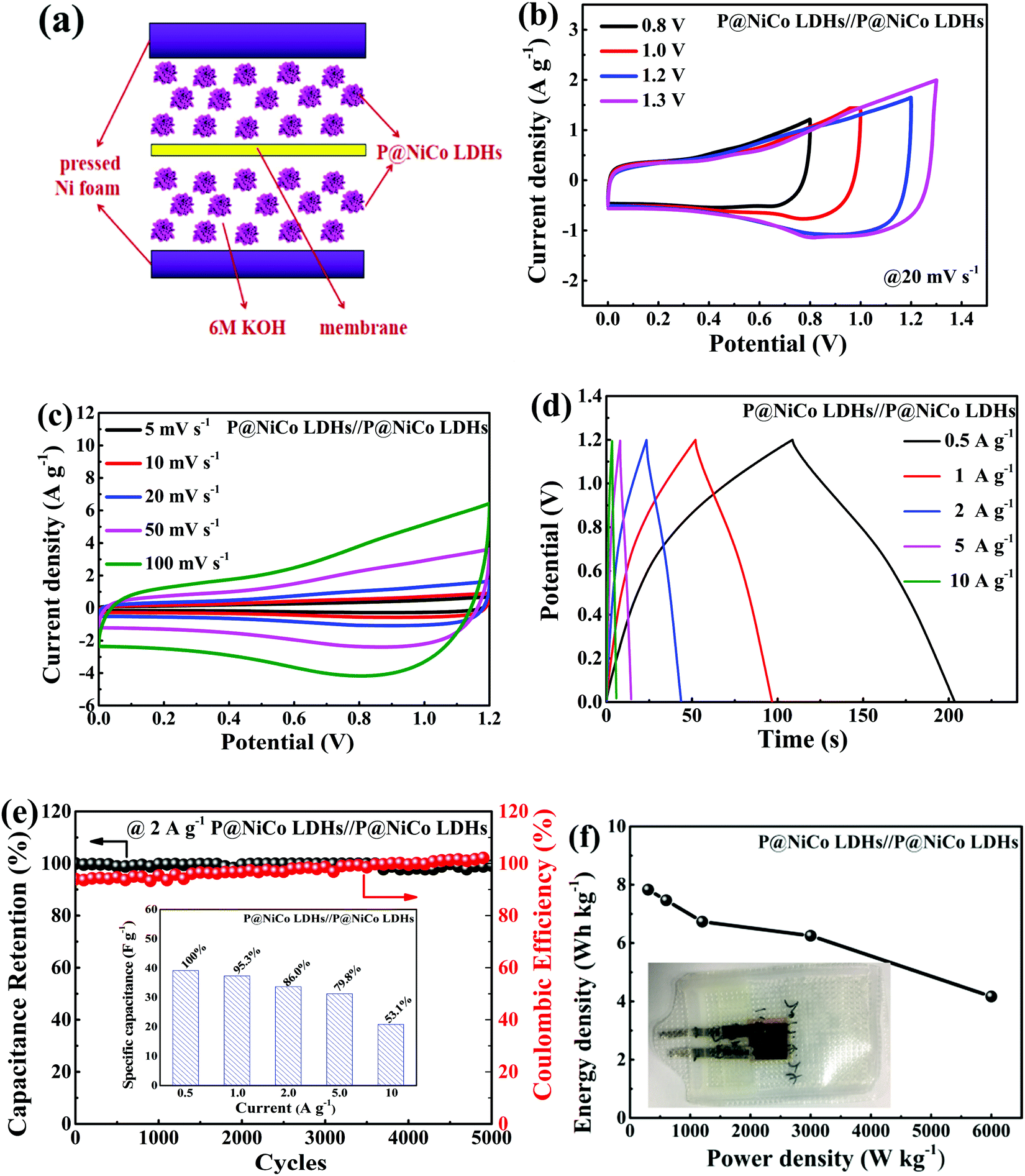 | ||
| Fig. 7 Electrochemical properties of the P@NiCo LDHs//P@NiCo LDHs symmetric supercapacitor device: (a) The simple model and the physical photos of the device; (b) CV curves of the device at different potential windows (0.8–1.3 V); (c) CV curves of the device at various scan voltages; (d) galvanostatic charge−discharge results of the device under various current densities; (e) capacitance retention and coulombic efficiency at the current density of 2 A g−1 and the specific capacitance of the device; (f) Ragone plot related to energy densities and power densities. | ||
4. Conclusions
Based on the above results, P@NiCo LDHs electrode materials have been prepared using a mild hydrothermal reaction and phosphorization treatment. The P@NiCo LDHs electrode material shows better specific capacitance than NiCo LDHs and has good cycling stability, owing to the special layered structure and further phosphating. In addition, the vacuum plastic package symmetrical supercapacitor devices display high energy density and power density, demonstrating that the phosphating treatment is an effective strategy to improve the capacitance of the hydrotalcite-like structural materials.Author contributions
Guorong Wang conceived and designed the experiments; Tiansheng Zhao and Zhiliang Jin performed the experiments and contributed reagents/materials, Guorong Wang wrote the paper, Yanbing Li helped to revise the paper.Conflicts of interest
The authors declare no competing interests.Acknowledgements
The authors thank the financial support from the National Natural Science Foundation of China (No. 22062001), the Natural Science Foundation of Ningxia Province (2020AAC03209, 2020AAC02026) and the Open Project of State Key Laboratory of High-efficiency Utilization of Coal and Green Chemical Engineering, Ningxia University (2019-KF-36).References
- X. J. Li, D. F. Du, Y. Zhang, W. Xing, Q. Z. Xue and Z. F. Yan, Layered double hydroxides toward high-performance supercapacitors, J. Mater. Chem. A, 2017, 5, 15460–15485 RSC
.
- S. Chu and A. Majumdar, Opportunities and challenges for a sustainable energy future, Nature, 2012, 488, 294–303 CrossRef CAS
- Y. L. Shao, M. F. El-Kady, S. Jingyu, Y. G. Li, Q. H. Zhang, M. F. Zhu, H. Z. Wang, B. Dunn and R. B. Kaner, Design and mechanisms of asymmetric supercapacitors, Chem. Rev., 2018, 118, 9233–9280 CrossRef CAS
- J. B. Goodenough and K. S. Park, The Li-Ion rechargeable battery: a perspective, J. Am. Chem. Soc., 2013, 135, 1167–1176 CrossRef CAS
- D. P. Dubal, O. Ayyad, V. Ruiz and P. Gómez-Romero, Hybrid energy storage: the merging of battery and supercapacitor chemistries, Chem. Soc. Rev., 2015, 44, 1777–1790 RSC
- D. C. Lin, Y. Y. Liu and Y. Cui, Reviving the lithium metal anode for high-energy batteries, Nat. Nanotechnol., 2017, 12, 194–206 CrossRef CAS
- M. Winter, B. Barnett and K. Xu, Before Li ion batteries, Chem. Rev., 2018, 118, 11433–11456 CrossRef CAS
- X. Zhao, L. Mao, Q. H. Cheng, J. Li, F. F. Liao, G. Y. Yang, L. Xie, C. L. Zhao and L. Y. Chen, Two-dimensional Spinel Structured Co-based Materials for High Performance Supercapacitors: A Critical Review, Chem. Eng. J., 2020, 387, 124081 CrossRef CAS
- G. P. Wang, L. Zhang and J. J. Zhang, A review of electrode materials for electrochemical supercapacitors, Chem. Soc. Rev., 2012, 41, 797–828 RSC
- L. Q. Mai, F. Yang, Y. L. Zhao, L. L. Xu and Z. Yan, Hierarchical MnMoO4 CoMoO4 heterostructured nanowires with enhanced supercapacitor performance, Nat. Commun., 2011, 2, 381–385 CrossRef
- H. Chen, L. F. Hu, M. Chen and Y. Yan, Nickel cobalt layered double hydroxide nanosheets for high-performance supercapacitor electrode materials, Adv. Funct. Mater., 2014, 24, 934–942 CrossRef CAS
- Y. M. He, W. J. Chen, X. D. Li, Z. X. Zhang, J. C. Fu, C. H. Zhao and E. Q. Xie, Freestanding three-dimensional graphene/MnO2 composite networks as ultra light and flexible supercapacitor electrodes, ACS Nano, 2013, 7, 174–182 CrossRef CAS
- C. Zhou, Y. W. Zhang, Y. Y. Li and J. P. Liu, Construction of high-capacitance 3D CoO@Polypyrrole nanowire array electrode for aqueous asymmetric supercapacitor, Nano Lett., 2013, 13, 2078–2085 CrossRef CAS
- L. H. Bao, J. F. Zang and X. D. Li, Flexible Zn2SnO4/MnO2 core/Shell nanocable-carbon microfiber hybrid composites for high-performance supercapacitor electrodes, Nano Lett., 2011, 11, 1215–1220 CrossRef CAS
- T. Li, G. H. Li, H. Li, L. Liu, Y. Xu, H. Y. Ding and T. Zhang, Large-scale self-assembly of 3D flower-like hierarchical Ni/Co-LDHs microspheres for high-performance flexible asymmetric supercapacitors, ACS Appl. Mater. Interfaces, 2016, 8, 2562–2572 CrossRef CAS
- S. Tonda, S. Kumar, M. Bhardwaj, P. Yadav and S. Ogale, g-C3N4 NiAl-LDH 2D/2D hybrid heterojunction for high-performance photocatalytic reduction of CO2 into renewable fuels, ACS Appl. Mater. Interfaces, 2017, 10, 2667–2678 CrossRef
- J. B. Han, Y. B. Dou, J. W. Zhao, M. Wei, D. G. Evans and X. Duan, Flexible CoAl LDH@PEDOT core/shell nanoplatelet array for high-performance energy storage, Small, 2013, 9, 98–106 CrossRef CAS
- W. W. Zheng, S.
G. Sun, Y. Q. Xu, R. J. Yu and H. J. Li, Facile synthesis of NiAl-LDH/MnO2 and NiFe-LDH/MnO2 composites for high-performance asymmetric supercapacitors, J. Alloys Compd., 2018, 768, 240–248 CrossRef CAS
- X. Li, A. M. Elshahawy, C. Guan and J. Wamg, Metal phosphides and phosphates based electrodes for electrochemical supercapacitors, Small, 2017, 13, 1701530 CrossRef
- X. Li, H. Wu, A. M. Elshahawy, L. Wang, S. J. Pennycook, C. Guan and J. Wang, Cactus-Like NiCoP/NiCo-OH 3D Architecture with Tunable Composition for High-Performance Electrochemical Capacitors, Adv. Funct. Mater., 2018, 28, 1800036 CrossRef
- Q. Q. Qin, J. Q. Liu, W. P. Mao, C. X. Xu, B. B. Lan, Y. Wang, Y. Zhang, J. Yan and Y. C. Wu, Ni(OH)2/CNTs hierarchical spheres for foldable all-solid-state supercapacitor with high specific energy, Nanoscale, 2018, 10, 7377–7381 RSC
- H. B. Li, M. H. Yu, F. X. Wang, P. Liu, Y. Liang, J. Xiao, C. X. Wang, Y. X. Tong and G. W. Yang, Amorphous nickel hydroxide nanospheres with ultrahigh capacitance and energy density as electrochemical pseudocapacitor materials, Nat. Commun., 2013, 4, 1894 CrossRef CAS
- D. Sarkar, G. G. Khan, A. K. Singh and K. Mandal, High-performance pseudocapacitor electrodes based on α-Fe2O3/MnO2 core-shell nanowire heterostructure arrays, J. Phys. Chem. C, 2013, 117, 15523–15531 CrossRef CAS
- Z. Y. Zhang, S. S. Liu, J. Xiao and S. Wang, Fiber-based multifunctional nickel phosphide electrodes for flexible energy conversion and storage, J. Mater. Chem. A, 2016, 4, 9691–9699 RSC
- T. Yan, R. Y. Li, R. Y. Li, Q. Ning, H. Kong, Y. L. Niu and J. K. Liu, Nickel–cobalt double hydroxides microspheres with hollow interiorand hedgehog-like exterior structures for supercapacitors, J. Mater. Chem., 2012, 22, 23587–23592 RSC
- S. J. Ma, L. N. Wang, S. G. Zhang, H. N. Jin, M. Wan, Y. Pan, T. Zhang, Y. K. Wen, M. Zhang, H. Zhu and M. L. Du, Facile fabrication of a binary NiCo phosphide with hierarchical architecture for efficient hydrogen evolution reactions, Int. J. Hydrogen Energy, 2019, 44, 4188–4196 CrossRef CAS
- J. L. Xing, J. Du, X. Zhang, Y. B. Shao, T. Zhang and C. L. Xu, A Ni-P@NiCo LDH core-shell nanorod-decorated nickel foam with enhanced areal specific capacitance for high-performance supercapacitors, Dalton Trans., 2017, 46, 10064–10072 RSC
- S. Tian, X. Li, A. J. Wang, R. Prins, Y. Y. Chen and Y. K. Hu, Facile preparation of Ni2P with a sulfur-containing surface layer by low-temperature reduction of Ni2P2S6, Angew. Chem., Int. Ed., 2016, 55, 4030–4034 CrossRef CAS
- H. N. Jia, Z. Y. Wang, X. H. Zheng, J. H. Lin, H. Y. Liang, Y. F. Cai, J. L. Qi, J. Cao, J. C. Feng and W. D. Fei, Interlaced Ni-Co LDH nanosheets wrapped Co9S8 nanotube with hierarchical structure toward high performance supercapacitors, Chem. Eng. J., 2018, 351, 348–355 CrossRef CAS
- X. Li, A. M. Elshahawy, C. Guan and J. Wang, Metal phosphides and phosphates-based electrodes for electrochemical supercapacitors, Small, 2017, 13, 1701530 CrossRef
- Z. X. Yan, Z. H. Xu, L. Yue, L. Shi and L. Y. Huang, Hierarchical Ni–Al hydrotalcite supported Pt catalyst for efficient catalytic oxidation of formaldehyde at room temperature, Chin. J. Catal., 2018, 39, 1919–1928 CrossRef CAS
- J. K. Zhu, D. M. Song, T. Pu, J. Li, B. Huang, W. S. Wang, C. L. Zhao, L. Xie and L. Y. Chen, Two-dimensional porous ZnCo2O4 thin sheets assembled by 3D nanoflake array with enhanced performance for aqueous asymmetric supercapacitor, Chem. Eng. J., 2018, 336, 679–689 CrossRef CAS
- X. Q. Hao, Z. L. Jin, H. Yang, G. X. Lu and Y. P. Bi, Peculiar synergetic effect of MoS2 quantum dots and graphene on Metal-Organic frameworks for photocatalytic hydrogen evolution, Appl. Catal., B, 2017, 210, 45–56 CrossRef CAS
- H. Yang, Z. L. Jin, H. Y. Hu, Y. P. Bi and G. X. Lu, Ni–Mo–S nanoparticles modified graphitic C3N4 for efficient hydrogen evolution, Appl. Surf. Sci., 2018, 427, 587–597 CrossRef CAS
- S. Y. Dong, L. F. Shen, H. S. Li, P. Nie, Y. Y. Zhu, Q. Shen and X. G. Zhang, Pseudocapacitive behaviours of Na2Ti3O7@CNT coaxial nanocables for high-performance sodium-ion capacitors, J. Mater. Chem. A, 2015, 3, 21277–21283 RSC
- X. L. Dong, L. Chen, J. Y. Liu, S. Haller, Y. G. Wang and Y. Y. Xia, Environmentally-friendly aqueous Li (or Na)-ion battery with fast electrode kinetics and super-long life, Sci. Adv., 2016, 2, e150103 Search PubMed
- L. R. Hou, Y. Y. Shi, S. Q. Zhu, M. Rehan, G. Pang, X. G. Zhang and C. Z. Yuan, Hollow mesoporous hetero-NiCo2S4/Co9S8 submicro-spindles: unusual formation and excellent pseudocapacitance towards hybrid supercapacitors, J. Mater. Chem. A, 2017, 5, 133–144 RSC
- J. Y. Ji, L. L. Zhang, H. X. Ji, Y. Li, X. Zhao, X. Bai, X. B. Fan, F. B. Zhang and R. S. Ruoff, Nanoporous Ni(OH)2 thin film on 3D ultrathin-graphite foam for asymmetric supercapacitor, ACS Nano, 2013, 7, 6237–6243 CrossRef CAS
- Y. P. Zhou, J. Li, Y. Yang, B. Luo, X. Zhang, E. Fong, W. Chu and K. Huang, Unique 3D flower-on-sheet nanostructure of NiCo LDHs: Controllable microwave-assisted synthesis and its application for advanced supercapacitors, J. Alloys Compd., 2019, 788, 1029–1036 CrossRef CAS
- X. H. Wang, F. F. Huang, F. Rong, P. He, R. H. Que and S. P. Jiang, Unique MOF-derived hierarchical MnO2 nanotubes@NiCo-LDH/CoS2 nanocages materials as high performance supercapacitor, J. Mater. Chem. A, 2019, 7, 12018–12028 RSC
- P. Yang, C. Jing, J. C. Liu, K. Chen and Y. X. Zhang, Controllable crystal growth of a NiCo-LDH nanostructure anchored onto KCu7S4 nanowires via a facile solvothermal method for supercapacitor application, CrystEngComm, 2020, 22, 1602–1609 RSC
- W. C. Wang, N. Zhang, Z. Y. Shi, Z. R. Ye, Q. Y. Gao, M. J. Zhi and Z. L. Hong, Preparation of Ni–Al layered double hydroxide hollow microspheres for supercapacitor electrode, Chem. Eng. J., 2018, 338, 55–61 CrossRef CAS
- J. Xu, S. L. Gai, F. He, N. Niu, P. Gao, Y. J. Chen and P. P. Yang, A sandwich-type three-dimensional layered double hydroxide nanosheet array/graphene composite: fabrication and high supercapacitor performance, J. Mater. Chem. A, 2014, 2, 1022–1031 RSC
- L. Li, K. S. Hui, K. N. Hui, T. F. Zhang, J. J. Fu and Y. R. Cho, High-performance solid-state flexible supercapacitor based on reduced graphene oxide/hierarchical core-shell Ag nanowire@NiAl layered double hydroxide film electrode, Chem. Eng. J., 2018, 348, 338–349 CrossRef CAS
- Y. Zhang, D. F. Du, X. J. Li, H. M. Sun, L. Li, P. Bai, W. Xing, Q. Z. Xue and Z. F. Yan, Electrostatic self-assembly of sandwich-like CoAl-LDH/polypyrrole/graphene nanocomposites with enhanced capacitive performance, ACS Appl. Mater. Interfaces, 2017, 9, 31699–31709 CrossRef CAS
- X. L. Guo, X. Y. Liu, X. D. Hao, S. J. Zhu, F. Dong, Z. Q. Wen and Y. X. Zhang, Nickel-Manganese Layered Double Hydroxide Nanosheets Supported on Nickel Foam for High-performance Supercapacitor Electrode Materials, Electrochim. Acta, 2016, 194, 179–186 CrossRef CAS
- D. M. Chen, H. Y. Chen, X. Chang, P. Liu, Z. C. Zhao, J. W. Zhou, G. W. Xu, H. L. Lin and S. Han, Hierarchical CoMn-layered double hydroxide nanowires on nickel foam as electrode material for high-capacitance supercapacitor, J. Alloys Compd., 2017, 729, 866–873 CrossRef CAS
- B. Huang, W. S. Wang, T. Pu, J. Li, J. K. Zhu, C. L. Zhao, L. Xie and L. Y. Chen, Two-dimensional porous (Co, Ni)-based monometallic hydroxides and bimetallic layered double hydroxides thin sheets with honeycomb-like nanostructure as positive electrode for high-performance hybrid supercapacitors, J. Colloid Interface Sci., 2018, 532, 630–640 CrossRef CAS
- B. Huang, H. Y. Wang, S. F. Liang, H. Z. Qin, Y. Li, Z. Y. Luo, C. L. Zhao, L. Xie and L. Y. Chen, Two-dimensional porous cobalt-nickel tungstate thin sheets for high performance supercapattery, Energy Storage Mater., 2020, 32, 105–114 CrossRef
- H. P. Lv, Y. Yuan, Q. J. Xu, H. M. Liu, Y. G. Wang and Y. Y. Xia, Carbon quantum dots anchoring MnO2/graphene aerogel exhibits excellent performance as electrode materials for supercapacitor, J. Power Sources, 2018, 398, 167–174 CrossRef CAS
Footnote |
| † Electronic supplementary information (ESI) available: Partial results can be found in the supporting information. See DOI: 10.1039/d0nj03070h |
| This journal is © The Royal Society of Chemistry and the Centre National de la Recherche Scientifique 2021 |