 Open Access Article
Two-dimensional graphitic carbon nitride/N-doped carbon with a direct Z-scheme heterojunction for photocatalytic generation of hydrogen†
Jing
Wang‡
 a,
Youcai
Sun‡
a,
Jianwei
Lai
b,
Runhui
Pan
a,
Yulei
Fan
a,
Xiongwei
Wu
a,
Youcai
Sun‡
a,
Jianwei
Lai
b,
Runhui
Pan
a,
Yulei
Fan
a,
Xiongwei
Wu
 c,
Man
Ou
 a,
Yusong
Zhu
a,
Lijun
Fu
a,
Yusong
Zhu
a,
Lijun
Fu
 a,
Feifei
Shi
*b and
Yuping
Wu
 *a
*a
aCollege of Chemical Engineering, School of Energy Science and Engineering, Nanjing Tech University, Nanjing, Jiangsu 211816, China. E-mail: wuyp@njtech.edu.cn
bJohn and Willie Leone Family Department of Energy and Mineral Engineering, Pennsylvania State University, University Park, PA 16802, USA. E-mail: feifeishi@psu.edu
cSchool of Chemistry and Materials Science, Hunan Agricultural University, Changsha, 410128, China
First published on 4th October 2021
Abstract
Photocatalysts with a direct Z-scheme heterojunction are promising by virtue of the effectively enhanced separation of charge carriers, high retention of redox ability and the absence of backward photocatalytic reactions. Their activity depends on band alignment and interfacial configurations between two semiconductors for charge carrier kinetics and the effective active sites for photochemical reactions. Herein, a two-dimensional (2D) graphitic carbon nitride/N-doped carbon (C3N4/NC) photocatalyst is synthesized by a gas template (NH4Cl)-assisted thermal condensation method. C3N4/NC has the synthetic merits of a direct Z-scheme heterojunction, 2D–2D interfacial contact, and enhanced specific surface area to improve charge separation kinetics and provide abundant active sites for photochemical reaction. It exhibits an over 46-fold increase of the photocatalytic hydrogen production rate compared to bulk C3N4 under visible light illumination. This work demonstrates the great potential of 2D Z-scheme heterojunctions for photocatalysis and will inspire more related work in the future.
To effectively address sustainable energy and environmental issues, the conversion from solar energy to hydrogen production is regarded as a promising and pollution-free approach, which is achieved by photocatalytic technology.1–5 Since the pioneering discovery of water splitting by Fujishima in 1972, numerous semiconductors (e.g., TiO2, α-Fe2O3, CdS, Cu2O, and BiVO4) have been widely studied in photocatalysis.6–9 However, challenges still exist in improving the separation rate of photogenerated electron–hole pairs in photocatalysts to enhance the activity of water splitting.10,11 To overcome these drawbacks, the heterojunction strategy has been employed as a practical approach for improving charge carrier separation efficiency and photocatalytic activity.12,13
According to the band alignment of two semiconductors, there are three types of heterojunctions (Fig. 1): type I (straddling gap), type II (staggered gap), and type III (broken gap).14,15 Both electrons and holes are predominantly transferred on the surface of photocatalyst II in the type I heterojunction, which is not suitable for charge carrier separation; it is energetically unfavorable for charge carrier transfer in the type III heterojunction. For the type II heterojunction, the photogenerated electrons easily transfer from the high conduction band (CB) to low CB, while the holes transfer from the low valence band (VB) to high VB, which can promote the spatial separation of charge carriers and then improve the photocatalytic performance.14 However, two semiconductors with a similar staggered gap might present different processes of photoinduced charge carrier transfer, which resembles the letter “Z” and is defined as a Z-scheme heterojunction.16,17 As described in Fig. 1a–c, depending on the involvement of electron mediators, a Z-scheme heterojunction can be classified as traditional Z-scheme (redox-pair mediator),16 all-solid-state Z-scheme (solid mediator),18 and direct Z-scheme (no mediator).12 It should be noted that a direct Z-scheme heterojunction can avoid the selection and shielding effect of electron mediators as well as the backward photochemical reactions. Furthermore, the unique “Z” shape transport pathway of charge carriers (Fig. 1c, red box) allows the electrons with lower reduction ability preferentially recombine with the holes with lower oxidation ability, while the electrons with higher reduction ability and holes with higher oxidation ability remain in their corresponding CB and VB.19,20 Therefore, a direct Z-scheme heterojunction is highly desired for efficient photocatalysis since it provides a promising pathway for improving charge carrier transfer kinetics, highly preserving redox ability, and avoiding the backward photocatalytic reactions.
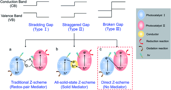 | ||
| Fig. 1 Schematic illustration of different heterojunctions. (a) Traditional Z-scheme; (b) all-solid-state Z-scheme; (c) direct Z-scheme. | ||
The selection of suitable semiconductors is a prerequisite for constructing a practical direct Z-scheme heterojunction.21 To date, metal-based semiconductors are widely studied for H2 production.1 However, severe metal leaching in metal-based photocatalysts will cause detrimental environmental pollution and thus greatly limit their large-scale applications. Therefore, the investigations of metal-free photocatalysts have received increasing attention.22 Graphitic carbon nitride (C3N4) as a promising metal-free photocatalyst shows great potential for photocatalytic H2 generation, which is attributed to the 2D structure, suitable bandgap, high stability, tunable structure, and low cost.23–26 However, the pure/bulk C3N4 suffers from a slow rate of photoinduced charge carrier separation.27 The heterojunction strategy, pairing C3N4 with a proper semiconductor, can be utilized to overcome the above mentioned disadvantages.28,29 Yet the performance improvement is achieved at the expense of environmental pollution caused by metal leaching. N-doped carbon (NC), a metal-free material, is a promising coupling component for 2D heterojunctions due to its intrinsic characteristics of excellent electrical conductivity, a tunable band, and a matchable 2D structure with C3N4.30–33 Furthermore, the π–π stacking interaction between C3N4 and NC will enhance the charge carrier separation at the interface.34 Therefore, the construction of 2D C3N4/NC photocatalysts with a direct Z-scheme heterojunction is highly desired yet challenging, and it is also necessary to fully explore and understand the corresponding mechanism.
In the presented work, the 2D direct Z-scheme C3N4/NC photocatalysts exhibit remarkably enhanced photocatalytic activity. The manipulation of a direct Z-scheme heterojunction is achieved through the suitable staggered band structure and the π–π stacking interaction between C3N4 and NC, which endows C3N4/NC with a higher charge carrier separation rate and stronger redox ability. Besides, the 2D–2D structure of C3N4/NC results in a high specific surface area and large interfacial contact, which promotes fast charge carrier transfer and redox reactions. As a result, the synthesized 2D direct Z-scheme C3N4/NC photocatalysts show a remarkably enhanced visible-light-driven H2 evolution rate of 3.060 mmol h−1 g−1, which is over 46 times that of bulk C3N4. The fundamental mechanism of improved photocatalytic activity is also discussed in detail. This work may provide new perspectives on the rational design of 2D heterojunction materials with a direct Z-scheme mechanism.
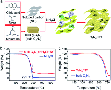
The general fabrication process of C3N4/NC photocatalysts is illustrated in Fig. 2a, and the preparation details are provided in the experimental section. First, NC was prepared via a facile hydrothermal method, and bulk C3N4 was synthesized through the polymerization of melamine. Then, C3N4/NC photocatalysts were obtained by calcining a mixture of NC, bulk C3N4, and NH4Cl. During the annealing process, NH4Cl as a gas template will be decomposed and release NH3 and HCl. These released gases can drive the formation of pores and exfoliate the stacked sheets of the bulk carbon nitride simultaneously.35 By regulating the mass ratio of NC in C3N4/NC, three different samples of C3N4/NC-I, C3N4/NC-II, and C3N4/NC-III were prepared with the corresponding mass ratios of 0.05%, 0.075%, and 0.10%. The optimal C3N4/NC-II exhibits the best photocatalytic performance and is denoted as C3N4/NC unless otherwise stated. To understand the formation mechanism of C3N4/NC, thermogravimetric (TG) analysis was carried out. As presented in Fig. 2b, the NH4Cl gas template in the mixture of bulk C3N4, NH4Cl, and NC, is fully decomposed into NH3 and HCl at 295 °C, and the combustion of NC is observed from 250 °C to 520 °C.36Fig. 2c illustrates the improved thermal stability of C3N4/NC over bulk C3N4.
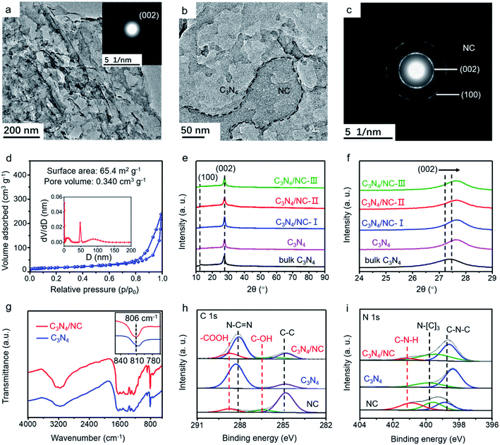
The morphology of as-synthesized bulk C3N4, C3N4, and C3N4/NC was studied by transmission electron microscopy (TEM). Bulk C3N4 shows a dense layer-stacking feature (Fig. S1a†), while C3N4 presents 2D sheets (Fig. 3a). The distinct morphology difference confirms the efficient exfoliation of C3N4. For crystalline C3N4/NC, NC sheets with small pores are attached to the C3N4 sheets (Fig. 3b and c), and they obviously increase with the NC mass ratios in photocatalysts (Fig. S1†). The simultaneous formation of thin C3N4 sheets and numerous pores is attributed to the introduction of the NH4Cl gas template. Based on the Brunauer–Emmett–Teller (BET) theory, the specific surface area and the pore volume are fully investigated. As shown in Fig. 3d, the optimized C3N4/NC has a significantly higher surface area of 65.4 m2 g−1 and pore volume of 0.340 cm3 g−1 compared to the bulk C3N4 and C3N4 (Fig. S2†). The crystal structures of the as-prepared samples are characterized by X-ray diffraction (XRD), as displayed in Fig. 3e. Two characteristic peaks at 13° and 27° can be well indexed to C3N4, which corresponds to peaks (100) and (002); (100) reflects the in-plane structural packing motif peak, and (002) represents the interplanar stacking of the conjugated aromatic system.37 The peaks of the (002) plane slightly shifting towards a higher degree is also observed in Fig. 3f, which corresponds to the reduction of the stacking distance after an NH4Cl blowing procedure at high temperature.38
Fourier transform infrared spectroscopy (FTIR) and X-ray photoelectron spectroscopy (XPS) are employed to investigate the local chemical composition and states of C3N4 and C3N4/NC. In the FTIR spectra, the peaks located between 1200 and 1700 cm−1 are ascribed to the CN heterocycle stretching modes (Fig. 3g).39,40 The broad peaks at 2800–3400 cm−1 correspond to the O–H and N–H stretching vibrations, which indicates the presence of surface hydroxyl and amino groups.36,41 The sharp peak at 806 cm−1 represents the characteristic breathing mode of the tri-s-triazine units.42 The FTIR profiles of C3N4 and C3N4/NC are very similar, suggesting that the introduction of NC barely changes the basic structure of C3N4. However, it should be noted that there is a slight peak shift for C3N4/NC at around 810 cm−1, which may result from the interaction between C3N4 and NC.43
XPS results of C3N4/NC, C3N4, and NC are collected to investigate the specific interaction between C3N4 and NC. For C3N4, the XPS C 1s spectrum is divided into C–C (284.8 eV) and N–C![[double bond, length as m-dash]](https://www.rsc.org/images/entities/char_e001.gif) N (287.9 eV), and the N 1s spectrum is split into two peaks at 398.4 and 399.9 eV, which are attributed to sp2-hybridized nitrogen (C–N
N (287.9 eV), and the N 1s spectrum is split into two peaks at 398.4 and 399.9 eV, which are attributed to sp2-hybridized nitrogen (C–N![[double bond, length as m-dash]](https://www.rsc.org/images/entities/char_e001.gif) C) and sp3-hybridized nitrogen (N–[C]3), respectively (Fig. 3h and i).43–47 A noticeable new peak at 289.3 eV is observed for C3N4/NC, which originates from –COOH of NC. Notably, the peak shift of N–C
C) and sp3-hybridized nitrogen (N–[C]3), respectively (Fig. 3h and i).43–47 A noticeable new peak at 289.3 eV is observed for C3N4/NC, which originates from –COOH of NC. Notably, the peak shift of N–C![[double bond, length as m-dash]](https://www.rsc.org/images/entities/char_e001.gif) N towards higher binding energy in C3N4/NC results from the π–π stacking interaction between C3N4 and NC.48,49 The percentages of various atomic bonds are listed in Table S1,† based on the C 1s and N 1s spectra of C3N4 and C3N4/NC. The increased atomic percentages of N–C
N towards higher binding energy in C3N4/NC results from the π–π stacking interaction between C3N4 and NC.48,49 The percentages of various atomic bonds are listed in Table S1,† based on the C 1s and N 1s spectra of C3N4 and C3N4/NC. The increased atomic percentages of N–C![[double bond, length as m-dash]](https://www.rsc.org/images/entities/char_e001.gif) N, –COOH, C–N–H, and N–(C)3 in C3N4/NC are attributed to the introduction of NC. This noncovalent interaction significantly contributes to the 2D–2D contact at the interface between C3N4 and NC, which is beneficial to the enhanced charge separation and transfer of C3N4/NC photocatalysts.
N, –COOH, C–N–H, and N–(C)3 in C3N4/NC are attributed to the introduction of NC. This noncovalent interaction significantly contributes to the 2D–2D contact at the interface between C3N4 and NC, which is beneficial to the enhanced charge separation and transfer of C3N4/NC photocatalysts.
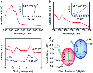
To determine the direct Z-scheme heterojunction, the bandgap (Eg) and valence band (VB) information of C3N4 and NC are gathered. As shown in Fig. 4a, there is an intrinsic absorption edge at around 420 nm for C3N4, and the related band gap is estimated to be 3.02 eV. NC exhibits a broad absorption in the UV-vis region, and the estimated bandgap is 2.34 eV (Fig. 4b). In Fig. 4c, the VBs of C3N4 and NC are confirmed to be 1.42 and 3.11 eV through the valence band X-ray photoelectron spectroscopy (VB-XPS). Then, CB positions of C3N4 and NC are determined to be −1.60 and 0.77 eV, based on the following equation: ECB = EVB − Eg, where ECB, EVB, and Eg are the conduction band position, valence band position, and bandgap, respectively.50 The CB positions of C3N4 and NC are consistent with the experimental results in Fig. S3a and b.† The resulting charge transfer mechanism of C3N4/NC is plotted in Fig. 4d. According to the staggered band structures of C3N4 and NC, the excited electrons in the CB of NC are paired with the holes in the VB of C3N4, while the remaining electrons stay in the CB (−1.60 eV). As the CB position of C3N4 at −1.60 eV is more negative than the water reduction potential (−0.41 eV), it is thermodynamically favorable for those accumulated electrons in the CB of C3N4 to trigger H2 evolution. Meanwhile, the holes remain in the VB of NC at 3.11 eV, which is beneficial to the efficient oxidation reaction. The specific oxidation reaction paths including intermediates are shown in Fig. S4.† Therefore, a direct Z-scheme heterojunction is achieved by pairing C3N4 with NC.
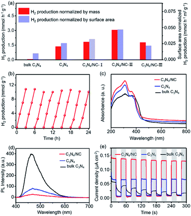
The visible-light photocatalytic performance of H2 production is evaluated by using an online photocatalytic test instrument (Fig. S5†). As presented in Fig. 5a, C3N4 shows a sharp improvement of visible light photocatalytic H2 evolution activity compared with bulk C3N4. The enhanced H2 production rate is partially attributed to the larger surface area (from 6.4 m2 g−1 to 52.5 m2 g−1, Fig. 3d and S2†) resulting from the formation of 2D porous sheets. Furthermore, the H2 evolution rate of C3N4 can be boosted by constructing 2D C3N4/NC with a direct Z-scheme heterojunction through regulating the mass ratio of NC in C3N4/NC. As expected, all three C3N4/NC samples show considerably improved H2 production rate and the optimized C3N4/NC-II exhibits the highest H2 evolution rate of 3.060 mmol h−1 g−1 (Fig. 5a and S6†) and external quantum efficiency (EQE, 6.79% at 400 nm). Such an impressive H2 production rate in C3N4/NC is over 46 fold that of bulk C3N4. On the one hand, the formation of a well-defined 2D–2D structure results in large interfacial contact for charge separation and surface area for photocatalysis. On the other hand, benefiting from the direct Z-scheme mechanism (Fig. 4d), charge carriers are spatially separated, and electrons with strong reducing capacity are preserved in the CB of C3N4, which highly retains the reduction ability of C3N4/NC to reduce H+ into H2. However, the excessive NC will cover the surface of C3N4 (Fig. S1†), resulting in a decrease in the effective active sites for H2 production. This is proved through the H2 evolution rate normalized by the surface area, as shown in Fig. 5a. Hence, C3N4/NC demonstrates superior photocatalytic activity of H2 production compared with other carbon nitride-based systems in previous reports (Tables S2 and S3†). The stability of the optimized g-C3N4/NC-II is evaluated by recycling it over eight cycles for 24 h (Fig. 5b). Remarkably, the H2 production remains consistent without deactivation and the XPS spectra slightly change (Fig. S7†) after the whole eight cycles, manifesting its excellent stability.
To reveal the fundamental mechanism behind the significantly enhanced photocatalytic performances of 2D direct Z-scheme C3N4/NC photocatalysts, the optical properties, transient photocurrent response, photoluminescence (PL), and electrochemical impedance spectra (EIS) are comprehensively studied. The UV-vis diffuse reflectance spectra (DRS) show that the ranking of the visible light absorption strength is C3N4/NC > C3N4 > bulk C3N4 (Fig. 5c). Furthermore, a higher charge separation rate can be reflected by the lower fluorescence emission intensity through the PL spectroscopy,51,52 where the PL intensity of C3N4/NC is lower than that of bulk C3N4 and C3N4 (Fig. 5d). The single peak of PL emission at 465 nm is ascribed to the bandgap transition of C3N4. More importantly, the separation/transfer capability of charge carriers is evaluated through the transient photocurrent response.53 As displayed in Fig. 5e, C3N4/NC exhibits a significantly higher photocurrent density than those of bulk C3N4 and C3N4. To reveal the interfacial charge carrier transfer resistance, EIS is carried out. In Fig. S8,† the EIS spectra of C3N4/NC and C3N4 are modeled through the equivalent Randle circuit composed of the interfacial charge transfer resistance at the electrode/electrolyte interface (Rct), electrolyte solution resistance (Rs), and constant phase element (CPE).54,55 A lower Rct of 455 Ω in C3N4/NC is achieved when compared to that of C3N4 (576 Ω). These characterization results consistently support that the enhanced photocatalytic H2 evolution activity is mainly ascribed to the improved separation and transfer of charge carriers, which originates from the synthetic merits of the direct Z-scheme heterojunction and the 2D–2D structure of the C3N4/NC photocatalysts.
In summary, we have synthesized 2D direct Z-scheme C3N4/NC photocatalysts by a gas template-assisted thermal condensation method. We demonstrated that the synthesized C3N4/NC has well-defined 2D–2D interfaces and a direct Z-scheme heterojunction via π–π stacking interaction. The direct Z-scheme heterojunction facilitates the charge–hole separation and the retention of redox ability, and large interfacial contact from 2D–2D interaction further promotes the photocatalysis of hydrogen evolution. The highest H2 evolution rate of C3N4/NC reaches 3.060 mmol h−1 g−1, which is 46 times higher than that of bulk C3N4. The enhanced photocatalytic performances are attributed to the improved separation and transfer of charge carriers benefiting from the direct Z-scheme heterojunction and the 2D–2D structure. This work enables the significant improvement of charge carrier separation by integrating 2D materials with direct Z-scheme heterojunctions, which provides a novel material design strategy for heterojunctions.
Conflicts of interest
There are no conflicts to declare.Acknowledgements
We acknowledge the funding support from the National Science Foundation of China (51902156 and Distinguished Young Scientist No. 51425301), the Youth Project of the Natural Science Foundation of Jiangsu Province, China (BK20171008 and BK20200713) and the Natural Science research in Colleges and universities of Jiangsu Province (20KJB150027).Notes and references
- T. Hisatomi and K. Domen, Nat. Catal., 2019, 2, 387–399 CrossRef CAS.
- K. Maeda, K. Teramura, D. Lu, T. Takata, N. Saito, Y. Inoue and K. Domen, Nature, 2006, 440, 295 CrossRef CAS PubMed.
- C. Liu, B. C. Colón, M. Ziesack, P. A. Silver and D. G. Nocera, Science, 2016, 352, 1210–1213 CrossRef CAS PubMed.
- K. Khan, X. Tao, Y. Zhao, B. Zeng, M. Shi, N. Ta, J. Li, X. Jin, R. Li and C. Li, J. Mater. Chem. A, 2019, 7, 15607–15614 RSC.
- J. Messinger, O. Ishitani and D. Wang, Sustainable Energy Fuels, 2018, 2, 1891–1892 RSC.
- J. Deng, Y. Su, D. Liu, P. Yang, B. Liu and C. Liu, Chem. Rev., 2019, 119, 9221–9259 CrossRef CAS PubMed.
- C. Liu, N. P. Dasgupta and P. Yang, Chem. Mater., 2014, 26, 415–422 CrossRef CAS.
- Y. Lin, G. Yuan, S. Sheehan, S. Zhou and D. Wang, Energy Environ. Sci., 2011, 4, 4862–4869 RSC.
- (a) P. Zhang, L. Gao, X. Song and J. Sun, Adv. Mater., 2015, 27, 562–568 CrossRef CAS PubMed; (b) D. Ren, W. Zhang, Y. Ding, R. Shen, Z. Jiang, X. Lu and X. Li, Sol. RRL, 2019, 4, 1900423 CrossRef; (c) R. Shen, D. Ren, Y. Ding, Y. Guan, Y. H. Ng, P. Zhang and X. Li, Sci. China Mater., 2020, 63, 2153–2188 CrossRef CAS; (d) R. Shen, J. Xie, Q. Xiang, X. Chen, J. Jiang and X. Li, Chin. J. Catal., 2019, 40, 240–288 CrossRef CAS.
- Y. Wang, A. Vogel, M. Sachs, R. S. Sprick, L. Wilbraham, S. J. A. Moniz, R. Godin, M. A. Zwijnenburg, J. R. Durrant, A. I. Cooper and J. Tang, Nat. Energy, 2019, 4, 746–760 CrossRef CAS.
- (a) S. Li, P. Zhang, X. Song and L. Gao, ACS Appl. Mater. Interfaces, 2015, 7, 18560–18565 CrossRef CAS PubMed; (b) Z. Liang, R. Shen, Y. H. Ng, P. Zhang, Q. Xiang and X. Li, J. Mater. Sci. Technol., 2020, 56, 89–121 CrossRef; (c) K. Khan, X. Tao, Y. Zhao, B. Zeng, M. Shi, N. Ta, J. Li, X. Jin, R. Li and C. Li, J. Mater. Chem. A, 2019, 7, 15607–15614 RSC; (d) Y. Li, Z. Jin, L. Zhang and K. Fan, Chin. J. Catal., 2019, 40, 390–402 CrossRef CAS; (e) Z. Li, Y. Ma, X. Hu, E. Liu and J. Fan, Chin. J. Catal., 2019, 40, 434–445 CrossRef CAS; (f) R. Shen, K. He, A. Zhang, N. Li, Y. H. Ng, P. Zhang, J. Hu and X. Li, Appl. Catal., B, 2021, 291, 120104 CrossRef CAS; (g) Y. Xi, X. Zhang, Y. Shen, W. Dong, Z. Fan, K. Wang, S. Zhong and S. Bai, Appl. Catal., B, 2021, 297, 120411 CrossRef CAS.
- Q. Xu, L. Zhang, J. Yu, S. Wageh, A. A. Al-Ghamdi and M. Jaroniec, Mater. Today, 2018, 21, 1042–1063 CrossRef CAS.
- (a) Y. Yin, C. Wu, G. Yu, H. Wang, Q. Han and L. Qu, J. Mater. Chem. A, 2021, 9, 7881–7887 RSC; (b) S. Wageh, A. A. Al-Ghamdi, R. Jafer, X. Li and Z. Peng, Chin. J. Catal., 2021, 42, 667–669 CrossRef CAS; (c) R. Shen, W. Liu, D. Ren, J. Xie and X. Li, Appl. Surf. Sci., 2019, 466, 393–400 CrossRef CAS; (d) Y. Ren, D. Zeng and W.-J. Ong, Chin. J. Catal., 2019, 40, 289–319 CrossRef CAS; (e) S. Zhong, Y. Xi, Q. Chen, J. Chen and S. Bai, Nanoscale, 2020, 12, 5764–5791 RSC; (f) Y. Xi, W. Chen, W. Dong, Z. Fan, K. Wang, Y. Shen, G. Tu, S. Zhong and S. Bai, ACS Appl. Mater. Interfaces, 2021, 13, 39491–39500 CrossRef CAS PubMed.
- S. S. Lam, V.-H. Nguyen, M. T. Nguyen Dinh, D. Q. Khieu, D. D. La, H. T. Nguyen, D. V. N. Vo, C. Xia, R. S. Varma, M. Shokouhimehr, C. C. Nguyen, Q. V. Le and W. Peng, J. Mater. Chem. A, 2020, 8, 10571–10603 RSC.
- J. Low, J. Yu, M. Jaroniec, S. Wageh and A. A. Al-Ghamdi, Adv. Mater., 2017, 29, 1601694 CrossRef PubMed.
- A. J. Bard, J. Photochem., 1979, 10, 59–75 CrossRef CAS.
- F. Guo, W. Shi, H. Wang, M. Han, W. Guan, H. Huang, Y. Liu and Z. Kang, J. Hazard. Mater., 2018, 349, 111–118 CrossRef CAS PubMed.
- H. Tada, T. Mitsui, T. Kiyonaga, T. Akita and K. Tanaka, Nat. Mater., 2006, 5, 782–786 CrossRef CAS PubMed.
- W. Zhang, A. R. Mohamed and W.-J. Ong, Angew. Chem., Int. Ed., 2020, 59, 22894–22915 CrossRef CAS PubMed.
- G. S. Engel, T. R. Calhoun, E. L. Read, T.-K. Ahn, T. Mančal, Y.-C. Cheng, R. E. Blankenship and G. R. Fleming, Nature, 2007, 446, 782–786 CrossRef CAS PubMed.
- Z. Zhang, J. Huang, Y. Fang, M. Zhang, K. Liu and B. Dong, Adv. Mater., 2017, 29, 1606688 CrossRef PubMed.
- C. Zhao, Z. Chen, R. Shi, X. Yang and T. Zhang, Adv. Mater., 2020, 32, 1907296 CrossRef CAS PubMed.
- X. Wang, K. Maeda, A. Thomas, K. Takanabe, G. Xin, J. M. Carlsson, K. Domen and M. Antonietti, Nat. Mater., 2009, 8, 76–80 CrossRef CAS PubMed.
- B. P. Mishra and K. Parida, J. Mater. Chem. A, 2021, 9, 10039–10080 RSC.
- J. Liu, Y. Liu, N. Liu, Y. Han, X. Zhang, H. Huang, Y. Lifshitz, S.-T. Lee, J. Zhong and Z. Kang, Science, 2015, 347, 970–974 CrossRef CAS PubMed.
- W. Jiang, Y. Zhao, X. Zong, H. Nie, L. Niu, L. An, D. Qu, X. Wang, Z. Kang and Z. Sun, Angew. Chem., Int. Ed., 2021, 133, 6189–6194 CrossRef.
- D. Qu, J. Liu, X. Miao, M. Han, H. Zhang, Z. Cui, S. Sun, Z. Kang, H. Fan and Z. Sun, Appl. Catal., B, 2018, 227, 418–424 CrossRef CAS.
- L. Ai, R. Shi, J. Yang, K. Zhang, T. Zhang and S. Lu, Small, 2021, 2007523, DOI:10.1002/smll.202007523.
- J. Yu, T. Zhang and N. Wu, Sol. RRL, 2021, 5, 2100037 CrossRef.
- Z. R. Ismagilov, A. E. Shalagina, O. Y. Podyacheva, A. V. Ischenko, L. S. Kibis, A. I. Boronin, Y. A. Chesalov, D. I. Kochubey, A. I. Romanenko, O. B. Anikeeva, T. I. Buryakov and E. N. Tkachev, Carbon, 2009, 47, 1922–1929 CrossRef CAS.
- T. Ouyang, Y.-Q. Ye, C.-Y. Wu, K. Xiao and Z.-Q. Liu, Angew. Chem., Int. Ed., 2019, 58, 4923–4928 CrossRef CAS PubMed.
- X. Hou, L. Cui, H. Du, L. Gu, Z. Li and Y. Yuan, Appl. Catal., B, 2020, 278, 119253 CrossRef CAS.
- S. Yang, W. Li, C. Ye, G. Wang, H. Tian, C. Zhu, P. He, G. Ding, X. Xie, Y. Liu, Y. Lifshitz, S.-T. Lee, Z. Kang and M. Jiang, Adv. Mater., 2017, 29, 1605625 CrossRef PubMed.
- Q. Liu, H. Tian, Z. Dai, H. Sun, J. Liu, Z. Ao, S. Wang, C. Han and S. Liu, Nano-Micro Lett., 2020, 12, 1–15 CrossRef PubMed.
- C. Liu, Y. Zhang, F. Dong, A. H. Reshak, L. Ye, N. Pinna, C. Zeng, T. Zhang and H. Huang, Appl. Catal., B, 2017, 203, 465–474 CrossRef CAS.
- N. C. T. Martins, J. Ângelo, A. V. Girão, T. Trindade, L. Andrade and A. Mendes, Appl. Catal., B, 2016, 193, 67–74 CrossRef CAS.
- L. Lei, W. Wang, C. Wang, H. Fan, A. K. Yadav, N. Hu, Q. Zhong and P. Müller-Buschbaum, J. Mater. Chem. A, 2020, 8, 23812–23819 RSC.
- X. Chen, R. Shi, Q. Chen, Z. Zhang, W. Jiang, Y. Zhu and T. Zhang, Nano Energy, 2019, 59, 644–650 CrossRef CAS.
- Q. Liang, Z. Li, X. Yu, Z. Huang, F. Kang and Q. Yang, Adv. Mater., 2015, 27, 4634–4639 CrossRef CAS PubMed.
- P. Xia, B. Zhu, J. Yu, S. Cao and M. Jaroniec, J. Mater. Chem., 2017, 5, 3230–3238 RSC.
- (a) F. Wang, Y. Wu, Y. Wang, J. Li, X. Jin, Q. Zhang, R. Li, S. Yan, H. Liu and Y. Feng, Chem. Eng. J., 2019, 356, 857–868 CrossRef CAS; (b) J. Pan, S. Shen, W. Zhou, J. Tang, H. Ding, J. Wang, L. Chen, C.-T. Au and S.-F. Yin, Acta Phys.-Chim. Sin., 2020, 36, 1905068 Search PubMed; (c) Y. Chen, L. Li, Q. Xu, T. Düren, J. Fan and D. Ma, Acta Phys.-Chim. Sin., 2020, 2009080 Search PubMed; (d) J. Huang, J. Du, H. Du, G. Xu and Y. Yuan, Acta Phys.-Chim. Sin., 2020, 36, 1905056 Search PubMed.
- C. Liu, H. Huang, W. Cui, F. Dong and Y. Zhang, Appl. Catal., B, 2018, 230, 115–124 CrossRef CAS.
- W. Li, Q. Ma, X. Wang, X.-s. Chu, F. Wang, X.-c. Wang and C.-y. Wang, J. Mater. Chem. A, 2020, 8, 19533–19543 RSC.
- Y. Wang, Q. Xia, X. Bai, Z. Ge, Q. Yang, C. Yin, S. Kang, M. Dong and X. Li, Appl. Catal., B, 2018, 239, 196–203 CrossRef CAS.
- Q. Tay, P. Kanhere, C. F. Ng, S. Chen, S. Chakraborty, A. C. H. Huan, T. C. Sum, R. Ahuja and Z. Chen, Chem. Mater., 2015, 27, 4930–4933 CrossRef CAS.
- M. Shi, T. Wu, X. Song, J. Liu, L. Zhao, P. Zhang and L. Gao, J. Mater. Chem. A, 2016, 4, 10666–10672 RSC.
- H. Yu, L. Shang, T. Bian, R. Shi, G. I. Waterhouse, Y. Zhao, C. Zhou, L. Z. Wu, C. H. Tung and T. Zhang, Adv. Mater., 2016, 28, 5080–5086 CrossRef CAS PubMed.
- H. Zhang, L. Zhao, F. Geng, L.-H. Guo, B. Wan and Y. Yang, Appl. Catal., B, 2016, 180, 656–662 CrossRef.
- H. Liu, J. Liang, S. Fu, L. Li, J. Cui, P. Gao, F. Zhao and J. Zhou, Colloids Surf., A, 2020, 591, 124552 CrossRef CAS.
- Y. Xu and M. A. A. Schoonen, Am. Mineral., 2000, 85, 543–556 CrossRef CAS.
- W. Jiang, X. Zong, L. An, S. Hua, X. Miao, S. Luan, Y. Wen, F. F. Tao and Z. Sun, ACS Catal., 2018, 8, 2209–2217 CrossRef CAS.
- Y. Li, Z. Liu, X. Lu, Z. Su, Y. Wang, R. Liu, D. Wang, J. Jian, J. H. Lee, H. Wang, Q. Yu and J. Bao, Nanoscale, 2015, 7, 1601–1605 RSC.
- J. E. Thorne, Y. Zhao, D. He, S. Fan, S. Vanka, Z. Mi and D. Wang, Phys. Chem. Chem. Phys., 2017, 19, 29653–29659 RSC.
- J. Wang, Q. Zhou, Y. Shen, X. Chen, S. Liu and Y. Zhang, Langmuir, 2019, 35, 12366–12373 CrossRef CAS PubMed.
- J. Wang, Y. Sun, L. Fu, Z. Sun, M. Ou, S. Zhao, Y. Chen, F. Yu and Y. Wu, Nanoscale, 2020, 12, 22030–22035 RSC.
Footnotes |
| † Electronic supplementary information (ESI) available: Experimental details and supplementary figures and tables. See DOI: 10.1039/d1na00629k |
| ‡ These authors contributed equally. |
| This journal is © The Royal Society of Chemistry 2021 |

