
 Open Access Article
 This Open Access Article is licensed under a Creative Commons Attribution-Non Commercial 3.0 Unported Licence
Meso- and macroporous silica-based arsenic adsorbents: effect of pore size, nature of the active phase, and silicon release†
Marco
Sanna Angotzi‡
 ab,
Valentina
Mameli‡
ab,
Claudio
Cara
ab,
Konstantin B. L.
Borchert
c,
Christine
Steinbach
c,
Regine
Boldt
c,
Dana
Schwarz
*c and
Carla
Cannas
*ab
ab,
Valentina
Mameli‡
ab,
Claudio
Cara
ab,
Konstantin B. L.
Borchert
c,
Christine
Steinbach
c,
Regine
Boldt
c,
Dana
Schwarz
*c and
Carla
Cannas
*ab
aDepartment of Chemical and Geological Sciences, University of Cagliari, S.S. 554 bivio per Sestu, 09042 Monserrato, CA, Italy. E-mail: ccannas@unica.it
bConsorzio Interuniversitario Nazionale per la Scienza e Tecnologia dei Materiali (INSTM), Cagliari Unit, Via Giuseppe Giusti 9, 50121 Firenze (FI), Italy
cLeibniz-Institut für Polymerforschung Dresden e.V., Hohe Str. 6, 01069 Dresden, Germany. E-mail: schwarz-dana@ipfdd.de
First published on 27th August 2021
Abstract
Arsenic pollution in ground and drinking water is a major problem worldwide due to the natural abundance of arsenic by dissolution from ground sediment or mining activities from anthropogenic activities. To overcome this issue, iron oxides as low-cost and non-toxic materials, have been widely studied as efficient adsorbents for arsenic removal, including when dispersed within porous silica supports. In this study, two head-to-head comparisons were developed to highlight the As(V)-adsorptive ability of meso- and macrostructured silica-based adsorbents. First, the role of the textural properties of a meso-(SBA15) and macrostructured (MOSF) silica support in affecting the structural-morphological features and the adsorption capacity of the active phase (Fe2O3) have been studied. Secondly, a comparison of the arsenic removal ability of inorganic (Fe2O3) and organic (amino groups) active phases was carried out on SBA15. Finally, since silica supports are commonly proposed for both environmental and biomedical applications as active phase carriers, we have investigated secondary silicon and iron pollution. The batch tests at different pH revealed better performance from both Fe2O3-composites at pH 3. The values of qm of 7.9 mg g−1 (53 mg gact−1) and 5.5 mg g−1 (37 mg gact−1) were obtained for SBA15 and MOSF, respectively (gact stands for mass of the active phase). The results suggest that mesostructured materials are more suitable for dispersing active phases as adsorbents for water treatment, due to the obtainment of very small Fe2O3 NPs (about 5 nm). Besides studying the influence of the pore size of SBA15 and MOSF on the adsorption process, the impact of the functionalization was analyzed on SBA15 as the most promising sample for As(V)-removal. The amino-functionalized SBA15 adsorbent (3-aminopropyltriethoxysilane, APTES) exhibited a qm of 12.4 mg g−1 and faster kinetics. Furthermore, issues associated with the release of iron and silicon during the sorption process, causing secondary pollution, were evaluated and critically discussed.
Introduction
As observed in more than 70 countries, arsenic pollution is one of the most critical environmental issues, due to its high toxicity in low concentrations and the worldwide contamination of soils and water.1,2 The presence of a high quantity of arsenic may be due to natural processes (dissolution of minerals, microbial activity, etc.) or human activities, such as mining, metallurgical industry, combustion of fossil fuels, and pesticides.3 The World Health Organization has set a threshold level of 10 μg L−1 for arsenic content in drinking water. However, there are several parts of the world where people only have access to contaminated water. In the natural aquatic environment (4 ≤ pH ≤ 10), inorganic arsenic exists in pentavalent (As(V)) and trivalent (As(III)) forms, generating deprotonated arsenic (H2AsO4−, HAsO42−) and arsenious acid (H3AsO3).4 There are various factors that can influence the speciation, mobility, bioavailability, and solubility of arsenic in water, as the pH, redox potential, competing ions, and biological transformation, thus determining the different toxicity levels.5–8 For these reasons, global policies consider arsenic remediation urgent, and there are several removal methods including: precipitation, filtration, electrocoagulation, membrane processes, and adsorption.9–12 Among them, adsorption is becoming a more and more studied and applied technology, thanks to the high efficiency, low cost, regeneration possibility, and flexibility.12–15 There are indeed many materials employed for the adsorption of arsenic, such as activated carbon,16–18 zeolites,19–21 MOFs,5,9,22,23 graphene oxides,5,24 carbon nanotubes,5,24,25 and nanoparticles (NPs).3,24,26–28 The latter ones, because of their small size, possess a high surface/volume ratio, and therefore high accessibility of active sites, and are intriguing for this type of application. For instance, iron oxides are known to be active for the removal of arsenic,29–32 both in the form of As(III) and As(V), and are also low cost, easy to synthesise, and non-toxic.33–35 However, chemical stability at low pH, the accessibility of active sites upon aggregation, and the regeneration of NPs should be considered. In this framework, iron oxide NPs can be grown within silica pores (meso or macro), having high specific surface area to achieve high accessibility to the active phase, being stable at acidic pH, and preventing the leaking and the aggregation of the attached NPs.36–39 Moreover, silica can be easily functionalized with organic molecules and biopolymers, able to link metals and oxyanions.40–49 Porous amorphous silica can feature micro-, meso-, or macropores, in an ordered or disordered structure. Usually, ordered mesoporous silicas, i.e., mesostructured, such as MCM-41, MCM-48, SBA-15, and KIT-6, are the most employed supports for hosting active phases, and they have already been successfully adopted for arsenic removal in composites with TiO2,50 CoFe2O4,36 MnO2,37 CuO,38 and Fe2O3.39 Mesostructured silica has also been applied for water remediation with several organic functional groups, especially thiol40–43 and amino functionalities,44–49 revealing high performance and easy regeneration. In addition, macroporous silica (macroporous ordered siliceous foams, MOSF)51–61 has been used as a support, sometimes coupled with mesopores.62,63 The wider pores, even though the matrix features less surface area, could, in principle, facilitate the accessibility of the sites, allowing an increase in operating flux and pressure of the ingoing water as a potential column material. Indeed, despite mesopores allowing the access and transfer of molecules and ions, such as arsenate, the organic grafting as well as the functionalization with inorganic phases could yield in pore blockage and uneven distribution within the pores, affecting the kinetics.64–66 Both these types of support offer the possibility to host various inorganic and organic active phases toward different pollutants, paving the way to a single multitarget adsorbent platform. Nevertheless, the role of the different textural properties of a meso- or macrostructured silica support in leading to different structure, morphology, and adsorption capacity for the same active phase has not been investigated so far, together with the comparison of arsenic removal capacity of inorganic and organic arsenic active phases. Another lacking aspect that is rarely treated is the risk of secondary pollution deriving from the use of sorbents. This is probably due to the fact that among the water treatment techniques, the most promising one in terms of a minimal production of secondary pollutants is based on the use of sorbents, made up of different materials.12,67 However, it is known in the literature that silica, when nanosized, can show size-dependent cytotoxicity.68,69 Moreover, the toxicity of iron oxide magnetic nanoparticles is not well explored despite their extensive use in biomedicine and environmental applications.70For this reason, it is important to provide evidence for silica supports and iron oxide active nanophase as being mechanically and chemically stable under adsorption test conditions. These skipped issues are key ones, and might even prevent the use of the systems, or at least should be taken into account for further proper development of subsequent adsorbent technologies.
In this work, a head-to-head comparison between meso- and macroporous ordered silica-based arsenic adsorbents, as well as between inorganic and organic active phases loaded on the same support, has been presented. In detail, the arsenic removal from 15% w/w iron oxide-based mesostructured (15Fe-SBA15) and macrostructured (15Fe-MOSF) silica composites has been compared, studying the pH and initial concentration influence in batch tests. The iron oxide-SBA-15 composite has been further compared with an amino-functionalized SBA-15 (APTES-SBA15). Finally, attention has also been paid to the possible contamination of water by silicon and iron released from the composites during the adsorption tests.
Experimental
Chemicals
Pluronic 123 (P123), hydrochloric acid (37% w/w), sodium acetate (NaAc, 99% w/w), sodium sulfate (99.2% w/w), and toluene (99.7% w/w) were purchased from VWR International S.r.l. Acetic acid (HAc, 99.8% w/w) and tetraethyl orthosilicate (TEOS, 98% w/w) were purchased from Aldrich. 3-Aminopropyltriethoxysilane (APTES, 97%), ethanol (96% w/w), iron(III) nitrate nonahydrate (98% w/w), and n-hexane (97% w/w) were purchased from Sigma-Aldrich. For the pH adjustment of the adsorption experiments, NaOH and HCl (Titrisol®, 0.1 M and 1 M) were purchased from Merck. For the adsorption experiments, arsenic(V) standard solution (10![[thin space (1/6-em)]](https://www.rsc.org/images/entities/char_2009.gif) 000 μg mL−1 As in 10% HNO3) (item number 4400-10M31) was used from CPI International. For all adsorption experiments, ultrapure water purified by a Milli-Q Advantage A10® system (total organic carbon = 5 ppb, specific resistance of 0.741 μS cm−1) was used.
000 μg mL−1 As in 10% HNO3) (item number 4400-10M31) was used from CPI International. For all adsorption experiments, ultrapure water purified by a Milli-Q Advantage A10® system (total organic carbon = 5 ppb, specific resistance of 0.741 μS cm−1) was used.
Synthesis of the silica supports
Synthesis of the adsorbents
Sorption tests
0.1 g of adsorbent was placed in a 50 mL centrifuge tube with 20 mL of arsenic solution at different pH (3–9), obtained by adding NaOH or HCl. Different concentrations of arsenic were tested, from 1 to 200 mg L−1. The tubes were placed in a roller shaker for 10 hours and 9 more hours at rest. Afterwards, the tubes were centrifuged at 10000 rpm for 10 minutes in order to separate the solid from the liquid, then the liquid was filtered through a 0.45 μm sieve. 8 mL of solution were transferred to a 15 mL test tube together with 2 mL of nitric acid 20% w/w, and analyzed by ICP-OES.
The adsorbed amount of arsenic (qe) was calculated by eqn (1):
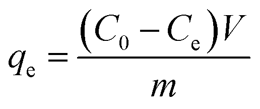 | (1) |
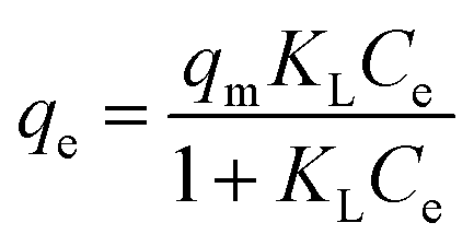
In the Langmuir isotherm model (eqn (2)), qm is the maximum adsorption capacity (mg g−1), and KL is the Langmuir constant (L mg−1), which is related to the energy of adsorption. It assumes that each active site is equivalent, and it is energetically irrelevant whether adjacent sorption centers are empty or occupied.
 | (2) |
In the Freundlich isotherm model (eqn (3)), KF is the Freundlich constant, which gives an estimation of the amount of sorbate retained per gram of adsorbent at the equilibrium concentration (mg1−1/n L1/n g−1), and n is a measure of the nature and strength of the sorption process and the distribution of active sites related to the surface heterogeneity (the heterogeneity of the system increases with n). It therefore assumes that the sorption process occurs on non-equivalent active sites, which is due to repulsion between sorbent species.
| qe = KFCe1/n | (3) |
In the Temkin isotherm model (eqn (4)), bT (J g mol−1 L−1) and KT (mg L−1) are parameters describing the adsorbate–adsorbent interactions.
 | (4) |
It assumes that the heat of adsorption decreases linearly with increasing amount of adsorbed species.
The Redlich–Peterson isotherm model (eqn (5)) is a hybrid between the Langmuir and Freundlich models.
 | (5) |
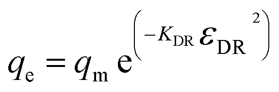
In the Dubinin–Radushkevich isotherm model (eqn (6)), εDR (kJ mol−1) and KDR (mg L−1) are the Dubinin–Radushkevich isotherm variable and constant, respectively.
 | (6) |
The model is used to differentiate between physisorption and chemisorption. The mean free energy of adsorption Eads (kJ mol−1) can be calculated by the following eqn (7).
 | (7) |
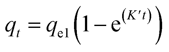
For the kinetics, the adsorbed amount of arsenic at a certain time (qt) was calculated through eqn 8
 | (8) |
The plotted data qtvs. Ct was then fitted by the pseudo-first order (eqn (9))79 and pseudo-second order (eqn (10)) kinetic models.80
 | (9) |
 | (10) |
| ln(qe − qt) = lnqe − K′t | (11) |
 | (12) |
The kinetic data were also fit by the intraparticle diffusion model (eqn (13))80
 | (13) |
Characterization
The solutions were analyzed by inductively coupled plasma-optical emission spectrometry (ICP-OES) using an iCAP 7400 device from Thermo Scientific. Thus, 9 standards were used: standard 1: As (200 mg L−1); standard 2: As (100 mg L−1), Si (100 mg L−1), Fe (100 mg L−1); standard 3: As (50 mg L−1), Si (50 mg L−1), Fe (50 mg L−1); standard 4: As (10 mg L−1), Si (10 mg L−1), Fe (10 mg L−1); standard 5: As (5 mg L−1), Si (5 mg L−1), Fe (5 mg L−1); standard 6: As (1 mg L−1), Si (1 mg L−1), Fe (1 mg L−1); standard 7: As (0.5 mg L−1); standard 8: As (0.1 mg L−1); standard 9: As (0.05 mg L−1). To each sample (4 mL) 4 mL of water and 1 mL of a 20% w/w nitric acid was added prior to analysis.The sorbent samples were characterized by small-angle and wide-angle X-ray diffraction (SA-XRD, WA-XRD, respectively) using a Seifert X3000 Cu Kα radiation (1.5418 Å). Calibration of peak position and instrumental width were done using powder LaB6 from NIST. Refinement of the structural parameters81 was performed by the Rietveld method using MAUD software,82 adopting the recommended fitting procedures.83 CIF structure COD ID used for the refinement is 1010369.84 Wall thickness was calculated as the difference between the lattice parameter (a0) obtained by SA-XRD and the pore diameter (Dpore) by N2 physisorption.
Transmission electron microscopy (TEM) micrographs and STEM-EDX analyses were obtained using a JEOL JEM 1400 Plus system operating at 120 kV, equipped with an Oxford Aztec spectrometer. The specimens were prepared by dropping an ethanol dispersion of the sample on a 200-mesh carbon-coated copper grid.
Thermogravimetric analysis (TGA) curves were obtained using a PerkinElmer STA 6000, in the range 25–850 °C, with a heating rate of 10 °C min−1 under 40 mL min−1 O2 flow.
Gas sorption measurements were performed using the Autosorb iQ MP from Quantachrome Instruments. The samples were activated by degassing in a vacuum (5 × 10⁻¹⁰ mbar) at 250 °C for 12 hours (heating rate 10 °C min−1). The nitrogen sorption measurements were performed at 77 K. The Brunauer–Emmett–Teller (BET) specific surface area was calculated from the adsorption data in the p/p0 range 0.05–0.17.31 Total pore volume was calculated at p/p0 = 0.875, while mean pore diameter was determined by applying both the density functional theory (DFT) model (assuming N2 as the adsorptive gas, cylindrical pores, and a silica-based surface) on the isotherm adsorption branch, and the Barrett–Joyner–Halenda (BJH) model76 to the isotherm desorption branch.
Particle size measurements were measured at Morphologi from Malvern. An 8 mm3 sample was applied to a glass plate with the sample dispersion unit (SDU) with low energy. The measurements were performed with the 10× lens (3.5 μm–210 μm) and 50× lens (0.5 μm–40 μm) with differential Z stacking.
SEM-EDX analysis was carried out using a scanning electron microscope (SEM Ultra Plus, Carl Zeiss Microscopy GmbH, Germany), equipped with an energy-dispersive X-ray spectroscopy detector (EDX XFlash Quad 5060F, Bruker Nano GmbH, Germany). For this purpose, the samples were fixed with double-sided adhesive carbon tape on an aluminum pin sample tray and covered with platinum for SEM, and with carbon for EDX, before the investigation starts. The EDX measurements were carried out with an acceleration voltage of 6 keV at different magnifications. For topography and material contrast SEM imaging, an acceleration voltage of 3 keV was used.
Zeta potential measurements were performed through a Malvern Instrument Zetasizer Nano ZSP equipped with a He–Ne laser (λ = 633 nm, max. 5 mW) and operated at a scattering angle of 173°, using Zetasizer software (version 7.03) to analyze the data. The sample was prepared by suspending the composites (5 mg mL−1) in distilled water and adding HCl and NaOH to modify the pH from 2 to 9. The scattering cell temperature was fixed at 25 °C.
Results and discussion
Characterization of SBA15 and MOSF supports
The mesostructured (SBA15) and macrostructured (MOSF) silica supporting materials were synthesized and their porosity and morphology subsequently studied by SA-XRD, N2-physisorption, TEM, and SEM. The SA-XRD patterns of the bare SBA15 sample (Fig. 1a) revealed the presence of three clear signals ascribable to the hexagonal structure of the mesopores (space group P6mm). In the case of MOSF, no signals were revealed at small angles, as expected for macrostructured materials.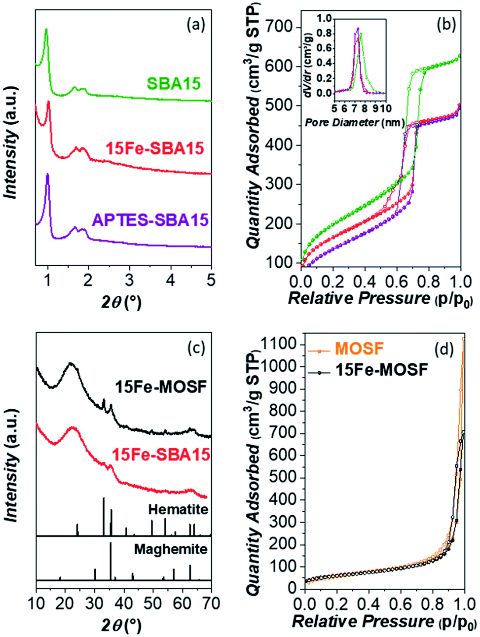 | ||
| Fig. 1 Small-angle XRD patterns (a), N2-physisorption isotherms (adsorption in full circles and desorption in empty circles) (b) and DFT-calculated pore size distributions (inset) of the bare SBA-15, 15Fe-SBA15, and APTES-SBA15. Wide-angle XRD pattern (c), and N2-physisorption isotherms (d), of the bare MOSF and 15Fe-MOSF. | ||
| Sample | S BET (m2 g−1) | PV (cm3 g−1) | D p (DFT) (nm) | D p (BJH) (nm) | w t (DFT) (nm) | w t (BJH) (nm) | d 100 (nm) | a 0 (nm) |
|---|---|---|---|---|---|---|---|---|
| SBA15 | 721 | 0.94 | 7.6 | 6.3 | 2.9 | 4.2 | 9.1 | 10.5 |
| 15Fe-SBA15 | 600 | 0.73 | 7.2 | 4.5, 5.8 | 2.8 | 4.2 | 8.6 | 10.0 |
| APTES-SBA15 | 502 | 0.72 | 7.2 | 5.8 | 3.1 | 4.5 | 8.9 | 10.3 |
| MOSF | 229 | 0.26 | n.a. | n.a. | n.a. | n.a. | n.a. | n.a. |
| 15Fe-MOSF | 219 | 0.24 | n.a. | n.a. | n.a. | n.a. | n.a. | n.a. |
The N2-physisorption isotherms reported in Fig. 1b show the presence of an IVa isotherm for the SBA15 sample, which is typical for mesoporous materials. The mesoporous contribution of SBA15 is confirmed by the distinct step in the range 0.6–0.8 p/p0 related to the capillary condensation phenomenon.85 The calculated surface area for the bare support was 721 m2 g−1, while the pore size, calculated by the DFT and BJH models, resulted in 7.6 nm and 6.3 nm (Table 1, Fig. S1 and S3†). From the difference between a0 and Dp, it is possible to estimate the thickness of the pore walls, which is about 3 nm from the DFT data and about 4 nm from the BJH model (Table 1). On the contrary, the bare MOSF sample featured a type II isotherm (Fig. 1d), typical of macroporous materials, with a specific surface area of 229 m2 g−1, and with no micro or mesoporous contributions (Table 1, Fig. S2†).
The secondary electron (SE)-SEM images of the two supports, shown in Fig. 2, S4a and c,† highlight their morphological features. Prisms with a hexagonal basis of about 500–700 nm and height of about 700–1000 nm are present in the case of SBA15 (Fig. 2a, b and S4a†). Hollow spheroidal and hemispheroidal particles with sizes in the 150–1000 nm range are visible for MOSF, although some larger particles are also present (Fig. 2e, f and S4c†). The particle size distribution obtained by image analysis (Fig. S5†), indicates the formation of agglomerates of the primary submicrometric particles with a maximum in the size distribution of about 30 μm for the SBA15, and about 150 μm for the MOSF sample, with a number-based circularity factor of around 0.5 for both samples (Table S1†). Both MOSF and SBA15 samples showed an even grey color distribution in the backscattered (BSE) SEM images (Fig. 2c and g). The hexagonal mesostructure of SBA15 cannot be seen due to the reduced pore size. On the contrary, a honeycomb architecture of the macropores of about 70–120 nm is clearly visible for the MOSF support.
 | ||
| Fig. 2 SEM images of SBA15 (secondary electron (SE): (a and b); backscattered electron (BSE): (c)), and MOSF (SE: (e and f); BSE: (g)) supports. TEM images of SBA15 (d) and MOSF (h) supports. | ||
The TEM images of the bare SBA15 sample display at low magnification (Fig. S6†), particles of about 1 μm, in agreement with SEM data. At higher magnification (Fig. 2d), we see the sample features a well-ordered hexagonal porous structure with pores of 7–8 nm, consistent with the value found by N2-physisorption. Conversely, the presence of macropores of about 70–120 nm is clearly visible for the MOSF sample (Fig. 2h), in agreement with SEM analysis.
Characterization of iron oxide-based composites
The impregnation of the supports led to the obtainment of Fe2O3 NPs in the two most common crystalline phases, hematite and maghemite. Indeed, the WA-XRD patterns of the iron-bearing composites reported in Fig. 1c show a typical broad band of amorphous silica at about 22°, accompanied by reflections at higher angles related to the Fe2O3. For 15Fe-SBA15, the reflection at about 33° indicates the presence of hematite, whilst those at 35° and 62° are common reflections of maghemite and hematite. Aware of the limits in the Rietveld refinement on complex systems as amorphous nanocrystalline composites, an attempt was carried out taking into account the two phases (Fig. S7†). The analysis pointed out that maghemite is the primary phase (60–70%), and both phases are in the form of nanocrystals of about 4–6 nm in size. The results suggest that the particles are dispersed insides the pores, since the crystallites size (4–6 nm) is lower than the pore size (6–7 nm). This is also confirmed by the absence of nanoparticles outside the matrix, as evidenced by TEM. The presence of maghemite is also confirmed by its typical inter-lattice fringes revealed in the HRTEM image reported in Fig. S8.†72,73,86–88The three reflections at about 33°, 35°, and 62° in the 15Fe-MOSF WA-XRD pattern correspond again to the presence of both Fe2O3 polymorphs with 3–5 nm-sized maghemite as the primary component (70–80%), as confirmed by the tentative Rietveld analysis (Fig. S7†). In comparison to 15Fe-SBA15, a larger size (18–20 nm) of the hematite NPs derives from the potential to grow within the macropores without the typical constrictions of SBA15 mesochannels.
In order to further verify the Fe2O3 crystalline phase, DC magnetometry measurements were performed on both composites (DC Magnetic Measurements in ESI, Fig. S9 and Table S2†). The results suggest for both samples, the presence of maghemite NPs, which is in agreement with previous work.72,73,86,87 The maghemite NPs were found to be responsible for the observed magnetic behavior, confirming the hypothesis based on the Rietveld refinement of the WA-XRD patterns. On the contrary, DC magnetometry cannot confirm the presence of hematite NPs, whose magnetic behavior is probably masked by the most intense ferrimagnetic response.
The 15Fe-SBA15 SA-XRD pattern (Fig. 1a) features, as the parent support, the three typical reflections ascribable to the hexagonal pore structure, indicating the retention of the mesoporous structure after the impregnation process. The N2-physisorption isotherm (Fig. 1b) reveals a decrease in the surface area (from 717 m2 g−1 to 600 m2 g−1) and in the pore size (from 7.6 nm to 7.2 nm by DFT, from 6.3 nm to 5.8 nm and 4.5 nm by BJH, Fig. S1 and S3†), due to the presence of the active phase inside the pores in the form of small NPs, while pore walls were not affected (Table 1). The presence of a bimodal pore size distribution obtained by the BJH model for the 15Fe-SBA15 can be justified due to the presence of small NPs instead of the homogeneous film of the impregnating phase on the support, leading to smaller Fe2O3-impregnated pores and empty larger ones.89 Conversely, only a slight decrease in the surface area is evinced for the 15Fe-MOSF composite, from 226 m2 g−1 to 219 m2 g−1 (Fig. 1d and Table 1).
The morphological properties of the particles obtained by SE-SEM (Fig. S4†) and image analyses (Fig. S5 and Table S1†) indicate no remarkable changes in the composites with respect to the corresponding bare supports.
The backscattered (BSE) SEM images for the samples SBA15 and MOSF after the deposition of Fe2O3 are shown in Fig. 3a and d. The 15Fe-SBA15 image features different grey levels with darker and brighter rows ascribable to empty and full (Fe2O3-impregnated) cylindrical mesopores of silica, in agreement with the bimodal pore size distribution observed by the BJH model. The EDX spectrum of 15Fe-SBA15 (Fig. S10†) shows the presence of Fe and Si, while the Fe mapping images reveal a homogeneous distribution of Fe on the SiO2 surface (Fig. 3b). The honeycomb architecture of the macropores of the MOSF material is no longer visible after the impregnation procedure, probably due to the presence of the Fe2O3 NPs inside the pores (Fig. 3d). The contrast in the BSE-SEM images of 15Fe-MOSF shows even levels of grey, indicating homogeneous distribution of the small Fe2O3 NPs on the surface, as confirmed by the elemental mapping images and spectra (Fig. 3e and S10†). The TEM images of the two composites are shown in Fig. 3c and f. 15Fe-SBA15 reveals the presence of small particles (dark spots) or dark channels all over the support, compatible with the pore size of SBA15 and with no evidence of particles outside the support, due to the efficient impregnation strategy.72,73,86–90 On the contrary, the macroporous composite 15Fe-MOSF reveals the presence of iron oxide particles inside and outside the pores of about 10–20 nm. The particles are difficult to visualize due to the presence of the macroporous silica support. Nevertheless, it seems that the presence of the iron oxide particles induces an increase of the thickness of the macropore walls or the growth as a separated phase in contact with the matrix. From the EDX spectra of the outer particles surface, the local iron oxide loading can be determined (Table S3†). For 15Fe-SBA15, the outer surface weight loading for Fe2O3 is 10.9% w/w, while for 15Fe-MOSF, it is 24.2% w/w. These results indicate a higher incorporation of the Fe2O3 NPs into the pore structure for 15Fe-SBA15, while in the case of 15Fe-MOSF, the NPs are deposited more on the outer surface. Indeed, the total active phase content in the final sorbent is 15% w/w, as assured by the synthesis method that does not allow mass loss of the Fe2O3 phase.
 | ||
| Fig. 3 Backscattered electron (BSE) SEM images (a and d), EDX elemental Fe mapping ((b and e), Fe is shown in red), TEM images (c and f) of 15Fe-SBA15 and 15Fe-MOSF samples. | ||
To sum up, the porous matrix plays a crucial role in the formation of the active phase. While for SBA15 the mesopores induced the crystallization of maghemite and hematite nanocrystallites of particle diameters between 4 nm and 6 nm, in the case of MOSF the presence of macropores led to about 18–20 nm-sized hematite nanocrystallites and 3–5 nm-sized maghemite ones. Despite these differences, maghemite is the primary component (60–80%) in the form of very small NPs (3–6 nm), and both Fe2O3 phases are active towards arsenic species adsorption.29–32 Therefore, they were tested and compared in batch experiments at different pH values with the initial arsenic concentration.
Arsenic removal batch experiments
To estimate the optimal pH value for the maximum adsorption and analyze the adsorption mechanism, the first experiment focused on the pH-dependence of the adsorption capacity of the Fe2O3-based adsorbents. There are four As(V) species at different pH values having different charges, as can be seen in the Bjerrum plot in Fig. S11.†Different pH conditions were tested, namely pH 3, 4, 5, 7, and 9, to identify the best pH for the adsorption investigations in the studied experimental conditions. The results (Fig. 4, Table S4 and Fig. S11†) revealed a higher adsorption capacity at pH 3, which decreases with increasing pH, as already observed by other authors for both bare maghemite91 and hematite/maghemite composites.29,31,51 Better performances were achieved by the mesostructured composite, especially at pH 3, probably as a consequence of the interplay of more reactive active phases (i.e., smaller NPs) and higher surface area. In the literature, the effect of the size of NPs on the As(V) adsorption for bare maghemite has been studied, showing better performances for about 4 nm particles if compared to 12 nm and 18 nm particles, and a higher response at pH 3 for all the adsorbents.91
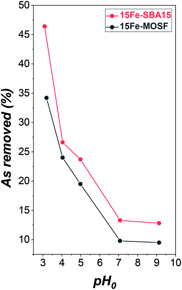 | ||
| Fig. 4 Adsorption capacity from batch adsorption experiments with 100 mg L−1 As(V) solution on iron oxide-silica adsorbents at different initial pH (pH0). 15Fe-MOSF is expressed in black, 15Fe-SBA15 in red. Conditions: 20 mL solution (ultrapure water or 100 mg L−1 As(V)), 100 mg 15Fe-MOSF or 15Fe-SBA15 sorbent dose, 25 °C, sorption time: 9 h shaking and 10 h resting. Further details on the adsorption experiments can be seen in Table S4 and Fig. S12.† | ||
Beyond iron oxides, amino groups are also proposed in the literature as promising arsenic binding sites in a broad range of pH.44–49 For this reason, the support of the composite featuring the best performance (SBA15) in terms of arsenic removal, was functionalized with (3-aminopropyl)triethoxysilane (APTES). CHN analyses permitted us to evaluate 2.5% of NH2 groups and 9.1% of propylamine, which correspond to about 34% w/w of APTES. The TGA curve of APTES-SBA15 (Fig. S13a†) from 25 °C to 850 °C under an O2 atmosphere reveals a two-step weight loss. The first one, ending at about 100 °C, is associated with water, while the second one, of about 10% weight loss and between 290 °C and 600 °C, is correlated with the loss of propylamine, in very good agreement with CHN data.92–95 The absence of weight loss at around 200 °C, typical of free APTES molecules (Fig. S13b†), suggests that all the APTES is covalently bonded to the silica surface. Moreover, the FTIR spectrum of APTES-SBA15 (Fig. S13c†) shows the vibrational modes typical of C–H stretching of CH3 and CH2 groups, besides those ascribable to the adsorbed water (OH stretching mode at ≈3450 cm−1, H–O–H bending mode at ≈1630 cm−1), and the silica support (Si–O–Si at ≈1200, 1080, 800 cm−1, Si–OH at ≈960 cm−1, and O–Si–O at ≈460 cm−1). Since the best performances of the composites were obtained at pH 3, the isotherms for the three sorbents were studied under the same pH value. At this pH value, the APTES-SBA15 is also expected to work better since the amino groups show the highest value of positive surface charge (about +28 mV at pH 3) in the selected range (pH 3–9), as indicated by the zeta potential vs. pH measurements (Fig. S14†).
The qevs. Ce plots (where qe was calculated by eqn (1)) at pH 3 for the three sorbents are shown in Fig. 5. The data are reported in Table S5† (Fig. S15† for the corresponding pH values). The data were fitted by different isotherm models, as indicated in the experimental section (Table 2): Langmuir (eqn (2)), Freundlich (eqn (3)), Temkin (eqn (4)), Redlich–Peterson (eqn (5)), and Dubinin-Radushkevich (eqn (6)).
 | ||
| Fig. 5 Sorption isotherms of As(V) on 15Fe-MOSF (a), 15Fe-SBA15 (b) and APTES-SBA15 (c). Conditions: pH = 3, 20 mL As(V) solution, 100 mg of sorbent dose, 25 °C, adsorption time: 9 hours shaking and subsequently 10 hours at rest. The isotherms were fitted by the Langmuir (blue), Freundlich (red), Temkin (green), Redlich–Peterson (pink), and Dubinin–Radushkevich (brown) model. The corresponding pH values of the adsorption experiments can be seen in Table S5 and Fig. S14.† | ||
| Sample | Isotherm | R 2 | K (*) | q m (mg g−1) | q m act (mg gact−1) | n | b T (J g mol−1 L−1) | α RP (L mg−1) | β RP | E ads (kJ mol−1) |
|---|---|---|---|---|---|---|---|---|---|---|
| 15Fe-MOSF | Langmuir | 0.86 | 0.3 | 5.5 | 36.7 | — | — | — | — | — |
| Freundlich | 0.93 | 2.1 | — | — | 0.2 | — | — | — | — | |
| Temkin | 0.96 | 81.5 | — | — | — | 4176 | — | — | — | |
| Redlich–Peterson | 0.95 | 31.5 | — | — | — | — | 11.1 | 0.9 | — | |
| Dubinin–Radushkevich | 0.82 | 3.5 | 5.3 | 35.3 | — | — | — | — | 0.38 | |
| 15Fe-SBA15 | Langmuir | 0.90 | 0.3 | 7.9 | 52.7 | — | — | — | — | — |
| Freundlich | 0.94 | 2.9 | — | — | 0.2 | — | — | — | — | |
| Temkin | 0.94 | 90.8 | — | — | — | 2962 | — | — | — | |
| Redlich–Peterson | 0.94 | 54.1 | — | — | — | — | 15.0 | 0.8 | — | |
| Dubinin–Radushkevich | 0.87 | 1.7 | 7.4 | 49.3 | — | — | — | — | 0.54 | |
| APTES-SBA15 | Langmuir | 0.95 | 0.04 | 12.4 | — | — | — | — | — | — |
| Freundlich | 0.96 | 1.8 | — | — | 0.4 | — | — | — | — | |
| Temkin | 0.97 | 0.55 | — | — | — | 1040 | — | — | — | |
| Redlich–Peterson | 0.98 | 0.66 | — | — | — | — | 0.09 | 0.9 | — | |
| Dubinin–Radushkevich | 0.87 | 20.3 | 9.2 | — | — | — | — | — | 0.16 |
Considering how the isotherm models describe the experimental data (i.e., how far or close the experimental points are with respect to the theoretical fitting curves derived by the different isotherm equations), together with the R2 values, the Freundlich model is the most appropriate to describe the sorption process, as also reported by other authors for similar systems,29–32,51 and, therefore, the surface of the composites is made of heterogeneous sites.96 Indeed, based on just R2 values it would have been concluded that Langmuir and Dubinin–Radushkevich models are not suitable, while the best fitting is reached for Temkin for 15Fe-MOSF, Freundlich, Temkin, and Redlich–Peterson for 15Fe-SBA15, and Redlich–Peterson for APTES-SBA15. Freundlich R2 is always not so far from the highest R2 also for 15Fe-MOSF (0.93 instead of 0.96) and APTES-SBA15 (0.96 instead of 0.98) samples, meaning that more than one isotherm model can be considered suitable. However, the first points in Fig. 5 in all experimental curves (range of Ce between 0 and 60 mg L−1) are better fitted by the Freundlich model for all samples, in particular, the point at about 30 mg L−1 for 15Fe-MOSF and 15Fe-SBA15. Even though the Langmuir and Dubinin–Radushkevich models are not the most suitable for the adsorption process presented here, they permit us to estimate the maximum adsorption capacity, which corresponds to 5.5–5.3 mg g−1 (37–35 mg gact−1), 7.9–7.4 mg g−1 (53–49 mg gact−1), 12.4–9.2 mg g−1 (41–31 mg gact−1) for 15Fe-MOSF, 15Fe-SBA15, and APTES-SBA15, respectively.
Among the tested adsorbents, better performances for the 15Fe-SBA15 composite were reached compared with the 15Fe-MOSF one, which can be again explained mainly by the reduced size of the active phase NPs deriving from smaller pores in the SBA-15 composite with respect to the MOSF one. Indeed, also other authors have reported a qm act (qm of the active phase) at pH 3 for 4 nm particles of about 50 mg g−1, which is comparable to that of the 15Fe-SBA15 sample with a similar maghemite particle size (5 nm) normalizing for the active phase mass (53–49 mg gact−1).91 The lower qm act value obtained for 15Fe-MOSF (37–35 mg g−1) agrees with the larger hematite particle size (18–20 nm) and the related lower surface area. These results highlight that the active phase (i.e., surface of the NPs) is completely accessible in both composites, suggesting that mesostructured materials are more suitable to disperse active phases with small NPs as adsorbents for water treatment.
The obtained qm values for APTES-SBA15, calculated by the Langmuir and Dubinin–Radushkevich isotherm models, correspond to 12.4 and 9.2 mg g−1, which is higher than those obtained by the iron oxide-based composites. The superior adsorption capacity of APTES-SBA15 in comparison with 15Fe-SBA15 can be due to the potential complete accessibility of the APTES groups. Indeed, for the iron oxide modified silica, only the groups on the surface of the Fe2O3 nanoparticles are accessible and contribute towards adsorption.
The adsorption kinetics were studied at pH 3 for the 15Fe-SBA15 and APTES-SBA15 sorbents in the contact time range 10–1140 min (initial As(V) concentration 10 mg L−1) (Table S6†). The qtvs. t plots (Fig. 6a) were fitted with the pseudo 1st and 2nd order models, also in the linearized forms (Fig. 6b and c). The APTES-SBA15 sorbent follows a pseudo 1st order model, as evidenced by the higher R2 and the closer theoretical adsorbed amount  if compared to the experimental one (qexpe) measured after 19 hours of testing (1.90 vs. 1.83 mg L−1). Moreover, the maximum loading is reached after 4 hours, indicating faster adsorption process with respect to 15Fe-SBA15. Indeed, in this latter sorbent, even though it features a pseudo 1st order behavior as can be seen in the linearized model (Fig. 6b), the kinetic constant is halved if compared to APTES-SBA15 (5.3 × 10⁻³vs. 10.5 × 10⁻³) and after 4 hours of testing only 40% of arsenic is removed. The pseudo 1st order kinetic model was found by other authors for iron oxide-based sorbents for arsenic and heavy metals removal.97 The qtvs. t0.5 plots (Fig. 6d) were fitted by the intraparticle diffusion model that, up to 240 minutes, accounts for one single diffusion mechanism. The faster adsorption rate of APTES-SBA15 is visible also in this case, and it is reflected in the rate constant (ki) of almost one order of magnitude higher (Table 3).
 | ||
| Fig. 6 Sorption kinetics of As(V) on 15Fe-SBA15 (red) and APTES-SBA15 (violet). Kinetics model fitting (a), linearized pseudo 1st order fitting (b), linearized pseudo 2nd model fitting (c), and intraparticle diffusion model fitting (d). Conditions: pH = 3, 20 mL As(V) solution, 100 mg of sorbent dose, 25 °C, adsorption time: 10–1140 minutes. | ||
| Sample | q expe (mg g−1) | Pseudo 1st order | Pseudo 2nd order | Intraparticle Diffusion Model | |||||
|---|---|---|---|---|---|---|---|---|---|
|
|
K′ (min−1) | R 2 |
|
K′′ (g mg−1 min−1) | R 2 | k i (g mg−1 min−0.5) | R 2 | ||
| 15Fe-SBA15 | 1.81 | 1.67 | 5.3 × 10⁻³ | 0.55 | 1.72 | 5.2 × 10⁻³ | 0.68 | 2.8 × 10⁻² | 0.80 |
| APTES-SBA15 | 1.83 | 1.90 | 10.5 × 10⁻³ | 0.98 | 2.16 | 5.5 × 10⁻³ | 0.94 | 1.5 × 10⁻¹ | 0.96 |


Silicon and iron release
The silicon release from all adsorbents was also monitored together with the iron release for the Fe2O3-based ones, since this issue is rarely investigated (Tables S4, S5,† and Fig. 7). Essentially, no iron is released (≤0.4 mg L−1) after the arsenic adsorption process with an initial arsenic concentration of about 100 mg L−1, in agreement with the results of Chen et al. that have already shown that for pH values above 3.30 The iron concentration decreased from 3–4 mg L−1 to 0.1 mg L−1 with increasing initial arsenic concentration. This behavior suggests that when the iron oxide binding sites are not saturated with arsenic species, iron ions can be released into the solution due to the acidic pH. On the contrary, when all the active sites are saturated, iron ions are stabilized due to the bonds with arsenic species (Scheme S1†).98–100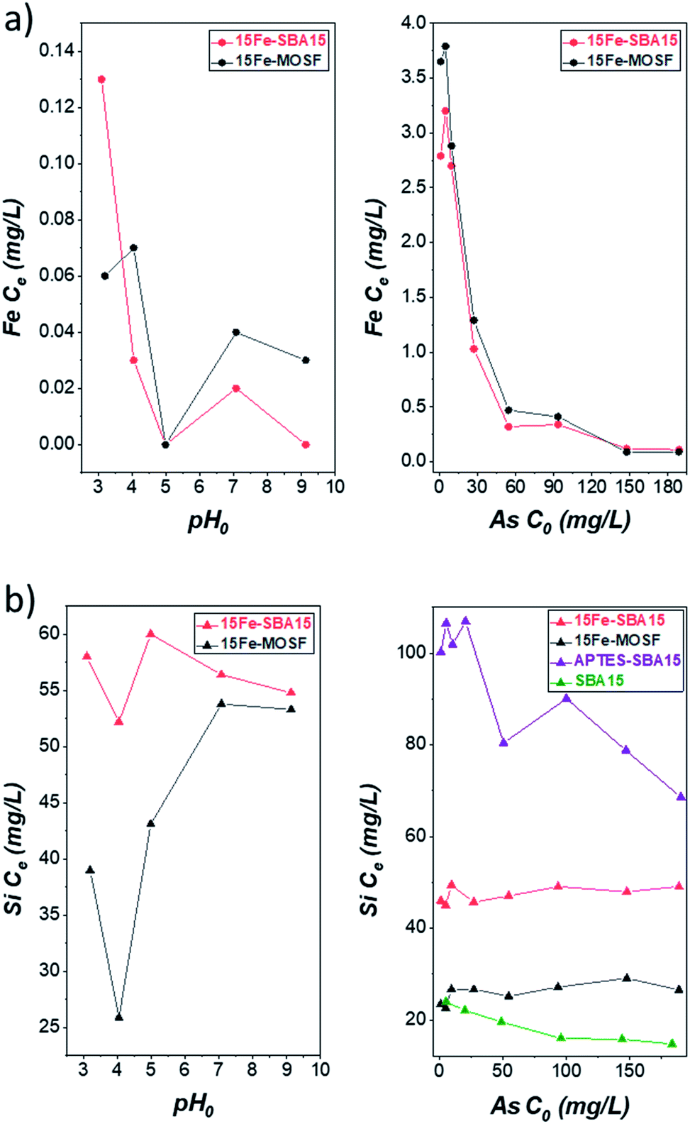 | ||
| Fig. 7 (a) Concentration of iron released after adsorption experiments with 100 mg L−1 As(V) at various pH (left) or at pH 3 at various initial arsenic concentrations (right). (b) Concentration of silicon released after adsorption experiments with 100 mg L−1 As(V) at various pH (left) or at pH 3 at various initial arsenic concentrations (right). Conditions: 20 mL solution, 100 mg 15Fe-MOSF, 15Fe-SBA15 or APTES-SBA15 sorbent dose, 25 °C, sorption time: 9 h shaking + 10 hours still. The corresponding pH values of the adsorption experiments can be seen in Table S4 and S5.† | ||
A noteworthy amount of silicon is detected for all adsorbents and under all adsorption conditions (from 23 to 107 mg L−1) (Fig. 7). A first comparison between the two Fe2O3-based sorbents for the adsorption tests at different pH reveals an almost constant silicon content for the 15Fe-SBA15 adsorbent, with values ranging from 52 to 60 mg L−1, and slightly lower silicon concentrations, with values in the range 26–54 mg L−1, in the case of 15Fe-MOSF (Table S4†), probably due to the lower surface area of the macroporous material. The silicon release was also monitored at pH 3 for different initial As(V) concentrations (Table S5†), revealing again higher silicon release for the 15Fe-SBA15 in comparison with the 15Fe-MOSF (45–49 mg L−1 against 23–29 mg L−1, respectively), with no trend as a function of the arsenic concentration, different to what was observed for the iron release. Since the iron release does not follow the trend in the detected silicon, it is possible to hypothesize that the released silica NPs do not contain iron oxide and are therefore not mesostructured. This setback might be overcome prior to the impregnation step by adopting a proper separation process (e.g., centrifugation or filtration) to remove the silica NPs. Unfortunately, the results related to the silicon release during the adsorption tests cannot be compared in the literature since only the arsenic adsorption performances are commonly evaluated.
To further investigate the release of silicon, SBA15 and 15Fe-SBA15 were placed in water with pH 5.5 and 3 (acidified with HCl) and processed as the adsorption samples (Table S7†). Firstly, all values for the silicon concentrations obtained at pH 3 are higher than those at pH 5.5, particularly for the 15Fe-SBA15 indicating that the pH has an effect when the support is modified with iron oxide NPs. Furthermore, the results compared with those acquired at different pH and initial arsenic concentration (Table S7†) indicate that: (i) the MOSF support and composite are responsible for the lowest silicon release, probably due to their lower surface area if compared to the SBA-based samples; (ii) the release in the 15Fe-MOSF sample is strongly dependent on the arsenic concentration, suggesting the role of the interaction between the arsenic species and the surface on this phenomenon; (iii) for SBA15, only a small effect from pH emerges, while there is no role of the arsenic concentration, as expected in the absence of an active phase; (iv) in the case of the 15Fe-SBA15, a higher averaged silicon concentration is observed in all the conditions with an active role of both the pH and arsenic concentration.
The highest silicon release is detected for the APTES-SBA15 sample, with values almost constant at about 100–107 mg L−1 for the initial As(V) concentration in the range 1–20 mg L−1, while as the As(V) concentration increases, the silicon content progressively lowers to about 70 mg L−1. TEM analysis on the residue of the supernatant deriving from one of the adsorption tests (APTES-SBA15, CAs = 5 mg L−1, pH 3; Fig. S16a†) shows that the silicon content in the solution is due to silica NPs (20–150 nm) released from the adsorbent during the removal tests. As a consequence of the repeated deposition of the diluted dispersion onto the TEM grid and the evaporation of the solvent, in some cases, it is possible to observe larger secondary entities (Fig. S16a†) made up of silica primary NPs. Furthermore, STEM-EDX analysis on the silica aggregated NPs, also in line profile, demonstrates the presence of silicon and oxygen in the NPs (Fig. S16b–g†) and the absence of nitrogen and arsenic (Fig. S16e†), suggesting that the silica NPs found in the supernatant are mainly not functionalized with APTES. Taking into account the intrinsic limitations of TEM analysis the presence of APTES-SBA15 nanoparticles cannot be completely excluded. A comparison with a non-grafted SBA15 sample was also performed to highlight possible effects deriving from organic or inorganic functionalization (Table S5†). In this case, values in the range 24–15 mg L−1 are observed with a progressive decrease of the silicon release with increasing initial As(V) concentration. The silicon release was found to follow the order: SBA15 < 15Fe-SBA15 < APTES-SBA15. This trend cannot be justified in terms of surface area (Table 1). Indeed, considering that SBA15 features the highest specific surface area, one should expect this sample to be responsible for the highest silicon release. Therefore, the inorganic/organic functionalization modifies the silica surface, affecting its stability in water. Moreover, an experiment conducted on APTES-SBA15 at pH 3 in the absence of arsenic species, revealed a halved silicon concentration if compared to those obtained with arsenic concentration in the range 1–20 mg L−1. These results suggest, as for the iron oxide-based sorbents, the strong role of adsorbed arsenic species on the silicon release phenomenon.
Conclusions
In this work, insight into the behaviour of silica-based adsorbents, grafted with iron oxide or amino groups as active phases and tested for arsenic removal, is provided by paying attention to (i) the role of the textural properties of the silica support, (ii) the role of the nature of the active phase; (iii) the occurrence of silicon secondary pollution phenomena. In detail, an Fe2O3-based mesostructured material (SBA15) has been compared with a macroporous one (MOSF), studying the effect of the pH and the initial concentration. The SBA15 sample features mesopores of about 7–8 nm and maghemite and hematite nanocrystals of about 4–6 nm, while the MOSF sample is formed by macropores of 70–120 nm containing both hematite nanocrystals with a size of 18–20 nm and maghemite of 3–5 nm. Both adsorbents showed better performance at lower pH (≈3), while the mesoporous sample revealed higher arsenic adsorption capacity (7.9 mg g−1) than that of the macroporous ones (5.5 mg g−1), mainly due to the smaller particle size and higher surface area. The SBA15 sample was compared with a hybrid organic-inorganic adsorbent, i.e., SBA15 functionalized with APTES (2.5% w/w NH2). This latter sample features a higher adsorption capacity and faster kinetics than the iron oxide-based counterpart (12.4 mg g−1). The use of the Fe2O3-based samples does not lead to iron release (<0.4 mg L−1). However, silicon leaking was detected for all samples, probably caused by the detachment of silica nanoparticles from the material. The silicon content was found to be dependent on the surface area (mesostructured > macrostructured), the pH (3 > 5), the post-synthesis surface grafting (grafted > non-grafted), the type of functionalization (organic > inorganic), and the arsenic concentration for the composites.Conflicts of interest
There are no conflicts to declare.Acknowledgements
This work was supported by the German research foundation BMBF (Bundesministerium für Bildung und Forschung), project ISOMAT (Project No. 01DS18022). We thank Dr Simona Schwarz for the particle size measurements and fruitful discussions. CESA project RAS-Piano Sulcis, PON AIM (PON Ricerca e Innovazione 2014–2020 – Azione I.2 – DD n. 407 del 27 febbraio 2018 “Attraction and International Mobility”, CultGeoChim project AIM1890410-3), and Fluorsid S.p.A. are gratefully acknowledged for financing the fellowships of M. Sanna Angotzi, V. Mameli, and C. Cara, respectively. The University of Cagliari (UniCA) and Fondazione di Sardegna (FdS) are acknowledged for the financial support – Project: CUP F72F20000240007(2019): “Surface-tailored Materials for Sustainable Environmental Applications”. We acknowledge the CeSAR (Centro Servizi d’Ateneo per la Ricerca) of the University of Cagliari, Italy, for the TEM, HRTEM and PPMS measurements performed with JEOL JEM 1400 PLUS, JEOL JEM 2010 UHR and PPMS Dynacool by Quantum Design.References
- T. G. Asere, C. V. Stevens and G. Du Laing, Sci. Total Environ., 2019, 676, 706–720 CrossRef CAS PubMed.
- World Health Organization, Guidelines for Drinking-water Quality, World Health Organization, 4th edn, 2017 Search PubMed.
- L. Hao, M. Liu, N. Wang and G. Li, RSC Adv., 2018, 8, 39545–39560 RSC.
- P. A. O’Day, Elements, 2006, 2, 77–83 CrossRef.
- B. Liu, K. H. Kim, V. Kumar and S. Kim, J. Hazard. Mater., 2020, 388, 121815 CrossRef CAS PubMed.
- C. B. Tabelin, T. Igarashi, M. Villacorte-Tabelin, I. Park, E. M. Opiso, M. Ito and N. Hiroyoshi, Sci. Total Environ., 2018, 645, 1522–1553 CrossRef CAS PubMed.
- A. Dadwal and V. Mishra, Clean: Soil, Air, Water, 2017, 45, 1600364 Search PubMed.
- R. Singh, S. Singh, P. Parihar, V. P. Singh and S. M. Prasad, Ecotoxicol. Environ. Saf., 2015, 112, 247–270 CrossRef CAS PubMed.
- N. R. Nicomel, K. Leus, K. Folens, P. Van Der Voort and G. Du Laing, Int. J. Environ. Res. Public Health, 2015, 13, 1–24 CrossRef PubMed.
- S. Shankar, U. Shanker and Shikha, Sci. World J., 2014, 2014, 1–18 CrossRef PubMed.
- S. Rahman, K. H. Kim, S. K. Saha, A. M. Swaraz and D. K. Paul, J. Environ. Manage., 2014, 134, 175–185 CrossRef CAS PubMed.
- S. Bolisetty, M. Peydayesh and R. Mezzenga, Chem. Soc. Rev., 2019, 48, 463–487 RSC.
- M. Gallegos-Garcia, K. Ramírez-Muñiz and S. Song, Miner. Process. Extr. Metall. Rev., 2012, 33, 301–315 CrossRef CAS.
- L. Yan, S. Hu and C. Jing, J. Environ. Sci., 2016, 49, 74–85 CrossRef CAS PubMed.
- D. E. Giles, M. Mohapatra, T. B. Issa, S. Anand and P. Singh, J. Environ. Manage., 2011, 92, 3011–3022 CrossRef CAS PubMed.
- C. K. Jain and R. D. Singh, J. Environ. Manage., 2012, 107, 1–18 CrossRef CAS PubMed.
- P. Song, Z. Yang, G. Zeng, X. Yang, H. Xu, L. Wang, R. Xu, W. Xiong and K. Ahmad, Chem. Eng. J., 2017, 317, 707–725 CrossRef CAS.
- T. Marino and A. Figol, Membranes, 2015, 5, 150–167 CrossRef CAS PubMed.
- V. T. Luong, E. E. Cañas Kurz, U. Hellriegel, T. L. Luu, J. Hoinkis and J. Bundschuh, Water Res., 2018, 133, 110–122 CrossRef CAS PubMed.
- M. Kobya, R. D. C. Soltani, P. I. Omwene and A. Khataee, Environ. Technol. Innovation, 2020, 17, 100519 CrossRef.
- J. Q. Jiang, S. M. Ashekuzzaman, A. Jiang, S. M. Sharifuzzaman and S. R. Chowdhury, Int. J. Environ. Res. Public Health, 2012, 10, 18–46 CrossRef PubMed.
- D. Haldar, P. Duarah and M. K. Purkait, Chemosphere, 2020, 251, 126388 CrossRef CAS PubMed.
- C. Wang, J. Luan and C. Wu, Water Res., 2019, 158, 370–382 CrossRef CAS PubMed.
- S. Lata and S. R. Samadder, J. Environ. Manage., 2016, 166, 387–406 CrossRef CAS PubMed.
- A. Sarkar and B. Paul, Chemosphere, 2016, 158, 37–49 CrossRef CAS PubMed.
- S. I. Siddiqui, M. Naushad and S. A. Chaudhry, Process Saf. Environ. Prot., 2019, 126, 60–97 CrossRef CAS.
- W. Wong, H. Y. Wong, A. B. M. Badruzzaman, H. H. Goh and M. Zaman, Nanotechnology, 2017, 28, 042001–31 CrossRef PubMed.
- L. Chen, H. Xin, Y. Fang, C. Zhang, F. Zhang, X. Cao, C. Zhang and X. Li, J. Nanomater., 2014, 2014, 1–10 Search PubMed.
- G. Li, J. Lan, J. Liu and G. Jiang, J. Colloid Interface Sci., 2013, 405, 164–170 CrossRef CAS PubMed.
- X. Chen, K. F. Lam, Q. Zhang, B. Pan, M. Arruebo and K. L. Yeung, J. Phys. Chem. C, 2009, 113, 9804–9813 CrossRef CAS.
- X. Peng, Y. Zhao, T. Yang, Y. Yang, Y. Jiang, Z. Ma, X. Li, J. Hou, B. Xi and H. Liu, Microporous Mesoporous Mater., 2018, 258, 26–32 CrossRef CAS.
- F. Li, Microporous Mesoporous Mater., 2013, 171, 139–146 CrossRef CAS.
- C. Cara, A. Musinu, V. Mameli, A. Ardu, D. Niznansky, J. Bursik, M. a. Scorciapino, G. Manzo and C. Cannas, Cryst. Growth Des., 2015, 15, 2364–2372 CrossRef CAS.
- M. Sanna Angotzi, V. Mameli, C. Cara, A. Ardu, D. Nizňnanský and A. Musinu, J. Nanosci. Nanotechnol., 2019, 19, 4954–4963 CrossRef PubMed.
- V. Mameli, M. Sanna Angotzi, C. Cara and C. Cannas, J. Nanosci. Nanotechnol., 2019, 19, 4857–4887 CrossRef PubMed.
- Y. Georgiou, I. T. Papadas, E. Mouzourakis, E. Skliri, G. S. Armatas and Y. Deligiannakis, Environ. Sci.: Nano, 2019, 6, 1156–1167 RSC.
- B. Zhi, H. Ding, D. Wang, Y. Cao, Y. Zhang, X. Wang, Y. Liu and Q. Huo, J. Mater. Chem. A, 2014, 2, 2374–2382 RSC.
- Y. M. Wang, Z. Y. Wu, L. Y. Shi and J. H. Zhu, Adv. Mater., 2005, 17, 323–327 CrossRef CAS.
- P. Westerhoff, D. Highfield, M. Badruzzaman and Y. Yoon, J. Environ. Eng., 2005, 131, 262–271 CrossRef CAS.
- A. Arencibia, M. S. López-Gutiérrez and J. M. Arsuaga, J. Chem. Technol. Biotechnol., 2020, 2019, 6339 Search PubMed.
- M. Hasanzadeh, F. Farajbakhsh, N. Shadjou and A. Jouyban, Environ. Technol., 2015, 36, 36–44 CrossRef CAS PubMed.
- M. Hasanzadeh, F. Farajbakhsh, N. Shadjou and A. Jouyban, Environ. Technol., 2015, 36, 36–44 CrossRef CAS PubMed.
- E. McKimmy, J. Dulebohn, J. Shah and T. J. Pinnavaia, Chem. Commun., 2005, 3697–3699 RSC.
- H. Yoshitake, T. Yokoi and T. Tatsumi, Chem. Mater., 2002, 14, 4603–4610 CrossRef CAS.
- A. Benhamou, J. P. Basly, M. Baudu, Z. Derriche and R. Hamacha, J. Colloid Interface Sci., 2013, 404, 135–139 CrossRef CAS PubMed.
- Y. Wu, Y. Jin, J. Cao, P. Yilihan, Y. Wen and J. Zhou, J. Ind. Eng. Chem., 2014, 20, 2792–2800 CrossRef CAS.
- H. Yoshitake, E. Koiso, H. Horie and H. Yoshimura, Microporous Mesoporous Mater., 2005, 85, 183–194 CrossRef CAS.
- M. H. Dindar, M. R. Yaftian and S. Rostamnia, J. Environ. Chem. Eng., 2015, 3, 986–995 CrossRef CAS.
- M. H. Dindar, M. R. Yaftian, M. Hajihasani and S. Rostamnia, J. Taiwan Inst. Chem. Eng., 2016, 67, 325–337 CrossRef CAS.
- T. Kamegawa, Y. Ishiguro, H. Seto and H. Yamashita, J. Mater. Chem. A, 2015, 3, 2323–2330 RSC.
- J. Yang, H. Zhang, M. Yu, I. Emmanuelawati, J. Zou, Z. Yuan and C. Yu, Adv. Funct. Mater., 2014, 24, 1354–1363 CrossRef CAS.
- N. D. Thorat, J. Bauer, S. A. M. Tofail, V. Gascón Pérez, R. A. Bohara and H. M. Yadav, Colloids Surf., B, 2020, 185, 110571 CrossRef CAS PubMed.
- H. Wang, X. Rong, L. Han, M. Tang, M. Yu, J. Zhang, W. Huang and R. Chen, RSC Adv., 2015, 5, 5695–5703 RSC.
- J. Zhang, M. Yu, P. Yuan, H. Wang, K. Qian, L. Tan, Y. Wang and C. Yu, J. Mater. Res., 2010, 25, 648–657 CrossRef CAS.
- J. Wan, K. Qian, L. Qiao, Y. Wang, J. Kong, P. Yang, B. Liu and C. Yu, Chem.–Eur. J., 2009, 15, 2504–2508 CrossRef CAS PubMed.
- K. Qian, J. Wan, L. Qiao, X. Huang, J. Tang, Y. Wang, J. Kong, P. Yang, C. Yu and B. Liu, Anal. Chem., 2009, 81, 5749–5756 CrossRef CAS PubMed.
- J. Yang, P. Yuan, H. Y. Chen, J. Zou, Z. Yuan and C. Yu, J. Mater. Chem., 2012, 22, 9983–9990 RSC.
- X. Cao, Y. Sun, Y. Ye, Y. Li and X. Ge, Anal. Methods, 2014, 6, 1448–1454 RSC.
- C. Zhao, J. Yang and B. Jiang, RSC Adv., 2017, 7, 47225–47234 RSC.
- M. Baikousi, A. B. Bourlinos, A. Douvalis, T. Bakas, D. F. Anagnostopoulos, J. Tuček, K. Šafářová, R. Zboril and M. A. Karakassides, Langmuir, 2012, 28, 3918–3930 CrossRef CAS PubMed.
- H. Wang, X. Zhou, M. Yu, Y. Wang, L. Han, J. Zhang, P. Yuan, G. Auchterlonie, J. Zou and C. Yu, J. Am. Chem. Soc., 2006, 128, 15992–15993 CrossRef CAS PubMed.
- G. Liu, R. Yang and M. Li, J. Non-Cryst. Solids, 2010, 356, 250–257 CrossRef CAS.
- J. Pan, J. Zeng, Q. Cao, H. Gao, Y. Gen, Y. Peng, X. Dai and Y. Yan, Chem. Eng. J., 2016, 284, 1361–1372 CrossRef CAS.
- A. Walcarius, M. Etienne and B. Lebeau, Chem. Mater., 2003, 15, 2161–2173 CrossRef CAS.
- V. Manu, H. M. Mody, H. C. Bajaj and R. V. Jasra, Ind. Eng. Chem. Res., 2009, 48, 8954–8960 CrossRef CAS.
- A. Walcarius, M. Etienne and J. Bessière, Chem. Mater., 2002, 14, 2757–2766 CrossRef CAS.
- F. Younas, A. Mustafa, Z. U. R. Farooqi, X. Wang, S. Younas, W. Mohy-Ud-Din, M. Ashir Hameed, M. Mohsin Abrar, A. A. Maitlo, S. Noreen and M. M. Hussain, Water, 2021, 13, 215 CrossRef CAS.
- L. Chen, J. Liu, Y. Zhang, G. Zhang, Y. Kang, A. Chen, X. Feng and L. Shao, Nanomedicine, 2018, 13, 1939–1962 CrossRef PubMed.
- D. Napierska, L. C. J. Thomassen, V. Rabolli, D. Lison, L. Gonzalez, M. Kirsch-Volders, J. A. Martens and P. H. Hoet, Small, 2009, 5, 846–853 CrossRef CAS PubMed.
- N. Malhotra, J.-S. Lee, R. A. D. Liman, J. M. S. Ruallo, O. B. Villaflores, T.-R. Ger and C.-D. Hsiao, Molecules, 2020, 25, 3159 CrossRef CAS PubMed.
- D. Zhao, J. Feng, Q. Huo, M. Nicholas, G. H. H. Fredrickson, B. F. F. Chmelka, G. D. D. Stucky, N. Melosh, G. H. H. Fredrickson, B. F. F. Chmelka and G. D. D. Stucky, Science, 1998, 279, 548–552 CrossRef CAS PubMed.
- C. Cara, E. Rombi, A. Musinu, V. Mameli, A. Ardu, M. Sanna Angotzi, L. Atzori, D. Niznansky, H. L. Xin and C. Cannas, J. Mater. Chem. A, 2017, 5, 21688–21698 RSC.
- C. Cara, E. Rombi, V. Mameli, A. Ardu, M. Sanna Angotzi, D. Niznansky, A. Musinu and C. Cannas, J. Phys. Chem. C, 2018, 122, 12231–12242 CrossRef CAS.
- I. Langmuir, J. Am. Chem. Soc., 1916, 38, 2221–2295 CrossRef CAS.
- H. Freundlich, Z. Phys. Chem., 1907, 57U, 385–470 CrossRef.
- M. I. Temkin and V. Pyzhev, Acta Physicochim. URSS, 1940, 12, 327 CAS.
- O. Redlich and D. L. Peterson, J. Phys. Chem., 1959, 63, 1024 CrossRef CAS.
- M. M. Dubinin and L. V. Radushkevich, Doklady Akademii Nauk, 1947, 15, 327–329 Search PubMed.
- H. Freundlich, Zeitschrift für Chemie und Ind. der Kolloide, 1907, 2, 15 Search PubMed.
- T. R. Sahoo and B. Prelot, Adsorption processes for the removal of contaminants from wastewater, Elsevier Inc., 2020 Search PubMed.
- T. A. S. Ferreira, J. C. Waerenborgh, M. H. R. M. Mendonça, M. R. Nunes and F. M. Costa, Solid State Sci., 2003, 5, 383–392 CrossRef CAS.
- L. Lutterotti and P. Scardi, J. Appl. Crystallogr., 1990, 23, 246–252 CrossRef CAS.
- R. A. Young and D. B. Wiles, J. Appl. Crystallogr., 1982, 15, 430–438 CrossRef CAS.
- V. Montoro, Gazz. Chim. Ital., 1938, 68, 728–733 CAS.
- J. Rouquerol, R. Françoise, L. Phillip, M. Guillaume and S. Kenneth, Adsorption by Powders and Porous Solids, Elsevier, 2nd edn, 1999 Search PubMed.
- C. Cara, V. Mameli, E. Rombi, N. Pinna, M. Sanna Angotzi, D. Nižňanský, A. Musinu and C. Cannas, MicroporousMesoporous Mater., 2020, 298, 110062 CrossRef CAS.
- M. A. Vacca, C. Cara, V. Mameli, M. Sanna Angotzi, M. A. Scorciapino, M. G. Cutrufello, A. Musinu, V. Tyrpekl, L. Pala and C. Cannas, ACS Sustainable Chem. Eng., 2020, 8, 14286–14300 CrossRef CAS.
- C. Cara, E. Rombi, A. Ardu, M. A. Vacca and C. Cannas, J. Nanosci. Nanotechnol., 2019, 19, 5035–5042 CrossRef CAS PubMed.
- M. Mureddu, I. Ferino, A. Musinu, A. Ardu, E. Rombi, M. G. Cutrufello, P. Deiana, M. Fantauzzi and C. Cannas, J. Mater. Chem. A, 2014, 2, 19396–19406 RSC.
- M. Mureddu, I. Ferino, E. Rombi, M. G. Cutrufello, P. Deiana, A. Ardu, A. Musinu, G. Piccaluga and C. Cannas, Fuel, 2012, 102, 691–700 CrossRef CAS.
- T. Tuutijärvi, J. Lu, M. Sillanpää and G. Chen, J. Hazard. Mater., 2009, 166, 1415–1420 CrossRef PubMed.
- W. Qin, F. Vautard, P. Askeland, J. Yu and L. Drzal, RSC Adv., 2015, 5, 2457–2465 RSC.
- Y. Zhang, F. Gao, B. Wanjala, Z. Li, G. Cernigliaro and Z. Gu, Appl. Catal., B, 2016, 199, 504–513 CrossRef CAS.
- D. Maity, P. Chandrasekharan, S. Feng and D. Jun, 2010 Int. Conf. Nanosci. Nanotechnol., 2010, pp. 94–97 Search PubMed.
- L. Ma, N. Li, J. Zhu and X. Chen, Polymers, 2017, 9, 58 CrossRef CAS PubMed.
- C. A. Ghiorghita, F. Bucatariu and E. S. Dragan, Cellulose Chem. Technol., 2018, 52, 663–672 CAS.
- E. Shabani, F. Salimi and A. Jahangiri, Silicon, 2019, 11, 961–971 CrossRef CAS.
- Z. Liu, J. Chen, Y. Wu, Y. Li, J. Zhao and P. Na, J. Hazard. Mater., 2018, 343, 304–314 CrossRef CAS PubMed.
- C. Y. Cao, J. Qu, W. S. Yan, J. F. Zhu, Z. Y. Wu and W. G. Song, Langmuir, 2012, 28, 4573–4579 CrossRef CAS PubMed.
- M. D’Arcy, D. Weiss, M. Bluck and R. Vilar, J. Colloid Interface Sci., 2011, 364, 205–212 CrossRef PubMed.
Footnotes |
| † Electronic supplementary information (ESI) available. See DOI: 10.1039/d1na00487e |
| ‡ These authors equally contributed to the work. |
| This journal is © The Royal Society of Chemistry 2021 |