 Open Access Article
Enhanced broadband absorption with a twisted multilayer metal–dielectric stacking metamaterial†
Guangsheng
Deng
 *ab,
Hanxiao
Sun
a,
Kun
Lv
a,
Jun
Yang
 *ab,
Zhiping
Yin
ab,
Ying
Li
ab and
Baihong
Chi
c
aSpecial Display and Imaging Technology Innovation Center of Anhui Province, Academy of Opto-Electric Technology, Hefei University of Technology, Hefei, 230009, China. E-mail: dgsh@hfut.edu.cn; junyang@hfut.edu.cn
bAnhui Province Key Laboratory of Measuring Theory and Precision Instrument, School of Instrument Science and Optoelectronics Engineering, Hefei University of Technology, Hefei, 230009, China
cProcess and Mechanical Engineering Technology Laboratory, Space Star Technology Co. Ltd, Beijing, 100095, China
First published on 6th July 2021
Abstract
This study proposes and experimentally demonstrates enhanced broadband absorption with twisted multilayer metal–dielectric stacking. Compared with the traditional metal–dielectric pyramid, the resonance frequencies of the third-order magnetic resonances in the twisted quadrangular frustum redshifted obviously. Hence, the proposed structure enables an ultra-broadband absorption by combining the third-order magnetic resonances with the fundamental mode. The broadband absorption is insensitive to the incident wave polarization, whereas the twisted angle of the stacking plays an important role in deciding the absorption bandwidth. The sample was fabricated via the multi-material hybrid micro-droplet jetting modeling (MHMJM) technology to verify the enhanced absorbing performance. The measured results suggest that the proposed strategy provides a potential path to realize broadband electromagnetic wave absorption. Moreover, it is possible to extend the twisted metamaterial to the terahertz and infrared frequencies using the advanced nano fabrication techniques.
Introduction
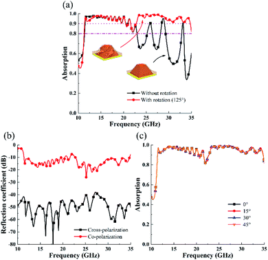
Electromagnetic metamaterial absorbers (MAs)1,2 are artificial sub-wavelength structures that possess efficient attenuation ability of an electromagnetic wave over a broad frequency band and have attracted considerable attention in both civil and military applications.3–5 Compared with the traditional absorbers, MAs break the bulk limitation, which is important for miniaturization and light-weight design.6,7 As an important subtype of MAs, the broadband MAs enable wideband electromagnetic wave absorption with high absorptivity as required in numerous applications such as energy harvesting,8–10 radar cross-section reduction,11 and stealth technology.12,13 Hence, many efforts have been made towards the broadening of absorption bandwidth over the past decade.14,15 One method is to pack several resonance structures into a super unit cell (planar arrangement). However, the combination of a single resonant peak will inevitably lead to the severe fluctuation of absorption within the desired bandwidth.16–18 To flatten the absorption spectrum of broadband MAs, another method is to vertically align the multilayer patterns (vertical arrangement) to superpose a series of narrow-band absorption peaks in order to form a broadband absorption.19–22 Moreover, the superposed structure also reduces the unit size compared with the planar arrangement method. Particularly, the multilayer metal–dielectric structure is a simple and effective solution to broaden the absorption bandwidth.23 In 2012, Ding et al. reported a broadband MA with quadrangular frustum pyramids using metal–dielectric multilayers, which realized broadband absorption in 8–14 GHz.24 Mo et al. and Kim et al. demonstrated truncated cone MAs with metal–dielectric multilayer structures that achieved broadband absorption in terahertz and microwave frequency range, respectively.25,26 This vertical arrangement method is based on the combination of, numerous fundamental resonances at different positions of the frustum pyramid from bottom to the top layer. However, simply increasing the layers cannot further broaden the absorption bandwidth due to the height limitation of pyramid structures. Recently, curve altitude pyramid structures that utilize the curve line as the pyramid's hypotenuse have been proposed to broaden the absorption bandwidth.27 However, compared with the multilayer pyramid MA, the curve altitude pyramid structure needs larger height and size, causing difficulty in practical applications.The investigation of unusual electronic and polariton phenomena observed in twisted stacks of two-dimensional materials has become a hot-spot in the community.28–30 The twisted stacking structures enable exotic dispersion engineering and enhanced light–matter interactions.31,32 Inspired by the idea of twisted magic angle and the popularity of three-dimensional structures,33,34 a new method is proposed to enhance the absorption bandwidth of multilayer metal–dielectric stacking metamaterials in this study. By individually rotating each stacking layer along the vertical symmetry axis at a certain angle, the absorption bandwidth of the proposed structure at a higher frequency region can be effectively enlarged. In the simulation, the designed conventional un-twisted pyramid absorber (PA) can realize wideband absorption from 11.39 to 20.46 GHz with absorptivity above 90%. In contrast, the introduction of a layer-by-layer rotation of the metallic square patch enables the proposed twisted pyramid absorber (TPA) to exhibit an ultra-wideband absorption in the frequency band of 22.76–34.76 GHz with absorptivity greater than 90%. Through the magnetic field analysis of TPA, the absorption at a lower frequency band turns out to be induced by the fundamental magnetic resonances, which are similar to the pyramid absorber. However, the broadband absorption of TPA at the high-frequency region is originated from the third-order magnetic resonances as these discrete resonances at different parts within the twisted structure can be excited together to cover a broader range. To experimentally validate the proposed strategy, the sample was fabricated using the multi-material hybrid micro-droplet jetting modeling (MHMJM) technology and the measured results reveal that the TPA enables extra broadband absorption and can achieve absorption above 80% within the frequency range of 11.3–35.0 GHz. Hence, the proposed approach, which is compatible with 3D printing, paves an effective way in broadening the absorption bandwidth of the MA.
Configuration of the stereo structure
Fig. 1(a) shows the schematic of the unit cell of the pyramid absorber consisting of 20 metallic patches with thickness w1. The metallic patches are vertically arranged with side inclination angle α and each layer is isolated by a dielectric substrate with thickness w2. Fig. 1(c) illustrates the unit cell of the proposed TPA after rotating the stacking layers along the vertical symmetry axis with angle β. The dielectric substrate, composed of a cuboid and a truncated cone, is the same for both PA and TPA. Fig. 1(b) illustrates the detailed structural parameters of the pyramid absorber with optimized values of: p = 8.9, q = 7.2, cdown = 8.8, cup = 4.2, α = 60°, t = 0.017, w1 = 0.02, w2 = 0.18, h1 = 1.2, and h2 = 2.8 mm. Fig. 1(d) depicts the top view of TPA. Compared with those of PA, the metallic layers of the proposed TPA have rotated counter clockwise with a total angle of 125°, while the adjacent layers of TPA keep a constant rotation angle of nearly 6.58°. In the simulation, the employed metallic layers are assumed to be sliver paste with the electrical conductivity of 5.88 × 10⁵ S m−1, whereas the dielectric substrate is a photosensitive resin with the relative permittivity of 2.9 and the loss tangent of 0.02.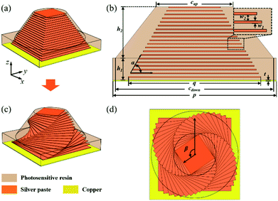 | ||
| Fig. 1 (a) The layout of the PA. (b) The side view of the PA unit cell. (c) The layout of the proposed TPA. (d) The top view of the proposed TPA. | ||
Numerical calculations were performed via the finite element method (FEM). In the simulation, the periodic boundary conditions were used for both x- and y-directions, while open boundary condition was employed in the z-direction. Due to the existence of ground plane, the absorption A of the MA can be calculated from the reflection coefficient S11 by A(w) = 1 − |S11(w)|2. Moreover, the TE-polarization is defined by the incident wave with electric field parallel to the x-axis, corresponding to the polarization angle of 0°. Fig. 2(a) shows the simulated absorption spectra of the designed PA and TPA. It can be seen that for the lower frequency region (11.39–20.46 GHz), the absorption spectrum of TPA coincided with that of PA as the absorptivity maintains above 90%. However, compared with PA, TPA has an extra absorption band from 22.76 to 34.76 GHz with high absorptivity. The reason is that the two absorption bands can combine to form an ultra-broadband absorption from 11.3 GHz to 35.0 GHz, with the relative absorption bandwidth of 102.4%. The simulated cross- and co-polarization reflection coefficients shown in Fig. 2(b) indicate that the polarization conversion in the proposed TPA is negligible. Furthermore, Fig. 2(c) shows that TPA is insensitive to the incident wave polarization as the multilayer structure is still symmetric after twisting.
Table 1 depicts the absorption spectrum of TPA with some reported PAs. By twisting the stacking layers, the absorption bandwidth can be significantly enhanced without increasing the volume of the unit cell structure.
| Stacking type | Thickness (mm) | Unit cell (mm2) | Absorbing frequency with absorptivity >90% (GHz) | Reference |
|---|---|---|---|---|
| Pyramid | 5.5 | 12 × 12 | 8–12 | 23 |
| Pyramid | 5 | 11 × 11 | 7.8–14.7 | 24 |
| 2 pyramids in a super unit cell | 4.36 | 24 × 24 | 7–18 | 35 |
| 4 pyramids in a super unit cell | 4.134 | 22.2 × 22.2 | 7–21.5 | 36 |
| Twisted pyramid | 4 | 8.9 × 8.9 | 11.39–20.46/22.76–34.76 | This work |
Simulation and discussion
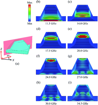
To study the mechanism of the twisted structure in broadening the absorption bandwidth, the magnetic-field profiles for TE-polarized excitation were simulated. Fig. 3 shows the magnetic-field intensities at eight different frequencies (11.5, 14.0, 17.5, 20.0, 24.0, 27.0, 30.0, and 34.5 GHz). Particularly, Fig. 3(b)–(e) represent the magnetic-field distribution at the lower frequency band. For these resonance frequencies, the magnetic field is concentrated in the center of the metal patch arrays as these resonant modes can be defined as fundamental magnetic resonances. It can be seen from Fig. 3(b) that the field distribution of fundamental magnetic resonance is located at the bottom and diffuses into several layers nearby, indicating that the fundamental magnetic resonance at 11.5 GHz is co-excited by bottom neighboring layers like some mini-resonators with subtle width difference. Fig. 3(c)–(e) show that with the increase in frequency, the concentration of the magnetic field moves from the bottom to the top of the pyramid. Therefore, the combination of numerous fundamental magnetic resonances forms the broadband absorption at the frequency range of 11.39–20.46 GHz. In general, both the intensity and location of the fundamental magnetic resonances in TPA and PA are exactly the same as the two structures share nearly identical absorption spectrum in the lower frequency region shown in Fig. 2(a).Moreover, Fig. 3(f)–(i) show the magnetic field distributions in TPA in the higher absorption frequency band (22.76–34.76 GHz). At 24.0 GHz, it can be observed that besides the fundamental magnetic resonances located at the top of the twisted pyramid, the third-order magnetic resonances are also excited at the bottom layers. Hence, the induced surface currents do not only flow to the bottom layers due to the third-harmonic resonances but also to the top layers originated from the fundamental modes. The top and bottom patches with accumulated charges act as metallic layers of the capacitor, which lead to a strong dielectric loss in the dielectric layer between the two metallic planes.26 Moreover, the magnetic field distribution of both the modes gradually moves towards the upper portion of the structure with the increase in frequency. Finally, the fundamental mode evanesces over 34.5 GHz (see Fig. 3(i)); thus, the dielectric loss as well as the absorption of TPA decreases rapidly.
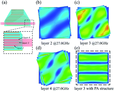
It is well known that the resonance frequency of third-order resonances is approximately three times higher than that of the fundamental mode. However, in the TPA structure, the location of third-order resonances shows an evident redshift. To further investigate this phenomenon, we simulated the magnetic field distribution on the surface of some adjacent stacking patches at 27.0 GHz and the results are shown in Fig. 4. As shown in Fig. 4(b)–(d), the magnetic field represents as three stripes is originated from the third-order resonances. Furthermore, the distribution of magnetic field is mainly along the diagonal line of the square patch under TE-polarized incidence, which is very different from the circumstances in traditional PA structures. The typical magnetic field distribution of third-order resonance in the non-twisted PA structure is shown in Fig. 4(e). Compared with the non-twisted PA structure, the M-field spot on TPA's patch is much larger. Hence, the resonance frequency of the third-order mode in TPA is much lower than that in PA, which enables its coupling with the fundamental modes within a broadband region (22.0–35.0 GHz) and finally leads to an extra broadband absorption.
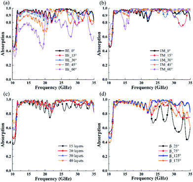
The absorption performance of proposed TPA for oblique incidences was investigated. Fig. 5(a) and (b) show the simulated absorption spectra at different angles of incidence for both TE and TM polarizations. From Fig. 5(a), the absorption for TE polarization almost maintains above 70% in the entire operation band with the incident angle up to 45°. For the case of TM polarization shown in Fig. 5(b), TPA exhibits high incident wave absorption in a broadband frequency band even with the wave incident angle reaching up to 60°. Hence, the extra absorption band of TPA at a higher frequency region originated from high-order magnetic resonances is still insensitive to both the TE- and TM-polarized oblique incidences for a wide range of incident angles compared with the fundamental magnetic resonances. In addition, the electric field excited by TE polarization wave will decrease with the increase in the incidence angle, which reduces the absorption. However, the electric filed excited by the TM polarization wave is insensitive to the angles.
Next, the influence of the number of metallic patch layers and the total rotation angle of the twisted pyramid β on the TPA's absorption spectrum is discussed. Fig. 5(c) depicts the absorption spectra for different numbers of metallic patch layers. As discussed previously, the fundamental and high-order magnetic resonances are excited within several neighbouring layers. For a fixed height of TPA, the pyramid with 15 metal patch layers indicates a relatively large width difference between the adjacent metal patches; hence, the resonances are discrete within the absorption band. However, when the number of metallic layers increases to 40, increased magnetic resonances on the patches lead to smooth and effective wave absorption. Fig. 5(d) shows the influence of the rotation angle β on the absorption spectrum of the proposed TPA. It can be seen from the figure that absorption within the lower frequency band, in other words, the fundamental magnetic resonances, are insensitive to the rotation angle β. However, β has a significant impact on the absorption spectrum at the higher frequency band. Both the absorption bandwidth and absorptivity are enhanced to a maximum with the increase in β. However, the continuous increase in the rotation angle β will lead to a decrease in the absorbing performance of TPA. The reason for this phenomenon is as follows: at the initial state, when β increases, the coupling between these adjacent metallic square patches will excite high order resonance at higher frequencies. At a rotation angle β of 125°, there is best coupling match between the adjacent layers, which leads to a strong and smooth absorption at a higher frequency band. However, the mismatch of the neighbouring patches becomes worse with the further increase in β and the absorption originated from high order resonances shows a decrease. Since both the fundamental and third-order magnetic resonances are responsible for the wideband absorption of TPA, the absorption spectrum can be manipulated by adjusting the structural parameters. For instance, as shown in Fig. 6, by choosing the proper number of stacking layers and rotation angle, the two absorption bands can be either merged to an ultra-broadband absorption with high absorptivity or divided into two separate absorption bands. It is worthy to note that the absorptivity of the proposed structure is greater than 90% from 11.39 to 20.46 GHz and 22.76 to 34.76 GHz. However, the absorptivity at the frequency range from 20.46 to 22.76 GHz is lower than 90%, which degrades the absorption performance of the structure as an ultra-broadband absorber. It is a trade-off between the design and fabrication. To achieve higher absorption in the ultra-broadband region, we need to further increase the upper resonance frequency of the fundamental mode, or decrease the lower frequency of the third-order mode. As a result, more metal–dielectric stacking layers were required, while the height of the structure would be increased. At this stage, our 3D printing method allows the fabricated sample with height no more than 4 mm; hence, we sacrificed the absorption bandwidth to some extent. Nevertheless, as shown in Fig. 6, by choosing the proper number of stacking layers and rotation angle, an ultra-broadband absorption with absorptivity greater than 95% can be achieved.
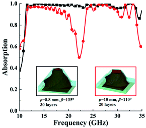 | ||
| Fig. 6 The different type of absorption manipulated by setting different structural parameters of the TPA. | ||
Experimental verification
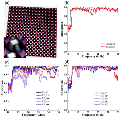
To verify the proposed design strategy, a new approach that enables 3D printing of two different materials (silver ink and resin) simultaneously, was introduced to fabricate the proposed twisted pyramid structure. A sample composed of 15 × 15 unit cells, was printed using a Dragonfly 2020 3D printer (Nano Dimension, Israel) via the multi-material hybrid micro-droplet jetting modeling (MHMJM) technology (see ESI† for detail). Fig. 7(a) shows the details of the fabricated sample, while the measured absorption under normal incidence is illustrated in Fig. 7(b). The measured absorption spectrum shows a good agreement with the simulation results, which convinces that the twisted pyramid design is efficient in enhancing the absorption bandwidth. Moreover, the absorption spectra of the sample at different incident angles for both the TE and TM polarizations were measured. For the TE polarization, the TPA sample maintains high absorption at an incident angle up to 45°, as shown in Fig. 7(c). Furthermore, for the TM polarization, the broadband absorption can be achieved even with the incident angle reaching up to 60°, as shown in Fig. 7(d). Hence, the proposed design also simultaneously realizes polarization insensitivity and wide-incident-angle stability. Moreover, it is possible to extend the twisted metamaterial to the terahertz and infrared frequencies, although a more precise manufacturing process would be required to fabricate such a structure at higher frequencies.Conclusions
This study demonstrates that the absorption bandwidth can be further enhanced by introducing a twisting rotation of each metallic patch of the conversional pyramid wideband metamaterial absorber. Based on the architecture, wideband absorption with absorptivity above 80% from 11.3 to 35.0 GHz is achieved in simulation. The magnetic field distribution analysis shows that the proposed TPA can not only retain the fundamental magnetic resonance but also excite the third-order resonances at lower frequencies, which is responsible for the extra absorption band. The polarization-insensitive absorption shows a strong dependence on the patch rotation angle, and can be enhanced by increasing the metallic layers. To fabricate such a structure, 3D printing with the MHMJM technology was adopted. The measured absorption spectrum agrees well with the simulations. The strategy proposed in this study paves a new way of broadening the absorption bandwidth of metamaterials.Conflicts of interest
There are no conflicts to declare.Acknowledgements
This work was supported by the National Natural Science Foundation of China (No. 61871171, 51803010) and the National Key Research and Development Program of China (No. 2018YFB11067005).References
- D. R. Smith, W. J. Padilla, D. C. Vier, S. C. Nemat-Nasser and S. Schultz, Phys. Rev. Lett., 2000, 84, 4184 CrossRef CAS PubMed.
- N. I. Landy, S. Sajuyigbe, J. J. Mock, D. R. Smith and W. J. Padilla, Phys. Rev. Lett., 2008, 100, 207402 CrossRef CAS PubMed.
- Y. Li, B. An, S. Jiang, J. Gao, Y. Chen and S. Pan, Opt. Express, 2015, 23, 17607 CrossRef CAS PubMed.
- A. Tittl, A. U. Michel, M. Schaferling, X. Yin, B. Gholipour, L. Cui, M. Wuttig, T. Taubner, F. Neubrech and H. Giessen, Adv. Mater., 2015, 27, 4597 CrossRef CAS PubMed.
- X. Q. Jia, Q. Chen, Q. An, Y. J. Zheng and Y. Q. Fu, AIP Adv., 2020, 10, 055018 CrossRef.
- C. M. Watts, X. Liu and W. J. Padilla, Adv. Mater., 2012, 24, OP98 CAS.
- P. Yu, L. V. Besteiro, Y. Huang, J. Wu, L. Fu, H. H. Tan, C. Jagadish, G. P. Wiederrecht, A. O. Govorov and Z. Wang, Adv. Opt. Mater., 2019, 7, 1800995 CrossRef.
- Q. Liang, T. Wang, Z. Lu, Q. Sun, Y. Fu and W. Yu, Adv. Opt. Mater., 2013, 1, 43 CrossRef.
- S. Hu, H. Yang, X. Huang and D. Liu, Appl. Phys. A: Mater. Sci. Process., 2014, 117, 1375 CrossRef CAS.
- T. S. Almoneef and O. M. Ramahi, Appl. Phys. Lett., 2015, 106, 153902 CrossRef.
- D. Lim, D. Lee and S. Lim, Sci. Rep., 2016, 6, 39686 CrossRef CAS PubMed.
- H. Chen, B. I. Wu, B. Zhang and J. A. Kong, Phys. Rev. Lett., 2007, 99, 063903 CrossRef PubMed.
- C. Wang, M. Chen, H. Lei, K. Yao, H. Li, W. Wen and D. Fang, Composites, Part B, 2017, 123, 19 CrossRef CAS.
- J. Zhang, X. Wei, M. Premaratne and W. Zhu, Photonics Res., 2019, 7, 868 CrossRef CAS.
- Y. Z. Cheng, H. Luo and F. Chen, J. Appl. Phys., 2020, 127, 214902 CrossRef CAS.
- H. Luo, Y. Z. Cheng and R. Z. Gong, Eur. Phys. J. B, 2011, 81, 387 CrossRef CAS.
- L. L. Cong, X. Y. Cao, T. Song, J. Gao and J. X. Lan, Sci. Rep., 2018, 8, 9627 CrossRef PubMed.
- L. Stephen, N. Yogesh and V. Subramanian, Sci. Rep., 2019, 9, 10058 CrossRef PubMed.
- Z. Wei, Y. Cao, Y. Fan, X. Yu and H. Li, Opt. Express, 2011, 19, 21425 CrossRef CAS PubMed.
- D. Wen, H. Yang, Q. Ye, M. Li, L. Guo and J. Zhang, Phys. Scr., 2013, 88, 015402 CrossRef CAS.
- X. He, S. Yan, Q. Ma, Q. Zhang, P. Jia, F. Wu and J. Jiang, Opt. Commun., 2015, 340, 44 CrossRef CAS.
- J. Fan, D. Xiao, Q. Wang, Q. Liu and Z. Ouyang, Appl. Opt., 2017, 56, 4388 CrossRef CAS PubMed.
- S. Ji, C. Jiang, J. Zhao, J. Wang and H. Dai, Phys. Status Solidi B, 2019, 256, 1900069 CrossRef CAS.
- F. Ding, Y. Cui, X. Ge, Y. Jin and S. He, Appl. Phys. Lett., 2012, 100, 103506 CrossRef.
- M. Mo, Q. Wen, Z. Chen, Q. Yang, S. Li, Y. Jing and H. Zhang, Acta Phys. Sin., 2013, 62, 237801 Search PubMed.
- Y. J. Kim, Y. J. Yoo, K. W. Kim, J. Y. Rhee, Y. H. Kim and Y. Lee, Opt. Express, 2015, 23, 3861 CrossRef CAS PubMed.
- C. Xu, S. Qu, J. Wang, M. Yan, Y. Pang, W. Wang and H. Ma, J. Adv. Dielectr., 2017, 7, 1750016 CrossRef CAS.
- Y. Cao, V. Fatemi, S. Fang, K. Watanabe, T. Taniguchi, E. Kaxiras and P. Jarillo-Herrero, Nature, 2018, 556, 43 CrossRef CAS PubMed.
- G. Hu, Q. Ou, G. Si, Y. Wu, J. Wu, Z. Dai, A. Krasnok, Y. Mazor, Q. Zhang, Q. Bao, C. Qiu and A. Alu, Nature, 2020, 582, 209 CrossRef CAS PubMed.
- Z. Dai, G. Hu, Q. Ou, L. Zhang, F. Xia, F. J. Garcia-Vidal, C. Qiu and Q. Bao, Chem. Rev., 2020, 120, 6197–6246 CrossRef CAS PubMed.
- G. Hu, A. Krasnok, Y. Mazor, C. Qiu and A. Alu, Nano Lett., 2020, 20, 3217–3224 CrossRef CAS PubMed.
- G. Hu, C. Zheng, J. Ni, C. Qiu and A. Alu, Appl. Phys. Lett., 2021, 118, 211101 CrossRef CAS.
- Z. Dai, G. Hu, G. Si, Q. Ou, Q. Zhang, S. Balendhran, F. Rahman, B. Y. Zhang, J. Z. Ou, G. Li, A. Alu, C. Qiu and Q. Bao, Nat. Commun., 2020, 11, 6086 CrossRef CAS PubMed.
- X. Zhang, X. Xiao, Z. Dai, W. Wu, X. Zhang, L. Fu and C. Jiang, Nanoscale, 2017, 9, 3114–3120 RSC.
- C. Long, S. Yin, W. Wang, W. Li, J. Zhu and J. Guan, Sci. Rep., 2016, 6, 21431 CrossRef CAS PubMed.
- Y. Liu, W. Guo and T. Han, Prog. Electromagn. Res., 2017, 78, 217 CrossRef.
Footnote |
| † Electronic supplementary information (ESI) available. See DOI: 10.1039/d1na00372k |
| This journal is © The Royal Society of Chemistry 2021 |

