
 Open Access Article
 This Open Access Article is licensed under a Creative Commons Attribution-Non Commercial 3.0 Unported Licence
Porous hydrogen-bonded organic framework membranes for high-performance molecular separation†
Xiao-Tian
Jiang
ab,
Qi
Yin
a,
Bai-Tong
Liu
a,
Jun-Yu
Chen
a,
Rui
Wang
a and
Tian-Fu
Liu
 *ab
*ab
aState Key Laboratory of Structural Chemistry, Fujian Institute of Research on the Structure of Matter, Chinese Academy of Sciences, Fujian, Fuzhou 350002, China. E-mail: tfliu@fjirsm.ac.cn
bUniversity of the Chinese Academy of Sciences, Beijing 100049, China
First published on 10th May 2021
Abstract
Hydrogen-bonded organic frameworks (HOFs) with intrinsic, tunable, and uniform pores are promising candidates to act as membranes for molecular separation, but they are yet to be explored in this field. Herein, a type of HOF membrane based on a thin-film nanocomposite (TFN) membrane containing porous HOF (PFC-1) nanoparticles was successfully fabricated via a facile interfacial polymerization method. The homogeneously distributed HOF nanoparticles can provide direct channels in the polyamide (PA) active layer for molecule separation. Due to the ultrathin nature of the TFN membrane and the highly ordered porous structure of the PFC-1 nanoparticles, these flexible HOF membranes exhibit both ultrahigh water permeability (∼546.09 L m−2 h−1 bar−1) and the excellent rejection of dye molecules (e.g., rhodamine B rejection of >97.0%). Furthermore, long-term operational stability (>50 min) and satisfactory cycling performance (>5 cycles) have also been achieved. This study may shed light on the fabrication of HOF membranes for liquid-phase molecular separation.
The global challenges of water pollution and high energy usage are increasingly supporting the exploitation of membrane-based nanotechnology for water purification and wastewater recycling. The established superiority of membrane separation over conventional separation technology lies in its high separation efficiency, low energy requirements, simple operation, high water recovery rates, and environmental friendliness.1 Based on a size-exclusion and pressure-driven separation process, nanofiltration (NF) is deemed a promising form of water-purifying nanotechnology, and it has been widely used in water treatment to efficiently reject organic molecules and multivalent ions.2,3
As a burgeoning membrane fabrication technology, interfacial polymerization has been widely used to fabricate polyamide thin-film composite (TFC) membranes for nanofiltration for water treatment.4 TFC membranes are composed of a porous substrate and an ultrathin nanoporous polyamide (PA) active layer formed via an interfacial polymerization (IP) reaction involving monomers.5 In previous studies on NF membranes, various functional nanomaterials (e.g., titanium dioxide, silica particles, carbon nanotubes, graphene oxide, zeolites, metal–organic frameworks (MOFs), etc.)6–12 were incorporated into the PA active layer to tailor the surface physicochemical properties of the NF membrane (referred to as a thin-film nanocomposite membrane (TFN)) to meet specific water-treatment requirements.13,14 In particular, porous nanoparticles can provide efficient transport channels in the dense PA layer which can allow fast molecular transportation and optimize the balance between permeability and rejection. However, some inorganic materials were found to agglomerate in polymeric matrices due to poor compatibility, presenting great challenges for preparing hybrid TFN membranes. Moreover, it is also inevitable that nonselective voids formed in traditional TFN membranes might result in long-term stability issues, especially under high operation pressures. With better affinity for the organic matrix, porous organic framework materials have become a class of outstanding nanofillers for constructing efficient and stable TFN membranes.15–18
Self-assembled from organic building blocks through hydrogen bonds and intermolecular interactions, hydrogen-bonded organic frameworks (HOFs)19–21 have attracted considerable research attention recently due to their characteristics of high porosity, large surface areas, predictable structures, tunable pore shapes/sizes, solution processability, and easy regeneration.22–25 These unique features make HOFs well-suited for TFN membrane fabrication, and the prepared membranes are low-cost and have reclaimable potential. In previous studies, some HOF membranes have been prepared for gas separation, etc.26–29 However, maintaining both high porosity and mechanical stability in the case of HOF membranes is still a challenge, and HOF membranes are yet to be applied in the field of liquid purification and separation until now. Differing from other inorganic porous nanoparticles, such as zeolites, MOFs, and COFs, HOFs may ameliorate the issues of interfacial defects and poor compatibility within the polymer matrix. In addition, the unique merits of HOFs greatly facilitate the fabrication process and allow for improvements in the separation performance at the atomic level. Therefore, introducing HOFs may provide a novel strategy for constructing robust and high-performance TFN membranes. Learning lessons from previous HOF studies, PFC-1 is chosen as a nanofiller due to its excellent thermal and chemical stabilities and the mild synthetic conditions needed.30 In this study, we report the first example of HOF membranes based on TFN technology. HOF nanoparticles are homogeneously dispersed on a polyethersulfone (PES) substrate and form a continuous membrane with the assistance of the PA active layer. The obtained TFN-based HOF membranes (HOF-TFN) exhibit both ultrahigh water permeability and the excellent rejection of dye molecules with long-term operational stability and satisfactory recycling performance, demonstrating promising application potential for molecular separation in liquids.
The crystalline PFC-1 nanoparticles (denoted as Nano-PFC-1) were successfully synthesized via the self-assembly of 1,3,6,8-tetrakis(p-benzoic acid)pyrene (H4TBAPy) in a mixed solvent of DMF and H2O at room temperature (Fig. 1a, more details in the ESI†). The addition of H2O can increase the nucleation rate of PFC-1, leading to the formation of the desired Nano-PFC-1 particles. The powder X-ray diffraction (PXRD) pattern reveals the high crystallinity and pure phase of Nano-PFC-1 (Fig. 1c). Scanning electron microscopy (SEM) imaging demonstrates that the particle size of Nano-PFC-1 is about 100 nm × 300 nm (Fig. 1b). Since the water stability of the HOF is an essential factor for HOF membranes used under aqueous conditions, Nano-PFC-1 was exposed to water for 10 days to verify the long-term stability. As shown in Fig. 1c, after being exposed to water for 10 days, the XRD pattern of Nano-PFC-1 remains almost identical to the simulated one, demonstrating the high water-stability of Nano-PFC-1 and its suitability for TFN membrane fabrication for water treatment.
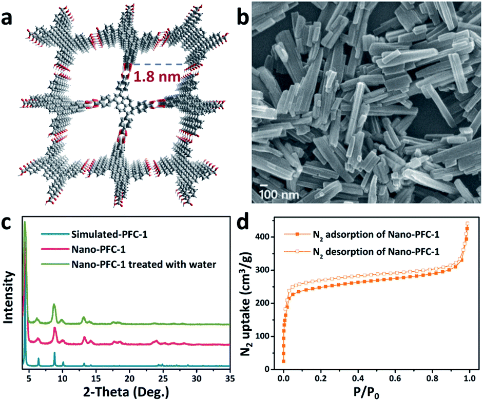 | ||
| Fig. 1 (a) The two-dimensional porous structure of PFC-1. (b) A scanning electron microscopy (SEM) image, (c) powder XRD patterns, and (d) the N2 adsorption/desorption isotherm (77 K) of Nano-PFC-1. | ||
As shown in Scheme 1, Nano-PFC-1 was homogeneously dispersed in an aqueous solution of piperazine (PIP) monomers. Then the mixture was evenly poured onto the surface of a PES substrate and left to stand for 15 min. After removing and evaporating excess solution under atmospheric conditions, the PA/Nano-PFC-1 active layer was formed via an interfacial polymerization method with 1,3,5-benzenetricarbonyl trichloride (TMC), enabling the entrapment of Nano-PFC-1.31,32 By using the same method, HOF membranes containing different amounts of Nano-PFC-1 (0.1, 0.2, and 0.4 mg mL−1) were successfully fabricated and these were named HOF-TFN-1, HOF-TFN-2, and HOF-TFN-4, respectively (Fig. S10†).
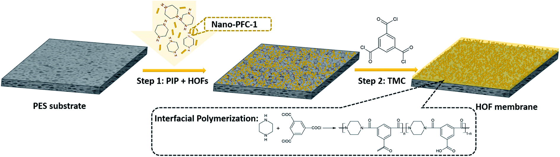 | ||
| Scheme 1 The preparation process of a HOF-TFN membrane containing PFC-1 nanoparticles via interfacial polymerization. | ||
The homogeneous dispersion of nanoparticles is a key factor determining the uniformity of the obtained HOF-TFN membrane. As shown in Fig. S9,† PIP solution containing Nano-PFC-1 shows an obvious Tyndall effect when irradiated by a laser beam, demonstrating that the nanoparticles are homogeneously dispersed in solution. The good dispersion of Nano-PFC-1 in aqueous solution can be attributed to the unbonded polar groups (–COOH) residing on the surfaces of the nanoparticles which are suitably compatible with polar solvents, such as H2O, based on the idea of “like dissolves like”. On the other hand, the partially deprotonated carboxyl groups result in the negatively charged nature of the nanoparticles, with a zeta potential of −39.58 mV (Fig. S7†). Generally, the surface charge significantly influences the dispersity of the nanoparticles and prevents aggregation due to electrostatic repulsion between nanoparticles.33 As a result, hydrophilic Nano-PFC-1 is uniformly dispersed into aqueous PIP solution and firmly bonds with the PA layer after reacting with TMC through an interfacial polymerization reaction. A membrane without the addition of Nano-PFC-1 as a nanoporous filler was also fabricated through the same method (named TFC), as a control experiment. These membranes were characterized based on Fourier-transform infrared-diffuse reflectance spectroscopy (FTIR-DRIFTS) (Fig. S6†). Compared with TFC, the HOF-TFN-2 membrane shows an obvious absorption peak at 1708 cm−1, which can be ascribed to the –COOH stretching vibrations of Nano-PFC-1. The PXRD patterns reveal that the crystal structure of the HOF membrane undergoes no changes during filtration tests (Fig. S8†).31 The surface morphologies of the PES substrate, TFC, and HOF-TFN membrane are revealed via both top-view and cross-sectional SEM images (Fig. 2a–f, S1 and S2†). Compared with TFC, the surface morphology of HOF-TFN is obviously changed. The addition of Nano-PFC-1 makes the surface morphology much rougher, which may improve the surface area of the membrane (Fig. S5†) and enhance the water flux. Additionally, upon increasing the amount of Nano-PFC-1, the membranes show a denser and more uniform topography (Fig. S1†). This is probably because the introduction of Nano-PFC-1 can provide more active sites and therefore anchor more PIP monomers to the substrate surface. The existence of more initial polyamide nuclei then causes even polymerization, resulting in a more compact membrane. As shown in the cross-section images in Fig. 2 and S1,† every HOF-TFN membrane contains a porous PES substrate tightly covered with a dense polyamide PA layer. The thickness of the polyamide/Nano-PFC-1 layer was about 7 μm (Fig. S2†).
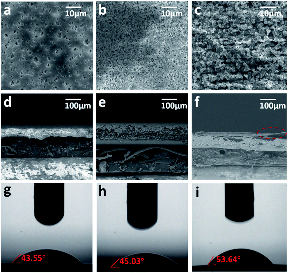 | ||
| Fig. 2 SEM images showing (a–c) top-down and (d–f) cross-sectional views of (a and d) the PES substrate, (b and e) TFC, and (c and f) HOF-TFN-2. Water-in-air contact angles for PES (g), TFC (h), and HOF-TFN-2 (i). | ||
The surface hydrophilicity is another considerable factor relating to nanofiltration membranes and it is highly connected to the water permeability.34 As shown in Fig. 2g–i and S2 and S3,†, compared with the TFC membrane, the contact angle slightly increases for HOF-TFN due to the incorporation of Nano-PFC-1. The transient water contact angle of the TFC membrane is 45.03°. Upon increasing the amount of Nano-PFC-1, the contact angle increases to 49.93° ± 0.5° for HOF-TFN-1, 53.64° ± 0.5° for HOF-TFN-2, and 61.7 ± 0.5° for HOF-TFN-4 (Table S1†). This result further demonstrates that the incorporation of Nano-PFC-1 does not greatly change the hydrophilicity of the membrane.
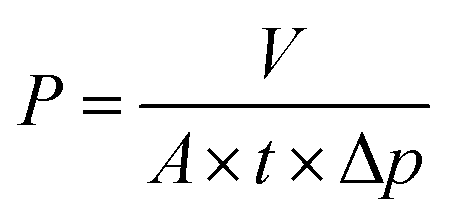
To explore the capacity for liquid separation, the water permeance of the HOF-TFN membranes was first evaluated. The permeance (P) values, in L m−2 h−1 bar−1, were calculated using the following equation:
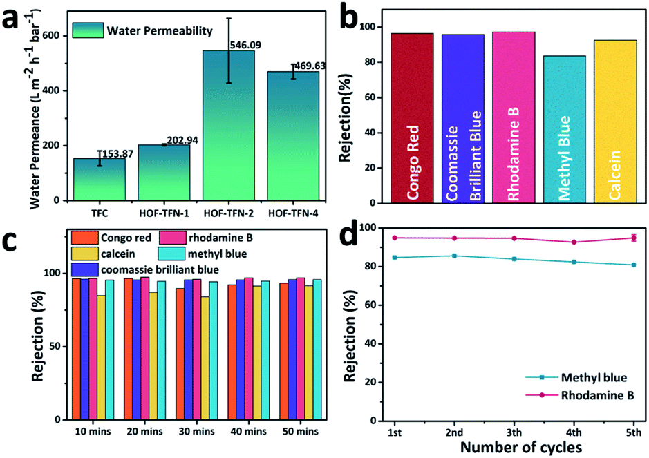 | ||
| Fig. 3 (a) The water permeance values of the TFC, HOF-TFN-1, HOF-TFN-2, and HOF-TFN-4 membranes. (b) The different dye rejection rates of HOF-TFN-2 in a short time (about 5 min). (c) The dye separation performances of the HOF-TFN-2 membrane during 50 min of testing. (d) The consistent dye rejection performance of the HOF-TFN-2 membrane over 5 reuse cycles. | ||
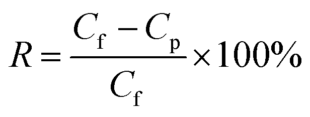
To further explore the nanofiltration performance of HOF-TFN membranes for removing divalent salts and hazardous organic dye molecules from industrial wastewater, we conducted experiments to evaluate the separation abilities toward Na2SO4 and five toxic dyes with different molecular weights and sizes (methyl blue (MB), 799 g mol−1, skin irritant; rhodamine B (RB), 479 g mol−1, damaging to the eyes and throat; Congo red (CR), 686 g mol−1, carcinogen and mutagen; calcein (CC), 623 g mol−1, respiratory tract irritant; and Coomassie brilliant blue (CB), 826 g mol−1, epidermal cell irritant; Fig. S12†). Herein, the SO42− concentration was measured via ion chromatography. The dye concentrations in the feed and permeate filtered through the HOF-TFN membranes were calculated based on UV-vis spectroscopy absorbance (Fig. 4 and S14–S16†). The rejection rate (R, %) values for the solutions were determined using the following equation:
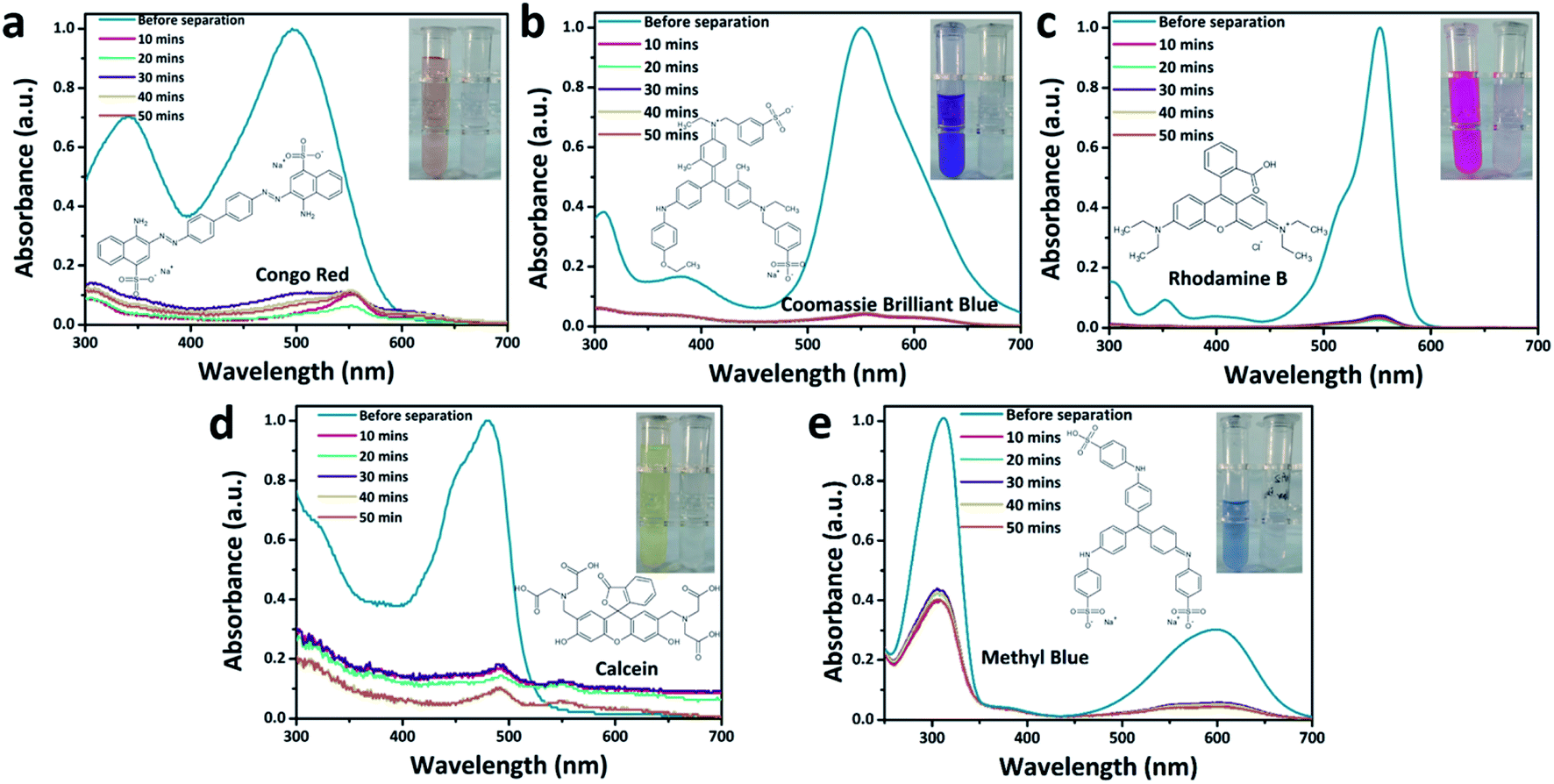 | ||
| Fig. 4 The chemical structures of the dyes, digital photos, and UV-vis spectra of the feed (blue lines) and permeate (lines in other colors) solutions: (a) Congo red, (b) Coomassie brilliant blue, (c) rhodamine B, (d) calcein, and (e) methyl blue. | ||
Furthermore, the separation stability of the HOF-TFN-2 membrane was evaluated based on long-term continuous experiments. As shown in Fig. 4 and S15,† the absorbance peak of the dye in solution significantly decreases after filtration, showing the excellent dye separation abilities. During the filtration process, there are only slightly decreases in dye retention (Fig. 3c and S15c†), confirming the reliable retention efficiency of the HOF-TFN-2 membrane for at least 50 minutes and even 300 minutes.
Finally, the cycling durability of the HOF-TFN-2 membrane was also evaluated based on a 5-cycle nanofiltration test involving methyl blue and rhodamine B rejection, separately. Each cycle consists of dye solution filtration through the HOF-TFN-2 membrane for 1 h followed by H2O filtration for 30 min. As shown in Fig. 3d and S16,† even after 5 cycles of operation, the HOF-TFN-2 membrane shows consistent dye rejection performance, thus confirming the desired long-term retention durability and mechanical pore robustness. To sum up, the obtained HOF-TFN-2 membrane with high dye retention and water permeation flux is an excellent candidate for wastewater treatment.
Conclusions
In summary, we exploited a facile interfacial polymerization strategy to fabricate TFN-based HOF membranes using a PA/Nano-PFC-1 active layer on a PES substrate. This strategy is proved to load HOF nanoparticles at a controlled concentration and with an even distribution on the active layer, and the fabrication of the HOF membranes can be completed in a short time. Due to the ultrathin active layer and the uniform pore structure of the HOF, the prepared membranes exhibited ultrahigh water-permeability (∼546.09 L m−2 h−1 bar−1) and the excellent rejection of organic dye molecules. Accordingly, the membranes exhibited long-term operational stability and satisfactory recyclability. We think that this cost-effective IP strategy opens up a new pathway for the design and fabrication of HOF membranes and it can expand the application field of HOF materials.Conflicts of interest
The authors declare no conflicts of interest.Acknowledgements
We gratefully acknowledge the National Key Research and Development Program of China (Grant No. 2018YFA0208600), CAS-Iranian Vice presidency for Science and Technology Joint Research Project (Grant No. 121835KYSB20200034), National Natural Science Foundation of China (Grant No. 21871267, 22071246, 22005305), and China Postdoctoral Science Foundation (Grant No. 2020M671955).Notes and references
- R. Zhang, Y. Liu, M. He, Y. Su, X. Zhao, M. Elimelech and Z. Jiang, Chem. Soc. Rev., 2016, 45, 5888–5924 RSC.
- M. R. Esfahani, S. A. Aktij, Z. Dabaghian, M. D. Firouzjaei, A. Rahimpour, J. Eke, I. C. Escobar, M. Abolhassani, L. F. Greenlee and A. R. Esfahani, Sep. Purif. Technol., 2019, 213, 465–499 CrossRef CAS.
- A. W. Mohammad, Y. Teow, W. Ang, Y. Chung, D. Oatley-Radcliffe and N. Hilal, Desalination, 2015, 356, 226–254 CrossRef CAS.
- M. B. M. Y. Ang, J. M. Pereira, C. A. Trilles, R. R. Aquino, S.-H. Huang, K.-R. Lee and J. Y. Lai, Sep. Purif. Technol., 2019, 210, 521–529 CrossRef CAS.
- F. Zhang, J. B. Fan and S. Wang, Angew. Chem., Int. Ed., 2020, 59, 21840–21856 CrossRef CAS PubMed.
- J. Wang, Y. Wang, J. Zhu, Y. Zhang, J. Liu and B. Van der Bruggen, J. Membr. Sci., 2017, 533, 279–288 CrossRef CAS.
- Y. L. Li, I. A. Kinloch and A. H. Windle, Science, 2004, 304, 276–278 CrossRef CAS PubMed.
- C. S. Rodolfo, I. Kazuo, M. Jun, S. Shigeru, M. G. Aaron, A. Celia, T. Yoshihiro, A. Yamanaka, S. Tejiima and K. Fujisawa, Nanoscale, 2020, 12, 19628–19637 RSC.
- S. Zinadini, A. A. Zinatizadeh, M. Rahimi, V. Vatanpour and H. Zangeneh, J. Membr. Sci., 2014, 453, 292–301 CrossRef CAS.
- L. Yang, Z. Wang and J. Zhang, J. Membr. Sci., 2017, 532, 76–86 CrossRef CAS.
- Z. Hu, Y. Wang and D. Zhao, Chem. Soc. Rev., 2021, 50, 4629–4683 RSC.
- J. Hou, P. D. Sutrisna, Y. Zhang and V. Chen, Angew. Chem., Int. Ed., 2016, 55, 3947–3951 CrossRef CAS PubMed.
- J. R. Werber, C. O. Osuji and M. Elimelech, Nat. Rev. Mater., 2016, 1, 1–15 Search PubMed.
- N. A. Khan, R. Zhang, H. Wu, J. Shen, J. Yuan, C. Fan, L. Cao, M. A. Olson and Z. Jiang, J. Am. Chem. Soc., 2020, 142, 13450–13458 CrossRef PubMed.
- S. Sorribas, P. Gorgojo, C. Téllez, J. Coronas and A. G. Livingston, J. Am. Chem. Soc., 2013, 135, 15201–15208 CrossRef CAS PubMed.
- J. Guo, Y. Zhang, Y. Zhu, C. Long, M. Zhao, M. He, X. Zhang, J. Lv, B. Han and Z. Tang, Angew. Chem., Int. Ed., 2018, 57, 6873–6877 CrossRef CAS PubMed.
- Z. Wang, S. Zhang, Y. Chen, Z. Zhang and S. Ma, Chem. Soc. Rev., 2020, 49, 708–735 RSC.
- J. Campbell, R. Davies, D. C. Braddock and A. Livingston, J. Mater. Chem. A, 2015, 3, 9668–9674 RSC.
- T. Li, B. T. Liu, Z. B. Fang, Q. Yin and T. F. Liu, J. Mater. Chem. A, 2021, 9, 4687–4691 RSC.
- A. Karmakar, R. Illathvalappil, B. Anothumakkool, A. Sen, P. Samanta, A. V. Desai, S. Kurungot and S. K. Ghosh, Angew. Chem., Int. Ed., 2016, 55, 10667–10671 CrossRef CAS PubMed.
- J. Lü and R. Cao, Angew. Chem., Int. Ed., 2016, 55, 9474–9480 CrossRef PubMed.
- Z. B. Han, Z. Z. Xiao, M. Hao, D. Q. Yuan, L. Liu, N. Wei, H. M. Yao and M. Zhou, Cryst. Growth Des., 2015, 15, 531–533 CrossRef CAS.
- Y. He, S. Xiang and B. Chen, J. Am. Chem. Soc., 2011, 133, 14570–14573 CrossRef CAS PubMed.
- F. Hu, C. Liu, M. Wu, J. Pang, F. Jiang, D. Yuan and M. Hong, Angew. Chem., Int. Ed., 2017, 56, 2101–2104 CrossRef CAS PubMed.
- R. B. Lin, Y. He, P. Li, H. Wang, W. Zhou and B. Chen, Chem. Soc. Rev., 2019, 48, 1362–1389 RSC.
- J. F. Feng, T. F. Liu and R. Cao, Angew. Chem., Int. Ed., 2020, 59, 22392–22396 CrossRef CAS.
- K. Ma, P. Li, J. H. Xin, Y. Chen, Z. Chen, S. Goswami, X. Liu, S. Kato, H. Chen, X. Zhang, J. Bai, M. C. Wasson, R. R. Maldonado, R. Q. Snurr and O. K. Farha, Cell Rep. Phys. Sci., 2020, 1, 100024 CrossRef.
- S. Feng, Y. Shang, Z. Wang, Z. Kang, R. Wang, J. Jiang, L. Fan, W. Fan, Z. Liu, G. Kong, Y. Feng, S. Hu, H. Guo and D. Sun, Angew. Chem., Int. Ed., 2020, 59, 3840–3845 CrossRef CAS PubMed.
- B. T. Liu, X. H. Pan, D. Y. Nie, X. J. Hu, E. P. Liu and T. F. Liu, Adv. Mater., 2020, 32, e2005912 CrossRef PubMed.
- Q. Yin, P. Zhao, R. J. Sa, G. C. Chen, J. Lu, T. F. Liu and R. Cao, Angew. Chem., Int. Ed., 2018, 57, 7691–7696 CrossRef CAS PubMed.
- F. Xiao, X. Hu, Y. Chen and Y. Zhang, ACS Appl. Mater. Interfaces, 2019, 11, 47390–47403 CrossRef CAS PubMed.
- J. Zhu, L. Qin, A. Uliana, J. Hou, J. Wang, Y. Zhang, X. Li, S. Yuan, J. Li, M. Tian, J. Lin and B. Van der Bruggen, ACS Appl. Mater. Interfaces, 2017, 9, 1975–1986 CrossRef CAS PubMed.
- J. Hou, C. Bao, S. Qu, X. Hu, S. Nair and Y. Chen, Appl. Surf. Sci., 2018, 459, 185–193 CrossRef CAS.
- H. Shen, S. Wang, H. Xu, Y. Zhou and C. Gao, J. Membr. Sci., 2018, 565, 145–156 CrossRef CAS.
- J. M. Gohil and P. Ray, Sep. Purif. Technol., 2017, 181, 159–182 CrossRef CAS.
Footnote |
| † Electronic supplementary information (ESI) available. See DOI: 10.1039/d1na00199j |
| This journal is © The Royal Society of Chemistry 2021 |