 Open Access Article
Creative Commons Attribution 3.0 Unported Licence
Carbon-coated Fe3O4 core–shell super-paramagnetic nanoparticle-based ferrofluid for heat transfer applications†
Mohd
Imran
 a,
Nasser
Zouli
 a,
Tansir
Ahamad
 b,
Saad M.
Alshehri
b,
Mohammed Rehaan
Chandan
b,
Saad M.
Alshehri
b,
Mohammed Rehaan
Chandan
 *c,
Shahir
Hussain
 d,
Abdul
Aziz
 e,
Mushtaq Ahmad
Dar
 f and
Afzal
Khan
 *g
*g
aDepartment of Chemical Engineering, Faculty of Engineering, Jazan University, P.O. Box. 706, Jazan 45142, Saudi Arabia
bDepartment of Chemistry, College of Science, King Saud University, P.O. Box 2455, Riyadh 11451, Saudi Arabia
cColloids and Polymers Research Group, School of Chemical Engineering, Vellore Institute of Technology, Vellore, Tamilnadu 632014, India. E-mail: chandan1816@gmail.com; Tel: +91-04162202668
dDepartment of Electrical Engineering, Faculty of Engineering, Jazan University, P.O. Box. 706, Jazan 45142, Saudi Arabia
eDepartment of Mechanical Engineering, Faculty of Engineering, Jazan University, P.O. Box. 706, Jazan 45142, Saudi Arabia
fCenter of Excellence for Research in Engineering Materials, College of Engineering, King Saud University, Riyadh, 11421, Kingdom of Saudi Arabia
gState Key Laboratory of Silicon Materials, School of Materials Science and Engineering, Zhejiang University, Hangzhou 310027, China. E-mail: afzalkhan@zju.edu.cn; Tel: +86-15669097732
First published on 8th February 2021
Abstract
Herein, we report the investigation of the electrical and thermal conductivity of Fe3O4 and Fe3O4@carbon (Fe3O4@C) core–shell nanoparticle (NP)-based ferrofluids. Different sized Fe3O4 NPs were synthesized via a chemical co-precipitation method followed by carbon coating as a shell over the Fe3O4 NPs via the hydrothermal technique. The average particle size of Fe3O4 NPs and Fe3O4@C core–shell NPs was found to be in the range of ∼5–25 nm and ∼7–28 nm, respectively. The thickness of the carbon shell over the Fe3O4 NPs was found to be in the range of ∼1–3 nm. The magnetic characterization revealed that the as-synthesized small average-sized Fe3O4 NPs (ca. 5 nm) and Fe3O4@C core–shell NPs (ca. 7 nm) were superparamagnetic in nature. The electrical and thermal conductivities of Fe3O4 NPs and Fe3O4@C core–shell NP-based ferrofluids were measured using different concentrations of NPs and with different sized NPs. Exceptional results were obtained, where the electrical conductivity was enhanced up to ∼3222% and ∼2015% for Fe3O4 (ca. 5 nm) and Fe3O4@C core–shell (ca. 7 nm) NP-based ferrofluids compared to the base fluid, respectively. Similarly, an enhancement in the thermal conductivity of ∼153% and ∼116% was recorded for Fe3O4 (ca. 5 nm) and Fe3O4@C core–shell (ca. 7 nm) NPs, respectively. The exceptional enhancement in the thermal conductivity of the bare Fe3O4 NP-based ferrofluid compared to that of the Fe3O4@C core–shell NP-based ferrofluid was due to the more pronounced effect of the chain-like network formation/clustering of bare Fe3O4 NPs in the base fluid. Finally, the experimental thermal conductivity results were compared and validated against the Maxwell effective model. These results were found to be better than results reported till date using either the same or different material systems.
1. Introduction
The dispersion of nanoparticles (NPs) in various fluids enhances their thermal conductivity, which have potential application in heat transfer as coolants in various systems such as automobile radiators, refrigerators, process engineering systems, electronic devices, solar energy heaters, pulsating pipes, and thermosyphons.1–5 There are several typical base fluids used for heat transfer applications such as water, ethylene glycol, ethanol, methanol, dimethyl formamide, polyalfaolefin, and oils.6–13 Ferrofluids or magnetic fluids are stable colloidal homogeneous suspensions of magnetic NPs (∼10 nm in diameter) in an aqueous or a non-aqueous carrier liquid.14 The dispersion of NPs in these base fluids results in the formation of a nanofluid, and if NPs are magnetic in nature, the resulting fluid is termed a ferrofluid. Generally, NPs show enhanced electrical, thermal, optical and mechanical properties because of their large surface to volume ratio.15–17 Magnetic NPs such as Fe3O4 have attracted great interest from the scientific community because of their unique properties such as biocompatibility, high electrochemical response and thermal stability.18 Consequently, Fe3O4 NP-based ferrofluids exhibit enhanced thermal and electrical conductivities.19–21 However, NPs have high surface energy, which results in their agglomeration or settling at the bottom of the dispersion liquid when used for a long period. Therefore, the coating of inorganic or organic materials over Fe3O4 NPs is necessary for their good dispersion and long-term stability.18 The oxidation of magnetite (Fe3O4) NPs leads to the formation of a stable phase of iron oxide, which is γ-Fe2O3 NPs (maghemite), and a more stable form, i.e., α-Fe2O3 (hematite) under particular conditions.22 Therefore, it is necessary to protect superparamagnetic Fe3O4 NPs from physical and chemical changes by encapsulating them with other materials. Accordingly, capping Fe3O4 NPs with another sub-material (shell) can result in their good dispersion and stability, as reported by Sharma et al.18 Hence, various core–shell NPs have been reported thus far, especially Fe3O4@C core–shell NPs, for e.g., Xuan et al. synthesized carbon-encapsulated Fe3O4 core–shell particles via the reduction of glucose.23 Conversely, Wang et al. synthesized single carbon layer-coated ultra-small Fe3O4 NPs using a one-step hydrothermal technique for surface-enhanced Raman spectroscopy studies,24 and He et al. used in situ-synthesized carbon-encapsulated Fe3O4 NPs as an anode material for lithium ion batteries.25 Moreover, Zhao et al. employed the hydrothermal method for the synthesis of interconnected carbon nanospheres covering Fe3O4 NPs.26 Similarly, Liang et al. synthesized Fe3O4@Au core–shell NPs for the ultrasensitive detection of carbohydrate–protein interactions.27 A magnetic metal nanocomposite was coated by carbon to prepare FeNi@C core–shell NPs.28 Li et al. synthesized Cu@C core–shell NPs via a simple state reduction method and investigated their optical properties.29 Similarly, Ag@C core–shell NPs were synthesized via the wet chemical route and catalysed under hydrothermal conditions, which exhibited hydrophilic and unique optical properties.30 Moreover, the reverse micelle method was employed to prepare Fe@Fe-oxide and Fe@Au core–shell nanostructures.31,32 These core–shell NPs possessed an added advantage over other NPs as their shell can protect their core from physical and chemical changes. Thus, bio-incompatible, highly reactive and toxic NPs can be covered with biologically compatible, non-reactive and environmentally friendly materials in the form of shells.To further explore the unique properties of core–shell NPs, they were introduced in a dispersion liquid to make stable ferrofluids for various applications. Recently, ferrofluids were prepared by dispersing Fe3O4 NPs in mineral oil and γ-Fe2O3 NPs in various base fluids.19–21 Their thermal conductivities were enhanced multiple folds compared to that of the base liquids. Similarly, Cui et al. synthesized superparamagnetic Fe3O4 NPs, which were dispersed in perfluoropolyether base fluid, and the resulting ferrofluid exhibited enhanced viscosity and thermal conductivity.33 Zupan et al. prepared a ferrofluid by dispersing iron(II,III) oxide NPs in water for heat transfer application.34 Furthermore, Fe3O4 NPs were dispersed in water and a maximum 200% enhancement in thermal conductivity was observed.35
Core–shell NP-based ferrofluids also exhibit good biocompatibility and improved properties. Accordingly, the other applications of core–shell NP-based ferrofluids include multimodal imaging, hyperthermia, drug delivery, cytocompatibility tumour targeting, cancer chemotherapy and thermotherapy and other possible biological applications.36–38 Similarly, magnetic NP systems are widely used in the MRI-guided delivery of magneto-electric drug nano-carriers to the brain.39 Magneto-electric core–shell NPs exhibit enhanced cell uptake and control drug release under the influence of an applied and magnetic field.40 To manage central nervous system (CNS) diseases, surface-engineered magnetic NPs have been employed as a tool via image-guided therapy and theranostics.41 Magneto-electric NPs (MENPs) are stimulus-responsive nanosystems for controlled drug release and cell uptake.42,43 The futuristic application of these magnetic core–shell nanostructures may be projected in the biomedical field, where previous studies showed the use of magnetic core–shell nanoparticles as an antimicrobial agent.44 Targeted drug delivery and drug delivery to the brain are limited due to their complicated methods and structural behavior. Thus, to achieve this goal, magnetic core–shells have been suggested as important nanocarriers.45,46
Although nanofluids based on non-magnetic NPs are widely studied, to date, few studies investigating the thermal conductivity of magnetic core–shell NPs for heat transfer applications have been performed.47–49 To the best of our knowledge, the electrical and thermal conductivities of superparamagnetic Fe3O4@C core–shell NPs have rarely been reported. Therefore, herein, we synthesized Fe3O4 NPs using a chemical co-precipitation method followed by the hydrothermal synthesis technique, which led to the formation of Fe3O4@C core–shell NPs. Furthermore, these NPs were characterized using various techniques and their electrical and thermal conductivities were measured. The super-paramagnetic Fe3O4@C core–shell NPs exhibited good thermal and electrical properties, and thus can be exploited for heat transfer applications, such as cooling of electronic devices, fuel cells, and solar cells.50
2. Experimental
2.1. Materials and methods
Ferrous sulphate heptahydrate (FeSO4·7H2O), ferric chloride hexahydrate (FeCl3·6H2O) and sodium hydroxide (NaOH) were purchased from Sigma Aldrich. Absolute alcohol and hydrochloric (HCl) acid were procured from Chem-Lab (Belgium) and Scharlau (Spain), respectively. All chemicals were of research grade and used without further purification. Similarly, fructose of analytical grade was purchased from Gem-Chem (India) and used as received. Deionized (DI) water obtained from an ultrapure water unit (Puris-Expe water system) was used during the synthesis of the Fe3O4 NPs.2.2. Synthesis of Fe3O4 NPs
Fe3O4 NPs were synthesized via a chemical co-precipitation method. In a typical co-precipitation method, 0.32 mol of ferrous sulphate heptahydrate (FeSO4·7H2O) and 0.64 mol of ferric chloride were dissolved in 100 mL DI water separately. The Fe2+/Fe3+ ions were mixed properly before dispersing them in an alkali solution. The ion mixture was then transferred to a 100 mL burette. In a 250 mL round-bottom flask, 1.5 M NaOH solution was prepared and the volume was made up to 100 mL. The iron salt ions were then added dropwise to the above alkali solution under vigorous stirring. The pH of the solution was maintained at around 11–12 during the reaction. An additional amount of NaOH solution could be added to the reaction vessel if needed. As soon as the iron salts were added to the alkali solution, precipitation of the salts started, resulting in the formation of a black-colored co-precipitate. The precipitate was then stirred for 30 min at room temperature. Subsequently, the solution was allowed to settle for 30 min and with the help of a strong magnet, the precipitate was separated from the unreacted solution. Finally, the obtained precipitate was washed several times with distilled water. Similarly, by tuning the pouring of aqueous solution of iron salt (drops) into the aqueous solution of alkali and stirring rate, Fe3O4 NPs with three different sizes were obtained including 5 nm, 12 nm and 25 nm.2.3. Synthesis of Fe3O4@C core–shell NPs
The as-synthesized Fe3O4 NPs of different sizes were dispersed separately in a 5 M aqueous solution of glucose and kept in a tight capped 500 mL bottle, which was half-filled with the solution. To coat a carbon shell over the Fe3O4 NPs, the sample solution was shaken properly and then left in an autoclave for 4–5 h at high pressure and 180 °C. The carbonization of glucose occurred at 180 °C during the hydrothermal treatment. After this reaction, the system was allowed to cool to room temperature. A dark black-colored solution smelling like sugarcane vinegar was obtained, which was decanted with the help of a strong magnet. Subsequently, the sample was washed with distilled water several times. Finally, the black-colored precipitate was collected and dried at 80 °C for 4–5 h in an oven.18,23 Consequently, Fe3O4@C core–shell NPs with different sizes including 7 nm, 14 nm and 28 nm were obtained using this technique.2.4. Preparation of ferrofluids
We introduced fine powders of Fe3O4 and Fe3O4@C core–shell NPs into DI water in separate beakers. Given that the NPs were highly magnetic in nature, the mixtures were sonicated for 3–4 hours for better dispersion of the NPs. Eventually, we obtained a highly monodispersed NP solution. The prepared ferrofluids were found to be stable without any external applied magnetic field for a long time. Before their application in a heat exchanger, the ferrofluids were sonicated again for better heat transfer results. Different concentrations of ferrofluids were prepared in a similar way for heat transfer and electrical conductivity measurements.2.5. Characterization
The phase and crystallinity of the as-synthesized Fe3O4 and Fe3O4@C powder samples were identified by XRD (D8 AαS Advance X-ray diffractometer using Cu Kα radiation, λ = 1.54156 Å). Raman analyses were conducted using a Raman spectrometer (Aramis LabRam spectrometer). The microstructure analyses of the as-synthesized powders were carried out using a transmission electron microscope (TEM) (JEOL, JEM2100F) operated at 200 kV. X-ray photoelectron spectroscopy (XPS) was performed for elemental information using an X-ray photoelectron spectrometer (Thermo Fisher, USA). Moreover, the functional groups were identified using FT-IR (ATR-FT-IR Nicolet iS 10). The magnetic properties of the as-synthesized powders were analyzed using an ADE 3473-70 Technologies vibrating sample magnetometer (VSM) in the range of −10 kOe to 10 kOe with a magnetization error of ±1%. The zeta potential values of the prepared ferrofluids were obtained using a Zetasizer (Nano-ZS; Malvern, UK) operated at room temperature. The electrical conductivities of the ferrofluids were measured using an HI 2300 NaCl/TDS/EC meter (HANNA Instruments). For the measurement of the thermal conductivity of the ferrofluids with different concentrations, a WL-373 (GUNT Hamburg, Germany) instrument was used. This unit is particularly suited for the determination of the coefficients of thermal conduction of liquids and gaseous materials. The unit was comprised of a double-walled cylinder with an integrated heater acting as the heat source, and the surrounding cylinder as the heat sink. There was a narrow slot in the unit, which was sufficient to prevent heat by convection, and therefore the heat of transfer in the slot is due to the thermal conduction. Due to the constant width of the slot, thermal conduction occurs in a plane wall. The heat transferred, Q, can be calculated using Fourier's law as follows: | (1) |
3. Results and discussion
Fig. 1a and b show the XRD patterns of the as-synthesized Fe3O4 powder and Fe3O4@C powder samples, respectively. Fig. 1a shows diffraction peaks at 2θ values of around 30.09°, 35.45°, 43.02°, 53.59°, 57.20° and 62.72°, which correspond to the (220), (311), (400), (422), (511) and (440) crystal planes, respectively. The peak positions and relative intensities of the Fe3O4 powder sample matched with the JCPDS card no. 19-629, which confirmed the crystalline nature and cubic spinel structure of the powder sample. Similarly, for the Fe3O4@C powder sample, the diffraction peaks at around 30.2°, 35.5°, 43.17°, 53.59°, 57.37° and 62.72° correspond to the (220), (311), (400), (422), (511) and (440) crystal planes, respectively, as shown in Fig. 1b.18,23 There is a negligible shift in the diffraction peaks, which suggest that the Fe3O4 powder sample did not transform into another iron oxide phase during the synthesis of the Fe3O4@C powder sample.18,23Fig. 1c and d show the FT-IR spectra of the Fe3O4 and Fe3O4@C powder samples, respectively. The peaks observed at 571 and 631 cm−1 correspond to the vibrations of Fe–O (Fig. 1c).18,23,51 However, for the Fe3O4@C powder sample, the Fe–O vibration bands were observed at 575 and 635 cm−1. The small shift in the Fe–O vibration band is due to the carbon coating over Fe3O4. Moreover, the decrease in the vibration frequency of the bond indicates the addition of carbon. The peaks at 2924 cm−1 and 2862 cm−1 refer to the C–H stretching vibrations, and the peaks at 1416 cm−1 and 1066 cm−1 refer to the C–H bending vibrations and C–O stretching vibrations, respectively, for the Fe3O4@C NPs. The broad band observed at 3300–3450 cm−1 and the band at 1611 cm−1 present in both spectra correspond to the O–H stretching mode and the H–O–H bending mode, respectively, indicating the presence of interstitial water molecules.18,23,52 The Raman spectrum of the Fe3O4@C powder sample is shown in Fig. 1e, where the intense D band and G band were observed at around 1352 and 1598 cm−1, respectively. The D band can be attributed to sp2 carbon, which indicates a disordered graphitic structure and the G band can be attributed to sp3 carbon. The other significant peaks at around 396 cm−1 and 487 cm−1 in the Raman spectrum suggest the T2g phonon vibration mode in Fe3O4.53 The peaks at 574 cm−1 and 667 cm−1 suggest the Fe![[double bond, length as m-dash]](https://www.rsc.org/images/entities/char_e001.gif) O vibration, which is known as the A1g phonon vibration mode and generally observed due to the symmetric stretching of the O atom along the Fe–O bonds in Fe3O4.53
O vibration, which is known as the A1g phonon vibration mode and generally observed due to the symmetric stretching of the O atom along the Fe–O bonds in Fe3O4.53
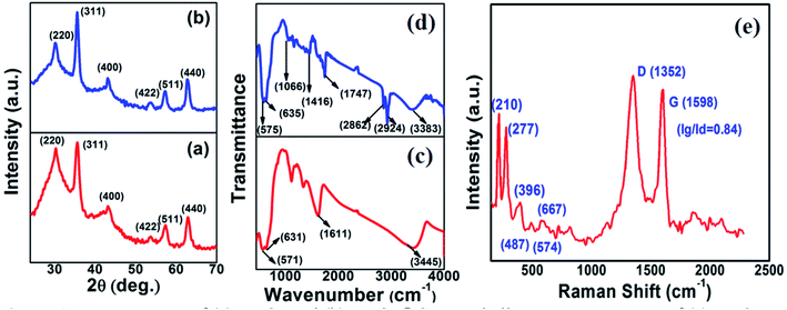 | ||
| Fig. 1 XRD patterns of (a) Fe3O4 and (b) Fe3O4@C core–shell NPs. FTIR spectra of (c) Fe3O4 and (d) Fe3O4@C core–shell NPs and (e) Raman spectrum of Fe3O4@C core–shell NPs. | ||
Fig. 2a and b show the low-magnification TEM images of the as-synthesized Fe3O4 and Fe3O4@C powder samples, and their corresponding size distribution histograms are shown in Fig. 2c and d, respectively. It was observed that the as-synthesized powder samples were comprised of NPs, which were monodispersed on the TEM Cu grid. The average particle size of the Fe3O4 NPs and Fe3O4@C NPs were found to be around 5 nm and 7 nm, respectively. Similarly, the TEM images of two different sized Fe3O4 NPs (12 nm and 25 nm) and Fe3O4@C core–shell NPs (14 nm and 28 nm) together with their corresponding size distribution histograms are shown in Fig. S1 (ESI†). Fig. 3a and b show the high-magnification TEM and HRTEM images of the Fe3O4 NPs, respectively. As shown in Fig. 3b, three different types of planes were identified with the d spacings of 0.29, 0.26 and 0.21 nm, which correspond to the (220), (311) and (400) planes of cubic Fe3O4.53 The HRTEM results also confirmed the crystalline nature of the as-synthesized Fe3O4 NPs and suggest that they did not transform into another stable form of iron oxide. Similarly, Fig. 3c and d show the high-magnification TEM and HRTEM images of the carbon-encapsulated Fe3O4 (Fe3O4@C) NPs, respectively. The carbon-shell coating over the Fe3O4 NPs was found to be amorphous in nature, and the thickness of the carbon shell over a random Fe3O4 core NP was found to be approximately in the range of 0.8–1.2 nm.
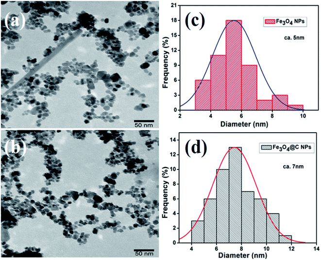 | ||
| Fig. 2 Low magnification TEM images of (a) Fe3O4 NPs (5 nm) and (b) Fe3O4@C core–shell NPs (7 nm) and (c) and (d) their corresponding size distribution histograms, respectively. | ||
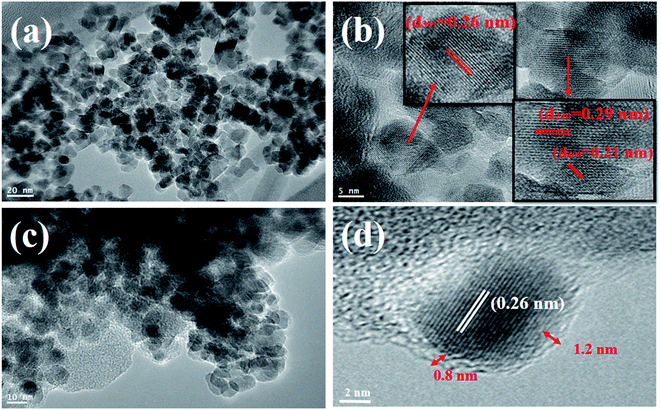 | ||
| Fig. 3 High-magnification TEM images of (a) Fe3O4 NPs and (c) Fe3O4@C core–shell NPs. (b) and (d) HRTEM images of Fe3O4 NPs and a random Fe3O4@C core–shell NP. | ||
Fig. 4a shows the XPS survey scans of the bare Fe3O4 NPs (red color) and Fe3O4@C core–shell NPs (black color). Three significant peaks corresponding to the Fe 2p, O 1s and C 1s core levels were obtained for the carbon-coated Fe3O4 NPs, which confirmed the composition of the Fe3O4@C core–shell NPs, whereas the C 1s core level peak was missing for the bare Fe3O4 NPs. Fig. 4b shows the high-resolution spectrum of Fe 2p core level, i.e., Fe 2p3/2 and Fe 2p1/2, which correspond to the binding energies 710.5 eV and 724.1 eV, respectively. No peak was observed at 719 eV, which corresponds to α-Fe2O3, indicating that no phase transformation occurred.53 Fe exists in two states, i.e., Fe2+ and Fe3+, in Fe3O4. The peak at 710.3 eV (pink) is attributed to the Fe2+ state in Fe 2p3/2. The peak observed at 712.7 eV (purple) corresponds to the Fe3+ state in Fe 2p3/2. Similarly, for Fe 2p1/2, a peak appeared at 725.7 eV (blue), which correlates to Fe3+, and another peak appeared at 723.7 eV (cyan), corresponding to Fe2+. The HR O 1s core level spectrum is shown Fig. 4c. The peaks at 531.7 eV (green) and 529.9 eV (wine) are attributed to the Fe–O bond in the Fe3O4 NPs. The other peak observed at 533.1 eV (blue) corresponds to the O–H bond. The HR C 1s core level spectrum is shown in Fig. 4d. The peaks at 28.63 eV (blue) and 285.2 eV (green) correspond to the C–C sp3 and C![[double bond, length as m-dash]](https://www.rsc.org/images/entities/char_e001.gif) C sp2 carbon, respectively. The small peaks observed at 287.5 eV (purple) and 289.1 eV (pink) are attributed to C–O and C
C sp2 carbon, respectively. The small peaks observed at 287.5 eV (purple) and 289.1 eV (pink) are attributed to C–O and C![[double bond, length as m-dash]](https://www.rsc.org/images/entities/char_e001.gif) O, respectively, which may originate from airborne organic contaminants. Moreover, it was also confirmed that no reaction between the Fe3O4 NPs and carbon coating occurred.
O, respectively, which may originate from airborne organic contaminants. Moreover, it was also confirmed that no reaction between the Fe3O4 NPs and carbon coating occurred.
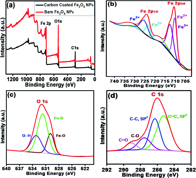 | ||
| Fig. 4 (a) XPS survey scan of bare Fe3O4 NPs and carbon-coated Fe3O4 (Fe3O4@C) core–shell NPs. HR scans of (b) Fe 2p3/2 and Fe 2p1/2 and (c) O 1s and (d) C 1s core level spectra. | ||
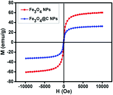
Fig. 5 shows the magnetic characterization of the small average-sized Fe3O4 NPs (ca. 5 nm) and Fe3O4@C core–shell NPs (ca. 7 nm) with respect to different magnetic fields at 300 K. An unusual behavior in magnetic properties was observed in NPs compared to their bulk counterpart. The magnetization was observed to be 60 emu g−1 for Fe3O4 NPs (ca. 5 nm), and it was obvious that there was no coercivity and remanence. Hence, the as-synthesized Fe3O4 NPs (ca. 5 nm) were found to be superparamagnetic in nature.24 Similarly, the as-synthesized Fe3O4@C core–shell NPs (ca. 7 nm) also exhibited super-paramagnetic behavior, and the magnetization was found to be 30 emu g−1 with no coercivity and remanence. The saturation magnetization was found to be much lower in the case of the core–shell NPs. The low value of the magnetic saturation may be attributed to the carbon coating over the Fe3O4 NPs as carbon materials are diamagnetic in nature.54 A low coercive field was also observed in the case of both NPs which indicate their spherical shape.55 The stabilities of the prepared ferrofluids were evaluated in terms of zeta potential and the results are shown in Table 1 and Fig. 6. The zeta potentials were measured for the different sized Fe3O4 and Fe3O4@C NP-based ferrofluids at 0.7 vol% of NPs. The results suggest coagulation/agglomeration behavior for the Fe3O4 NP-based ferrofluids (zeta potential <±5), leading to the formation of networks, whereas the Fe3O4@C NP-based ferrofluids showed moderate stability (±10 < zeta potential < ±30).56,57 An increase in the stability of NPs or their good dispersibility in the base fluid is generally observed for core–shell NPs.58,59
| Ferrofluid sample | Nanoparticles | Size (nm) | Zeta potential (mV) |
|---|---|---|---|
| 1 | Fe3O4 | 5 | 6.49 |
| 2 | Fe3O4 | 12 | −1.12 |
| 3 | Fe3O4 | 25 | −7.18 |
| 4 | Fe3O4@C | 7 | −18.7 |
| 5 | Fe3O4@C | 14 | −19.4 |
| 6 | Fe3O4@C | 28 | −20.2 |
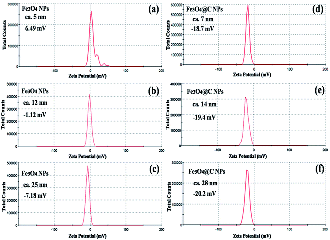 | ||
| Fig. 6 Zeta potential plots of (a) 5 nm Fe3O4, (b) 12 nm Fe3O4, (c) 25 nm Fe3O4, (d) 7 nm Fe3O4@C, (e) 14 nm Fe3O4@C and (f) 28 nm Fe3O4@C NP-based ferrofluids at 0.7 vol% NP concentration. | ||
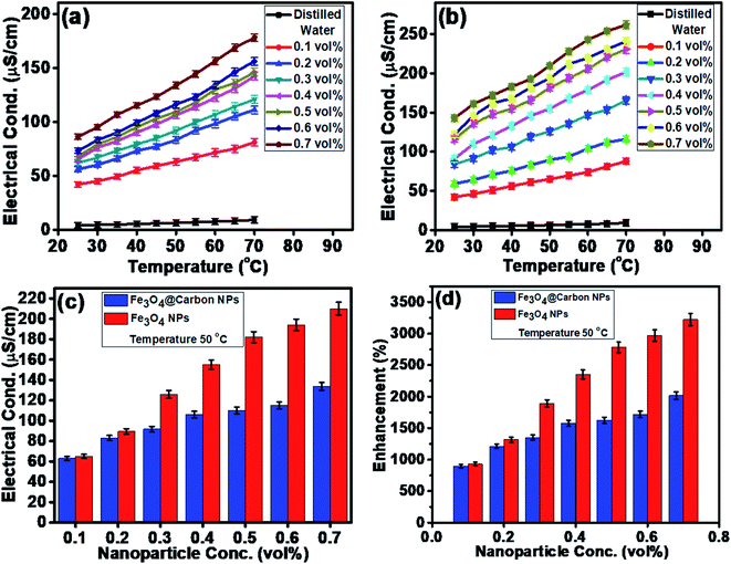
The electrical conductivities (ECs) of the as-synthesized Fe3O4 NPs (ca. 5 nm) and Fe3O4@C core–shell NP (ca. 7 nm)-based ferrofluids with different concentrations and temperature were measured. The EC of the ferrofluid was found to increase with an increase in the concentration of both types of NPs, as shown in Fig. 7a and b. Fig. 7a shows the ECs of distilled water (base fluid) and the ferrofluids with different concentrations of Fe3O4@C core–shell NPs at various temperatures. The EC of the ferrofluids was found to be many times higher than that of the base fluid. Similarly, Fig. 7b shows the ECs of Fe3O4 NP-based ferrofluids, which followed the same trend as observed in Fig. 7a for the Fe3O4@C core–shell NP-based ferrofluids. However, the ECs of the bare Fe3O4 NP-based ferrofluids were found to be higher than the core–shell NP-based ferrofluids. This may be attributed to the amorphous nature of the carbon coating, which resulted in a decrease in the EC. Fig. 7c shows a comparison of the ECs of the Fe3O4 and Fe3O4@C core–shell NP-based ferrofluids at 50 °C. It was quite obvious that the Fe3O4 NP-based ferrofluid at a particular concentration of Fe3O4 NPs exhibited a higher EC compared to the core–shell NP-based ferrofluid. Fig. 7d demonstrates the percentage enhancement in the EC compared to that of the base fluid. It was found that the Fe3O4 NP-based ferrofluid exhibited the highest value of EC, i.e., 205 μS cm−1 for 0.7 vol% of NPs at 50 °C. Conversely, the EC value of 130 μS cm−1 was recorded for the Fe3O4@C core–shell NP-based ferrofluid at the same concentration and temperature. The percentage enhancement was calculated using the following equation:
 | (2) |
The maximum enhancement in the EC of the Fe3O4 NP- and Fe3O4@C core–shell NP-based ferrofluids was obtained as ∼3222% and ∼2015%, respectively, for 0.7 vol% of NPs at 50 °C. There are many factors that affect the EC of a nanofluid or a ferrofluid such as volume fraction, temperature, structure of NPs, types of NPs, and types of fluids.60 The EC of a nanofluid/ferrofluid generally increases with an increase in the volume fraction of the nanofluid/ferrofluid and with temperature. The ions on the surface of the colloidal NPs are attracted to the oppositely charged ions, which results in the formation of a layer. Another layer of ions is also formed, where the ions from the suspension become attached to the first layer by Coulomb force, which electrically screens the first layer. The ions in the second layer are loosely associated and move due to the electric force of attraction and thermal motion. Hence, as the temperature increases, the free ions move rapidly into the suspension of the ferrofluid, which results in a high EC. An increase in the concentration of NPs also enhanced the EC as more solid NPs suspended into the fluid were available to expose their surfaces toward the ions and formed an electrical double layer. However, a relatively low EC in the case of the Fe3O4@C core–shell NPs was observed as the carbon-coated suspended Fe3O4 NPs had a lower number of electrons on their surfaces to get attracted toward the free ions compared to the bare Fe3O4 NPs. The electrons were more populated near the Fermi level in the semiconductor (Fe3O4) NPs compared to the non-metallic amorphous carbon. Hence, relatively low ECs were observed for the Fe3O4@C core–shell NP-based ferrofluids compared to the Fe3O4 NP-based ferrofluids.
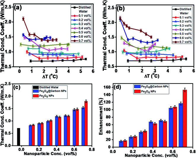
Similarly, the thermal conductivities of the Fe3O4 NP- and Fe3O4@C core–shell NP-based ferrofluids were measured. Fig. 8a and b show the graphs of the coefficient of thermal conductivity versus temperature gradient for the Fe3O4@C core–shell NP (7 nm)- and Fe3O4 NP (5 nm)-based ferrofluids, respectively. For both types of NPs, with concentrations in the range of 0.1 vol% to 0.7 vol%, it was observed that the coefficient of thermal conductivity (λ) increased consistently. The average thermal conductivity coefficients for water was found to be 0.71 W m−1 K−1, and for the ferrofluids at different concentrations of Fe3O4@C core–shell NPs, i.e., 0.1, 0.2, 0.3, 0.4, 0.5, 0.6 and 0.7 vol% they were found to be 0.82, 0.90, 0.99, 1.19, 1.22, 1.46 and 1.54 W m−1 K−1, respectively, as shown in Fig. 8a. A similar trend was observed for the Fe3O4 NP-based ferrofluids, and the values of the coefficient of thermal conductivity for various concentrations, i.e., 0.1, 0.2, 0.3, 0.4, 0.5, 0.6 and 0.7 vol% were obtained as 0.84, 0.92, 1.02, 1.16, 1.21, 1.48 and 1.80 W m−1 K−1, respectively, as shown in Fig. 8b. The comparison of thermal conductivities and percentage enhancement of Fe3O4 NP- and Fe3O4@C core–shell NP-based ferrofluids are shown in Fig. 8c and d, respectively. Fig. 8d depicts the increase in percentage enhancement with respect to DI water from 16% to 116% as the concentration of Fe3O4@C core–shell NPs varied from 0.1 vol% to 0.7 vol%. Similarly, a 17% to 153% enhancement with respect to DI water was observed for the Fe3O4 NPs as their concentration varied from 0.1 vol% to 0.7 vol%.
The maximum enhancement was observed for 0.7 vol% of Fe3O4 NPs. This may be attributed to the clustering effect of the NPs as their surface energies were quite high owing to their high surface to volume ratio and the formation of a chain-like network of small-sized NPs, which increased the effective volume fraction of heat conductive phases in the ferrofluid. Moreover, the dispersed NPs in the water-based ferrofluid executed Brownian motion, which led to collisions between the NPs and with the molecules of the water.61,62 Conversely, in the case of the Fe3O4@C core–shell NPs, the thermal capacity of the carbon coating and percolation pathways for heat conduction were responsible for the thermal conductivity enhancement.61,62 It should be noted that at only 0.7 vol%, the thermal conductivity of the Fe3O4@C core–shell NP-based ferrofluid was significantly less than that of the Fe3O4 NP-based ferrofluid. Moreover, the effects of different NPs sizes on the enhancement of the electrical and thermal conductivities were also studied, as shown in Fig. 9a and b (Fig. S2 and S3, ESI†), respectively. Fig. 9a shows the variation in the electrical conductivity enhancement of the Fe3O4 NP- and Fe3O4@C NP-based ferrofluids with NP size. The EC was found to be enhanced with a decrease in the size of the NPs for both types of ferrofluids. The increase in EC with a decrease in the NP size is attributed to the increase in surface area and electrophoretic mobility of the NPs.63,64 A similar trend was observed for the thermal conductivity enhancement, which increased with a decrease in NP size for both types of ferrofluids, as shown in Fig. 9b. The exceptional enhancement in the thermal conductivity especially in the case of the bare Fe3O4 NP (5 nm)-based ferrofluid compared to the larger-size Fe3O4 NP (12 nm and 25 nm)-based ferrofluids is due to the more pronounced effect of chain-like network formation/clustering of the NPs, as inferred from the zeta potential values (Table 1 and Fig. 6). However, owing to the carbon coating over the bare Fe3O4 NPs, relatively better dispersion and less agglomeration of the different sized Fe3O4@C NPs (as inferred from their more negative zeta potential values, Table 1 and Fig. 6) in the base fluid (water) resulted in a lower enhancement in thermal conductivity for the Fe3O4@C NP-based ferrofluids compared to the Fe3O4 NP-based ferrofluids.
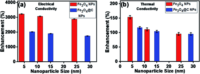 | ||
| Fig. 9 Effect of NP size on (a) electrical conductivity enhancement and (b) thermal conductivity enhancement of ferrofluids. | ||
To theoretically validate the obtained results, the experimental values of the thermal conductivities of the Fe3O4 NP (ca. 5 nm)- and Fe3O4@C NP (ca. 7 nm)-based ferrofluids were fitted with the existing Maxwell model,65 as shown in Fig. 10. Based on the effective medium theory, the effective thermal conductivity of the Fe3O4 NPs coated with carbon was calculated using the following equation:66
 | (3) |
 | (4) |
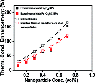 | ||
| Fig. 10 Comparison of experimental and predicted values of thermal conductivities of Fe3O4 (ca. 5 nm) and Fe3O4@C (ca. 7 nm) NP-based ferrofluids. | ||
| Material | Size (nm) | Conc./volume fraction | Base fluid | Electrical conductivity enhancement (%) | Thermal conductivity enhancement (%) | Ref. |
|---|---|---|---|---|---|---|
| Fe3O4 | 14.2 | 0.5 | Water | 360 | — | 68 |
| SiO2 | 12 | 1.1–2.4 | Water | — | 1.1 | 69 |
| TiO2 | 27 | 3.1–4.3 | 10.8 | |||
| Al2O3 | 13 | 1.3–4.3 | 32.4 | |||
| Graphene | — | 0.5/0.1 | Ethylene glycol/water | 1664 | 10.47 | 70 |
| Fe@C | — | 1.5 wt% | Polyethylene glycol | — | 30 | 39 |
| Al@C | 40 | |||||
| Cu@C | 49 | |||||
| Iron oxide(II,III) | 50 | 1 g L−1 | Water | — | 34 | 34 |
| Fe3O4 | 5–10 | 2.5 g L−1 | Mineral oil | — | 51 | 19 |
| γ-Fe2O3 | 12 | 1.5 g L−1 | 50![[thin space (1/6-em)]](https://www.rsc.org/images/entities/char_2009.gif) : :![[thin space (1/6-em)]](https://www.rsc.org/images/entities/char_2009.gif) 50 oil mixture 50 oil mixture |
— | 51 | 21 |
| CuO | 29 | 0–6 | Ethylene glycol/water | — | 60 | 71 |
| Al2O3 | 53 | 0–10 | 69 | |||
| γ-Fe2O3 | 13 | 1.5 g L−1 | Liquid paraffin/sunflower/mineral oil | — | 20.6 | 20 |
| 45.2 | ||||||
| 77 | ||||||
| Fe3O4@C | 7 | 0.7 vol% | Water | 2015 | 116 | This work |
| Fe3O4 NPs | 5 | 3222 | 153 |
4. Conclusion
In conclusion, Fe3O4 and Fe3O4@C core–shell NP-based ferrofluids were prepared to investigate their thermal and electrical conductivities. Firstly, we synthesized different sized Fe3O4 NPs via a chemical co-precipitation method using iron salts and alkali solution as precursors. The successfully synthesized Fe3O4 NPs were introduced in an autoclave with a solution of glucose at 180 °C and high pressure. The hydrothermal process enabled the formation of a carbon shell over the Fe3O4 NPs. The average particle sizes of the Fe3O4 and Fe3O4@C core shell NPs were found to be in the range of 5–25 nm and 7–28 nm, respectively. The structural and elemental analyses revealed that no phase transformation of Fe3O4 occurred during the formation of core–shell NPs. The magnetic characterization revealed that the as-synthesized small average-sized Fe3O4 NPs (ca. 5 nm) and Fe3O4@C core–shell NPs (ca. 7 nm) were superparamagnetic in nature. Finally, the electrical and thermal conductivities of the Fe3O4 and Fe3O4@C core–shell NP-based ferrofluids were measured at different concentrations of NPs and with different sized NPs. Exceptional results were obtained, where the electrical conductivity was enhanced up to ∼3222% and ∼2015% for the Fe3O4 (ca. 5 nm) and Fe3O4@C (ca. 7 nm) core–shell NP-based ferrofluids, respectively, compared to distilled water (base fluid). Similarly, the enhancement in the thermal conductivity was determined to be ∼153% and ∼116% for the Fe3O4 (ca. 5 nm) and Fe3O4@C (ca. 7 nm) core–shell NPs, respectively.Author contributions
Mohd Imran: Conceptualization, methodology, investigation, writing-original draft preparation, supervision; Nasser Zouli: visualization, investigation, supervision; Tansir Ahamad: characterization, investigation, funding; Saad M. Alshehri: characterization, investigation, funding; Mohammed Rehaan Chandan: visualization, validation, review & editing; Shahir Hussain: conceptualization, methodology, investigation, electrical conductivity experiment; Abdul Aziz: resources, thermal conductivity experiment; Mushtaq Ahmad Dar: data curation, characterization; Afzal Khan: visualization investigation, supervision, review & editing.Conflicts of interest
The authors declare no competing financial interest.Acknowledgements
The authors gratefully acknowledge the Deanship of Scientific Research at King Saud University for funding this project (RG-1438-026). The authors are also grateful to King Saud University, Riyadh, and Jazan University, Jazan, Kingdom of Saudi Arabia for providing experimental facilities.References
- W. H. Azmi, K. V. Sharma, R. Mamat, G. Najafi and M. S. Mohamad, The Enhancement of Effective Thermal Conductivity and Effective Dynamic Viscosity of Nanofluids–A Review, Renewable Sustainable Energy Rev., 2016, 53, 1046–1058 CrossRef.
- A. Gandomkar, M. H. Saidi, M. B. Shafii, M. Vandadi and K. Kalan, Visualization and Comparative Investigations of Pulsating Ferro-Fluid Heat, Appl. Therm. Eng., 2017, 116, 56–65 CrossRef CAS.
- M. A. Nazari, M. H. Ahmadi, R. Ghasempour, M. B. Shafii, O. Mahian and S. Kalogirou, et al., A Review on Pulsating Heat Pipes: From Solar to Cryogenic Applications, Appl. Energy, 2018, 222, 475–484 CrossRef.
- M. A. Nazari, M. H. Ahmadi, R. Ghasempour and M. B. Shafii, How to Improve the Thermal Performance of Pulsating Heat Pipes: A Review on Working Fluid, Renewable Sustainable Energy Rev., 2018, 91, 630–638 CrossRef.
- A. Baghban, F. Pourfayaz, M. H. Ahmadi, A. Kasaeian, S. M. Pourkiaei and G. Lorenzini, et.al., Connectionist Intelligent Model Estimates of Convective Heat Transfer Coefficient of Nanofluids in Circular Cross-Sectional Channels, J. Therm. Anal. Calorim., 2018, 132, 1213–1239 CrossRef CAS.
- M. M. Tawfik, Experimental Studies of Nanofluid Thermal Conductivity Enhancement and Applications: A Review, Renewable Sustainable Energy Rev., 2017, 75, 1239–1253 CrossRef CAS.
- S. Ponmani, J. K. M. William, R. Samuel, R. Nagarajan and J. S. Sangwai, Formation and Characterization of Thermal and Electrical Properties of CuO and ZnO Nanofluids in Xanthan Gum, Colloids Surf., A, 2014, 443, 37–43 CrossRef CAS.
- O. A. Alawi, N. A. C. Sidik, H. W. Xian, T. H. Kean and S. N. Kazi, Thermal Conductivity and Viscosity Models of Metallic Oxides Nanofluids, Int. J. Heat Mass Transfer, 2018, 116, 1314–1325 CrossRef CAS.
- W. Cui, Z. Shen, J. Yang and S. Wu, Molecular Dynamics Simulation on Flow Behaviors of Nanofluids Confined in Nanochannel, Case Stud. Therm. Eng., 2015, 5, 114–121 CrossRef.
- T. K. Hong, H. S. Yang and C. J. Choi, Study of the Enhanced Thermal Conductivity of Fe Nanofluids, J. Appl. Phys., 2005, 97, 064311 CrossRef.
- J. Garg, B. Poudel, M. Chiesa, J. B. Gordon, J. J. Ma and J. Garg, et al., Enhanced Thermal Conductivity and Viscosity of Copper Nanoparticles in Ethylene Glycol Nanofluid, J. Appl. Phys., 2008, 103, 074301 CrossRef.
- H. Zhang, Q. Wu, J. Lin, J. Chen, Z. Xu and H. Zhang, et al., Thermal Conductivity of Polyethylene Glycol Nanofluids Containing Carbon Coated Metal Nanoparticles, J. Appl. Phys., 2010, 108, 124304 CrossRef.
- M. Javed, A. H. Shaik, T. A. Khan, M. Imran, A. Aziz and A. R. Ansari, et.al. Synthesis of Stable Waste Palm Oil Based CuO Nanofluid for Heat Transfer Applications, Heat Mass Transfer, 2018, 1–7 Search PubMed.
- D. Maity and D. C. Agrawal, Synthesis of Iron Oxide Nanoparticles Under Oxidizing Environment and Their Stabilization in Aqueous and Non-Aqueous Media, J. Magn. Magn. Mater., 2007, 308, 46–55 CrossRef CAS.
- Y. Wang, C. Wang, Z. Zhang and K. Xiao, Effect of Nanoparticles on the Morphology, Thermal, and Electrical Properties of Low Density Polyethylene After Thermal Aging, Nanomaterials, 2017, 7(10), 320 CrossRef.
- D. Guo, G. Xie and J. Luo, Mechanical Properties of Nanoparticles: Basics and Applications, J. Phys. D: Appl. Phys., 2014, 47, 013001 CrossRef.
- K. L. Kelly, E. Coronado, L. L. Zhao and G. C. Schatz, The Optical Properties of Metal Nanoparticles: The Influence of Size, Shape, and Dielectric Environment, J. Phys. Chem. B, 2003, 107(3), 668–677 CrossRef CAS.
- R. Sharma, V. V. Agrawal, A. K. Srivastava, L. Nain, M. Imran and S. R. Kabi, et. al. Phase Control of Nanostructured Iron Oxide for Application to Biosensor, J. Mater. Chem. B, 2013, 14, 464–474 RSC.
- M. Imran, A. R. Ansari, A. H. Shaik, S. Hussain, A. Khan and M. R. Chandan, Ferrofluid Synthesis Using Oleic Acid Coated Fe3O4 Nanoparticles Dispersed in Mineral Oil for Heat Transfer Applications, Mater. Res. Express, 2018, 5(3), 036108 CrossRef.
- M. Imran, A. H. Shaik, A. R. Ansari, A. Aziz, S. Hussain, A. F. Fadil Abouatiaa, A. Khan and M. R. Chandan, Synthesis of Highly Stable γ-Fe2O3 Ferrofluid Dispersed in Liquid Paraffin, Motor Oil and Sunflower Oil for Heat Transfer Applications, RSC Adv., 2018, 8(25), 13970–13975 RSC.
- A. A. Abutaleb, Effect of the Mixture of Mineral/Sunflower Oil Based Ferrofluid on Thermal and Flow Properties, Mater. Res. Express, 2019, 6(4), 046101 CrossRef.
- M. Imran, A. Abutaleb, M. A. Ali, T. Ahamad, A. R. Ansari, M. Shariq, D. Lolla and A. Khan, UV Light Enabled Photocatalytic Activity of α-Fe2O3 Nanoparticles Synthesized via Phase Transformation, Mater. Lett., 2020, 258, 126748 CrossRef CAS.
- S. Xuan, L. Hao, W. Jiang, X. Gong, Y. Hu and Z. Chen, A Facile Method to Fabricate Carbon-Encapsulated Fe3O4 Core/Shell Composites, Nanotech, 2007, 18, 035602 CrossRef.
- L. Wang, K. Lin, J. Ren, K. Du, Y. Chang, L. Han, P. Yao and F. Tian, Direct Synthesis of Ultra Small and Stable Magnetite Nanoparticles Coated with One Single Carbon Layer for Sensitive Surface-Enhanced Raman Scattering, Appl. Surf. Sci., 2019, 478, 601–606 CrossRef CAS.
- C. He, S. Wu, N. Zhao, C. Shi, E. Liu and J. Li, Carbon-Encapsulated Fe3O4 Nanoparticles as a High-Rate Lithium Ion Battery Anode Material, ACS Nano, 2013, 7(5), 4459–4469 CrossRef CAS.
- N. Zhao, S. Wu, C. He, Z. Wang, C. Shi, E. Liu and J. Li, One-Pot Synthesis of Uniform Fe3O4 Nanocrystals Encapsulated in Interconnected Carbon Nanospheres for Superior Lithium Storage Capability, Carbon, 2013, 57, 130–138 CrossRef CAS.
- C. H. Liang, C. C. Wang, Y. C. Lin, C. H. Chen, C. H. Wong and C. Y. Wu, Iron Oxide/Gold Core/Shell Nanoparticles for Ultrasensitive Detection of Carbohydrate−Protein Interactions, Anal. Chem., 2009, 81(18), 7750–7756 CrossRef CAS.
- W. W. Xian, G. X. Zhu, C. J. Xia and Y. Ye, A Solution Phase Fabrication of Magnetic Nanoparticles Encapsulated in Carbon, Nanotech, 2006, 17(17), 4307 CrossRef.
- J. Li and C. Y. Liu, Carbon-Coated Copper Nanoparticles: Synthesis, Characterization and Optical Properties, New J. Chem., 2009, 33(7), 1474–1477 RSC.
- X. Sun and Y. Li, Ag@C Core/Shell Structured Nanoparticles: Controlled Synthesis, Characterization, and Assembly, Langmuir, 2005, 21(13), 6019–6024 CrossRef CAS.
- E. E. Carpenter, S. Calvin, R. M. Stroud and V. G. Harris, Passivated Iron as Core–Shell Nanoparticles, Chem. Mater., 2003, 15(17), 3245–3246 CrossRef CAS.
- W. L. Zhou, E. E. Carpenter, J. Lin, A. Kumbhar, J. Sims and C. J. O'Connor, Nanostructures of Gold Coated Iron Core-Shell Nanoparticles and the Nanobands Assembled Under Magnetic Field, Eur. Phys. J. D, 2001, 16(1), 289–292 CrossRef CAS.
- H. Cui and D. Li, Fabrication and Properties Research on a Novel Perfluoropolyether Based Ferrofluid, J. Magn. Magn. Mater., 2019, 473, 341–347 CrossRef CAS.
- J. Župan and M. M. Renjo, Thermal and Rheological Properties of Water-Based Ferrofluids and Their Applicability as Quenching Media, Phys. Procedia, 2015, 75, 1458–1467 CrossRef.
- A. Gavili, F. Zabihi, T. D. Isfahani and J. Sabbaghzadeh, The Thermal Conductivity of Water Base Ferrofluids Under Magnetic Field, Exp. Therm. Fluid Sci., 2012, 41, 94–98 CrossRef CAS.
- S. Dutz, J. H. Clement, D. Eberbeck, T. Gelbrich, R. Hergt and R. Müller, et al., Ferrofluids of Magnetic Multicore Nanoparticles for Biomedical Applications, J. Magn. Magn. Mater., 2009, 321(10), 1501–1504 CrossRef CAS.
- V. M. Wu, E. Huynh, S. Tang and V. Uskoković, Brain and Bone Cancer Targeting by a Ferrofluid Composed of Superparamagnetic Iron-Oxide/Silica/Carbon Nanoparticles, Actabiomater, 2019, 88, 422–447 CrossRef CAS.
- G. Kandasamy, A. Sudame, D. Maity, S. Soni, K. Sushmita and N. S. Veerapu, et al., Multifunctional Magnetic-Polymeric Nanoparticles Based Ferrofluids for Multi-Modal in Vitro Cancer Treatment Using Thermotherapy and Chemotherapy, J. Mol. Liq., 2019, 293, 111549 CrossRef CAS.
- A. Kaushik, J. Rodriguez, D. Rothen, V. Bhardwaj, R. D. Jayant, P. Pattany and B. Fuentes, et al., MRI-guided, Non-invasive Delivery of Magneto-electric Drug Nanocarriers to the Brain in a Nonhuman Primate, ACS Appl. Bio Mater., 2019, 2, 4826–4836 CrossRef CAS.
- P. Pandey, G. Ghimire, J. Garcia, A. Rubfiaro, X. Wang, A. Tomitaka, M. Nair, A. Kaushik and J. He, Single-entity Approach to Investigate Surface Charge Enhancement in Magnetoelectric Nanoparticles Induced by AC Magnetic Field Stimulation, ACS Sens., 2020 DOI:10.1021/acssensors.0c00664.
- A. Tomitaka, A. Kaushik, B. D. Kevadiya, I. Mukadam, H. E. Gendelman, K. Khalili, G. Liu and M. Nair, Surface-engineered Multimodal Magnetic Nanoparticles to Manage CNS Diseases, Drug Discovery Today, 2019, 24, 873–882 CrossRef CAS.
- A. Kaushik, R. N. Moshaie, R. Sinha, V. Bhardwaj, V. Atluri, R. D. Jayant, A. Yndart, B. Kateb, N. Pala and M. Nair, Investigation of AC-Magnetic Field Stimulated Nanoelectroporation of Magneto-electric Nano-drug-carrier Inside CNS Cells, Sci. Rep., 2017, 7, 1–12 CrossRef.
- A. Kaushik, A. Yndart, V. Atluri, S. Tiwari, A. Tomitaka, P. Gupta, R. D. Jayant, D. A. Carbonell, K. Khalili and M. Nair, Magnetically Guided Non-invasive CRISPR-Cas9/gRNA Delivery Across Blood-brain Barrier to Eradicate Latent HIV-1 Infection, Sci. Rep., 2019, 9, 1–11 CrossRef CAS.
- K. V. Chandekar, M. Shkir, T. Alshahrani, E. H. Ibrahim, M. Kilany, Z. Ahmad, M. A. Manthrammel, S. AlFaify, B. Kateb and A. Kaushik, One-spot Fabrication and In-vivo Toxicity Evaluation of Core-shell Magnetic Nanoparticles, Mater. Sci. Eng., C, 2021, 111898 CrossRef CAS.
- R. Kumar, K. Mondal, P. K. Panda, A. Kaushik, R. Abolhassani, R. Ahuja, H. G. Rubahn and Y. K. Mishra, Core–shell Nanostructures: Perspectives Towards Drug Delivery Applications, J. Mater. Chem. B, 2020, 8, 8992–9027 RSC.
- M. Imran, A. A. A. Ahmed, B. Kateb and A. Kaushik, Inorganic Nanostructures for Brain Tumor Management, in Nanotherapy for Brain Tumor Drug Delivery, Humana, New York, 2021, pp. 145–178 Search PubMed.
- H. Zhang, Q. Wu, J. Lin, J. Chen and Z. Xu, Thermal Conductivity of Polyethylene Glycol Nanofluids Containing Carbon Coated Metal Nanoparticles, J. Appl. Phys., 2010, 108(12), 124304 CrossRef.
- T. T. Baby and R. Sundara, Surfactant Free Magnetic Nanofluids Based on Core-shell Type Nanoparticle Decorated Multiwalled Carbon Nanotubes, J. Appl. Phys., 2011, 110(6), 064325 CrossRef.
- D. Fan, Q. Li, W. Chen and J. Zeng, Graphene Nanofluids Containing Core-Shell Nanoparticles with Plasmon Resonance Effect Enhanced Solar Energy Absorption, Sol. Energy, 2017, 158, 1–8 CrossRef CAS.
- R. Islam and B. Shabani, Prediction of Electrical Conductivity of TiO2 Water and Ethylene Glycol-Based Nanofluids for Cooling Application in Low Temperature PEM Fuel Cells, Energy Procedia, 2019, 160, 550–557 CrossRef CAS.
- G. Zhao, J. J. Feng, Q. L. Zhang, S. P. Li and H. Y. Chen, Synthesis and Characterization of Prussian Blue Modified Magnetite Nanoparticles and Its Application to the Electrocatalytic Reduction of H2O2, Chem. Mater., 2005, 17(12), 3154–3159 CrossRef CAS.
- K. Tao, H. Dou and K. Sun, Facile Interfacial Co-Precipitation to Fabricate Hydrophilic Amine-Capped Magnetite Nanoparticles, Chem. Mater., 2006, 18(22), 5273–5278 CrossRef CAS.
- M. I. Dar and S. A. Shivashankar, Single Crystalline Magnetite, Maghemite, and Hematite Nanoparticles with Rich Coercivity, RSC Adv., 2014, 4(8), 4105–4113 RSC.
- D. Ağaoğulları, S. J. Madsen, B. Ögüt, A. L. Koh and R. Sinclair, Synthesis and Characterization of Graphite-Encapsulated Iron Nanoparticles From Ball Milling-Assisted Low-Pressure Chemical Vapor Deposition, Carbon, 2017, 124, 170–179 CrossRef.
- H. Hu, Y. Yuan, S. Lim and C. H. Wang, Phase Structure Dependence of Magnetic Behaviour in Iron Oxide Nanorods, Mater. Des., 2020, 185, 108241 CrossRef CAS.
- M. L. O. Pereira, K. C. B. Maia, W. C. Silva, A. C. Leite, A. D. S. Francisco, T. L. Vasconcelos, R. S. V. Nascimento and D. Grasseschi, Fe3O4 Nanoparticles as Surfactant Carriers for Enhanced Oil Recovery and Scale Prevention, ACS Appl. Nano Mater., 2020, 3(6), 5762–5772 CrossRef CAS.
- S. Wu, D. Zhu, X. Li, H. Li and J. Lei, Thermal Energy Storage Behavior of Al2O3–H2O Nanofluids, Thermochim. Acta, 2009, 483, 73–77 CrossRef CAS.
- X. Q. Xu, H. Shen, J. R. Xu, M. Q. Xie and X. J. Li, The Colloidal Stability and Core-Shell Structure of Magnetite Nanoparticles Coated with Alginate, Appl. Surf. Sci., 2006, 253(4), 2158–2164 CrossRef CAS.
- G. Kandasamy, A. Sudame, T. Luthra, K. Saini and D. Maity, Functionalized Hydrophilic Superparamagnetic Iron Oxide Nanoparticles for Magnetic Fluid Hyperthermia Application in Liver Cancer Treatment, ACS Omega, 2018, 3, 3991–4005 CrossRef CAS.
- J. Philip, P. D. Shima and B. Raj, Enhancement of Thermal Conductivity in Magnetite Based Nanofluid Due to Chain Like Structures, Appl. Phys. Lett., 2007, 91, 203108 CrossRef.
- P. Keblinski, S. R. Phillpot, S. U. S. Choi and J. A. Eastman, Mechanisms of Heat Flow in Suspensions of Nano-Sized Particles, Int. J. Heat Mass Transfer, 2002, 45(4), 855–863 CrossRef CAS.
- S. Bagheli, H. K. Fadafan, R. L. Orimi and M. Ghaemi, Synthesis and Experimental Investigation of the Electrical Conductivity of Water Based Magnetite Nanofluids, Powder Technol., 2015, 274, 426–430 CrossRef CAS.
- K. K. Sarojini, S. V. Manoj, P. K. Singh, T. Pradeep and S. K. Das, Electrical Conductivity of Ceramic and Metallic Nanofluids, Colloids Surf., A, 2013, 417, 39–46 CrossRef CAS.
- H. Konakanchi, R. Vajjha, D. Misra and D. Das, Electrical Conductivity Measurements of Nanofluids and Development of New Correlations, J. Nanosci. Nanotechnol., 2011, 11, 6788–6795 CrossRef CAS.
- J. C. Maxwell, A Treatise on Electricity and Magnetism, Dover Publications, New York, 1954 Search PubMed.
- L. M. Schwartz, E. J. Garboczi and D. P. Bentz, Interfacial Transport in Porous Media: Application to DC Electrical Conductivity of Mortars, J. Appl. Phys., 1995, 78(10), 5898–5908 CrossRef CAS.
- C. Kleinstreuer and Y. Feng, Experimental and Theoretical Studies of Nanofluid Thermal Conductivity Enhancement: A Review, Nanoscale Res. Lett., 2011, 6, 229 CrossRef.
- H. Masuda, A. Ebata, K. Teramae, N. Hishinuma and Y. Ebata, Alteration of Thermal Conductivity and Viscosity of Liquid by Dispersing Ultra-Fine Particles, Netsu Bussei, 1993, 7(4), 227–233 CrossRef CAS.
- A. Ijam, R. Saidur, P. Ganesan and A. M. Golsheikh, Stability, Thermo-Physical Properties, and Electrical Conductivity of Graphene Oxide-Deionized Water/Ethylene Glycol Based Nanofluid, Int. J. Heat Mass Transfer, 2015, 87, 92–103 CrossRef CAS.
- R. S. Vajjha and D. K. Das, Experimental Determination of Thermal Conductivity of Three Nanofluids and Development of New Correlations, Int. J. Heat Mass Transfer, 2009, 52, 4675–4682 CrossRef CAS.
- Y. Geng, H. Khodadadi, A. Karimipour, M. R. Safaei and T. K. Nguyen, A Comprehensive Presentation on Nanoparticles Electrical Conductivity of Nanofluids: Statistical Study Concerned Effects of Temperature, Nanoparticles Type and Solid Volume Concentration, Phys. A, 2019, 123432 Search PubMed.
Footnote |
| † Electronic supplementary information (ESI) available. See DOI: 10.1039/d1na00061f |
| This journal is © The Royal Society of Chemistry 2021 |

