 Open Access Article
Synthesis of naked vanadium pentoxide nanoparticles
Patrick
Taylor
*a,
Matthew
Kusper
*a,
Tina
Hesabizadeh
a,
Luke D.
Geoffrion
 a,
Fumiya
Watanabe
 b,
Etienne
Herth
c and
Grégory
Guisbiers
 a
a
aDepartment of Physics and Astronomy, University of Arkansas at Little Rock, 2801 South University Avenue, Little Rock, AR 72204, USA. E-mail: gxguisbiers@ualr.edu
bCenter for Integrative Nanotechnology Sciences, University of Arkansas at Little Rock, 2801 South University Avenue, Little Rock, AR 72204, USA
cCentre de Nanosciences et de Nanotechnologies, CNRS UMR 9001, Univ. Paris-Sud, Université Paris-Saclay, 91120, Palaiseau, France
First published on 17th February 2021
Abstract
Vanadium pentoxide is the most important vanadium compound by being the precursor to most vanadium alloys. It also plays an essential role in the production of sulfuric acid as well as in metal-ion batteries and supercapacitors. In this paper, pulsed laser ablation in liquids is used to synthesize “naked” vanadium pentoxide nanostructures. The resulting particles take up “nearly-spherical” and “flower-like” morphologies, composed of α-V2O5 and β-V2O5 crystalline phases. Even “naked”, the nanostructures are stable in time with a zeta potential of −51 ± 7 mV. In order to maximize the production of vanadium pentoxide nanostructure, the optimal repetition rate was determined to be @ ∼6600 Hz when irradiating a pure vanadium target in DI-water. This corresponds to a cavitation bubble lifetime of around ∼0.15 ms. At that repetition rate, the production reached ∼10 ppm per minute of irradiation. Finally, from the characterization of the α-V2O5 and β-V2O5 nanostructures, the surface energy of each phase has been carefully determined at 0.308 and 1.483 J cm−2, respectively. Consequently, the β-phase was found to display a surface energy very close to platinum. The exciton Bohr radius has been determined at 3.5 ± 0.7 nm and 2.0 ± 0.6 nm for α-V2O5 and β-V2O5 phases, respectively.
1 Introduction
Vanadium (V) is a transition metal discovered in 1801 by the mineralogist Andrés Manuel del Río in Mexico.1 It is the 6th most abundant transition metal on Earth, the 21st most abundant chemical element in the Earth's crust and the 2nd most abundant chemical element in seawater.2–5 The world top 3 producers and reserve holders are China, South Africa and Russia.2,6 Domestically, the United States has reserves estimated to 45![[thin space (1/6-em)]](https://www.rsc.org/images/entities/char_2009.gif) 000 tons. Utah is the primary producer with its White Mesa mill located South East of the state on the Colorado Plateau; while Arkansas, Delaware, Ohio, Pennsylvania and Texas are secondary producers.6 The importance of vanadium in chemistry is due to its wide range of oxidation states. Indeed, vanadium is often found in oxides with the following oxidation states +5 (V2O5), +4 (VO2), +3 (V2O3) and even +2 (VO). The most important oxide is vanadium pentoxide (V2O5, also known as vanadia) which is used as a catalyst for the production of sulfuric acid.5 Platinum used to be the catalyst for this chemical reaction; however, as platinum reacts with arsenic impurities possibly present in the sulphur feedstock, V2O5 is now preferred. V2O5 is also suitable in electrochemical applications.7,8 Indeed, V2O5 has been extensively studied as electrode materials in lithium-ion batteries (LIBs),9–11 in aluminum-ion batteries (AIBs),12 zinc-ion batteries (ZIBs)13,14 and in supercapacitors15,16 due to its unique crystalline structure. It is also used as a nano-powder in latent finger print detection (LFPD).17 Furthermore, the surface of V2O5 undergoes an insulator–metal transition (IMT) around ∼350–550 K (ref. 18 and 19) and this property has been successfully used to build nitrogen dioxide sensors.20 Additionally, V2O5 is also used in photo-detectors.21
000 tons. Utah is the primary producer with its White Mesa mill located South East of the state on the Colorado Plateau; while Arkansas, Delaware, Ohio, Pennsylvania and Texas are secondary producers.6 The importance of vanadium in chemistry is due to its wide range of oxidation states. Indeed, vanadium is often found in oxides with the following oxidation states +5 (V2O5), +4 (VO2), +3 (V2O3) and even +2 (VO). The most important oxide is vanadium pentoxide (V2O5, also known as vanadia) which is used as a catalyst for the production of sulfuric acid.5 Platinum used to be the catalyst for this chemical reaction; however, as platinum reacts with arsenic impurities possibly present in the sulphur feedstock, V2O5 is now preferred. V2O5 is also suitable in electrochemical applications.7,8 Indeed, V2O5 has been extensively studied as electrode materials in lithium-ion batteries (LIBs),9–11 in aluminum-ion batteries (AIBs),12 zinc-ion batteries (ZIBs)13,14 and in supercapacitors15,16 due to its unique crystalline structure. It is also used as a nano-powder in latent finger print detection (LFPD).17 Furthermore, the surface of V2O5 undergoes an insulator–metal transition (IMT) around ∼350–550 K (ref. 18 and 19) and this property has been successfully used to build nitrogen dioxide sensors.20 Additionally, V2O5 is also used in photo-detectors.21
Vanadium pentoxide has three polymorphs, α-V2O5 (orthorhombic), β-V2O5 (monoclinic or tetragonal) and δ-V2O5 (orthorhombic).22 The α-V2O5 phase is the most stable phase and the other two phases can be obtained under high pressure and high temperature.
V2O5 nanostructures (NSs) has been produced by wet-chemistry23 and pulsed laser deposition.24 But only a small number of groups have investigated the synthesis of vanadium oxide NSs by Pulsed Laser Ablation in Liquids (PLAL).25,26 PLAL synthesis has several advantages compared to wet-chemistry, the main one is that the surface of the synthesized nanoparticles is totally free of any contaminants i.e. left-over from chemical reactions or surfactants. This surface purity is really important for nanoparticles used as catalysts or bio-medical agents. In this work, we present a new synthesis protocol to produce “naked” (i.e. free of any contaminants) V2O5 NSs. Those V2O5 NSs are great candidates to be used in catalytic and biomedical applications. The synthesis and characterization are detailed in Sections 2 and 3, respectively. The results and discussion are mentioned in Sections 4 and 5, respectively. Finally, the conclusions are described in Section 6.
2 Materials and methods
A Q-switched Nd:YAG laser from Electro Scientific Industries operating @ 1064 nm was used to irradiate a vanadium target. Bulk vanadium flakes (99.5% from Johnson Matthey) were used as the target in this experiment. The dimensions of the flakes are ∼2 mm by ∼2 mm. The flakes were rinsed in DI water and then immersed in 5 ml of DI water, contained in a 50 ml rounded single neck glass flask. Consequently, the height of the liquid above the surface of the target was measured to be 8 mm. The pulse repetition rate of the laser was varied from 1 kHz to 10 kHz. Consequently, the pulse duration time varied slightly from 70 ns to 200 ns depending on the repetition rate. The laser shined a pulsed beam with an energy per pulse around 10 mJ per pulse @ 1000 Hz. The beam was deflected by a flat mirror oriented @ 45° angle (with respect to the laser rail) in order to irradiate the target from the top and was then focused by using an 83 mm focal length lens. The beam's spot size on the target was measured by scanning electron microscopy (SEM) to be around ∼45 μm. Therefore, the intensity of the laser is determined to be around ∼8 × 10⁵ W cm−2. At 1000 Hz, the fluence is calculated to be ∼6 × 10 2 J cm−2. The target was finally irradiated for 5 min.The colloidal solutions were characterized by UV-visible spectroscopy (Cary 60 from Agilent), Atomic Emission Spectroscopy (4210 MP-AES from Agilent), Raman Spectroscopy (EZRaman-N from Enwave Optronics, Inc.), X-ray diffraction (Bruker D8-Discover Diffractometer), X-ray Photoelectron Spectroscopy (K-Alpha XPS from Thermo Scientific), Dynamic Light Scattering (NanoBrook 90Plus Zeta from Brookhaven Instruments Corporation), Scanning Electron Microscopy (JEOL JSM – 7000F SEM, equipped with a field emission gun and operating at 30 kV) and Transmission Electron Microscope (JEOL-JEM-2100F TEM operating at 80 kV).
To perform Raman, XRD and SEM analysis, a droplet of the colloidal solution was deposited onto a silicon wafer and dried in an environmentally controlled glove box. The TEM analysis was performed using a copper TEM grid. X-ray Photoelectron Spectroscopy (XPS) has been performed by using the following etching condition, 200 eV for 20 seconds. The XPS spectra was analyzed with the fitting software, called Avantage.
3 Results
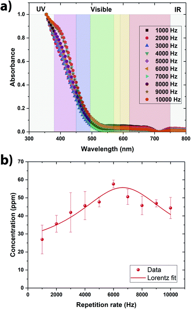
From the direct observation of all the colloidal solutions, it is observed that they all exhibit a yellow color (Fig. 2a). The vanadium oxide stoichiometry of the NSs can be guessed directly from the color of the colloidal solution.9 Indeed, vanadium exhibits four common oxidation states +5, +4, +3, and +2, each of which can be distinguished by its color, yellow for +5, blue for +4, green for +3 and violet for +2.9 As the color of the colloidal solutions obtained by pulsed laser ablation is yellow, it is evident that V2O5 has been produced (Fig. 1a). By shining a pointer laser beam through each sample, the Tyndall effect was observed as illustrated in Fig. 1b. Indeed, the Tyndall effect is the scattering of light as a laser beam passes through a colloidal solution. The presence of particles scatter and reflect the laser light, making the laser beam visible.27,28 The high oxidation state of vanadium make the NSs absorbing mainly in the violet region, consequently displaying the complementary color in the yellow region (Fig. 2a). From the UV-visible spectroscopy analysis, it seems that the colloidal solutions synthesized at 6000 Hz and 7000 Hz were the ones that absorbs the most in the UV-visible region meaning consequently that they contain the largest amount of NSs (Fig. 2a).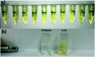 | ||
Fig. 1 (a) Photo of the colloidal solutions synthesized at different repetition rate from 1000 Hz to 10![[thin space (1/6-em)]](https://www.rsc.org/images/entities/char_2009.gif) 000 Hz. (b) Tyndall effect observed on one of the V2O5 colloidal solution. 000 Hz. (b) Tyndall effect observed on one of the V2O5 colloidal solution. | ||
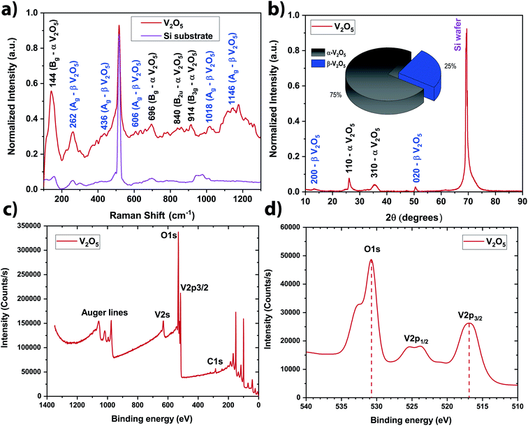
In order to be quantitative, the vanadium concentration contained in each colloidal solution was determined by Atomic Emission Spectroscopy (AES). The data were plotted in Fig. 2b. By fitting the data, the optimal repetition rate producing the highest vanadium concentration was determined to be around 6652 Hz ± 290 Hz. By taking the reciprocal value of this repetition rate, the cavitation bubble lifetime can be estimated around 0.15 ms ± 0.01 ms. This value is similar to the one obtained when irradiating metallic target in deionized water.29–32 Hitting the target at the repetition rate higher than 6652 Hz is not going to produce more nanoparticle in solution because the laser beam is going to hit the cavitation bubble shielding the target from the beam. Therefore, in a static configuration (the laser beam hits always the same spot on the target), the optimal repetition rate was set to 6600 Hz (the smallest repetition rate increment on the ESI laser is 100 Hz). At this repetition rate, the vanadium concentration in the colloidal solution reaches ∼55 ppm within 5 min of irradiation (Fig. 2b). As V2O5 has several polymorphs, Raman spectroscopy and XRD analysis were performed to determine the exact crystalline structure of V2O5 contained in the colloidal solution. The crystalline structure adopted by the NSs produced @ 6600 Hz was the α- and β-V2O5 phases as shown by the Raman and XRD spectra (Fig. 3a and b).7,35 As shown in the inset of Fig. 3b, the quantities of α- and β-phases of V2O5 have been evaluated to 75% and 25%, respectively, by calculating the surface area underneath each peak. The β-phase is the first high pressure phase of V2O5 obtained from α-V2O5 by the application of isotropic pressure between 4 to 10 GPa at temperatures between room temperature and 1023 K.36 Based on the synthesis conditions encountered in PLAL, the α-phase seems to be produced during the early stages of bubble expansion while the β-phase seems to be produced at the end during the cavitation bubble collapse.37 By using the Scherrer equation,38 the crystallite size in both phases has been determined around ∼13 nm and ∼6 nm for the α- and β-V2O5 phases. Furthermore, the XPS spectra are shown on Fig. 3c and d. The C 1s, O 1s, and V 2p core levels were measured. The peak located at ∼517 eV corresponds to the V5+ oxidation state meaning that V2O5 is found at the surface of the NSs.39–41
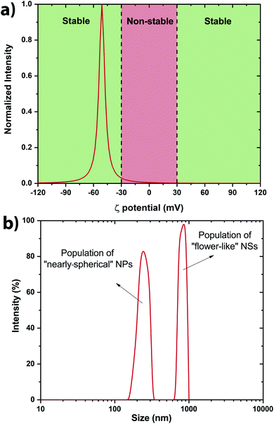
The stability of the NSs present within the colloidal solution has been determined by measuring the ζ potential.42,43 It has been measured at −51 ± 7 mV indicating a stable colloidal solution (Fig. 4a). Indeed, solutions with ζ potential smaller than −30 mV or larger than +30 mV are considered as stable. The negative sign of the ζ potential means that the net charge of the scattering NS is negative. This prevents the structure from further reacting within its own environment. A rough estimation of the size distribution has been performed by Dynamic Light Scattering (DLS) revealing two main populations within the colloidal solutions (Fig. 4b). Scanning electron microscopy (SEM) was also performed to determine accurately the morphology of the V2O5 NSs.
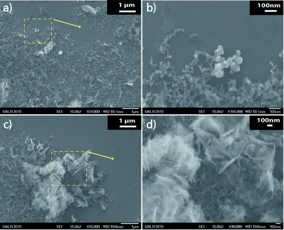
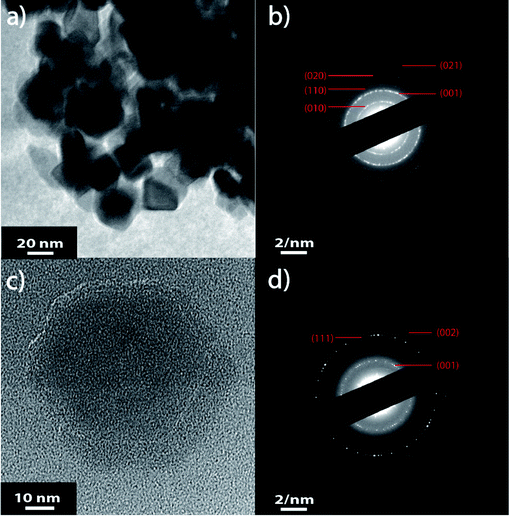
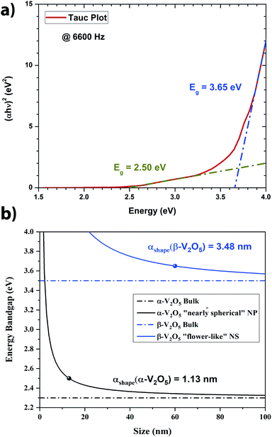
From Fig. 5, it is clear that two main populations were produced. One population is made of “nearly-spherical” NPs with sizes below 100 nm. The other population is made of “flower-like” type of NSs with an overall size of almost a micron. The flower like structure seems to be linked to the natural tendency of V2O5 to grow as a monolayer.44 Furthermore, a closer look at the NSs by Transmission Electron Microscopy (TEM) revealed that the “nearly-spherical” NPs were adopting an α-phase V2O5 while the “flower-like” type NSs were adopting the β-phase V2O5 (Fig. 6). Finally, the energy bandgap of both types of NSs was determined by using the Tauc plot (Fig. 7). The Tauc plot is achieved by plotting (αhν)1/rversus the energy of light using 1/2 as numerical value for the parameter r. The value of r denotes the nature of the transition: r = 1/2 for a direct transition while r = 2 for an indirect transition. By extrapolating the linear regime of the Tauc plot to the abscissa yields to the energy bandgap.45,46 From Fig. 7, two energies bandgap were determined at 2.50 eV and 3.65 eV, both corresponding to a direct transition. At the bulk scale, the energies bandgap of α- and β-V2O5 have been determined at 2.30 and 3.45 eV, respectively.47,48 Therefore, it is normal to measure a slightly larger value for each energy bandgap due size effects affecting material properties at the nanoscale.49,50
4 Discussion
The first paper reporting the synthesis of vanadium pentoxide nanoparticles by PLAL was published by Celestino-Santos et al.33 in 2011. The particles were distributed into two populations, one around ∼10 nm and another one around ∼60 nm. The nanoparticles are a mixture of amorphous and β-V2O5 phases. The second paper from the same group was published in 2012 by Bezerra et al.34 who also reported the synthesis of β-V2O5 NPs. The size of nanoparticles ranges from a couple of nm to more than 100 nm.In this paper, α- and β-V2O5 NSs were obtained by irradiating, at high repetition rate i.e. in the kHz regime, a target made of vanadium flakes immerged into de-ionized (DI) water. A new morphology was synthesized beside the “nearly spherical” NPs, and it looks like a “flower-like” NSs. All the groups used either distilled or de-ionized water as solvent. All the groups used a nanosecond laser meaning that the pulse duration is in the nanosecond regime. A table summarizing the synthesis conditions of all the groups is shown in Table 1.
| Parameters | Ref. 33 | Ref. 34 | This work |
|---|---|---|---|
| Type of laser | Nd:YAG | Nd:YAG | Nd:YAG |
| Wavelength | 1064 nm | 1064 nm | 1064 nm |
| Repetition rate | 0.3 kHz | 1 kHz | 1–10 kHz |
| Pulse duration | 150 ns | 200 ns | 75–200 ns |
| Fluence | ∼80 J cm−2 | ∼80 J cm−2 | 76–764 J cm−2 |
| Irradiation time | 10 min | 265 min | 5 min |
| Solvent | Distilled water | Distilled water | DI water |
| Populations | 2 | 1 | 2 |
| Size | ∼10 nm & ∼60 nm | ∼6 nm | ∼13 nm & x ∼ 200 nm, y ∼ 300 nm and z ∼ 60 nm |
| Crystalline structure | β-V2O5 | β-V2O5 | α-V2O5; β-V2O5 |
| Morphology | Spherical NPs | Spherical NPs | Nearly-spherical NPs; “flower-like NSs” |
| Potential application | Biomedical sensor | Biomedical sensor | Catalyst |
To be complete, there is a paper published in 2019 by Val'yano et al.51 who reported the synthesis of V16O3 by PLAL. The average nanoparticle size was around ∼45 nm. Most of the synthesized nanoparticles were amorphous. The target was rotating at 2 rpm so the irradiation spot was circularly displaced on the target surface. Therefore, the key parameters to produce those “flower-like” V2O5 NSs seems to be the larger fluence used in this paper and the higher repetition rate.
Theoretically, the size effect on the energy bandgap of V2O5 can be predicted by using nano-thermodynamics.49 According the theory, the energy bandgap of the nanostructure can be expressed as:
 | (1) |
 | (2) |
In Fig. 7a, the energy difference, ΔEg, between the V2O5 nanostructure and the bulk has been determined to be 0.2 eV. Therefore, by using the Scherrer equation on the XRD spectra (Fig. 7b) the crystallite size has been determined around 13 nm for the α-V2O5 nanostructure. By assuming the crystallite size is the same as the size of the nanostructure, the αshape parameter for an α-V2O5 sphere has been determined at 1.13 nm. By assuming a rectangular morphology for the β-V2O5 flake having the following dimensions, x ∼ 200 nm, y ∼ 300 nm and z ∼ 60 nm, is estimated to be around 3.48 nm. It is possible to predict the surface energy of α-V2O5 and β-V2O5 by using the definition of αshape. Indeed, αshape is defined as:
 | (3) |
From Table 2, and γl are well known experimentally; the surface to volume ratio of the α-V2O5 nanostructures is very similar to the one of a sphere (∼6/D). Therefore, by using αshape = 1.13 nm, γs is predicted to be around 0.308 J m−2. This value is well within the range of theoretical values, 0.171 and 0.893 J m−2, announced by Kristoffersen et al. for α-V2O5 (ref. 56) as well as the range of theoretical values 0.047 and 0.550 J m−2 reported by Goclon et al.57 By using αshape = 3.48 nm for the β-V2O5 flake, the γs is predicted to be around 1.483 J m−2. It makes sense to get a larger surface energy value for the β-V2O5 phase than for the α-V2O5 phase, as the α-V2O5 is the most thermodynamically stable. Higher surface energies generally correspond to higher surface chemical reactivities; consequently, β-V2O5 flake is more catalytically active than α-V2O5.58 Furthermore, the surface energy of β-V2O5 flake is very close to the one of Platinum (Pt). Indeed, the surface energy of Pt ranges between 1.464 and 1.935 J m−2 depending on its crystalline orientation.58
By using the following equation, the atomic Bohr radius of V2O5 can also be predicted:50
| log(aB,ex) = a + b × log(Eg) | (4) |
Consequently, in order to obtain quantum nanostructures of V2O5 with the PLAL protocol, it is necessary to increase the irradiation time. This can be done by adding a second step irradiation to the current protocol; indeed, the first step is to produce the nanostructures in solution by irradiating the target, while the second step would just irradiate the colloidal solution without the target being present.
5 Conclusion
Vanadium pentoxide nanostructures have been successfully synthesized by PLAL. It is the first time that “naked” V2O5 NSs were successfully synthesized by PLAL. The colloidal solution was very stable with time with a zeta potential of −51 ± 7 mV. The lifetime of the cavitation bubble (∼0.15 ms) and the optimal repetition rate (∼ 6600 Hz) have been determined when the target was kept static with respect to the laser beam. Two main population of NSs have been produced such as “nearly-spherical” NPs and “flower-like” type of NSs. The “nearly-spherical” NPs adopted an α-V2O5 phase while the “flower-like” NSs adopted a β-V2O5 phase. Furthermore, the surface energies of α- and β-phases have been estimated to 0.308 and 1.483 J m−2, respectively. Additionally, the bandgap energy is determined to be 2.5 and 3.48 eV for the “nearly spherical” NPs and “flower-like” type of NSs, respectively. Finally, a two-steps irradiation protocol is under development to synthesize V2O5 quantum structures. Future work will focus on promoting the flower-like nanostructures, as they have similar surface energy to Pt, which makes it a candidate to replace Pt in most chemical reactions. More work is underway to promote the growth of naked “flower-like” nanostructures with a β-V2O5 phase in order to design cheaper catalysts and make the synthesis protocol shape-selective.Conflicts of interest
There are no conflicts to declare.Acknowledgements
The authors are grateful to the Center for Integrative Nanotechnology Sciences (CINS) of UA Little Rock for sharing their instruments (SEM, TEM and XPS) and partly supported by the french RENATECH network. Finally, P. Taylor and T. Hesabizadeh would also like to thank the McNair Research Program for their financial support.Notes and references
- https://www.rsc.org/periodic table/element/23/vanadium .
- E. F. Baroch, Vanadium and vanadium alloys, 2013 Search PubMed.
- D. Rehder, Met. Ions Life Sci., 2013, 13, 139–169 CrossRef.
- W. H. Schlesinger, E. M. Klein and A. Vengosh, Proc. Natl. Acad. Sci. U. S. A., 2017, 114, E11092–E11100 CrossRef CAS.
- R. R. Langeslay, D. M. Kaphan, C. L. Marshall, P. C. Stair, A. P. Sattelberger and M. Delferro, Chem. Rev., 2019, 119, 2128–2191 CrossRef CAS.
- https://pubs.usgs.gov/periodicals/mcs2020/mcs2020%20vanadium.pdf .
- R. Baddour-Hadjean, M. B. Smirnov, K. S. Smirnov, V. Y. Kazimirov, J. M. Gallardo-Amores, U. Amador, M. E. Arroyo-de Dompablo and J. P. Pereira-Ramos, Inorg. Chem., 2012, 51, 3194–3201 CrossRef CAS.
- I. Mjejri, M. Gaudon, G. Song, C. Labrugère and A. Rougier, ACS Appl. Energy Mater., 2018, 1, 2721–2729 CrossRef CAS.
- Y. Yue and H. Liang, Adv. Energy Mater., 2017, 7, 1602545 CrossRef.
- Y. Zhang, Y. Wang, Z. Xiong, Y. Hu, W. Song, Q. Huang, X. Cheng, L.-Q. Chen, C. Sun and H. Gu, ACS Omega, 2017, 2, 793–799 CrossRef CAS.
- W. Zhong, J. Huang, S. Liang, J. Liu, Y. Li, G. Cai, Y. Jiang and J. Liu, ACS Energy Lett., 2020, 5, 31–38 CrossRef CAS.
- A. M. Diem, B. Fenk, J. Bill and Z. Burghard, Nanomaterials, 2020, 10, 247 CrossRef CAS.
- F. Liu, Z. Chen, G. Fang, Z. Wang, Y. Cai, B. Tang, J. Zhou and S. Liang, Nano-Micro Lett., 2019, 11, 25 CrossRef CAS.
- Y. Yang, Y. Tang, G. Fang, L. Shan, J. Guo, W. Zhang, C. Wang, L. Wang, J. Zhou and S. Liang, Energy Environ. Sci., 2018, 11, 3157–3162 RSC.
- B. Balamuralitharan, I.-H. Cho, J. S. Bak and H. J. Kim, New J. Chem., 2018, 42, 11862–11868 RSC.
- D. Majumdar, M. Mandal and S. K. Bhattacharya, ChemElectroChem, 2019, 6, 1623–1648 CrossRef CAS.
- G. R. Navyashree, K. Hareesh, H. Nagabhushana, G. Nagaraju and D. V. Sunitha, Mater. Res. Express, 2019, 6, 084003 CrossRef CAS.
- M. Kang, I. Kim, S. W. Kim, J. W. Ryu and H. Y. Park, Appl. Phys. Lett., 2011, 98, 131907 CrossRef.
- R.-P. Blum, H. Niehus, C. Hucho, R. Fortrie, M. V. Ganduglia-Pirovano, J. Sauer, S. Shaikhutdinov and H.-J. Freund, Phys. Rev. Lett., 2007, 99, 226103 CrossRef.
- K. Schneider and W. Maziarz, Sensors, 2018, 18, 4177 CrossRef.
- W. B. Fu, G. L. Shang, X. X. Gong, L. D. Zhang and G. T. Fei, J. Mater. Chem. C, 2017, 5, 1471–1478 RSC.
- I. P. Zibrov, V. P. Filonenko, S. G. Lyapin and V. A. Sidorov, High Pressure Res., 2013, 33, 399–408 CrossRef CAS.
- M. L. T. Ronquillo, P. S. Jacinto, P. Ovalle, L. R. Vázquez, E. C. Martínez, E. Marinero and V. Garibay, et al. , Mater. Sci. Appl., 2016, 7, 484 CAS.
- J. Huotari, J. Lappalainen, J. Puustinen, T. Baur, C. Alépée, T. Haapalainen, S. Komulainen, J. Pylvänäinen and A. L. Spetz, Procedia Eng., 2015, 120, 1158–1161 CrossRef CAS.
- V. Amendola and M. Meneghetti, Phys. Chem. Chem. Phys., 2013, 15, 3027–3046 RSC.
- D. S. Zhang, B. Goekce and S. Barcikowski, Chem. Rev., 2017, 117, 3990–4103 CrossRef CAS.
- E. O. Kraemer and S. T. Dexter, J. Phys. Chem., 1927, 31, 764–782 CrossRef CAS.
- S. Yu, Y. Chen and J. Liaw, 2015 International Symposium on Next-Generation Electronics (ISNE), 2015, pp. 1–3 Search PubMed.
- M. Kusper and G. Guisbiers, MRS Adv., 2018, 3, 3899–3903 CrossRef CAS.
- S. Ibrahimkutty, P. Wagener, A. Menzel, A. Plech and S. Barcikowski, Appl. Phys. Lett., 2012, 101, 103104 CrossRef.
- S. I. Kudryashov, A. A. Samokhvalov, A. A. Nastulyavichus, I. N. Saraeva, V. Y. Mikhailovskii, A. A. Ionin and V. P. Veiko, Materials, 2019, 12, 562 CrossRef CAS.
- L. D. Geoffrion, T. Hesabizadeh, D. Medina-Cruz, M. Kusper, P. Taylor, A. Vernet-Crua, J. Chen, A. Ajo, T. J. Webster and G. Guisbiers, ACS Omega, 2020, 5, 2660–2669 CrossRef CAS.
- W. Celestino-Santos, A. G. Bezerra, A. B. Cezar, N. Mattoso and W. H. Schreiner, J. Nanosci. Nanotechnol., 2011, 11, 4702–4707 CrossRef CAS.
- A. G. Bezerra, A. Barison, V. S. Oliveira, L. Foti, M. A. Krieger, R. Dhalia, I. F. T. Viana and W. H. Schreiner, J. Nanopart. Res., 2012, 14, 1123 CrossRef.
- P. Shvets, O. Dikaya, K. Maksimova and A. Goikhman, J. Raman Spectrosc., 2019, 1–19 Search PubMed.
- B. Singh, M. K. Gupta, S. K. Mishra, R. Mittal, P. U. Sastry, S. Rols and S. L. Chaplot, Phys. Chem. Chem. Phys., 2017, 19, 17967 RSC.
- S. Barcikowski, A. Plech, K. S. Suslick and A. Vogel, MRS Bull., 2019, 44, 382 CrossRef.
- J. I. Langford and A. J. C. Wilson, J. Appl. Crystallogr., 1978, 11, 102–113 CrossRef CAS.
- https://xpssimplified.com/elements/vanadium.php .
- M. C. Biesinger, L. W. M. Lau, A. R. Gerson and R. S. C. Smart, Appl. Surf. Sci., 2010, 257, 887–898 CrossRef CAS.
- E. Hryha, E. Rutqvist and L. Nyborg, Surf. Interface Anal., 2012, 44, 1022–1025 CrossRef CAS.
- S. Bhattacharjee, J. Controlled Release, 2016, 235, 337–351 CrossRef CAS.
- R. Pecora, J. Nanopart. Res., 2000, 2, 123–131 CrossRef CAS.
- K. Schneider, J. Mater. Sci.: Mater. Electron., 2020, 31, 10478–10488 CrossRef CAS.
- J. Tauc, R. Grigorovici and A. Vancu, Phys. Status Solidi, 1966, 15, 627–637 CrossRef CAS.
- P. Makula, M. Pacia and W. Macyk, J. Phys. Chem. Lett., 2018, 9, 6814–6817 CrossRef CAS.
- V. V. Porsev, A. V. Bandura and R. A. Evarestov, Acta Mater., 2014, 75, 246–258 CrossRef CAS.
- Y. Zhou, Z. Qiu, M. Lü, A. Zhang and Q. Ma, Mater. Lett., 2007, 61, 4073–4075 CrossRef CAS.
- G. Guisbiers, Adv. Phys.: X, 2019, 4, 1668299 CAS.
- L. D. Geoffrion and G. Guisbiers, J. Phys. Chem. Solids, 2020, 140, 109320 CrossRef CAS.
- G. E. Val'yano, T. I. Borodina, V. T. Karpukhin, M. M. Malikov and M. A. Kazaryan, Bull. Lebedev Phys. Inst., 2019, 46, 273–275 CrossRef.
- W. Martienssen and H. Warlimont, Springer handbook of condensed matter and materials data, 2005 Search PubMed.
- M. J. Ferrante and R. V. Mrazek, Bureau of Mines Report of Investigations, 1986, vol. 9039, pp. 1–7 Search PubMed.
- N. Ikemiya, J. Umemoto, S. Hara and K. Ogino, ISIJ Int., 1993, 33, 156–165 CrossRef CAS.
- T. Toshihiro, H. Klaus, I. Takamichi and H. Shigeta, Zeitschrift für metallkunde, 1996, 87, 380–389 Search PubMed.
- H. H. Kristoffersen and H. Metiu, J. Phys. Chem. C, 2015, 119, 10500–10506 CrossRef CAS.
- J. Goclon, R. Grybos, M. Witko and J. Hafner, J. Phys.: Condens. Matter, 2009, 21, 095008 CrossRef.
- H. Zhuang, A. J. Tkalych and E. A. Carter, J. Phys. Chem. C, 2016, 120, 23698–23706 CrossRef CAS.
- S. Beke, Thin Solid Films, 2011, 519, 1761–1771 CrossRef CAS.
| This journal is © The Royal Society of Chemistry 2021 |

