 Open Access Article
Recent progress and future prospects of atomic layer deposition to prepare/modify solid-state electrolytes and interfaces between electrodes for next-generation lithium batteries†
Lu
Han
a,
Chien-Te
Hsieh
 *bc,
Bikash
Chandra Mallick
b,
Jianlin
Li
 *d and
Yasser
Ashraf Gandomi
*e
aChemical Sciences Division, Physical Sciences Directorate, Oak Ridge National Laboratory, Oak Ridge, Tennessee 37831, USA
bDepartment of Chemical Engineering and Materials Science, Yuan Ze University, Taoyuan 32003, Taiwan. E-mail: cthsieh@saturn.yzu.edu.tw
cDepartment of Mechanical, Aerospace, and Biomedical Engineering, University of Tennessee, Knoxville, TN 37996, USA
dElectrification and Energy Infrastructure Division, Oak Ridge National Laboratory, Oak Ridge, TN 37831, USA. E-mail: lij4@ornl.gov
eDepartment of Chemical Engineering, Massachusetts Institute of Technology, Cambridge, MA 02142, USA. E-mail: ygandomi@mit.edu
First published on 18th March 2021
Abstract
Lithium ion batteries (LIBs) are encouraging electrochemical devices with remarkable properties including a high energy/power density, fast charging capability, and low self-discharge rate. Further increase in energy density as well as safe usage is needed for next-generation LIBs in electric transportation vehicles. Solid-state electrolytes (SSEs) are very promising for high-performance LIBs since they enable improved safety along with increased energy density compared to flammable liquid organic electrolytes. However, utilizing SSEs with a Li metal anode is very challenging due to the possibility of undesired side reactions and the formation of an unstable solid-electrolyte interphase. Therefore, it is critical to enhance the stability of SSEs against the Li anode. One feasible approach is to form a thin and conductive interlayer between the Li anode and solid-state electrolyte. Atomic layer deposition (ALD) is a unique technique for conformal coating of complex 3D structures with finely controlled film thickness (at the atomic scale). ALD coating on the surface of SSEs can be adopted for engineering solid-electrolyte interfaces with desired attributes and improved stability. In this review paper, we have discussed recent progress in implementing the ALD technique for depositing thin layers on various SSE configurations including lithium phosphorus oxynitride (LiPON), garnets, oxides, perovskites, sulphides, Li3BO3–Li2CO3 (LBCO), and sodium super ionic conductors (NASICON). We have also highlighted the major areas for future research and development in the field. We believe that this review will be very helpful for directing future research on implementing ALD for synthesizing stable and high-performance SSEs with an engineered solid-electrolyte interface for next-generation electrochemical devices (e.g., Li-ion batteries, supercapacitors, and flow batteries).
1. Introduction
Electrochemical energy storage and conversion devices are essential for successful integration of intermittent renewable energy resources (e.g., wind and solar) within the electric grid and subsequently reducing the carbon footprint from carbon-intensive energy sources (e.g., fossil fuels).1–4 Among the various types of electrochemical devices, primary and secondary batteries have been the focus of significant research and development.5,6 In particular, lithium ion batteries (LIBs) are very promising energy storage devices with a high power/energy density, excellent specific energy density, high cell voltage, long cycle life, and low self-discharge.7 Despite these exceptional properties, the energy density as well as the safety of existing LIBs must be further improved to fulfill the requirements demanded by next-generation electric vehicles (e.g., battery electric vehicles (BEVs), plug-in hybrid electric vehicles (PHEVs), and hybrid electric vehicles (HEVs)).A typical lithium ion battery consists of a cathode (e.g., layered Li transition metal oxides), a graphitic anode, organic electrolytes (a mixture of organic solvent and lithium salts), and a polymeric microporous separator (e.g., Celgard®). The organic electrolytes containing Li salts usually possess relatively high conductivity (∼10−2 to 10−3 S cm−1), good compatibility, and superior wettability. However, the utilization of organic electrolytes with low potential anodes (e.g., Li anodes) and high voltage cathodes such as LiNi0.8Co0.1Mn0.1O2 and LiNi0.80Co0.15Al0.05O2 usually results in reduced stability along with accelerated degradation during extended and high-rate cycling. High toxicity, flammability, and the possibility of leakage are other disadvantages of liquid organic electrolytes. Therefore, there is a significant need for developing high-performance and inorganic solid state electrolytes (SSEs). Typically, SSEs are nonvolatile and compared to organic electrolytes, they exhibit superior thermal and chemical stability with improved safety. SSEs also have higher energy density and if employed with a metallic Li-anode can potentially prevent the formation of lithium dendrites.8–10
The implementation of SSEs as the electrolyte or the separator has already been demonstrated for various electrochemical energy devices including supercapacitors, solid oxide fuel cells, and secondary batteries.9,10 These devices commonly include porous electrodes in their structure. Employing SSEs within these devices can be very inefficient since the solid electrolyte would not be able to diffuse through the porous microstructure. Indeed, using planar SSEs with porous electrodes commonly results in ultra-high interfacial resistance at the electrode/electrolyte interface. To overcome the challenges associated with the application of planar solid-state electrolytes, advanced manufacturing techniques are needed for fabricating nanoscale 3D-nanostructured SSEs capable of efficiently integrating with porous electrodes.9–11 Atomic layer deposition (ALD),11 chemical vapor deposition (CVD),12 electron beam evaporation,13 magnetron sputtering,14 and spray drying15 are some of the methods used for synthesizing and fabricating SSEs with a desired morphology and thickness.
Among these techniques, ALD has emerged as a versatile and robust synthesis method capable of forming high quality materials with a finely controlled thickness and nanostructure. ALD, similar to the “atomic layer epitaxy (ALE)” method, operates by alternating pulses of the precursor and co-reactant applied on the substrate surface. The ALD technique proceeds through a series of distinct, repetitive, irreversible, and self-terminating chemical reactions between the precursor and co-reactant on the substrate. Moreover, the crystallinity can be readily controlled through the selection of a suitable precursor–co-reactant pair, substrate, and operating conditions (e.g., pressure and temperature). Compared to other synthesis techniques (e.g., CVD, magnetic sputtering, etc.), ALD has some unique attributes including (i) precise tunability of the film thickness, crystallinity and composition, (ii) excellent conformality and uniformity on 3D surfaces, (iii) remarkable chemical selectivity, and (iv) superior scalability.16–18 Finally, ALD allows very thin single atomic level layer electrolyte deposition, overcoming the energy density limitation of the thickness (ceramic, i.e. >100 μm) of current SSEs.
Given these notable properties, it is very encouraging to implement ALD for synthesizing and fabricating different configurations of SSEs with desired properties. In this review paper, we have highlighted recent progress reported in the published literature for preparing SSEs using the ALD technique. In Section 2, the detailed principles of ALD for synthesizing SSEs are listed, and the pioneering prior research conducted in the field is tabulated. Subsequently, we have cataloged various types of SSEs (e.g., lithium phosphorus oxynitride (LiPON, Section 2.1), garnets (Section 2.2), oxides (Section 2.3), perovskites (Section 2.4), sulphides (Section 2.5), Li3BO3–Li2CO3 (LBCO, Section 2.6), and sodium super ionic conductors (NASICON, Section 2.7)) successfully synthesized using ALD. We have also highlighted some of the major areas for future research and development (Section 3). In this review, we mainly focused on the three different approaches that ALD has been implemented to enhance ionic conductivity as well as LIB performance. Firstly, the ALD strategy was used to synthesize SSEs directly. Secondly, SSEs were deposited on the electrode via ALD. The strong dependence of enhanced ionic conductivity and LIB performance on the used precursor, ALD temperature, and thickness of SSEs is comprehensively summarised. Furthermore, various types of interfacial ALD layers were included between SSEs and electrodes, which improved the interfacial resistance. In addition, this review paper aims to direct future research on implementing ALD for preparing a new class of SSEs with a finely engineered structure to be used in various electrochemical energy devices (e.g., next-generation Li-ion batteries, supercapacitors, and flow batteries).
2. ALD of SSEs
To synthesize various types of SSEs using the ALD technique, it is important to consider the attributes as well as the electrochemical performance expected from each class of SSEs. Based on initial analysis, the ALD method must be engineered for achieving any desired characteristic while maintaining a robust and stable performance. For conducting the ALD procedure, an appropriate precursor(s) and substrate must be selected and operating conditions (e.g., temperature, pressure, and number of cycles) must be finely tuned. The choice of these critical properties directly influences the uniformity and conformality of the nanocoating and determines the rate of growth (Å per cycle) of the thin film. In Table 1, we have provided a summary of ALD synthesis conditions for a series of SSEs. For synthesizing different types of SSEs, the ALD temperature, pressure, and precursors reported in the prior published literature are listed in Table 1. The growth per cycle (GPC) as well as the ionic conductivity (S cm−1) for as-prepared SSEs have also been tabulated in Table 1.| Type of SSE | Chemical formula | ALD temp. (°C) | ALD synthesis/operation/substrate | GPC (Å per cycle) | Ionic conductivity (S cm−1) | Ref. |
|---|---|---|---|---|---|---|
| a ND: not detected. | ||||||
| LiPON | Li0.99PO2.55N0.30 | 250 | • Precursor: LiOtBu, H2O, TMP | 1.05 | 3 × 10⁻⁷ at room temperature | 20 |
| • Plasma N2 (pN) | ||||||
| • Pressure: 200 mTorr | ||||||
| Li0.95PO3.00N0.60 | 270–310 | • Precursor: LiHMD, DEPA | 0.7 | 6.6 × 10⁻⁷ at 25 °C | 21 | |
| • Pressure: ∼5 mbar | ||||||
| LiPON | 300 | • Precursor: LiHMD, DEPA | 0.7 | ND | 22 | |
| • Pressure: ∼5 mbar | ||||||
| Li2PO2N | 200 | • Precursor: LiOtBu, DEPA | 0.15 | 6.51 ± 0.36 × 10⁻⁷ at 35 °C | 24 | |
| 300 | • Pressure: 200 mTorr | 0.9 | ||||
| Li2PO2N | 250 | • Precursor: LiOtBu, DEPA | 0.6 | ND | 25 | |
| • Pressure: 200 mTorr | ||||||
| Garnet | Al-doped Li7La3Zr2O12 | 225 | • Precursor: LiOtBu, tris(N,N′-diisopropylformamidinato)lanthanum (LaFAMD), tetrakis(dimethylamido)zirconium (TDMAZ), trimethylaluminum (TMA) | ND | 7.8 × 10⁻⁵ (200 °C) | 26 |
| • Pressure: ∼7 mTorr | 1.2 × 10⁻⁶ (100 °C) | |||||
| 1 × 10⁻⁸ (25 °C) | ||||||
| Oxide | Li5.1TaOz | 225 | • Precursor: LiOtBu, H2O, Ta(OC2H5)5 | 2.1 | 2 × 10⁻⁸ at 26 °C | 29 |
| • Subcycle: Li2O, Ta2O5 | ||||||
| • Pressure: ND | ||||||
| LiAlOx | 225 | • Precursor: TMA, LiOtBu, H2O | 1.54 | ND | 31 | |
| • Subcycle: Al2O3, LiOH | ||||||
| • Pressure: ∼1 torr | ||||||
| LiNbOx | 235 | • Precursor: LiOtBu, [Nb(OEt)5], H2O | ND | 6 × 10⁻⁸ at 30 °C | 32 | |
| • Subcycle: Li, Nb | ||||||
| • Pressure: ND | ||||||
| LixSiO | 225–300 | • Precursor: LiOtBu, tetraethylorthosilane (TEOS), H2O | 0.80–1.36 | 1.45 × 10⁻⁶ at 30 °C | 33 | |
| • Compound: Li2O, SiO2 (subcycle: Li2O–SiO2) | ||||||
| • Pressure: ND | ||||||
| LixAlySizO | 290 | • Compound: LiOH, Al2O3, SiO2 (subcycle: LiOH–Al2O3–SiO2) | ND | 10−7 to 10−9 at room temperature | 34 | |
| • Precursor: LiOtBu, TMA, TEOS, H2O | ||||||
| • Pressure: 60 mTorr | ||||||
| Perovskite | Li0.32La0.30TiOz | 225 | • Precursor: La(thd)3, TiCl4, LiOtBu, H2O, O3 | 0.48 | ND | 36 |
| • Subcycle: TiO2–La2O3–Li2O | ||||||
| • Pressure: 3 mbar | ||||||
| Sulphide | LixAlxS | 150 | • Precursor: LiOtBu, tris(dimethylamido)aluminum (III) (TMDA-Al), H2S | 0.50 | 2.5 × 10⁻⁷ | 40 |
| • Subcycle: (LiOtBu)–H2S, TMDA-Al–H2S | ||||||
| • Pressure: 1.2 torr | ||||||
| LBCO | Li3BO3–Li2CO3 | 200, 260 | • Precursor: LiOtBu, TIB and O3 | 0.65 | 2.23 × 10⁻⁶ at 25 °C | 48 and 49 |
| • Subcycle: LiOtBu–O3 and TIB–O3 | ||||||
| • Pressure: ND | ||||||
| NASICON | Li1.4Al0.4Ti1.6(PO4)3 | 250 | • Precursor: TMA, H2O | ND | 1.5 × 10⁻⁴ at 25 °C | 51 |
Typical SSEs (as shown in Table 1) are employed as the electrolyte materials for LIBs. Considering the focus of this review paper, we have summarized the ALD conditions adopted for synthesizing porous SSE/electrode structures (see Table 2). Along with ALD synthesis conditions, the discharge capacity (mA h g−1) achieved for the LIBs utilizing solid-state electrolytes has also been summarized in Table 2. Finally, given the importance of minimizing interfacial resistance for the electrochemical devices using solid state electrolytes, in Table 3, we have summarized the SSE/electrode structures reported in prior literature for a series of SSEs synthesized through ALD. The properties of the ALD layer, ALD operating details, and the magnitude of interfacial resistance for the as-prepared SSE/electrode configurations have also been listed in Table 3. In the following, we have provided a comprehensive summary of each class of SSEs prepared with the atomic layer deposition technique.
| Electrode material | SSE | ALD temp. (°C) | ALD synthesis/operation/substrate | GPC (Å per cycle) | LIB performance (mA h g−1) | Ref. |
|---|---|---|---|---|---|---|
| a ND: not detected. | ||||||
| LITP anode | LiPON | 300 | • Precursor: LiHMD, DEPA | 0.7 | 350 | 22 |
| • Pressure: ∼5 mbar | ||||||
| MWCNT@RuO2 | LiPON | 225 | • Precursor: LiOtBu, DI H2O, TMP, N2 gas | 1.1 | ND | 23 |
| • Pressure: 200 mTorr | ||||||
| NMC cathode | LiTaO3 | 225 | • Precursor: LiOtBu, tantalum ethoxide (Ta(OEt)5), H2O | ND | 122–145 | 30 |
| • Subcycle: 1Li2O–6Ta2O5 | ||||||
| • Pressure: ND | ||||||
| Li metal anode | LixAlxS | 150 | • Precursor: LiOtBu, tris(dimethylamido)aluminum (III) (TMDA-Al), H2S | 0.50 | ND | 40 |
| • Subcycle: Li2S–Al2S3 | ||||||
| • Pressure: 1.2 torr | ||||||
| SSE/electrode | ALD layer | ALD temp. (°C) | ALD synthesis/operation/substrate | GPC (Å per cycle) | Interfacial impedance | Ref. |
|---|---|---|---|---|---|---|
| a ND: not detected. | ||||||
| Garnet/Li-metal | Al2O3 | 250 | • Precursor: TMA, H2O | 0.7 | 34 Ω cm2 | 27 |
| • Pressure: ND | ||||||
| Garnet/Li-metal | ZnO | 150 | • Precursor: diethyl zinc, H2O | ND | 20 Ω cm2 | 28 |
| • Pressure: ND | ||||||
| Perovskite/anode | Li2O–Al2O3 | 225 | • Precursor: LiOtBu, TMA, H2O | 2.8 | ND | 37 |
| • Pressure: 3 mbar | ||||||
| Sulphide/cathode | LiNbOx | 235 | • Precursor: [LiOtBu], [Nb(OEt)5] | 2 | ND | 42 |
| • Pressure: ND | ||||||
| LATP/Li metal anode | Al2O3 | 85 | • Precursor: TMA, water | ND | 150 kΩ | 51 |
| • Pressure: ND | ||||||
| LATP/sulphur cathode | Al2O3 | 120 | • Precursor: TMA, water | 1 | ND | 52 |
| • Pressure: ND | ||||||
2.1. LiPON-type SSEs
LiPON is an amorphous glassy material used as the electrolyte in thin film flexible batteries. LiPON electrolytes with the general formulation (Fig. 1) of LixPOyNz (x = 2y + 3z − 5) were pioneered at the Oak Ridge National Laboratory.19 It has been shown that the incorporation of nitrogen (N) within an oxide electrolyte (Li2O–P2O5) results in the formation of a new glassy electrolyte, i.e., LiPON electrolyte.19 In 2015, Rubloff and co-workers synthesized a LiPON electrolyte with the ALD technique through modulating the nitrogen content from 0 to 16.3%.20 They demonstrated that the crystallinity of the LiPON electrolyte (Li0.99PO2.55N0.30) depends strongly on the nitrogen content and found that 4.5% N is the transition point.20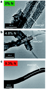 | ||
| Fig. 1 TEM images of ALD LiPON deposited on a MWCNT sponge with (a) 0% N, (b) 4.8% N, and (c) 9.3% N content. Both (a) and (b) are polycrystalline, while (c) is amorphous. The diameter of the MWCNTs was 30–40 nm.20 | ||
As illustrated in Fig. 1, ALD LiPON samples with less than 4.5% N were polycrystalline upon depositing on a multi-walled carbon nanotube (MWCNT) sponge.20 However, the crystalline morphology changed to an amorphous morphology when increasing the nitrogen content beyond 4.5% (see Fig. 1). They also showed that the ionic conductivity of the as-prepared ALD LiPON films increased with increasing nitrogen content (Fig. 2).20 However, the highest ionic conductivity (6.6 × 10⁻⁷ S cm−1) among the as-prepared samples was achieved at room temperature due to the high level of the N to P ratio doped within the thin film.
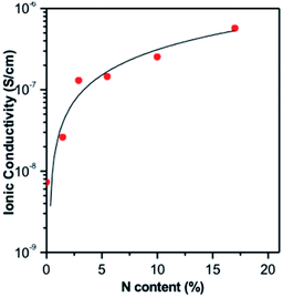 | ||
| Fig. 2 Ionic conductivity of ALD LiPON films plotted as a function of N content along with curve fit to the data.20 | ||
The Karppinen group in 2015 reported a novel way of synthesizing a Li0.99PO2.55N0.30 film using ALD at 330 °C with lithium hexamethyldisilazide LiN(SiMe3)2 (LiHMDS)–diethyl phosphorous-amidate H2NP(O)(OC2H5)2 (DEPA) (precursor–reactant).21 They demonstrated a homogeneous film grown in a controlled manner by the number of ALD cycles having a relatively high GPC (∼0.7 Å per cycle) within the temperature range of 270–310 °C, as depicted in Fig. 3. The deposited LiPON film at 330 °C exhibited a high ionic conductivity (6.6 × 10⁻⁷ S cm−1) measured at 25 °C.21 Later, they adopted the same precursor–reactant pair (LiHMDS–DEPA) to deposit a LiPON electrolyte by ALD and prepared Li-terephthalate (LiTP) hybrid electrodes for lithium ion batteries.22 They achieved a conformal coating of ∼40 nm in thickness and demonstrated 97% capacity retention (after 200 cycles at 3.2C) with the as-prepared hybrid electrodes (see Fig. 4).22 After extended cycling experiments (>500 cycles) at an ultra-high C-rate (6.4C), the capacity retention was 81% confirming superior cycling stability with the ALD-prepared LiPON electrolyte.22
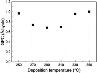 | ||
| Fig. 3 GPC for the ALD process of LiHMDS–DEPA as a function of deposition temperature. The number of ALD cycles was fixed at 1200. The pulse and purge lengths for both precursors were 2 s.21 | ||
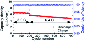 | ||
| Fig. 4 Cycle life of LiPON-coated LiTP measured at high rates of 3.2 and 6.4C.22 | ||
To further explore the efficacy of LiPON electrolytes for LIBs, Lin et al. demonstrated the critical role of a solid-state LiPON electrolyte as a nanocladding layer protecting the 3D-structure of the electrode from side reactions. thus enhancing cyclability (see Table 2), as illustrated in Fig. 5(a and b). According to Fig. 5(a), depositing a LiPON layer (SSE) via ALD on a MWCNT@RuO2 (electrode) structure significantly enhanced the capacity retention (>95%) compared to the bare MWCNT@RuO2 electrodes. Compared to the bare MWCNT@RuO2 electrode that usually experiences severe volume expansion during cycling,23 the implementation of LiPON nanocoating significantly improved the cyclability for two major reasons: (i) the LiPON layer enhanced the Li ion conductivity at the interface between the electrolyte and the electrode; (ii) it serves as an efficient protective layer constraining the electrode microstructure and subsequently preventing severe mechanical deformation during a lithiation/delithiation process over extended cycling.23
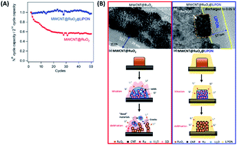 | ||
| Fig. 5 (A) Normalized capacities (capacity retention) of MWCNT@RuO2vs. MWCNT@RuO2@LiPON (all gravimetric capacities are normalized to the mass of RuO2) and (B) high-magnification transmission electron microscopy images of (a) 3D MWCNT@RuO2 electrodes (no protection) and (b) LiPON-protected MWCNT@RuO2 electrodes, discharged to 0.05 V vs. Li/Li+. (c and d) Schematic diagram of the mechanisms comparing the (c) bare MWCNT@RuO2 electrode and (d) LiPON-protected MWCNT@RuO2 to demonstrate the effect of the LiPON cladding layer, which enhances the mechanical stability and electron transport pathways.23 | ||
In another pioneering study, Gregorczyk et al. carried out thermal ALD using lithium tert-butoxide (LiOtBu) and DEPA precursors and were able to successfully synthesize LiPON (N/P ratio: 1).24 In contrast to previous reports, they demonstrated a possible polymorph phase and achieved a conformal thin film (stoichiometrically close to Li2PO2N) with an ionic conductivity of ∼6.51 × 10⁻⁷ S cm−1 at 35 °C.24 The film was deposited with a linear GPC ranging from ca. 0.15 (200 °C) to 0.9 Å per cycle (300 °C) and exhibited an exceptional electrochemical stability within the potential window of 0–5.3 V versus Li/Li+.24 The same group assembled 3D thin-film solid-state batteries (3D TSSB) with a LiV2O5 cathode and SnNx anode and achieved a specific capacity of 37 μA h cm−2 μm (normalized to the cathode thickness) with only 0.02% per-cycle capacity loss. It is important to note that the 3D structured TSSB enhanced the rate performance along with the round-trip efficiency and increased the areal capacity, simultaneously.25 From the above comparison, the most important conclusion is to maximize Li ion mobility in the LiPON electrolyte, which depends on accommodation N in bridging sites while keeping a high amount of charge carrier. It means that the concentration of Li according to LiPO4 and outlying O ions should be minimized. Based on these critical observations, the influence of the ALD parameters on the chemical composition, film thickness, internal structure as well as the electrolyte conductivity can be established.
Adopting ALD technique, SSEs with extremely thin film thickness (∼ few hundred nanometers) can be prepared for ultra-compact LIBs. Also, it should be noted that ALD of LiPON electrolytes is relatively difficult since they need Li containing cathodes (i.e., two-element operation) that is cumbersome to accomplish for a typical 3D SSE battery architecture. To ease the operation of ALD-LiPON electrolytes, further research must be dedicated for developing multi-element ALD setups using series of different precursors. These type of ALD systems can also significantly reduce the ALD cycle time due to employing various precursors simultaneously.
2.2. Garnet-type SSEs
Garnet-type materials are very promising solid state electrolytes for LIBs thanks to their remarkable properties including superior energy density, electrochemical stability, high-temperature stability, and safety. The general formula of garnet-type electrolytes is A3B2(XO4)3, where A and B represents crystallographic cationic co-ordination environment with X cation.To date, several high-performance garnet-type electrolytes have been synthesized, including Li5La3Ta2O12, Li5La3Nb2O12, Li7La3Sn2O12, Li5Nd3Sb2O12, and Li3Ln3Te2O12, with the ionic conductivities measured within the range of 10−6 to 10−4 S cm−1 at ambient temperature.9 Dasgupta et al. employed the thermal ALD technique to synthesize garnet-type Al-doped Li7La3Zr2O12 (LLZO) SSEs.26 The ALD deposited Al-doped LLZO films demonstrated high purity, tunable composition, and self-limiting behavior, as shown in Fig. 6. They also conducted a post-annealing treatment on different substrates to form a cubic-phase (c-LLZO) at 555 °C from its primary tetragonal-phase (t-LLZO) at room temperature.26 Through their comprehensive analysis, they concluded that thermal ALD is a very efficient technique for depositing ultrathin films with superior ionic conductivity and electrochemical stability enabling conformal coating of SSE/electrode interfaces for solid-state batteries.26
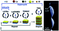 | ||
| Fig. 6 Schematic representation of an ALD supercycle for the growth of Al-doped LLZO films and the corresponding TEM micrograph.26 | ||
It was also demonstrated that the wettability along with the interfacial resistance of garnet-like Li7La2.75Ca0.25Zr1.75Nb0.25O12 (LLCZN) SSEs can be significantly enhanced via coating an Al2O3 layer (see Table 3).27 The wettability and stability of LLCZN were dramatically improved (Fig. 7(a and b)) leading to a significant decrease in interfacial resistance from 1710 to 34 Ω cm2 (see Fig. 7(c)). The decreased interfacial resistance was ascribed to three major reasons: (i) conformal ALD coating enabled a more efficient contact between the Li metal and the garnet-like SSE, (ii) the ALD coated Al2O3 layer provided a highly conductive pathway for Li ions transferring between the garnet and Li metal anode, and (iii) the implementation of the protective Al2O3 layer inhibited the impurity growth and improved the mechanical stability during lithium intercalation/deintercalation.27 The authors also conducted long-duration cycling experiments and confirmed the effect of the ALD-coated Al2O3 layer on enhancing cycling stability (see Fig. 7(d)).27
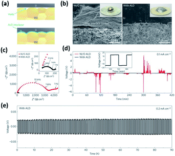 | ||
| Fig. 7 Characterization of a garnet-type SSE/Li metal interface. (a) Schematic of the wetting behavior of the garnet surface with molten Li. (b) Scanning electron microscopy (SEM) images of the garnet-type SSE/Li metal interface. Without ALD-Al2O3 coating, the SSE has a poor interfacial contact with Li metal even on heating. With the help of ALD-Al2O3 coating on garnet, Li metal can uniformly bond with the SSE at the interface on heating. The inset shows the photos of melted Li metal on top of the garnet surface clearly demonstrating classical wetting behavior for the ALD-treated garnet-type SSE surface. (c) Comparison of Nyquist plots of the symmetric Li non-blocking garnet cells. The inset shows the enlarged impedance curve of the ALD-treated cell. (d) Comparison of dc cycling for symmetric cells at 0.1 mA cm−2. The inset shows the magnified curve of the ALD-treated cell. (e) Cell voltage profile during extended cycling.27 | ||
In a following study, a similar approach was adopted and the wettability of a garnet-type SSE surface was significantly improved and an intimate contact between the Li metal and SSEs was achieved using an interfacial layer of ALD ZnO coating (see Fig. 8). It was shown that the ALD-coated ZnO layer substantially decreases the interfacial resistance (the interfacial impedance reached as low as 20 Ω cm2).28 Therefore, adopting ALD for nanocoating protective yet conductive layers on garnet-type electrolytes can hugely improve the wettability as well as the mechanical stability during lithium intercalation/deintercalation processes.
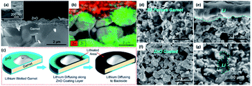 | ||
| Fig. 8 Characterization of ALD ZnO coating to improve the surface wettability of garnet-type SSEs with molten lithium. Cross-sectional (a) SEM images and (b) elemental mapping of the garnet electrolyte coated with a 50 nm ALD ZnO layer. The inset of (a) shows a cross-sectional SEM image of the SSE/ZnO interface at higher magnification. (c) Schematic of the lithium diffusion process along the ZnO coating layer on the SSE surface. The cross-sectional SEM images of (d) the pristine and (e) the lithium infiltrated porous SSE with a porosity of 60–70%. (f) The cross-sectional SEM image of the porous garnet coated with a conformal ZnO surface layer using the ALD process. (g) The cross-sectional SEM images of a lithium infiltrated porous SSE with ZnO surface treatment, where almost all pores have been filled with Li metal. The Li metal area has been marked with a cyan dashed line.28 | ||
2.3. Oxide-type SSEs
One of the pioneering studies on implementing ALD to prepare lithium tantalate thin films at low temperature (225 °C) was reported by the Sun group in 2003.29 They demonstrated a lithium tantalate thin film as a stable and conductive coating layer with relatively high conductivity (10−8 to 10−5 S cm−1) at room temperature.29 Lithium tert-butoxide (LiOtBu)–H2O–tantalum(V) ethoxide (Ta(OEt)5)–H2O was used as a precursor in a series of sequential pulses.29 The Sun group concluded that the GPC of the deposited film strongly depended on the number of Ta2O5 subcycles (i.e., 2.2, 5.2, and 7.3 Å per cycle) conducted during a complete ALD cycle (1 × Li2O + n × Ta2O5, where n is equal to 1, 6, and 10, respectively) as illustrated in Fig. 9.29 The deposited oxide layer demonstrated a well-controlled film thickness, conformal composition, excellent step coverage, and acceptable ionic conductivity (2 × 10⁻⁸ S cm−1) at room temperature.29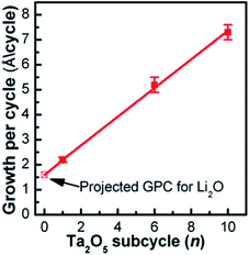 | ||
| Fig. 9 The GPC of the lithium tantalate thin films as a function of Ta2O5 subcycle number, using pulsing sequences of 1 × Li2O + n × Ta2O5 (n = 1, 6, and 10).29 | ||
In a subsequent study, the same group use the ALD method to modify a lithium tantalate thin film (electrolyte) on LiNi1/3Mn1/3Co1/3O2 (NMC) electrodes. The ALD-coated NMC cathodes showed outstanding electrochemical performance even under high voltage operating conditions.30 It is important to note that the electrochemical performance of the ALD-coated NMC cathodes was greatly influenced by the thickness of the nanocoated layer as well as the operating conditions. They considered five different cathode configurations labeled NMC-0, NMC-2, NMC-5, NMC-10, and NMC-20 based on the number of ALD cycles (i.e., 0, 2, 5, 10, and 20, respectively) and concluded that the NMC-5 cathode outperformed the other cathode configurations under various cycling conditions, whereas NCM-10 exhibited superior cyclability, high discharge capacity (122 mA h g−1), and remarkable capacity retention for high voltage operation (3.0–4.8 V) as depicted in Fig. 10. These observations confirmed that an optimal coating thickness is required for maintaining the structural stability while minimizing the mass transport overpotential induced by the coated layer.30
 | ||
| Fig. 10 The comparison of the cycle performance of NMC-0, NMC-2, NMC-5, NMC-10, and NMC-20 electrodes at a current density of 160 mA g−1 at room temperature in the voltage range of (a) 3.0–4.5 V, (b) 3.0–4.6 V, (c) 3.0–4.7 V, and (d) 3.0–4.8 V.30 | ||
Later, Comstock and Elam conducted ALD for coating an Al layer as a replacement for Ta to form lithium aluminum oxide (LiAlOx).31 They used trimethylaluminum (Al2O3)–H2O and lithium tert-butoxide (LiOH)–H2O as the precursor and found that the film composition can be finely tuned through modulating LiOH–H2O cycles.31 They also achieved a relatively high growth rate (i.e., 1.5 Å per cycle at ≤50% LiOH–H2O cycles) during the deposition process.31 Their observation revealed that a high percentage of Li cations within the ALD LiAlOx thin film was formed when LiOH cycles were >50%; however, a stable growth rate was maintainable only within 20–30 cycles.31 Furthermore, they were able to incorporate a high Li content within ALD-coated LiNbOx films via increasing the Li-to-Nb subcycle ratio (1![[thin space (1/6-em)]](https://www.rsc.org/images/entities/char_2009.gif) :
:![[thin space (1/6-em)]](https://www.rsc.org/images/entities/char_2009.gif) 1, 1
1, 1![[thin space (1/6-em)]](https://www.rsc.org/images/entities/char_2009.gif) :
:![[thin space (1/6-em)]](https://www.rsc.org/images/entities/char_2009.gif) 2, 1
2, 1![[thin space (1/6-em)]](https://www.rsc.org/images/entities/char_2009.gif) :
:![[thin space (1/6-em)]](https://www.rsc.org/images/entities/char_2009.gif) 4, and 2
4, and 2![[thin space (1/6-em)]](https://www.rsc.org/images/entities/char_2009.gif) :
:![[thin space (1/6-em)]](https://www.rsc.org/images/entities/char_2009.gif) 1, having a GPC of 1.82, 2.05, 2.54, and 2.87 Å, respectively).32 They successfully conducted ALD of a LiNbOx thin film at 235 °C with a well-controlled composition, conformality, and thickness and achieved a relatively high ionic conductivity (6 × 10⁻⁸ S cm−1) at room temperature for the ALD-coated LiNbOx sample prepared with a Li/Nb subcycle ratio of 1
1, having a GPC of 1.82, 2.05, 2.54, and 2.87 Å, respectively).32 They successfully conducted ALD of a LiNbOx thin film at 235 °C with a well-controlled composition, conformality, and thickness and achieved a relatively high ionic conductivity (6 × 10⁻⁸ S cm−1) at room temperature for the ALD-coated LiNbOx sample prepared with a Li/Nb subcycle ratio of 1![[thin space (1/6-em)]](https://www.rsc.org/images/entities/char_2009.gif) :
:![[thin space (1/6-em)]](https://www.rsc.org/images/entities/char_2009.gif) 4.32 As shown in Fig. 11, the thin film was examined by X-ray absorption near edge structure (XANES) spectroscopy and an amorphous morphology was confirmed with coexisting Nb and Nb5+ in a distorted octahedral structure.32
4.32 As shown in Fig. 11, the thin film was examined by X-ray absorption near edge structure (XANES) spectroscopy and an amorphous morphology was confirmed with coexisting Nb and Nb5+ in a distorted octahedral structure.32
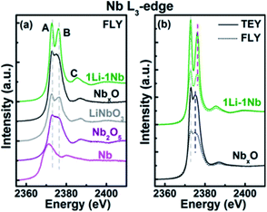 | ||
| Fig. 11 Nb L3-edge XANES spectra: (a) fluorescence yield (FLY) XANES spectra of ALD thin films and standard powders (LiNbO3, Nb2O5, and Nb) and (b) total electron yield and FLY XANES spectra of 1Li–1Nb and NbxO thin films.32 | ||
In another pioneering study, the Sun group reported ALD of lithium silicate (LixSiO, LSO) at different temperatures.33 They reported linear growth rates of 0.80, 1.00, 1.26, and 1.36 Å per cycle at 225, 250, 275, and 300 °C, respectively.33 They combined ALD Li2O and SiO2 subcycles and demonstrated ALD-coated thin films with a uniform composition and self-limiting growth in the temperature range of 225–300 °C. They observed that the Li2O subcycle facilitates the growth of a SiO2 layer and concluded that the ratio of Li to Si within the as-prepared thin films is maintained close to the stoichiometry of Li4SiO4 according to the X-ray photoelectron spectroscopy (XPS) analysis (see Fig. 12).33 The Sun group also reported that the lithium silicate at 250 °C exhibits a relatively high Li+ ion conductivity (1.45 × 10⁻⁶ S cm−1 at 30 °C), and upon doping Al into lithium silicate (LixAlySizO (LASO)), the conductivity substantially decreases (∼10−9 to 10−7 S cm−1) with apparent activation energy in the range of 0.46–0.84 eV, depending on the chemical composition of the films.33 The subsequent electrochemical measurement confirmed the presence of conformal and pinhole-free deposited thin films (thickness: 6–10 nm).34
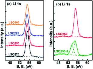 | ||
| Fig. 12 Deconvolution of Li 1s XPS spectra of lithium silicate thin films deposited (a) at different temperatures and (b) with different Li subcycle numbers.33 | ||
2.4. Perovskite-type SSEs
The perovskites-type SSEs of general formula ABO3 are high-performance solid-state materials with superior electrochemical stability.35 As one of the most promising lithium ion-conducting SSEs, lithium lanthanum titanate perovskite ceramics or Li3xLa(2/3)−xTiO3 (LLTO) have experienced a surge in attention due to their remarkably high bulk ionic conductivity (∼10−3 S cm−1, comparable to that of polymer/liquid electrolytes) and wide voltage stability window at room temperature.35 The high conductivity of LLTO could be elaborated by considering the LLTO structure; Li+ and La3+ are uniformly distributed within A sites in the cubic phase and orderly arranged in a doubled perovskite structure that causes slight tilting of octahedra. Therefore, at low-temperature operation, the mobility of Li ions within the 2D structure (i.e. a and b) is relatively fast while the vibration of oxygen atoms in these type of morphologies slows down the transport in c-direction.35In 2010, Aaltonen and co-worker reported on synthesizing Li0.32La0.30TiOz (LLT) thin films using the ALD technique with TiO2, La2O3, and Li2O (or LiOH) subcycles at 225 °C. The as-deposited thin films were converted from an amorphous to a crystalline structure (as confirmed by X-ray diffraction (XRD)) through implementing a post-annealing step in an oxygen environment at 800 °C (see Fig. 13).36 However, the as-grown films were unstable against low-voltage anode materials. To overcome this limitation, adopting the ALD technique, they have modified an interfacial layer of Li2O–Al2O3, between the LLT and anode material.37 They were able to successfully coat a Li2O–Al2O3 protective layer through combining multiple ALD substeps including lithium oxide/hydroxide and aluminum oxide processes. From the above recent research, it is realised that the ALD method is a very potential method for the preparation of multi-element SSEs through ALD subcycles. In addition, an ALD-coated thin film can serve as a protective layer stabilizing the anode material.
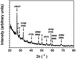 | ||
| Fig. 13 Grazing incidence XRD pattern of an about 100 nm-thick LLT film annealed in oxygen at 800 °C for 3 h.36 | ||
2.5. Sulphide-type SSEs
Solid-state sulphide-based electrolytes have several unique properties including a high ionic conductivity (10−4 to 10−2 S cm−1), wide electrochemical stability window, and favorable mechanical properties (e.g., formability). The high ionic conductivity was mainly attributed to the following two factors: (i) reduced grain boundary resistance and (ii) minimised void.38 Despite these unique attributes, the sulphide-based SSEs commonly suffer from severe issues such as poor cycle life and low performance/cyclability primarily due to high interfacial resistance between the SSE and the electrode.38,39 To reduce interfacial impedance, Elam et al. used the ALD technique for decorating ultrathin lithium aluminium sulphide (LixAlxS) thin films on Li metal anodes.40 LixAlxS ALD was carried out following the ALD procedure previously developed for coating Li2S films using (LiOtBu)–H2S (reactant–precursor pair)41 along with Al2S3 ALD based on tris(dimethylamido)aluminum(III) (TMDA-Al) and H2S on Li metal. Indeed, the atomic layer deposition of LixAlxS is controlled by the ALD cycles of Li2S and Al2S3 as schematically shown in Fig. 14(a) wwhere the deposited film is composed of Li2S/Al2S3 (1![[thin space (1/6-em)]](https://www.rsc.org/images/entities/char_2009.gif) :
:![[thin space (1/6-em)]](https://www.rsc.org/images/entities/char_2009.gif) 1 ratio). They also achieved a relatively high ionic conductivity (2.5 × 10⁻⁷ S cm−1) for the as-deposited films, as depicted in Fig. 14(b). The high ionic conductivity of the ALD deposited LixAlxS film, which not only stabilises at the electrolyte–Li electrode interface, but also highly suppresses Li dendrite growth. Additionally, they were able to reduce the interfacial impedance up to 5 fold approaching the contact resistance commonly observed for Li metal anodes with organic electrolytes (Fig. 14(c and d)).40
1 ratio). They also achieved a relatively high ionic conductivity (2.5 × 10⁻⁷ S cm−1) for the as-deposited films, as depicted in Fig. 14(b). The high ionic conductivity of the ALD deposited LixAlxS film, which not only stabilises at the electrolyte–Li electrode interface, but also highly suppresses Li dendrite growth. Additionally, they were able to reduce the interfacial impedance up to 5 fold approaching the contact resistance commonly observed for Li metal anodes with organic electrolytes (Fig. 14(c and d)).40
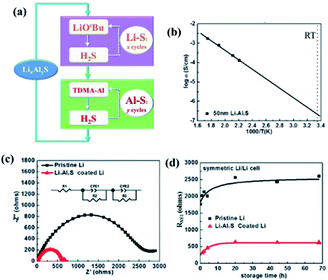 | ||
| Fig. 14 (a) Schematic illustration of LixAlyS ALD, (b) Arrhenius plot for temperature-dependent ionic conductivity measured using a 50 nm LixAlyS film, (c) AC impedance spectra of Li/electrolyte/Li symmetric cells using both pristine Li and LixAlyS-coated Li after 68 h storage, and (d) RSEI of Li/electrolyte/Li symmetric cells versus storage time.40 | ||
Although the contact impedance between the electrode and solid state sulphide-based electrolytes was significantly reduced through the ALD process, several major issues remained unresolved for achieving acceptable performance. Sulphide-based SSEs like Li10GeP2S12 (LGPS) commonly demonstrate severe instability with the LiNi0.8Co0.1Mn0.1O2 (NMC811) cathode during the charging process due to the formation of Li2S. Some prior studies have focused on improving the stability at the electrode/electrolyte interface. Sun and co-worker deposited a well-controlled and ultrathin film LiNbOx (LNO) on a NMC811 cathode via ALD and assembled with a LGPS electrolyte.42 This LNO layer assembled as an interfacial layer between the electrolyte and cathode. They reported that the deposited thin film stabilizes the interface, demonstrates high bulk ionic conductivity (2.07 × 10⁻³ S cm−1), and improves the electrochemical performance, as shown in Fig. 15(a–e). Given these significant improvements, it is clear that as-deposited LNO film on the NMC811 structure improves the ionic conductivity and suppresses the side reaction resulting in an enhanced electrochemical performance. Using the ALD technique, LNO was deposited with different controlled thicknesses. However, a thickness of 5 nm enabled better electrochemical properties.42 Hence, this ALD method is very helpful to synthesize ultrathin films with desired thickness for better LIB performance.
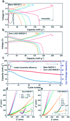 | ||
| Fig. 15 Electrochemical characterization of bare and LNO-coated NMC811 in LIBs. (a and b) Charge/discharge profiles, (c) cycling performance, and (d and e) EIS plots of batteries at various resting times and after the charge/discharge test.42 | ||
2.6. LBCO-type SSEs
Berzins et al. proposed a Li3BO3–Li2CO3 (LBCO) SSE in 1977 (ref. 43) and since then, its various structures including glassy and crystalline phases have been studied by several other groups.44–46 Recently, a relatively high conductivity (10−5 S cm−1) was reported for LBCO through adjusting Li and carbon contents within the Li3BO3–Li2CO3 microstructure.47 Despite having favorable attributes, synthesizing LBCO-type SSEs using the ALD technique has not been investigated thoroughly in the field. In one of the pioneering studies on the ALD of LBCO thin films, Dasgupta and co-worker performed LBCO ALD employing a 1![[thin space (1/6-em)]](https://www.rsc.org/images/entities/char_2009.gif) :
:![[thin space (1/6-em)]](https://www.rsc.org/images/entities/char_2009.gif) 1 ratio of LiOtBu–O3 subcycles to triisopropyl borate (TIB)–O3 subcycles (see Fig. 16(a)) and reported a linear GPC of 0.65 Å per cycle as measured by spectroscopic ellipsometry (see Fig. 16(b)).48 The deposited film was shown to be the result of a self-limiting reaction, where a linear growth rate was maintained over a range of deposition temperatures. The structure and properties of the deposited film were tuned by temperature and pre-treatment conditions.48 They also concluded that a consistent film growth can be preserved if the substrate temperature is kept within 200–260 °C.48
1 ratio of LiOtBu–O3 subcycles to triisopropyl borate (TIB)–O3 subcycles (see Fig. 16(a)) and reported a linear GPC of 0.65 Å per cycle as measured by spectroscopic ellipsometry (see Fig. 16(b)).48 The deposited film was shown to be the result of a self-limiting reaction, where a linear growth rate was maintained over a range of deposition temperatures. The structure and properties of the deposited film were tuned by temperature and pre-treatment conditions.48 They also concluded that a consistent film growth can be preserved if the substrate temperature is kept within 200–260 °C.48
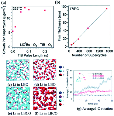 | ||
| Fig. 16 Characterization of ALD film growth with an in situ quartz crystal microbalance, showing (a) saturation of the growth rate with increasing TIB pulse time, and spectroscopic ellipsometry showing (b) linearly increasing film thickness with the number of supercycles. (c–f) Iso-surfaces of the ionic probability densities evaluated from ionic trajectories calculated over 60 ps AIMD at 500 K. (g) Average oxygen rotational displacements in borate and carbonate anions during AIMD. The iso-surfaces are plotted using an isosurface value of 2P0 (P0 represents the average probability density), for (c) Li in LBO, (d) O in LBO, (e) Li in LBCO, and (f) O in LBCO. (g) Averaged oxygen rotational displacements of LBO and LBCO during AIMD at 500 K.47 | ||
In a subsequent study, the same research group achieved a higher ionic conductivity (∼2.23 × 10⁻⁶ S cm−1 at 25 °C) via modulating the carbon to boron content in a mixture of Li2CO3 and Li3BO3 by following the ALD method.48,49 It was shown that the ionic conductivity of the deposited thin film is a strong function of the carbon content (Li2CO3 ratio) within the mixture.48,49 An increased Li2CO3 content resulted in increased Li+ mobility as demonstrated in Fig. 16(c–g). Moreover, the stability of the LBCO film against the Li anode was confirmed through in situ analysis of a cell stack assembled with ALD V2O5 (cathode)/ALD LBCO (SSE)/Li metal (anode) (see Fig. 17(a)).48,49 The ALD LBCO exhibited excellent cycling stability with the Li metal anode and delivered high coulombic efficiency for over 150 cycles with negligible capacity fading, as illustrated in Fig. 17(b).48,49 Therefore, the increased ionic conductivity and electrochemical performance indicate that the implementation of the ALD method is very advanced not only for the fabrication of ultrathin film SSEs, but also for forming interfacial or protective layers for the next generation of SSE batteries.
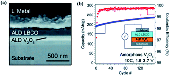 | ||
| Fig. 17 (a) SEM image of the FIB cross section of the full cell stack used in electrochemical measurements and (b) plot of discharge capacity and coulombic efficiency for the cell cycled at 10C.48,49 | ||
2.7. NASICON-types SSEs
Sodium super ionic conductors (NASICON) have found many applications as single-ion conductors in a variety of electrochemical devices. A very high ionic conductivity (∼0.1 mS cm−1) and exceptional structural stability are the major attributes of NASICON-type solid-state electrolytes. Among all NASICON-like SSEs, the Ti based one [LiTi2(PO4)3, or LTP] is a widely used Li+ ion conductor with a relatively high ionic conductivity compared to other tetravalent metal ions. However, to implement LTP as a solid-state electrolyte for high-performance LIBs, the ionic conductivity of this NASICON-type material must be improved. To this end, partially replacing Ti within the material structure through doping a larger size cation to from Li1.4Al0.4Ti1.6(PO4)3 (LATP) has been demonstrated to hugely improve the ionic conductivity (7 × 10⁻⁴ S cm−1). The improved ionic conductivity upon Al doping was majorly due to enhanced Li mobility as a result of Li–Li repulsion. Hence, the formation of vacancies at M1 sites enhances Li mobility.8,50 Despite having higher ionic conductivity, the structure of LATP becomes unstable when used in direct contact with a Li metal anode due to an unsteady phase formed at the interface of LATP/Li (in Li–O2 systems).51 For Li–S batteries, the implementation of LATP with a Li anode results in the formation of polysulphide reduced LATP, where the polysulphides deteriorate the performance of the LATP SSE.52 To enhance the performance of LATP in these structures, Sun et al. adopted the chemical-wet synthesis technique for preparing LATP and subsequently employed ALD to coat Al2O3 on the LATP SSEs.51 They used different ALD cycles (i.e., 25, 50, 100, 150, 200, and 250 cycles) and were able to prepare an interfacial layer on the LATP surface with various thicknesses (see Fig. 18(a–i)).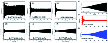 | ||
| Fig. 18 Electrochemical behavior of Al2O3ALD coated LATP/Li symmetrical cells after (a) 250, (b) 200, (c) 150, (d) 100, (e) 50, and (f) 25 cycles at a current density of 0.01 mA cm−2, where each cycle takes 2 h for lithium stripping and plating, (g) cycling behavior and voltage profile of bare LATP/Li in the 1st, 100th, 200th, and 300th cycles, (h) cycling behavior and voltage profile of LATP@150Al2O3/Li in the 1st, 100th, 200th, and 300th cycles, and (i) cycling behavior and voltage profile of LATP@175Li3PO4/Li in the 1st, 100th, 200th, and 300th cycles.51 | ||
They concluded that there is an optimum film thickness capable of improving the performance along with the stability and the reported LATP@150Al2O3 (i.e., ALD 150 cycles) sample as the best performing electrolyte compared to the other structures (ALD-treated and bare LATP).51 It is important to note that the LATP@150Al2O3 electrolyte demonstrated the lowest impedance during extended cycling and was more stable at the interface of LATP/Li anode due to the formation of a conductive layer (Li–Al–O) protecting the LATP structure.51
In a subsequent study, the same group adopt ALD to coat an interfacial layer of Al2O3 on LATP and designed a sandwich-type multi-layer barrier and employed polyethylene oxide (PEO) to coat both sides of LATP@ALD Al2O3.52 They analyzed the performance of sandwich-type SSEs (i.e., PEO/bare-LATP/PEO (PLP) and PEO/ALD Al2O3–LATP/PEO (ALD-PLP)) in a cell stack assembled with a sulphur electrode.52 The ALD coated PLP SSE demonstrated significant electrochemical performance (almost two time higher than that of PLP SSEs) with the initial discharge capacity reaching as high as 1035 mA h g−1, which gradually reduced to 823 mA h g−1 at the end of 100 cycles, as shown in Fig. 19(a).52 X-ray photoelectron spectroscopy (XPS) study revealed that the ALD coating prevents the reduction of Ti by polysulphides within the LATP structure (see Fig. 19(b)).52 According to Fig. 19, the XPS spectra associated with the bare LATP sample included a strong Ti 1s peak related to reduced-Ti and a weak peak ascribed to Ti4+ at the end of cycling, whereas the XPS spectra of the ALD-LATP sample did not include these strong peaks.52 This finding revealed that the ALD coating is very effective in protecting the LATP structure while preventing the reduction of Ti.52 Using ALD, the introduction of an interfacial layer of Al2O3 improves ionic conductivity, durability, and cycle performance, and reduce interfacial resistance between the electrolyte and electrode. This interfacial layer not only prevents the release of polysulfide, but also reduces the side reactions between the polysulfide and oxides within the SSE structure lessening the resistance.
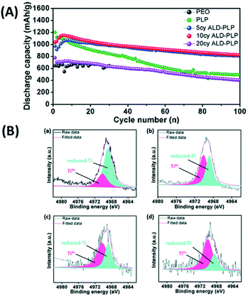 | ||
| Fig. 19 (A) Cycling performance of Li–S batteries with different electrolytes, where cell cycling was performed at a current density of 0.1C (1C = 1670 mA h g−1) and 60 °C. (B) Ti 1s XPS of (a) bare LATP, (b) 5 cycles of ALD-LATP, (c) 10 cycles of ALD-LATP and (d) 20 cycles of ALD-LATP after 100 charge/discharge cycles. All XPS studies were conducted on the LATP surface facing the sulfur cathode.52 | ||
3. Summary and future prospects
In this review, we have highlighted the implementation of ALD for depositing a thin and conductive interlayer at the solid-electrolyte–electrode interface for the LIBs utilizing solid state electrolytes and Li metal anodes. Different classes of SSEs including LiPON-, garnet-, oxide-, perovskite-, sulphide-, LBCO-, and NASICON-type electrolytes have been discussed and prior pioneering ALD studies conducted for depositing conformal and conductive barriers for each category of SSEs have been summarized. In particular, we have focused on the interface between the electrode and solid electrolyte since the utilization of SSEs in direct contact with Li metal commonly results in the formation of an unstable solid-electrolyte interface. Thus, it is critical to protect the SSE structure for designing high energy density LIBs utilizing Li anodes.ALD can be implemented for depositing an interfacial layer with desired attributes (high durability and ionic conductivity) capable of protecting the SSE against Li anodes. In Fig. 20, we have compared the variation in ionic conductivity for different classes of SSEs. Given the bulk ionic conductivity measured for different SSEs (∼10−8 to 10−4 S cm−1, see Table 1), much work is still needed for designing high-conductivity solid electrolytes (target: ∼10−3 to 10−2 S cm−1) for next-generation LIBs. To enable high rate capability, a new design of SSEs (ionic conductivity: >10−3 S cm−1) with high durability and mechanical stability is required. We believe that the ALD technique can be adopted for synthesizing new types of SSEs as well as depositing a conductive thin interfacial layer with desired characteristics.
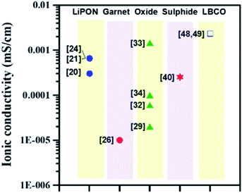 | ||
| Fig. 20 Variation of ionic conductivity at room temperature with different SSEs prepared by the ALD technique. | ||
Considering the unique properties of the ALD method, this technique can be used for synthesizing an emerging class of SSEs including lithium super ionic conductors (LISICONs). For example, LixAlySz (6.42 × 10⁻⁴ S cm−1) and Li1.4Al0.4Ti1.6(PO4)3 (2.94 × 10⁻⁴ S cm−1) are promising SSEs with high ionic conductivity and remarkable durability. To this end, selecting appropriate precursors and precisely controlling the ALD operating conditions (e.g., temperature, pressure, and subcycle sequence during a full ALD cycle) are critical. As summarized in Tables 1–3, only a limited number of precursors have been reported in prior ALD coating of SSEs. One interesting and relatively unexplored area is to elaborate on the doping process via ALD. To accomplish the desired doping procedure, the proportionalities of dopants must be finely tuned to finely tune the morphology and crystalline phase of SSE films and subsequently achieve high ionic conductivity. In addition, several dopant precursors need to be employed to fully explore the ALD doping chemistry. Indeed, designing an ALD system must be focused on enabling a precise control over the microstructure of the solid electrolytes. The SSEs prepared through ALD usually possess an amorphous or a mixture of amorphous and crystalline structures. Thus, a post-annealing treatment must be conducted for achieving desired microstructures.
Finally, the implementation of ALD for depositing thin and conductive films on SSEs should not be limited for lithium ion battery applications. Indeed, the ALD technique can be tuned for coating conductive interlayers with desired attributes within solid-electrolyte–electrode interfaces for other electrochemical devices (e.g., Li–air, Li–S, Li metal, and hybrid flow batteries) utilizing Li metal anodes and solid-state electrolytes. Although the details provided in this work were solely focused on batch-type ALD systems, the insights gained through this review can be applied for designing roll-to-roll ALD apparatus enabling continuous and large-scale production.
Conflicts of interest
There are no conflicts to declare.Acknowledgements
The authors are very grateful for the support from the Ministry of Science and Technology (Taiwan, ROC) under the contract (MOST 108-2221-E-155-036-MY3).References
- A. Vlad, N. Singh, C. Galande and P. M. Ajayan, Adv. Energy Mater., 2015, 5, 1402115 CrossRef.
- R. Giridharagopal, P. A. Cox and D. S. Ginger, Acc. Chem. Res., 2016, 49, 1769–1776 CrossRef CAS PubMed.
- L. Dai, Acc. Chem. Res., 2012, 46, 31–42 CrossRef PubMed.
- L. Ji, P. Meduri, V. Agubra, X. Xiao and M. Alcoutlabi, Adv. Energy Mater., 2016, 6, 1502159 CrossRef.
- B. Franklin and W. L. Leonard, The Papers of Benjamin Franklin, Yale University Press, New Haven, Connecticut, 1961, vol. 3, p. 352, Letter to Peter Collinson, April 29, 1749. Paragraph 18. Franklin Papers. Org. Retrieved 2012-08 Search PubMed.
- B. S. Finn, Origin of Electrical Power, National Museum of American History, September 2002, Retrieved 2012-08-29 Search PubMed.
- M. Du, K. Liao, Q. Lu and Z. Shao, Energy Environ. Sci., 2019, 12, 1780–1804 RSC.
- S. Chen, K. Wen, J. Fan, Y. Bando and D. Golbergce, J. Mater. Chem. A, 2018, 6, 11631–11663 RSC.
- L. Liang, X. Sun, J. Zhang, J. Sun, L. Hou, Y. Liu and C. Yuan, Mater. Horiz., 2019, 6, 871–910 RSC.
- M. Du, K. Liao, Q. Lu and Z. Shao, Energy Environ. Sci., 2019, 12, 1780–1804 RSC.
- E. Kazyak, K. H. Chen, K. N. Wood, A. L. Davis, T. Thompson, A. R. Bielinski, A. J. Sanchez, X. Wang, C. Wang, J. Sakamoto and N. P. Dasgupta, Chem. Mater., 2017, 29, 3785–3792 CrossRef CAS.
- C. Loho, R. Djenadic, M. Bruns, O. Clemens and H. Hahn, J. Electrochem. Soc., 2017, 164, A6131–A6139 CrossRef CAS.
- C. W. Ahn, J. J. Choi, J. Ryu, B. D. Hahn, J. W. Kim, W. H. Yoon, J. H. Choi and D. S. Park, J. Electrochem. Soc., 2015, 162, A60–A63 CrossRef CAS.
- S. Lobe, C. Dellen, M. Finsterbusch, H. G. Gehrke, D. Sebold, C. L. Tsai, S. Uhlenbruck and O. Guillon, J. Power Sources, 2016, 307, 684–689 CrossRef CAS.
- X. Huang, Y. Lu, J. Jin, S. Gu, T. Xiu, Z. Song, M. E. Badding and Z. Wen, ACS Appl. Mater. Interfaces, 2018, 10, 17147–17155 CrossRef CAS PubMed.
- B. C. Mallick, C. T. Hsieh, K. M. Yin, Y. A. Gandomi and K. T. Huang, ECS J. Solid State Sci. Technol., 2019, 8, N55–N78 CrossRef CAS.
- B. C. Mallick, C. T. Hsieh, K. M. Yin, J. Li and Y. A. Gandomi, Nanoscale, 2019, 11, 7833–7838 RSC.
- S. Gu, C. T. Hsieh, B. C. Mallick, Y. A. Gandomi, J. K. Chang, J. Li and P. K. Liaw, J. Mater. Chem. C, 2020, 8, 700–705 RSC.
- K. Senevirathne, C. S. Day, M. D. Gross, A. Lachgar and N. A. W. Holzwarth, Solid State Ionics, 2013, 233, 95–101 CrossRef CAS.
- A. C. Kozen, A. J. Pearse, C. F. Lin, M. Noked and G. W. Rubloff, Chem. Mater., 2015, 27, 5324–5331 CrossRef CAS.
- M. Nisula, Y. Shindo, H. Koga and M. Karppinen, Chem. Mater., 2015, 27, 6987–6993 CrossRef CAS.
- M. Nisula and M. Karppinen, Nano Lett., 2016, 16, 1276–1281 CrossRef CAS PubMed.
- C. F. Lin, M. Noked, A. C. Kozen, C. Liu, O. Zhao, K. Gregorczyk, L. Hu, S. B. Lee and G. W. Rubloff, ACS Nano, 2016, 10, 2693–2701 CrossRef CAS PubMed.
- A. J. Pearse, T. E. Schmitt, E. J. Fuller, F. El-Gabaly, C. F. Lin, K. Gerasopoulos, A. C. Kozen, A. A. Talin, G. Rubloff and K. E. Gregorczyk, Chem. Mater., 2017, 29, 3740–3753 CrossRef CAS.
- A. Pearse, T. Schmitt, E. Sahadeo, D. M. Stewart, A. Kozen, K. Gerasopoulos, A. A. Talin, S. B. Lee, G. W. Rubloff and K. E. Gregorczyk, ACS Nano, 2018, 12, 4286–4294 CrossRef CAS PubMed.
- E. Kazyak, K. H. Chen, K. N. Wood, A. L. Davis, T. Thompson, A. R. Bielinski, A. J. Sanchez, X. Wang, C. Wang, J. Sakamoto and N. P. Dasgupta, Chem. Mater., 2017, 29, 3785–3792 CrossRef CAS.
- X. Han, Y. Gong, K. K. Fu, X. He, G. T. Hitz, J. Dai, A. Pearse, B. Liu, H. Wang, G. Rubloff and Y. Mo, Nat. Mater., 2017, 16, 572–579 CrossRef CAS PubMed.
- C. Wang, Y. Gong, B. Liu, K. Fu, Y. Yao, E. Hitz, Y. Li, J. Dai, S. Xu, W. Luo and E. D. Wachsman, Nano Lett., 2017, 17, 565–571 CrossRef CAS PubMed.
- J. Liu, M. N. Banis, X. Li, A. Lushington, M. Cai, R. Li, T. K. Sham and X. Sun, J. Phys. Chem. C, 2013, 117, 20260–20267 CrossRef CAS.
- X. Li, J. Liu, M. N. Banis, A. Lushington, R. Li, M. Cai and X. Sun, Energy Environ. Sci., 2014, 7, 768–778 RSC.
- D. J. Comstock and J. W. Elam, J. Phys. Chem. C, 2013, 117, 1677–1683 CrossRef CAS.
- B. Wang, Y. Zhao, M. N. Banis, Q. Sun, K. R. Adair, R. Li, T. K. Sham and X. Sun, ACS Appl. Mater. Interfaces, 2018, 10, 1654–1661 CrossRef CAS PubMed.
- B. Wang, J. Liu, M. Norouzi Banis, Q. Sun, Y. Zhao, R. Li, T. K. Sham and X. Sun, ACS Appl. Mater. Interfaces, 2017, 9, 31786–31793 CrossRef CAS PubMed.
- Y. C. Perng, J. Cho, S. Y. Sun, D. Membreno, N. Cirigliano, B. Dunn and J. P. Chang, J. Mater. Chem. A, 2014, 2, 9566–9573 RSC.
- O. Bohnke, Solid State Ionics, 2008, 179, 9–15 CrossRef CAS.
- T. Aaltonen, M. Alnes, O. Nilsen, L. Costelle and H. Fjellvåg, J. Mater. Chem., 2010, 20, 2877–2881 RSC.
- T. Aaltonen, O. Nilsen, A. Magrasó and H. Fjellvag, Chem. Mater., 2011, 23, 4669–4675 CrossRef CAS.
- B. Wu, S. Wang, W. J. Evans IV, D. Z. Deng, J. Yang and J. Xiao, J. Mater. Chem. A, 2016, 40, 15266–15280 RSC.
- Z. Liu, W. Fu, E. A. Payzant, X. Yu, Z. Wu, N. J. Dudney, J. Kiggans, K. Hong, A. J. Rondinone and C. Liang, J. Am. Chem. Soc., 2013, 135, 975–978 CrossRef CAS PubMed.
- Y. Cao, X. Meng and J. W. Elam, ChemElectroChem, 2016, 3, 858–863 CrossRef CAS.
- X. Meng, D. J. Comstock, T. T. Fister and J. W. Elam, ACS Nano, 2014, 8, 10963–10972 CrossRef CAS PubMed.
- X. Li, Z. Ren, M. Norouzi Banis, S. Deng, Y. Zhao, Q. Sun, C. Wang, X. Yang, W. Li, J. Liang and X. Li, ACS Energy Lett., 2019, 4, 2480–2488 CrossRef CAS.
- R. D. Shannon, B. E. Taylor, A. D. English and T. Berzins, New Li solid electrolytes, in International Symposium on Solid Ionic and Ionic-Electronic Conductors, 1977, pp. 783–796 Search PubMed.
- E. E. Horopanitis, G. Perentzis, A. Beck, L. Guczi, G. Peto and L. Papadimitriou, J. Non-Cryst. Solids, 2008, 354, 374–379 CrossRef CAS.
- T. Okumura, T. Takeuchi and H. Kobayashi, Solid State Ionics, 2016, 288, 248–252 CrossRef CAS.
- K. Nagao, A. Hayashi and M. Tatsumisago, J. Ceram. Soc. Jpn., 2016, 124, 915–919 CrossRef CAS.
- F. Berkemeier, M. R. S. Abouzari and G. Schmitz, Phys. Rev. B: Condens. Matter Mater. Phys., 2007, 76, 109 CrossRef.
- E. Kazyak, K. H. Chen, A. L. Davis, S. Yu, A. J. Sanchez, J. Lasso, A. R. Bielinski, T. Thompson, J. Sakamoto, D. J. Siegel and N. P. Dasgupta, J. Mater. Chem. A, 2018, 6, 19425–19437 RSC.
- N. P. Dasgupta and E. F. Kazyak, US Pat., 16/515, 2020, p. 562 Search PubMed.
- K. Arbi, J. M. Rojo and J. Sanz, J. Eur. Ceram. Soc., 2007, 27, 4215–4218 CrossRef CAS.
- Y. Liu, Q. Sun, Y. Zhao, B. Wang, P. Kaghazchi, K. R. Adair, R. Li, C. Zhang, J. Liu, L. Y. Kuo and Y. Hu, ACS Appl. Mater. Interfaces, 2018, 10, 31240–31248 CrossRef CAS PubMed.
- J. Liang, Q. Sun, Y. Zhao, Y. Sun, C. Wang, W. Li, M. Li, D. Wang, X. Li, Y. Liu and K. Adair, J. Mater. Chem. A, 2018, 6, 23712–23719 RSC.
Footnote |
| † Electronic supplementary information (ESI) available. See DOI: 10.1039/d0na01072c |
| This journal is © The Royal Society of Chemistry 2021 |
