 Open Access Article
An all-inorganic, fully dense, stretchable ceramic magnetic film†
Muchun
Liu
 *ab,
Lijuan
Qian
 c,
Chao
Yu
 a,
Gang
Xiao
 *c and
Robert H.
Hurt
 *a
*a
aSchool of Engineering, Brown University, Providence, RI 02912, USA. E-mail: robert_hurt@brown.edu
bDepartment of Civil and Environmental Engineering, Massachusetts Institute of Technology, Cambridge, MA 02139, USA. E-mail: muchunl@mit.edu
cDepartment of Physics, Brown University, Providence, RI 02912, USA. E-mail: gang_xiao@brown.edu
First published on 8th December 2020
Abstract
There is widespread interest in new materials-based approaches for introducing flexibility to electromagnetic devices, such as displays, human–machine interfaces, smart textiles, and biomedical implants. From fabrication to application, incorporating ceramic components is particularly challenging due to their extreme stiffness. Here, we introduce a new approach for designing flexible ceramic films and demonstrate it by fabricating fully dense, pre-wrinkled magnetic cobalt ferrite films composed of tiled nanoplatelets. The method relies on the colloidal engineering of metalized graphene nanosheets, which are cast and compressed into wrinkled composite films with accurate control of composition and morphology. Removal of the graphene template by thermal oxidation yields free-standing cobalt ferrite films that can be stretched up to 200% and bent to radii of 2.5 mm while maintaining their magnetic properties. Magnetization retention of 73% is documented after 150% linear mechanical stretching over 100 cycles. The significant stretchability and flexibility in this hard magnetic material is achieved at near full metal oxide crystal density without addition of significant void space or a polymeric elastomer matrix.
Introduction
Flexible and stretchable devices are becoming essential components in next-generation technologies that include electronic displays, soft robotics, electronic skins, smart textiles, batteries and supercapacitors for energy storage, and functional biomedical implants.1–4 Imparting flexibility and stretchability often pose significant materials science challenges and most approaches often fall in one of two classes: compositional design and structural design. Compositional design involves replacing rigid material components with flexible alternatives, such as conductive polymers, carbon nanotubes, and graphene-based materials.5–7 In contrast, the structural design approach retains the traditional focus on hard material components but manipulates their physical form and structure to allow device deformation, for example through thickness reduction (e.g. Ag nanowires, nanoribbons, flexible hard metal magnetic films), engineered wavy structures (e.g. buckled Si films) or open mesh geometries such as patterned arrays of metallic interconnects.2,8 Some functional materials, however, cannot be simply replaced or effectively re-shaped, and ceramics components are often particularly challenging due to extreme stiffness and brittleness.Ceramic materials that serve as semiconductors (In2O3/ZnO, SiC), insulators (Si3N4), catalysts (Al2O3, Fe2O3) or magnetic nanoparticles (CoFe2O4) can be essential in emerging devices3,9 Ceramics, however, typically fracture at low strain (typically 0.1–0.2%), which can pose a significant challenge for engineering flexibility and stretchability.10,11 For this reason, most ceramic components are incorporated in devices as nano/micro-scale dispersed phases encapsulated in soft matrices and or integrated through stretchable interconnects that accommodate the primary stress during deformation.12–15 The use of the flexible matrix results in lower loading of active material and diminished device performance and/or challenges in processing and the potential for interfacial failure.16,17
Here we propose and evaluate a concept for structural design of flexible and stretchable magnetic ceramic metal oxide films that do not involve an elastomeric matrix yet express full density of the inorganic active component. The concept is based on our previous work creating 1D, 2D and hierarchical wrinkle topographies in graphene-based films,18 and using them as sacrificial templates to self-assemble wrinkled films of other inorganic compositions.19 In this method, hybrid metal–graphene oxide (GO) nanosheets are colloidally engineered into stable inks that can be written onto substrates to form GO nanosheet films with high densities of metal ions confined in the 2D gallery spaces. In-plane compression of these metallized graphene films produces wrinkles, crumples or complex architectures18 that can be calcined to oxidize graphene and assemble tiled metal oxide films that retain the wrinkled microtexture. In the present study, we synthesized pre-wrinkled films of cobalt ferrite (CoFe2O4) – a ferrimagnetic ceramic – and characterized their flexibility, stretchability, and magnetic properties, as well as the stability of those magnetic properties during multiple flex/stretch cycles.
Experimental
Materials
Ethanol, iron(III) nitrate nonahydrate (Fe(NO3)3·9H2O), cobalt(II) nitrate hexahydrate (Co(NO3)2·6H2O), anhydrous acetone and methylene chloride were purchased from Sigma-Aldrich. GO was synthesized by a modified Hummers' method as reported before.20 Thermally responsive polystyrene heat shrink films were purchased from Grafix. Polydimethylsiloxane (PDMS) was made from a SYLGARD 184 silicone elastomer kit. All water was deionized (18.2 MΩ, milli-Q pore). All reagents were used as received without further purification.Procedures
![[thin space (1/6-em)]](https://www.rsc.org/images/entities/char_2009.gif) :
:![[thin space (1/6-em)]](https://www.rsc.org/images/entities/char_2009.gif) 1 weight ratio (base to curing agent). Here 1.75 g of the base/curing agent mixture was poured into an aluminum dish under vacuum for 15 minutes, then placed in a 60 °C oven for 14 minutes. When the PDMS was partially cured to a gel phase, a SMOF was gently placed on the surface of PDMS. The highly viscous PDMS gel conformally deformed along and supported the wrinkles of SMOF. The mixture was put back into 60 °C oven for another 20 minutes to stabilize the adhesion of PDMS and prevent the immersion of SMOF.
1 weight ratio (base to curing agent). Here 1.75 g of the base/curing agent mixture was poured into an aluminum dish under vacuum for 15 minutes, then placed in a 60 °C oven for 14 minutes. When the PDMS was partially cured to a gel phase, a SMOF was gently placed on the surface of PDMS. The highly viscous PDMS gel conformally deformed along and supported the wrinkles of SMOF. The mixture was put back into 60 °C oven for another 20 minutes to stabilize the adhesion of PDMS and prevent the immersion of SMOF.
Results and discussion
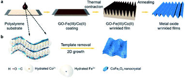
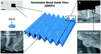
Fig. 1a illustrates the fabrication route for SMOF adapted from our previously reported method.19 Briefly, a GO–Fe(III)/Co(II) solution/suspension is drop cast onto thermally responsive polystyrene substrates. Heating actuates substrate contraction, and the resulting compression and periodic folding of the top film is restricted to one dimension by physical fixation of the substrate on two opposing ends. The wrinkled GO–Fe(III)/Co(II) coating is then calcined under 600 °C to remove the graphene template and release a free standing SMOF. Note that the GO nanosheets are used as sacrificial templates to create arrays of ultrathin 2D reaction chambers, but are not retained in the final product. The encapsulated metal ions originally confined in the 2D gallery spaces are converted to continuous tiled polycrystalline ceramic films by a self-assembly process that replicates the original graphene textures at high fidelity (Fig. 1b). X-ray diffraction (XRD) shows a single phase of Co2FeO4 (Fig. S2†). Thermogravimetric analysis (TGA) reveals the sequence of chemical events as the composite is heated, which begin with metal salt decomposition, then GO to reduced GO thermal conversion (partially overlapping with salt decomposition), and then a late removal of the graphene-like reduced GO through O2 reaction above 450 °C (Fig. S3†).Detailed morphologies of the SMOFs are shown in Fig. 2. In the free standing state, SMOFs exhibit the dark brown color of Co2FeO4 (Fig. 2a). On the microscale, SMOFs replicate the characteristic GO wrinkle texture – continuous out-of-plane undulations – in a unidirectional pattern with wavelength of ∼5 μm (Fig. 2 and S4†). Fig. 2b and c show an example cross-section of SMOFs, which contains ∼3 layers with each layer having a thickness ∼30 nm. The multi-layer structure of the SMOF likely arises from the layered structure of the GO template though the SMOF shows much smaller layer number indicating Z-directional consolidation during the complex decomposition and assembly process. The surfaces of the SMOF show tessellated nanoplatelets ∼150 nm in lateral size, arranged as in a mathematical tessellation (Fig. 2d). The constituent nanoplatelets are not isotropic nanoparticles, but have plate-like geometries and smooth top surfaces that reflect 2D crystal growth. From Fig. S5† we can see the primary crystal growth direction of the Co2FeO4 nanoplatelets is [011].
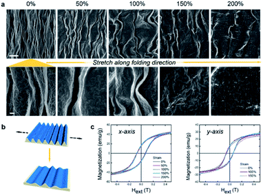
Fig. 3a shows the stretching behavior of the stretchable metal oxide films. We used a similar technique to our previous work on pure GO,22 in which crumpled GO films were attached to an elastomeric substrate and expanded to 1500% areal strain for 500 cycles. Here SMOFs were attached to the top of PDMS substrates and slowly stretched to strains of 50, 100, 150 and 200%. We observed no obvious cracks at or below 100% strain, which is remarkable since cobalt ferrite has no significant intrinsic elasticity on this scale. Micro cracks initiated on the ridges at 150% strain, then propagated at 200% (Fig. 3b). The wavelengths of wrinkles in samples increased from 5 (at 0% strain) to 10 (at 50%), 15 (at 100%), 25 (at 150%) and 35 μm (at 200% strain). In the simple case where all N wrinkles are preserved, the wavelength is ∼L/N (L as the total length) and should grow proportionally to L during stretching. The faster increase in wavelength observed in the present data may be explained by the heterogeneous nature of the wrinkles and the disappearance of secondary wrinkles at high strain leading to local doubling. The height of SMOF decreased from ∼6 μm to 150 nm (the thickness of planar metal oxide film) at 150% strain. We used a vibrating-sample magnetometer (VSM) to probe the magnetic properties of the films and their stress coupling (Fig. 3c). The saturation magnetization (Ms) and remnant magnetization (Mr) of SMOF along the x-axis (parallel to the wrinkles) are ∼50 and 15 emu per g, and remain stable under strains up to 200% at room temperature. The Ms along the y-axis (perpendicular to the wrinkles) shows a 10% increase at 150% strain, which may be caused by the restoration of the shape anisotropy in the SMOF. The Mr along x- or y-axis shows insignificant change during stretching (Fig. S6a and b†). No scaling of nanocrystals was observed upon stretching, and therefore, SMOF shows high stretchability and stable magnetic properties.
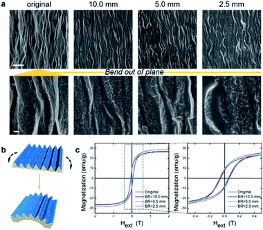
The flexibility of SMOFs was studied by again adhering the films on PDMS substrates and now wrapping the composite around aluminum columns with radii of 10.0, 5.0 and 2.5 mm. Fig. 4a shows that bending had little effect on SMOF surface morphologies, and SEM images revealed no cracks appearing as a result of the bend deformation. Over one wrinkle wavelength, the angle caused by bending is quite small (3 × 10⁻², 6 × 10⁻² or 0.1 degrees, at bending radii of 10.0, 5.0 or 2.5 mm) comparing with the local deformation angles built into the wrinkles (∼6 × 10 degrees). The high density of wrinkles on curved surfaces mitigates the stress concentration. Therefore, the microstructure of SMOF facilitates its adaptation to different types of macroscale mechanical deformation. The magnetic behaviors of SMOFs remain quite stable under bending strain (Fig. 4b and c). The Ms of SMOF is ∼30 emu per g irrespective of bending strain. The Mr along x-axis also remains stable during bending (Fig. S6c†).
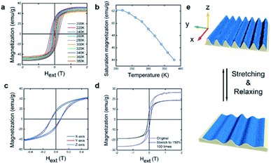
Fig. 5a and b shows the temperature dependence of SMOF magnetic properties. Increasing temperature from 200 to 380 K, causes a slight decrease in Ms from 52 to 44 emu per g, which is consistent with a previous report that the Curie temperature, Tc ∼ 800 K in Co2FeO4.23 The coercive field, Hc, is strongly dependent on temperature, decreasing 10 fold from 0.268 to 0.0265 T as temperature rises from 200 to 380 K. Both coercivity and remnant magnetization decrease with increasing temperature, indicating a decrease in anisotropy along the x-axis (parallel to wrinkles) due to the thermal energy. The directional dependence of the hysteresis was measured along the x-axis (parallel to wrinkles), y-axis (perpendicular to wrinkles) and z-axis (perpendicular to the film plane). The M vs. H relationships are similar along the three axes (Fig. 5c) but Mr is 20% larger along the x-axis than the y- and z-axes. In general, a random distribution of the magnetocrystalline anisotropy in each nanoplatelet leads to similar behavior along the x- and y-axes (both are stronger than z-axes).24 The wavy topography of the wrinkled films provides an undulate surface along the y-axes, which disturbs the shape anisotropy in the SMOF and results in slightly decreased Mr. Finally, a mechanical fatigue test was conducted by stretching a SMOF to 150% strain over 100 times. Comparison of magnetization is shown in Fig. 5d and e, the Ms decreased to 73% of original after fatigue.
Overall, the key concept in this study is to fabricate a fully dense, geometrically stretchable metal oxide film, in a simple templating method, to produce wrinkled ceramic magnetic film. The technique accomplishes a densely packed nanocrystal tessellation with outstanding mechanical behaviors. The stable magnetic performance of SMOFs during stretching or bending is promising in stretchability-oriented applications.2,25,26 However, potential correlation between mechanical strain and magnetic properties may be expected through future investigation including tuning of wrinkling wavelength, surface roughness or size/orientation of nanocrystals.24,27
Conclusions
Here we synthesized and characterized a stretchable, flexible, magnetic CoFe2O4 film without the use of polymer matrices by a 2D self-assembly method using textured graphene templating. The final films achieve high stretchability (200% strain) and flexibility (2.5 mm bending radius) while maintaining stable magnetic performance. The synthesis approach uses simple, scalable aqueous film casting technique and may be extendable to other hard magnetic materials. This work demonstrates a new and alternative approach for incorporating brittle ceramic components in flexible or stretchable devices being currently developed for wearable, implantable, skin-mounted, or hand-held technologies.Conflicts of interest
The authors have no conflicts to declare.Acknowledgements
The authors thank Prof. P. Y. Chen from University of Maryland, College Park for helpful discussions and acknowledge financial support from an OVPR Research Seed Award from Brown University.References
- S. Xu, Y. Zhang, J. Cho, J. Lee, X. Huang, L. Jia, J. A. Fan, Y. Su, J. Su, H. Zhang, H. Cheng, B. Lu, C. Yu, C. Chuang, T.-i. Kim, T. Song, K. Shigeta, S. Kang, C. Dagdeviren, I. Petrov, P. V. Braun, Y. Huang, U. Paik and J. A. Rogers, Nat. Commun., 2013, 4, 1543 CrossRef
.
- J. H. Koo, D. C. Kim, H. J. Shim, T.-H. Kim and D.-H. Kim, Adv. Funct. Mater., 2018, 28, 1801834 CrossRef
.
- W. A. D. M. Jayathilaka, K. Qi, Y. Qin, A. Chinnappan, W. Serrano-García, C. Baskar, H. Wang, J. He, S. Cui, S. W. Thomas and S. Ramakrishna, Adv. Mater., 2019, 31, 1805921 CrossRef
.
- M. Melzer, D. Makarov and O. G. Schmidt, J. Phys. D: Appl. Phys., 2019, 53, 083002 CrossRef
.
- J. Mun, J. Kang, Y. Zheng, S. Luo, H.-C. Wu, N. Matsuhisa, J. Xu, G.-J. N. Wang, Y. Yun, G. Xue, J. B. H. Tok and Z. Bao, Adv. Mater., 2019, 31, 1903912 CrossRef CAS
.
- T. Kim, M. Cho and K. J. Yu, Materials, 2018, 11, 1163 CrossRef
.
- H. Jang, Y. J. Park, X. Chen, T. Das, M.-S. Kim and J.-H. Ahn, Adv. Mater., 2016, 28, 4184–4202 CrossRef CAS
.
- D.-H. Kim and J. A. Rogers, Adv. Mater., 2008, 20, 4887–4892 CrossRef CAS
.
- J. A. Rogers, T. Someya and Y. Huang, Science, 2010, 327, 1603 CrossRef CAS
.
-
D. J. Green, An Introduction to the Mechanical Properties of Ceramics, Cambridge University Press, Cambridge, 1998 Search PubMed
.
- S. G. Seshadri and K. Y. Chila, J. Am. Ceram. Soc., 1987, 70, C-242–C-244 CrossRef
.
- K. Sim, Z. Rao, Z. Zou, F. Ershad, J. Lei, A. Thukral, J. Chen, Q.-A. Huang, J. Xiao and C. Yu, Sci. Adv., 2019, 5, eaav9653 CrossRef CAS
.
-
T. Koshi and E. Iwase, Stretchable Electronic Device with Repeat Self-Healing Ability of Metal Wire, 2017 IEEE 30th International Conference on Micro Electro Mechanical Systems (MEMS), 2017, pp. 262–265 Search PubMed
.
-
J. van den Brand, M. de Kok, A. Sridhar, M. Cauwe, R. Verplancke, F. Bossuyt, J. de Baets and J. Vanfleteren, Flexible and Stretchable Electronics for Wearable Healthcare, 2014 44th, European Solid State Device Research Conference (ESSDERC), 2014, pp. 206–209 Search PubMed
.
- N. Lazarus, C. D. Meyer, S. S. Bedair, G. A. Slipher and I. M. Kierzewski, ACS Appl. Mater. Interfaces, 2015, 7, 10080–10084 CrossRef CAS
.
-
Y. Iwata and E. Iwase, Stress-Free Stretchable Electronic Device Using Folding Deformation, 2017 IEEE 30th International Conference on Micro Electro Mechanical Systems (MEMS), 2017, pp. 231–234 Search PubMed
.
- S. Lee, Y. Song, Y. Ko, Y. Ko, J. Ko, C. H. Kwon, J. Huh, S.-W. Kim, B. Yeom and J. Cho, Adv. Mater., 2020, 32, 1906460 CrossRef CAS
.
- P.-Y. Chen, J. Sodhi, Y. Qiu, T. M. Valentin, R. S. Steinberg, Z. Wang, R. H. Hurt and I. Y. Wong, Adv. Mater., 2016, 28, 3564–3571 CrossRef CAS
.
- M. Liu, P.-Y. Chen and R. H. Hurt, Adv. Mater., 2018, 30, 1705080 CrossRef
.
- Y. Qiu, S. Moore, R. Hurt and I. Külaots, Carbon, 2017, 111, 651–657 CrossRef CAS
.
- F. Kim, J. Luo, R. Cruz-Silva, L. J. Cote, K. Sohn and J. Huang, Adv. Funct. Mater., 2010, 20, 2867–2873 CrossRef CAS
.
- P.-Y. Chen, M. Zhang, M. Liu, I. Y. Wong and R. H. Hurt, ACS Nano, 2018, 12, 234–244 CrossRef CAS
.
- D. S. Mathew and R.-S. Juang, Chem. Eng., 2007, 129, 51–65 CrossRef CAS
.
- M. T. Johnson, P. J. H. Bloemen, F. J. A. d. Broeder and J. J. d. Vries, Rep. Prog. Phys., 1996, 59, 1409–1458 CrossRef CAS
.
- B. Wang, A. Thukral, Z. Xie, L. Liu, X. Zhang, W. Huang, X. Yu, C. Yu, T. J. Marks and A. Facchetti, Nat. Commun., 2020, 11, 2405 CrossRef CAS
.
- F. Li, H. Zhao, Y. Yue, Z. Yang, Y. Zhang and L. Guo, ACS Nano, 2019, 13, 4191–4198 CrossRef CAS
.
- S. Monso, B. Rodmacq, S. Auffret, G. Casali, F. Fettar, B. Gilles, B. Dieny and P. Boyer, Appl. Phys. Lett., 2002, 80, 4157–4159 CrossRef CAS
.
Footnote |
| † Electronic supplementary information (ESI) available. See DOI: 10.1039/d0na00949k |
| This journal is © The Royal Society of Chemistry 2021 |

