 Open Access Article
Controllable self-patterning behaviours of flexible self-assembling peptide nanofibers†
Yongzhu
Chen
abc,
Feng
Qiu
 *ab,
Chengkang
Tang
bd,
Zhihua
Xing
be and
Xiaojun
Zhao
*b
aLaboratory of Anaesthesia and Critical Care Medicine, Translational Neuroscience Centre, National Clinical Research Center for Geriatrics, West China Hospital, Sichuan University, Chengdu 610041, China. E-mail: fengqiu@scu.edu.cn
bInstitute for Nanobiomedical Technology and Membrane Biology, West China Hospital, Sichuan University, Chengdu, 610041, China. E-mail: xiaojunz@mit.edu
cPeriodical Press of West China Hospital, Sichuan University, Chengdu 610041, China
dCore Facility of West China Hospital, Sichuan University, Chengdu, 610041, China
eLaboratory of Ethnopharmacology, West China School of Medicine, West China Hospital, Sichuan University, Chengdu, 610041, China
First published on 22nd January 2021
Abstract
In recent years, fabricating flexible one-dimensional nanofibers with a high aspect ratio and controlling their two-dimensional patterns on a certain surface have attracted more and more attention. Although molecular self-assembly as a useful strategy has been widely used to obtain nanofibers from soft materials such as peptides and polymers, extremely long nanofibers with high flexibility were rarely reported, and it's even more challenging to organize these organic nanofibers into ordered patterns in a controllable manner. In this study, we designed a flat-wedge-shaped bolaamphiphilic peptide which could self-assemble into ultra-flexible long nanofibers. These nanofibers were deposited on a mica surface by long-term incubation and exhibited various self-patterning behaviours as controlled by intended treatment. By changing the incubation time on the mica surface, vapour pH in the incubation device, and the peptide concentration, various patterns including nanofiber coils, parallel or single straight long nanofibers, and a network of hexagonally aligned short nanofibers could be obtained. These results indicated that not only the nanostructure formed by self-assembling peptides, but also the higher-order patterning behaviour of the nanostructures could be rationally controlled, providing a promising strategy for fabricating complicated nanoscale architectures with various potential applications.
Introduction
Fast-developing nanotechnology has brought forward the challenge of fabricating complex structures smaller and smaller to the scale of nanometers.1,2 In this field, flexible nanofibers which can be manipulated to form well-ordered patterns on a certain surface are of special interest because of their potential applications in fabricating nanodevices such as nanocircuits and wearable sensors.3,4 To date, nanofiber patterns formed from various types of materials including synthetic polymers, natural cellulose and inorganic carbon have been reported.5–7 Nearly all these nanofiber patterns were generated by using electrospinning technology, representing a traditional “top-down” strategy for the fabrication of complicated nanofiber patterns.In recent years, designer self-assembling peptide nanofibers (SAPNs) as a group of emerging nanomaterials have also attracted increasing attention.8–10 Unlike nanofibers obtained by electrospinning, SAPNs were formed by the self-assembly process of short peptides. This “bottom-up” strategy makes it possible to control the morphology of nanofibers by deliberate peptide design, generating nanofibers with a much smaller thickness of less than ten nanometers. Because of their perfect one-dimensional morphology and combinability with metal ions, some SAPNs have shown potential applications such as being templates for fabricating metallic nanowires.11–14
However, since peptide self-assembly is supported by weak non-covalent forces, it's difficult to obtain long SAPNs with considerable flexibility. As a spontaneous process, it's even more challenging to control the alignment of SAPNs to get well-ordered two-dimensional patterns. To the best of our knowledge, extremely long nanofibers with very high flexibility have not been obtained from any self-assembling peptide yet, and only a few SAPNs or nanotubes forming certain patterns have been reported.15–18 In order to further exploit the potential application of SAPNs for nanoscale fabrication, it would be of great advantage if we could control the patterning behaviour of SAPNs just as how we control the self-assembling behaviour of peptide monomers. However, this intriguing task still seems to be a tremendous challenge so far.
In our previous studies, we have proved that the self-assembly process of peptide monomers could be rationally controlled by deliberate peptide design, such as changing the charge distribution and geometrical shape of peptides.19–21 On the other hand, environmental parameters such as pH and solvent polarity could also affect the morphology of nanostructures and their alignment.21,22 These findings suggested that by deliberate peptide design and environment control, it's possible to fabricate desired nanostructures with controllable patterning behaviour. In this study we reported the formation of ultra-flexible long nanofibers from DGAV (abbreviation for the sequence of DGGAAVVD), a bolaamphiphilic peptide with a shape of a flat wedge, and showed how the nanofibers formed from it could self-organize into various two-dimensional patterns on a mica surface induced by intended treatments.
Experimental
Peptide synthesis and preparation
The peptide DGAV used in this study was commercially synthesized and purified (>95%) by Shanghai Bootech BioScience & Technology Co., Ltd. A native peptide sample was prepared by dissolving lyophilized peptide powder in sterile Milli-Q water to a concentration of 1.5 mM and the pH value was measured to be 2.0. Peptide solutions with pH values of 1.0, 5.0, 8.0, 10.0 and 12.0 were obtained by adjusting the pH of the native peptide solution with 0.1 M HCl or 0.1 M NaOH. All peptide solutions were stored at room temperature.Circular dichroism (CD)
Peptide samples with a pH value of 2.0, 5.0 or 8.0 were diluted to a concentration of 0.1 mM and immediately used for CD measurement. The far-ultraviolet CD spectra from 190 nm to 260 nm were collected by using a Model 400 Circular Dichroism Spectrophotometer (Aviv Biomedical, Inc.) with a wavelength step of 1 nm. For each sample, the CD spectrum was obtained as the calculated average of three collections and converted to molar ellipticity.Dynamic light scattering (DLS) and zeta potential
The size distribution of nanostructures formed in peptide solutions with different pH was measured by DLS using a Zetasizer Nano-ZS instrument (Malvern, UK). Briefly, each peptide solution (pH = 2.0, 5.0 or 8.0) was added into a ZEN0112-low volume disposable sizing cuvette and kept at 25 °C for 2 min prior to measurement. Intensity data were collected and size-versus-fraction distribution plots were obtained. The zeta potential of peptide solutions with different pH was also measured with an instrument using a disposable zeta potential cuvette. Each sample was measured three times to obtain an averaged zeta potential.Fourier transform infrared spectroscopy (FTIR)
To detect the formation of intermolecular hydrogen bonds, several drops of each peptide solution with different pH (2.0, 5.0 and 8.0) were added dropwise onto a zinc selenide substrate, air-dried and formed a layer of thin film. FTIR spectra between the wave numbers of 1500 and 2000 cm−1 were then collected with a Nicolet 6700 spectrometer (Thermo Scientific Inc., USA).Nuclear magnetic resonance (NMR)
DGAV was dissolved in a mixture of H2O and D2O (volume ratio 9![[thin space (1/6-em)]](https://www.rsc.org/images/entities/char_2009.gif) :
:![[thin space (1/6-em)]](https://www.rsc.org/images/entities/char_2009.gif) 1) at a concentration of 1.5 mM. At different temperatures ranging from 25–55 °C, one-dimensional 1H NMR spectra were collected using a Bruker AV II-600 MHz NMR spectrometer (Bruker, Switzerland).
1) at a concentration of 1.5 mM. At different temperatures ranging from 25–55 °C, one-dimensional 1H NMR spectra were collected using a Bruker AV II-600 MHz NMR spectrometer (Bruker, Switzerland).
Thioflavin T (ThT)-binding test
To detect the formation of nanostructures in solution by a ThT-binding test, ThT stock solution (1 mM in Milli-Q water) was mixed with each peptide solution with different pH at a volume ratio of 1![[thin space (1/6-em)]](https://www.rsc.org/images/entities/char_2009.gif) :
:![[thin space (1/6-em)]](https://www.rsc.org/images/entities/char_2009.gif) 99 (final ThT concentration was 10 μM). Fluorescence spectra between 460 and 600 nm were then collected using a Fluorolog spectrometer (Horiba Scientific Inc., USA) with an excitation wavelength of 450 nm. Water-diluted ThT solution with a concentration of 10 μM was used as the control.
99 (final ThT concentration was 10 μM). Fluorescence spectra between 460 and 600 nm were then collected using a Fluorolog spectrometer (Horiba Scientific Inc., USA) with an excitation wavelength of 450 nm. Water-diluted ThT solution with a concentration of 10 μM was used as the control.
Transmission electron microscopy (TEM)
To observe the nanostructures by TEM, 20 μL of each peptide solution with different pH (2.0, 5.0 and 8.0) was added dropwise onto a copper grid covered by a carbon and Formvar film and incubated for 10 min, following which excess solution was blotted with filter paper. And then 10 μL of 2% phosphotungstic acid was used to stain the sample for 5 min, following which excess staining solution was blotted with filter paper. Finally the copper grids were air-dried and TEM images were collected using a Hitachi H-7650 electron microscope (Hitachi-Science & Technology, Japan). Alternatively, we also used CuCl2 to “stain” the nanofibers in the solution with pH 2.0 to show the nanofibers' ability to absorb copper ions. Briefly, 3 μL of CuCl2 with a concentration of 100 mM was mixed with 200 μL of peptide solution (1.5 mM, pH 2.0), so that the final molar ratio of peptide to Cu2+ was 1![[thin space (1/6-em)]](https://www.rsc.org/images/entities/char_2009.gif) :
:![[thin space (1/6-em)]](https://www.rsc.org/images/entities/char_2009.gif) 1. After being kept at room temperature overnight, 10 μL of mixture was added dropwise onto a copper grid covered by a carbon and Formvar film and incubated for 10 min. Then the mixture was blotted away with filter paper, after which the copper grid was air-dried and observed with TEM.
1. After being kept at room temperature overnight, 10 μL of mixture was added dropwise onto a copper grid covered by a carbon and Formvar film and incubated for 10 min. Then the mixture was blotted away with filter paper, after which the copper grid was air-dried and observed with TEM.
Depositing samples on a mica surface
An “incubation” method described in our previous work20 was used to deposit peptide samples on a mica surface for atomic force microscopy (AFM) observation (Fig. S1†). Briefly, an incubation device was set up by sticking a stage to the bottom of a Petri dish, and several milliliters of Milli-Q water were added into the dish without submerging the surface of the stage. A piece of freshly cleaved mica was set on the stage and 5 μL of peptide solution was added dropwise onto the mica surface. The dish was then covered with a lid to keep a moist environment inside, so that the peptide droplet will not dry out during long-term incubation. After a certain period of incubation, the peptide droplet was pipetted away and nanostructures deposited on the mica surface were observed by AFM.Incubation in ammonia vapour
Peptide samples deposited on the mica surface were subjected to a second incubation in ammonia vapour. The air-dried mica with peptide samples attached on was put into the same incubation device described above, except that Milli-Q water was replaced by ammonia solution with a concentration of 28% (w/w) to create moist and basic vapour in the Petri dish. The Petri dish was then covered with a lid and sealed with Parafilm to prevent the volatilizing ammonia from diffusing away. After a certain period of incubation in such an environment, the mica was taken out, air-dried and observed with AFM. The pH value of ammonia vapour inside the dish was measured to be about 8.0.AFM scanning
Topographic images of peptide samples prepared above were obtained by scanning the mica surface of each sample in air by using a SPA400 AFM (SII Nanotechnology, Inc., Japan) operated in tapping mode. A cantilever with a length of 200 μm, spring constant of 12 N m−1, and tip radius of curvature of 10 nm was chosen. Images with different sizes were collected with a 20 μm scanner. Scanning parameters were set as follows: vibration frequency: 124 kHz, integral gain: 0.2–0.4, proportional gain: 0.02–0.05, scanning speed: 1 Hz, and resolution: 512 × 512 pixels.Results and discussion
Analysis of the peptide monomer
The chemical structure of DGAV is shown in Fig. 1a. The peptide has two hydrophilic aspartic acids at its N-terminal and C-terminal, which are connected by a hydrophobic section composed of glycine, alanine and valine. The N-terminal of the peptide has two dissociable groups, i.e. the β-COOH of aspartic acid and the N-terminal –NH3+. The C-terminal of the peptide also has two dissociable groups, i.e. the β-COOH of aspartic acid and the C-terminal –COOH. According to the Henderson–Hasselbalch equation, these dissociable groups could bear different levels of negative or positive charge as determined by their pKa values (2.09, 3.86 and 9.82 for C-terminal –COOH, β-COOH and N-terminal –NH3+, respectively) and environmental pH (Table 1). We also characterized the surface charge of DGAV at different pH with zeta potential, which showed a significant increase of negative charge as pH increases from 2.0 to 8.0. The change of surface charge caused by pH change would be important for understanding the self-assembling behaviours of the peptide as described in the following sections.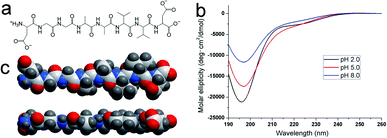 | ||
| Fig. 1 Structural properties of DGAV. (a) Chemical structure. (b) CD spectra at different pH. (c) 3D model from different sides showed a flat-wedge-like geometrical shape of the peptide monomer. | ||
| Dissociable group | pKa | Charge at different pH | ||
|---|---|---|---|---|
| pH = 2.0 | pH = 5.0 | pH = 8.0 | ||
| C-terminal –COOH | 2.09 | Weak (−) | Medium (−) | Strong (−) |
| β-COOH of Asp | 3.86 | Weak (−) | Medium (−) | Strong (−) |
| N-terminal –NH3+ | 9.82 | Strong (+) | Medium (+) | Weak (+) |
| Zeta potential | — | −6.86 | −15.93 | −26.65 |
The far-UV CD spectra of DGAV at pH 2.0, 5.0 and 8.0 are shown in Fig. 1b. All spectra showed a negative band near 195 nm, indicating that the peptide monomers took an irregular secondary structure at all pH values. Based on these results, the 3D molecular model of the peptide monomer could be predicted by using the ICM-Pro software package (MolSoft LLC, San Diego, Calif.). As shown by the model in Fig. 1c, since each amino acid residue alternately appeared at each side of the peptide backbone, the peptide monomer was wedge-shaped on one side due to the increasing size of glycine, alanine and valine, while there's not too much size variation on the other side, making the peptide's geometric shape close to a flat wedge. In our previous study, a similar flat-wedge shape has been proved to facilitate the formation of nanofibers from other peptides,20 so that we supposed that DGAV could also self-assemble into nanofibers in a similar manner.
Formation of nanofibers in solution
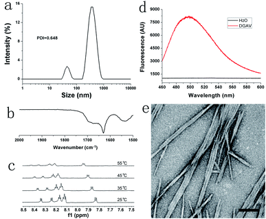
As shown in Fig. 2a, DLS revealed that the size distribution of DGAV in pH 2.0 solution was between 10 and 1000 nm. As a method to measure the hydrodynamic diameter of particle nanostructures, DLS could not accurately measure the size of fibril nanostructures with a high aspect ratio. And the polydispersity index (PDI) value of 0.648 also indicated that the size of nanostructures formed from DGAV varied great. Anyway, this size distribution could confirm the existence of supramolecular nanostructures in the peptide solution. In the FTIR spectrum shown in Fig. 2b, the amide-I band appeared at a lower wavenumber of 1628 cm−1, indicating the formation of strong intermolecular hydrogen bonds.23 On the other hand, the 1H NMR spectrum showed that the amide peaks shifted downfield with the increase of temperature (Fig. 2c). This phenomenon also suggested the formation of intermolecular hydrogen bonds, since higher temperature could weaken hydrogen bonds and protons on the amide groups would shift downfield.24 Both FTIR and NMR results showed that DGAV in solution formed intermolecular hydrogen bonds, which also suggested the peptide's self-assembling behaviour in solution. Furthermore, the ThT-binding test revealed that DGAV binding with ThT in solution showed a fluorescence peak at around 495 nm (Fig. 2d). This fluorescence peak has been well known as a characteristic feature of amyloid-like aggregates,25,26 so that it also suggested the formation of supramolecular nanostructures by the self-assembly of DGAV in solution.As shown in Fig. 2e, the TEM image confirmed that DGAV in solution formed smooth nanofibers with a diameter less than 10 nm, which were morphologically similar to typical amyloid-like fibrils. Noticeably, these nanofibers tended to undergo a parallel alignment instead of crossing over each other, suggesting the existence of interaction among different nanofibers along their axis direction. In conclusion, all these results confirmed that DGAV could self-assemble into nanofibers in aqueous solution. More interestingly, nanofibers formed from DGAV could readily bind with metal ions such as Cu2+ as shown in Fig. S2,† suggesting their potential application as templates for fabricating metallic nanowires.
Formation of nanofiber coils on a mica surface
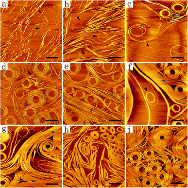
As shown by AFM images in Fig. 3, the nanofibers formed from DGAV exhibited an interesting self-coiling behaviour when incubated on a mica surface. When the peptide solution was added dropwise onto the mica surface and pipetted away immediately without incubation, only very short nanofibers were observed (Fig. 3a). It should be noted that most of the short nanofibers tended to undergo a parallel alignment instead of random and scattered distribution, indicating that some kind of attraction might exist among these nanofibers. On the other hand, as pointed by black arrows in Fig. 3a, a few short nanofibers also showed a tendency of self-bending. After being incubated on the mica surface for 5 min, more clusters of longer nanofibers appeared, and some nanofibers began to undergo obvious self-coiling (Fig. 3b). As pointed by black arrows in Fig. 3b, while most nanofibers tended to be bound together, coils could be formed at the free ends of some nanofibers. This self-coiling behaviour might be induced by the attraction between the free end of a nanofiber and its adjacent section on the same nanofiber, when there's no other nearby nanofibers for it to bind with. After 30 min of incubation, extremely long nanofibers self-coiling into multi-loop coils began to appear (Fig. 3c). As pointed by the black arrow in Fig. 3c, two long nanofibers could bind together and co-coil into a single coil at one of their ends, while the other ends were totally separated and bound with different sets of nanofibers. This result indicated two essential properties of nanofibers formed from DGAV. Firstly, these long nanofibers were highly flexible, which allowed them to be freely bent as intact long nanofibers. Secondly, there's some kind of prevailing attracting force among nanofibers and along their axial direction, which could lead to the binding and self-coiling behaviours. Based on these two properties, it's possible that different sections of the same long nanofiber could independently undergo self-coiling or binding with other nearby nanofibers, forming various patterns on the mica surface.Based on these results, it was expectable that with more long nanofibers deposited on the mica surface by longer-time incubation, their patterning behaviour would get more complicated as induced by their flexibility and prevailing fiber-to-fiber interaction. As shown in Fig. 3d, after 1 h of incubation, both the number of multi-loop coils and the number of loops in each coil increased significantly, forming coil patterns with great diversity. A coil could be generated by simultaneous coiling of several parallel nanofibers (black arrow), or a larger coil could be formed by the coiling of several parallel nanofibers around existing small coils (blue arrow). As shown in Fig. 3e, after 1.5 h of incubation, more densely packed parallel nanofibers began to appear alongside multi-loop coils (blue arrow). As shown in Fig. 3f and g, after 2–6 h of incubation, the mica surface was occupied by multi-loop coils and bundles of parallel nanofibers (blue arrows), and only a few coils formed from single nanofibers could be observed (black arrows). With the incubation time further extended to 12 h, the density of parallel nanofibers and multi-loop coils further increased, and no single nanofibers could be observed (Fig. 3h). After 24 h of incubation, the mica surface was almost completely covered by tightly packed multi-loop coils (Fig. 3i). Some coils had so many loops of nanofibers in them and they even grew into discs with a diameter of more than one micron.
In the past two decades, a lot of SAPNs have been reported, but none of them had such high flexibility to form well-ordered higher-level architectures while maintaining their basic morphology of smooth long nanofibers. For example, with the increase of peptide concentration, a designer amphiphilic peptide exhibited structural transformation from separated short nanofibers into nanowebs as a result of fusion between nanofibers.27 On the other hand, although a peptide reported in our previous study could form similar long nanofibers, these nanofibers exhibited a random stacking behaviour during long-term incubation and formed a three-dimensional scaffold composed of randomly interweaving nanofibers (Fig. S3†). For the first time, the results in our current study showed the formation of flexible long nanofibers, which could form patterns within a two-dimensional space while maintaining their one-dimensional structure. Furthermore, it should be noted that when DGAV nanofibers were combined with Cu2+ ions, they still maintained this self-coiling ability (Fig. S4†), suggesting their potential application as a template for fabricating coiling metal nanowires.
Two mechanisms for nanofiber elongation
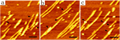
In order to reveal the mechanisms of how DGAV formed such long nanofibers on the mica surface, the AFM image in Fig. 3a was further enlarged and more detailed images are shown in Fig. 4. Black arrows in Fig. 4a indicated that different short nanofibers could be aligned up in an end-to-end manner, generating perfect butt-joints to connect the short nanofibers. On the other hand, as indicated by black arrows in Fig. 4b, different short nanofibers could also be aligned up with their ends overlapping with each other, forming lap-joints to connect the short nanofibers. It should be pointed out that in their initial state lap-joints might be less stable than butt-joints, but the overlapped section of different nanofibers might undergo a fusion process and finally form smooth long nanofibers. As pointed by black arrows in Fig. 4c, fusion nodes on the nanofibers could be identified by their higher brightness in the AMF image, which means that these overlapped sections of two nanofibers could be quickly fused together. Connected by these butt-joints and lap-joints, short nanofibers could further assemble into extremely long nanofibers, which were flexible enough to undergo a complicated coiling process.Self-assembling and patterning model
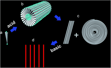
Based on the time-dependent patterning behaviour of DGAV nanofibers shown in Fig. 3, it could be concluded that prevailing attracting force existed among these flexible long nanofibers, while the adhering force of these nanofibers onto the mica surface was very weak. This extremely weak adherence is important to explain why the nanofibers could undergo sliding and coiling on the mica surface. As shown in Fig. 5a and b, a self-assembling model was proposed to demonstrate how hydrophobic interaction among the hydrophobic sections and the special flat-wedge shape of the peptide monomer lead to the formation of flexible long nanofibers. Since one side of the peptide monomer was wedge-shaped, the peptides tended to use this side to form discs with a minimal spatial encumbrance, which became the intersecting faces of the nanofibers. On the other hand, since the other side of the peptide monomer had a constant thickness, these discs were also flat, which further facilitates their axial stacking to form long nanofibers. Considering the special geometrical shape of the peptide monomer, this model provided the most effective architecture of self-assembly. Otherwise, the formation of half-sphere-caps at the end of nanofibers or three-way branches connecting different nanofibers would have to involve extra curvature, so that those structures would be less stable.In this model, all peptide monomers bury their smaller N-terminals inside the cylindrical micelle and expose their bigger C-terminals outside, so that the charge distribution along the outer surface of nanofibers is determined by the charge of the C-terminal groups of the peptide monomer, which bears very weak negative charge at pH 2.0 (Table 1). On the other hand, the C-terminal aspartic acid seems to be too small to cover the relatively bulky hydrophobic valine, so that the outer surface of these nanofibers could also be hydrophobic to some degree. Under these conditions, weak negative charge together with hydrophobicity on the surface of nanofibers would make them poorly attachable to the mica surface, which was negatively charged and hydrophilic. At the same time, since the hydrophobicity on the nanofibers' surface predominated over the weak negative charge, prevailing hydrophobic interaction among nanofibers would predominate over the electrostatic repulsion, leading to the coiling and paralleling behaviour (Fig. 5c). On the other hand, the negative charge on the nanofiber surface also explained why these nanofibers could absorb Cu2+ ions.
Effect of pH on the self-assembling structure
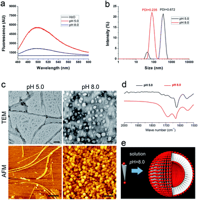
In a previous study, we have proved that solution pH will change the charge distribution of bolaamphiphilic peptides and thus change the surface charge of their self-assembling nanostructure, leading to the alteration of their aggregation behaviour.21 In this study, we wonder whether we can also manipulate the organization of DGAV nanofibers by changing the environmental pH. Our hypothesis was that higher pH would endow the nanofibers' surface with stronger negative charge as shown in Table 1, which might be able to generate strong electrostatic repulsion and separate the nanofibers from each other (Fig. 5d).As shown in Fig. 6a, in peptide solution with a pH value of 5.0 and 8.0, ThT-binding fluorescence suggested that both samples could still form amyloid-like aggregates. However, compared with the fluorescence spectrum of the peptide at pH 2.0 (Fig. 2d), the samples at higher pH showed lower peak values, suggesting the change of self-assembling nanostructures. As shown in Fig. 6b, the peptide at pH 5.0 exhibited two-peak size distribution and polydispersity similar to the peptide at pH 2.0. However, the peptide at pH 8.0 exhibited a totally different single-peak size distribution around 100 nm with a much lower polydispersity, suggesting the formation of a totally different kind of nanostructure.
As shown in Fig. 6c, both TEM and AFM images revealed that at pH 5.0 the peptide also formed nanofibers with an individual morphology similar to those formed at pH 2.0. However, an obvious difference in the patterning behaviour is that the nanofibers didn't show coiling behaviour at all. Although these nanofibers still showed a certain degree of fiber-to-fiber binding, they were not so tightly packed as at pH 2.0. This was understandable since at pH 5.0 when aspartic acid on the surface bears medium negative charge, there's a balance between electrostatic repulsion and hydrophobic interaction, so that attraction among nanofibers was not strong enough to induce the coiling behaviour.
On the other hand, when the solution pH was further increased to 8.0, the peptide underwent an alternative self-assembly process and form homogeneous nanospheres (Fig. 6c), which were totally different from nanofibers observed at lower pH. Furthermore, the peptide at pH 8.0 also exhibited different FTIR spectra compared with the samples at lower pH. As shown in Fig. 6d, except for the amide-I peak at around 1628 cm−1, the peptide at pH 8.0 also exhibited another amide-I peak at a higher wavenumber, suggesting less intensive intermolecular hydrogen bonding in this sample. Based on these results, in Fig. 6e we proposed another model to explain how the peptide formed nanospheres. At pH 8.0, both the N-terminal and C-terminal of DGAV would bear strong negative charge, generating strong electrostatic repulsion between the head groups. As has been suggested by previous studies,21,28 extremely strong electrostatic repulsion between the head groups would greatly increase the curvature of the self-assembly of bolaamphiphilic molecules, leading to the formation of nanovesicles. It should also be pointed out that in both nanofibers and nanovesicles, N-terminal –NH3+ buried inside would bear positive charge, which could generate electrostatic interaction with N-terminal β-COO– and further stabilize the nanostructures from inside. Furthermore, we also tested the self-assembling behaviour of DGAV in extremely acidic or basic solutions. As shown in Fig. S5,† ThT-binding fluorescence and the TEM image indicated that adjusting the pH from 2.0 to 1.0 didn't significantly change the peptide's self-assembling behaviours, while the peptide completely lost its self-assembling ability when the pH was increased to 10.0 and 12.0. These results showed that if we directly increase the pH of peptide solution, it's not possible to manipulate the patterning behaviour of the peptide without changing its basic self-assembling structure of nanofibers.
Straightening of nanofibers
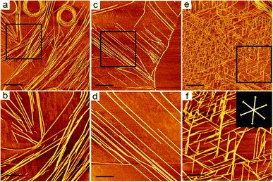
Since the nanofibers formed at pH 2.0 exhibited considerable stability and flexibility, we then proposed an alternative strategy to manipulate their patterning behaviour. If these nanofibers were pre-deposited on a mica surface, basic vapour might be able to change their patterning behaviour without affecting their original morphology. Since in basic vapour DGAV would bear much stronger negative charge at its C-terminal, prevailing strong electrostatic repulsion among negatively charged nanofibers might overwhelm the hydrophobic interaction, which might drive coiled nanofibers to straighten and packed nanofibers to separate from each other.To verify this hypothesis, we incubated the coiled nanofibers in basic ammonia vapour. As expected, AFM images revealed the straightening behaviours of these pre-coiled nanofibers. Firstly we deposited the peptide sample on a mica surface by 30 min of regular incubation, and then subjected it to incubation in ammonia vapour. As shown in Fig. 7a and b, after 8 h of incubation in ammonia vapour, the tightly packed nanofiber coils began to straighten and separate from each other. Nanofiber coils, bundles of parallel nanofibers and separated nanofibers co-existed in Fig. 7a, indicating that the transformation from coils into separated nanofibers was also a gradual process. As shown in Fig. 7b, some broken short nanofibers co-existed with longer nanofibers. It's likely that prevailing electrostatic repulsion among the nanofiber coils could drive the straightening of different sections of different nanofibers simultaneously, and in this process some nanofibers were blocked by other nanofibers so that they were broken by the repulsion. Fig. 7c and d show that further incubating the deposited nanofibers in ammonia vapour for 12 h lead to the formation of totally separated parallel nanofibers. As shown in Fig. 7d, these nanofibers could become perfectly straight and parallel. Although it seemed to be inevitable that some nanofibers would be broken in the process of straightening, it's still possible to get straight nanofibers with a length of several microns.
We have also investigated the ammonia-induced self-straightening behaviour of nanofiber coils deposited on a mica surface by 1 h of regular incubation. Since in this situation more nanofibers were pre-deposited and more tightly packed coils were pre-formed, the prevailing repulsion might lead to more complicated straightening behaviour. As shown in Fig. 7e, a network of short nanofibers was formed. It was possible that with more nanofiber coils deposited on the mica surface, they were more likely blocked by other nearby nanofibers, so that most nanofibers were broken into short ones by the repulsion and formed a network. As shown in Fig. 7f, these short nanofibers seemed to be aligned hexagonally on the mica surface. Such special patterning behaviours of nanofibers or nanotapes were also reported by other researchers and were supposed to be caused by the hexagonally symmetrical alignment of atoms on the mica surface.29–31
Transformation of single isolated nanofibers
Except for those complex patterns described above, it would also be interesting to get a single-nanofiber coil that could be transformed into a single straight long nanofiber. However, it seemed to be a paradox to get a long nanofiber attached on the mica surface without depositing too many nanofibers nearby. In order to resolve this problem, we diluted DGAV solution to 0.5 mM and subjected it to the deposition process. As expected, by incubating the diluted peptide solution on a mica surface for 1 h, we were able to obtain nanofiber coils mostly formed by isolated nanofibers with a length of more than ten microns (Fig. S6†). As shown in Fig. 8a, by incubating the diluted peptide solution on a mica surface for 30 min, an isolated double-loop coil formed by a single nanofiber could be obtained (black arrow). Consequently, further incubating the sample in ammonia vapour for another 10 h generated very long isolated straight nanofibers (Fig. 8b and c). These results suggested that by simply diluting the peptide sample to reduce the number of nanofibers in the solution and adjusting the depositing time, we were able to get isolated nanofibers and control their conformational transformation from coils into straight nanofibers. | ||
| Fig. 8 AFM images of a single-nanofiber coil (a) and isolated straight nanofibers (b and c). Scale bars = 1 μm. | ||
Conclusions
In this study we have presented the self-assembling and self-patterning behaviour of a designer peptide with the shape of a flat wedge. By incubation on a mica surface, the peptide could form micro-coils composed of ultra-flexible long nanofibers. Considering their high aspect ratio, high flexibility and ability to absorb metal ions, these nanofibers might be useful in the field of nanofabrication. Furthermore, by adjusting peptide concentration, incubation time and environmental pH, the nanofiber coils could undergo re-organization and form different patterns composed of straightened nanofibers. Although pH-responsiveness has been reported as a conventional strategy to control the self-assembling behaviours of designer molecules, it usually leads to the morphological change of the nanostructures instead of changing their patterning behaviours,32–36 while in our study, we showed the possibility to control the patterning behaviours of pre-formed nanostructures in a pH-responsive manner without changing their original morphology. On the other hand, generally a pH-responsive strategy is used in solution to control the self-assembling behaviour of designer molecules, while our study indicated that adjusting the vapour pH might be a useful strategy to control the self-patterning behaviour of pH-responsive nanostructures. Although this strategy for fabricating nanopatterns still lacks sufficient accuracy in its current stage, it implicated the possibility of intentionally inducing the self-assembling and self-patterning behaviours of nanostructures, providing a promising way to get highly ordered architectures for developing nanotechnology.Author contributions
Yongzhu Chen: investigation, data curation and writing – original draft; Feng Qiu: conceptualization, supervision, investigation, funding acquisition and writing – review & editing; Chengkang Tang: investigation; Zhihua Xing: methodology; Xiaojun Zhao: conceptualization, supervision, funding acquisition and writing – review & editing.Conflicts of interest
There are no conflicts to declare.Acknowledgements
This work was supported by the National Clinical Research Center for Geriatrics, West China Hospital, Sichuan University (Z2018B21), the National Natural Science Foundation of China (No. 81973274, No. 81000658 and No. 31100565) and the National 985 Key Project of Sichuan University of the Education Ministry of China.References
- Y. Yao, L. Zhang, E. Orgiu and P. Samorì, Unconventional nanofabrication for supramolecular electronics, Adv. Mater., 2019, 31, e1900599 CrossRef.
- F. Galeotti, M. Pisco and A. Cusano, Self-assembly on optical fibers: a powerful nanofabrication tool for next generation “lab-on-fiber” optrodes, Nanoscale, 2018, 10, 22673–22700 RSC.
- X. Wang, F. Sun, G. Yin, Y. Wang, B. Liu and M. Dong, Tactile-sensing based on flexible PVDF nanofibers via electrospinning: a review, Sensors, 2018, 18, E330 CrossRef.
- W. Zhong, C. Liu, Q. Liu, L. Piao, H. Jiang, W. Wang, K. Liu, M. Li, G. Sun and D. Wang, Ultrasensitive wearable pressure sensors assembled by surface-patterned polyolefin elastomer nanofiber membrane interpenetrated with silver nanowires, ACS Appl. Mater. Interfaces, 2018, 10, 42706–42714 CrossRef CAS.
- S. H. Ji and J. S. Yun, Fabrication and characterization of aligned flexible lead-free piezoelectric nanofibers for wearable device applications, Nanomaterials, 2018, 8, E206 CrossRef.
- Z. Wang, S. Zhao, A. Huang, S. Zhang and J. Li, Mussel-inspired codepositing interconnected polypyrrole nanohybrids onto cellulose nanofiber networks for fabricating flexible conductive biobased composites, Carbohydr. Polym., 2019, 205, 72–82 CrossRef CAS.
- L. Zeng, Y. Jiang, J. Xu, M. Wang, W. Li and Y. Yu, Flexible copper-stabilized sulfur-carbon nanofibers with excellent electrochemical performance for Li-S batteries, Nanoscale, 2015, 7, 10940–10949 RSC.
- K. Tao, P. Makam, R. Aizen and E. Gazit, Self-assembling peptide semiconductors, Science, 2017, 358, eaam9756 CrossRef.
- X. Hu, M. Liao, H. Gong, L. Zhang, H. Cox, T. A. Waigh and J. R. Lu, Recent advances in short peptide self-assembly: from rational design to novel applications, Curr. Opin. Colloid Interface Sci., 2020, 45, 1–13 CrossRef CAS.
- S. Li, R. Xing, R. Chang, Q. Zou and X. Yan, Nanodrugs based on peptide-modulated self-assembly: design, delivery and tumor therapy, Curr. Opin. Colloid Interface Sci., 2018, 35, 17–25 CrossRef CAS.
- I. A. Banerjee, L. Yu and H. Matsui, Cu nanocrystal growth on peptide nanotubes by biomineralization: size control of Cu nanocrystals by tuning peptide conformation, Proc. Natl. Acad. Sci. U. S. A., 2003, 100, 14678–14682 CrossRef CAS.
- M. Reches and E. Gazit, Casting metal nanowires within discrete self-assembled peptide nanotubes, Science, 2003, 300, 625–627 CrossRef CAS.
- L. Li and S. I. Stupp, One-dimensional assembly of lipophilic inorganic nanoparticles templated by peptide-based nanofibers with binding functionalities, Angew. Chem., Int. Ed., 2005, 44, 1833–1836 CrossRef CAS.
- O. Carny, D. E. Shalev and E. Gazit, Fabrication of coaxial metal nanocables using a self-assembled peptide nanotube scaffold, Nano Lett., 2006, 6, 1594–1597 CrossRef CAS.
- H. Jiang and S. I. Stupp, Dip-pen patterning and surface assembly of peptide amphiphiles, Langmuir, 2005, 21, 5242–5246 CrossRef CAS.
- M. Reches and E. Gazit, Controlled patterning of aligned self-assembled peptide nanotubes, Nat. Nanotechnol., 2006, 1, 195–200 CrossRef CAS.
- V. Dinca, E. Kasotakis, J. Catherine, A. Mourka, A. Ranella, A. Ovsianikov, B. N. Chichkov, M. Farsari, A. Mitraki and C. Fotakis, Directed three-dimensional patterning of self-assembled peptide fibrils, Nano Lett., 2008, 8, 538–543 CrossRef CAS.
- V. Dinca, E. Kasotakis, J. Catherine, A. Mourka, A. Mitraki, A. Popescu, M. Dinescu, M. Farsari and C. Fotakis, Development of peptide-based patterns by laser transfer, Appl. Surf. Sci., 2007, 254, 1160–1163 CrossRef CAS.
- F. Qiu, Y. Chen and X. Zhao, Comparative studies on the self-assembling behaviors of cationic and catanionic surfactant-like peptides, J. Colloid Interface Sci., 2009, 336, 477–484 CrossRef CAS.
- Y. Chen, F. Qiu, Y. Lu, Y. Shi and X. Zhao, Geometrical shape of hydrophobic section determines the self-assembling structures of peptide detergents and bolaamphiphilic peptides, Curr. Nanosci., 2009, 5, 69–74 CrossRef CAS.
- F. Qiu, C. Tang and Y. Chen, Amyloid-like aggregation of designer bolaamphiphilic peptides: effect of hydrophobic section and hydrophilic heads, J. Pept. Sci., 2018, 24, e3062 CrossRef.
- Y. Chen, C. Tang, Z. Xing, J. Zhang and F. Qiu, Ethanol induced the formation of β-sheet and amyloid-like fibrils by surfactant-like peptide A6K, J. Pept. Sci., 2013, 19, 708–716 CrossRef CAS.
- W. K. Surewicz, H. H. Mantsch and D. Chapman, Determination of protein secondary structure by Fourier transform infrared spectroscopy: a critical assessment, Biochemistry, 1993, 32, 389–394 CrossRef CAS.
- S. Ahmed, J. H. Mondal, N. Behera and D. Das, Self-assembly of peptide-amphiphile forming helical nanofibers and in situ template synthesis of uniform mesoporous single wall silica nanotubes, Langmuir, 2013, 29, 14274–14283 CrossRef CAS.
- H. Naiki and K. Nakakuki, First-order kinetic model of Alzheimer's beta-amyloid fibril extension in vitro, Lab. Invest., 1996, 74, 374–383 CAS.
- P. Friedhoff, A. Schneider, E. M. Mandelkow and E. Mandelkow, Rapid assembly of Alzheimer-like paired helical filaments from microtubule-associated protein tau monitored by fluorescence in solution, Biochemistry, 1998, 37, 10223–10230 CrossRef CAS.
- L. Ruan, H. Zhang, H. Luo, J. Liu, F. Tang, Y. Shi and X. Zhao, Designed amphiphilic peptide forms stable nanoweb, slowly releases encapsulated hydrophobic drug, and accelerates animal hemostasis, Proc. Natl. Acad. Sci. U. S. A., 2009, 106, 5105–5110 CrossRef CAS.
- Y. Yan, W. Xiong, X. Li, T. Lu, J. Huang, Z. Li and H. Fu, Molecular packing parameter in bolaamphiphile solutions: adjustment of aggregate morphology by modifying the solution conditions, J. Phys. Chem. B, 2007, 111, 2225–2230 CrossRef CAS.
- T. Akutagawa, T. Ohta, T. Hasegawa, T. Nakamura, C. A. Christensen and J. Becher, Formation of oriented molecular nanowires on mica surface, Proc. Natl. Acad. Sci. U. S. A., 2002, 99, 5028–5033 CrossRef CAS.
- C. Whitehouse, J. Fang, A. Aggeli, M. Bell, R. Brydson, C. W. G. Fishwick, J. R. Henderson, C. M. Knobler, R. W. Owens, N. H. Thomson, D. A. Smith and N. Boden, Adsorption and self-assembly of peptides on mica substrates, Angew. Chem., Int. Ed., 2005, 117, 2001–2004 CrossRef.
- F. Zhang, H. Du, Z. Zhang, L. Ji, H. Li, L. Tang, H. Wang, C. Fan, H. Xu, Y. Zhang, J. Hu, H. Hu and J. He, Epitaxial growth of peptide nanofilaments on inorganic surfaces: effects of interfacial hydrophobicity/hydrophilicity, Angew. Chem., Int. Ed., 2006, 45, 3611–3613 CrossRef CAS.
- J. S. Capes, P. J. Kiley and A. H. Windle, Investigating the effect of pH on the aggregation of two surfactant-like octapeptides, Langmuir, 2010, 26, 5637–5644 CrossRef CAS.
- S. Li, A. Hao, J. Shen, N. Shang and C. Wang, UV and pH-responsive supra-amphiphiles driven by combined interactions for controlled self-assembly behaviors, Soft Matter, 2018, 14, 2112–2117 RSC.
- J. Sun, W. Wei, D. Zhao, Q. Hu and X. Liu, Liquid marbles prepared from pH-responsive self-assembled micelles, Soft Matter, 2015, 11, 1954–1961 RSC.
- N. Feng, G. Han, J. Dong, H. Wu, Y. Zheng and G. Wang, Nanoparticle assembly of a photo- and pH-responsive random azobenzene copolymer, J. Colloid Interface Sci., 2014, 421, 15–21 CrossRef CAS.
- J. Zhang, B. Farias-Mancilla, I. Kulai, S. Hoeppener, B. Lonetti, S. Prévost, J. Ulbrich, M. Destarac, O. Colombani, U. S. Schubert, C. Guerrero-Sanchez and S. Harrisson, Effect of hydrophilic monomer distribution on self-assembly of a pH-responsive copolymer: spheres, worms and vesicles from a single copolymer composition, Angew. Chem., Int. Ed., 2020 DOI:10.1002/anie.202010501.
Footnote |
| † Electronic supplementary information (ESI) available: Supplementary illustration of the incubation method, supporting TEM and AFM images, and ThT-binding fluorescence spectra. See DOI: 10.1039/d0na00892c |
| This journal is © The Royal Society of Chemistry 2021 |

