 Open Access Article
Creative Commons Attribution 3.0 Unported Licence
Magnetic gas sensing: working principles and recent developments
Pratik V.
Shinde
 and
Chandra Sekhar
Rout
 *
*
Centre for Nano and Material Sciences, Jain University, Jain Global Campus, Jakkasandra, Ramanagaram, Bangalore, 562112, India. E-mail: r.chandrasekhar@jainuniversity.ac.in; csrout@gmail.com
First published on 23rd January 2021
Abstract
Gas sensors work on the principle of transforming the gas adsorption effects on the surface of the active material into a detectable signal in terms of its changed electrical, optical, thermal, mechanical, magnetic (magnetization and spin), and piezoelectric properties. In magnetic gas sensors, the change in the magnetic properties of the active materials is measured by one of the approaches such as Hall effect, magnetization, spin orientation, ferromagnetic resonance, magneto-optical Kerr effect, and magneto-static wave oscillation effect. The disadvantages of different types of gas sensors include their chemical selectivity and sensitivity to humidity and high-temperature operation. For example, in the case of chemiresistive-type gas sensors, the change in the sensor resistance can drastically vary in the real environment due to the presence of other gas species and the overall electrical effect is quite complex due to simultaneous surface reactions. Further, it is not easy to make stable contacts for powdered samples for the conventional electrical property-based gas sensors. Fire hazard is another issue for the electrical property-based hydrogen gas sensors due to their flammable nature at higher operating temperature. In this regard, to solve these issues, magnetic gas sensor concepts have emerged, in which the magnetic properties of the materials get modified when exposed to gas molecules. In this review article, the working principles, fundamentals, recent developments, and future perspectives in magnetic gas sensors are reviewed. Finally, the prospects and opportunities in these exciting fields are also commented upon based on their current progress.
1 Introduction
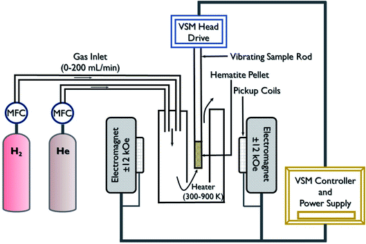
A gas-sensing system or electronic nose can qualitatively or quantificationally detect specific gases, which is important in various applications such as industrial pollutant gas leakage detection (e.g., H2, NO2, NH3, H2S, CO, and SO2), environmental monitoring, medical care, food industry, and homeland security.1–7 The performance of an ideal gas sensor is evaluated by its high responsivity, fast response/recovery times, great stability/repeatability, good selectivity, room-working temperature, low cost, and easy fabrication for practical applications.1–7 Gas sensors work on the principle of transforming gas adsorption on the surface of the active material into a detectable signal in terms of its changed electrical, optical thermal, mechanical, magnetic (magnetization and spin), and piezoelectric properties. Depending on these principles, many types of gas sensors with different transductions forms are developed, which include chemiresistors, field-effect transistors (FETs), Schottky and junction diode sensors, solid-state electrochemical sensors (SSES), quartz crystal microbalance (QCM), gas capacitors, surface acoustic wave (SAW), and plasmonic and surface-enhanced Raman spectroscopy (SERS) sensors. In chemiresistive-type gas sensor devices, the change in the system resistance or conductance due to gas adsorption is measured.1–7 In magnetic gas sensors, the change in the magnetic properties of the active materials is measured by one of the approaches such as Hall effect, magnetization, spin orientation, ferromagnetic resonance, magneto-optical Kerr effect, and magneto-static wave oscillation effect.8,9 Surface acoustic wave gas sensing utilizes the advantage of the piezoelectric effect of the sensor material, whose frequency gets shifted by the adsorption of analyte gas molecules.10–13 Optical gas sensors detect the gas species by monitoring their optical properties such as optical absorption, transmission, refractive index, and surface plasmon effects due to the interaction of the gas molecules with the active materials.11–13 New opportunities for sensing devices involve hot topics such as the internet of things (IoT) devices, wearable, flexible, and self-powered devices. Hence, research activities in these areas will lead to the fabrication of low cost, low power, small size, long term stability, and selective gas sensors for the detection of dangerous gas species.11–14The disadvantages of different types of gas sensors include their chemical selectivity and sensitivity to humidity and high-temperature operation. For example, in the case of chemiresistive-type gas sensors, the change in the sensor resistance can drastically vary in the real environment due to the presence of other gas species and the overall electrical effect is quite complex due to simultaneous surface reactions.11–14 Further, it is not easy to make stable contacts for powdered samples for the conventional electrical property-based gas sensors. Fire hazard is another issue for the electrical property-based hydrogen gas sensors due to their flammability at higher operating temperature. In this regard, to solve these issues, magnetic gas sensor concepts have emerged, in which the magnetic properties of the materials get modified when exposed to gas molecules. These magnetic gas sensors are compatible with the processes involved in the fabrication of silicon devices and hence allows the integration of the sensors with on-chip devices.15–17 Systematic changes in the magnetic properties and exchange coupling, when exposed to gases, are monitored by different laboratory magnetometric techniques and equipment such as superconducting quantum interference devices (SQUID), vibrating sample magnetometers (VSM), polarized neutron reflectivity, X-ray resonant magnetic scattering (XRMS), Hall effect, optical Kerr effect, and ferromagnetic resonance setups.15–17 Moreover, nanomaterials also play a significant role in the further improvement of the gas sensor's performance. The nanomaterials show exceptional physical, chemical, as well as optoelectronic properties compared to their bulk counterparts.18–22 The high sensing performance comes from their high surface area and controlled grain size. Both these parameters expose more surface volume ratio for the gas sensing process. Their high surface area and controlled grain size play a significant role in achieving high sensing performance. In this review article, the working principles, fundamentals, and recent developments in magnetic gas sensors-based on different materials are reviewed. Furthermore, the future perspectives of magnetic gas sensors are discussed in the conclusion section.
2 Overview, theories, working principles, and recent developments of magnetic gas sensing
Several effects of magnetism such as the Hall effect, Kerr effect, magnetization, spin change effects, the ferromagnetic resonance (FMR) effect, magneto-plasmonic effect, and magneto-static spin-wave (MSW) effect are employed for magnetic gas sensing applications (Fig. 1).22–26 Powder, thin films, and nanomaterials with magnetic (ferro- and antiferromagnets), diluted magnetic semiconducting (DMS) properties, and Pd alloys with transition metals (Co, Ni, Fe, Mn, and Cu) have been employed for magnetic gas sensing applications using different magnetic effects. Compared to their electrical property-based gas sensor counterparts, magnetic gas sensors have emerged as the more attractive candidate due to the following reasons: (i) no electrical contacts are needed to detect the gas, which lowers the risk of explosion due to fire when used in hydrogen-powered vehicles or in the presence of reactive chemicals or pollutants, (ii) magnetic response is much faster compared to chemiresistive sensors, (iii) the working temperature of the sensors can be room-temperature and can be tuned to a very low or very high temperature by choosing magnetic materials with different Curie temperatures (Tc).27–30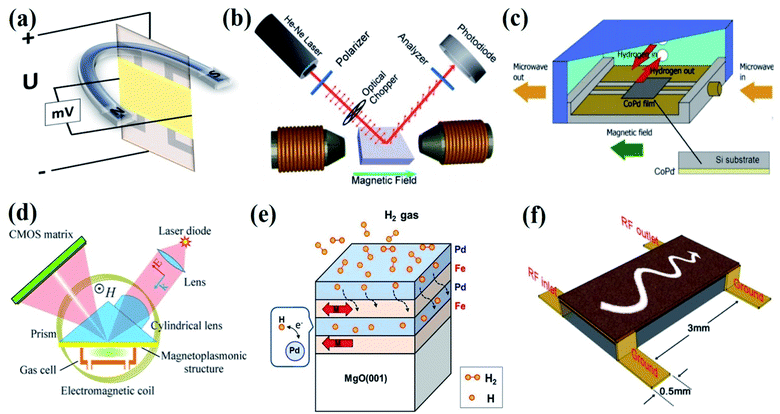 | ||
| Fig. 1 Magnetic effects used for the gas sensing device fabrication. (a) Hall effect, (b) Kerr effect. Reprinted with permission from ref. 22. Copyright (2016) Royal Society of Chemistry. (c) Ferromagnetic resonance (FMR) effect. Reprinted with permission from ref. 23. Copyright (2019) Elsevier. (d) Magneto-plasmonic effect. Reprinted with permission from ref. 24. Copyright (2016) Springer Nature. (e) Magnetic moment or spin effect. Reprinted with permission from ref. 25. Copyright (2018) Springer Nature. (f) Magnetostatic spin-wave (MSW) effect. Reprinted with permission from ref. 26. Copyright (2015) Royal Society of Chemistry. | ||
2.1 Magnetization change-based magnetic gas sensors
Glover et al.33 showed the adsorption of sulfur dioxide by CoFe2O4 nanoparticles and the corresponding changes in magnetism. Sulfur dioxide forms a sulfate upon adsorption on the particle surface by the chemisorption mechanism. Fig. 3a shows (transmission electron microscopy) the TEM images of CoFe2O4 magnetic nanoparticles (MNPs). Fig. 3b showing the Fourier transform infrared (FTIR) spectra of the native MNPs before exposure to sulfur dioxide as well as MNPs after exposure (test 1) and MNPs after exposure but without desorption (tests 2 and 3). The spectra of all the three tests are nearly identical, signifying that sulfur dioxide is retained on the surface of the MNPs. The magnetic susceptibility curves for MNPs samples before and after sulfur dioxide adsorption experiments are shown in Fig. 3c. As compared to the unexposed MNPs, the saturation magnetization decreases by 20%, the remnant magnetization decreases by 23%, and the coercivity decreases by 9% for CoFe2O4 MNPs after sulfur dioxide adsorption. The changes induced by gas adsorption are attributed to the magnetic metal cations at the surface layer of the nanoparticles that are coordinated with sulfur dioxide, which reduces the spin-orbital coupling and surface anisotropy.
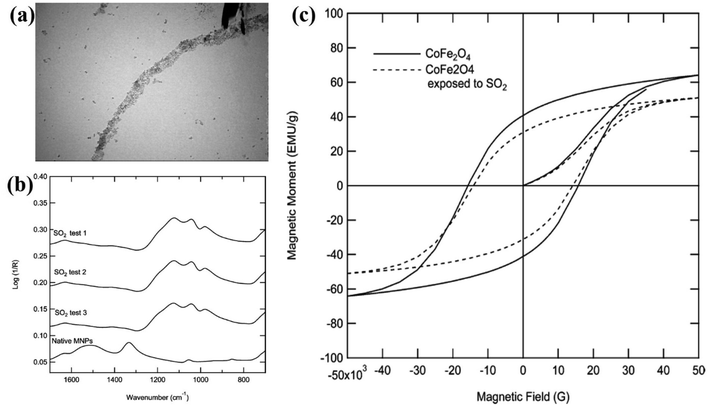 | ||
| Fig. 3 (a) TEM images of CoFe2O4 MNPs. (b) FTIR spectra of the native MNPs before exposure to sulfur dioxide as well as MNPs after exposure (test 1) and MNPs after exposure but without desorption (tests 2 and 3). (c) Magnetic susceptibility curves for MNPs both before and after sulfur dioxide breakthrough experiments. Reprinted with permission from ref. 33. Copyright (2012) American Chemical Society. | ||
The saturation magnetization and perpendicular anisotropy energy (Kp) of Co/Pd multi-layered films are reported to change the reversibility with H2 gas adsorption and desorption.34–38 The change in Ms and magnetic anisotropy are attributed to electronic transfer to the Pd band near the Co/Pd interfaces when H2 is adsorbed. Electron transfer from Pd to the transition metal lowered the difference between the density of states of the spin-up and spin-down electrons at the Fermi level, leading to a net change in its magnetic properties.36–38 Similarly, magnetic coupling in Fe/Nb and Fe/V multi-layered films can be changed by hydrogen absorption, which was confirmed by SQUID magnetization measurements.39–41 Though the method is effective, the high cost and tricky optimization of several setup parameters limit its application.
2.2 Hall effect-based magnetic gas sensors
For oxidizing gas,
| S0 = (Vg − Va)/Va | (1) |
For reducing gas,
| S0 = (Va − Vg)/Vg | (2) |
| VH = RH × (Ix × Bz)/dy | (3) |
Since for the semiconductor, the Hall resistance,
| RH = 1/e × [(p − nb2)/(p + nb)2] | (4) |
From the law of mass action, p = ni2/n, where ni is the electron and hole concentration in an undoped semiconductor material. Using a normalized electron concentration, x = n/ni
 | (5) |
By using these relations, the Hall co-efficient for the active sensor materials in the presence and absence of the gases can be evaluated.
Gerber et al.15 employed the EHE effect for magnetic H2 gas sensing applications of the Pd/Co film as the sensor material. By following their approach, the electric current flowing along the magnetic film generates a voltage in the direction perpendicular to the current direction.
| VH = RHI = I/t(ROHEB + REHEμ0M) | (6) |
R OHE is the ordinary Hall effect coefficient related to the Lorentz force acting on moving charge carriers and REHE is the extraordinary Hall effect coefficient associated with a break in the right-left symmetry at spin–orbit scattering in magnetic materials. Since the EHE term is significantly high, i.e., REHE ≫ ROHE,
| RH = VH/I = μ0REHEM/t | (7) |
 indicate the dominance of the right hand over the left-hand spin-orbital scattering.
The Co/Pd films rich in Co exhibited +ve polarity, whereas the Pd-rich sample exhibited −ve polarity. The sensitivity of the magnetic gas sensors based on the EHE contribution can be calculated by the formula
 | (8) |
| ΔRH, norm(y) = ΔRH(y)/RH(0) = [RH(y) − RH(0)]/RH(0) | (9) |
Hammond et al.44 designed a tin-oxide-based sensor, viz., the Hall effect sensor as shown in Fig. 4a and its cross-sectional view is presented in Fig. 4b. The sensor is made up of four layers, wherein the bottom silicon layer (0.3 mm thick) served as a support for the remaining layers. The insulator layer of silicon dioxide between the silicon substrate and the remaining sensor component is nearly 1 μm thick. The third rectangular layer of tin oxide (0.5 mm × 2.0 mm × 1100 Å) shows good adhesion to the SiO2 surface during deposition and operation. The fourth layer was made up of 3000 Å-thick platinum, consisting of electrodes, in order to measure the conductivity, temperature, and hall voltage. The Hall effect is the induction of transverse voltage in a current-carrying conductor when the conductor is exposed to the magnetic field. Here, the magnetic field is applied perpendicular to the tin oxide surface using a 5403 electromagnet system. The Hall voltage (VH) was measured before exposure to H2 in air and after the sensor reached the maximum conductivity level when exposed to H2 in air. The values for conductivity (σ), electron density (η), and Hall mobility (μH) in air as a function of the operating temperature are shown in Fig. 4c. The Hall mobility remains stable compared to the variation in the conductivity and electron density. All the films have Hall mobility value in the range of 0.9 cm2 V−1 s−1 to 1.83 cm2 V−1 s−1. The experimental results indicated that the Hall mobility sensitivity slightly increased with the operating temperature and weakly depends on the H2 concentration in air.
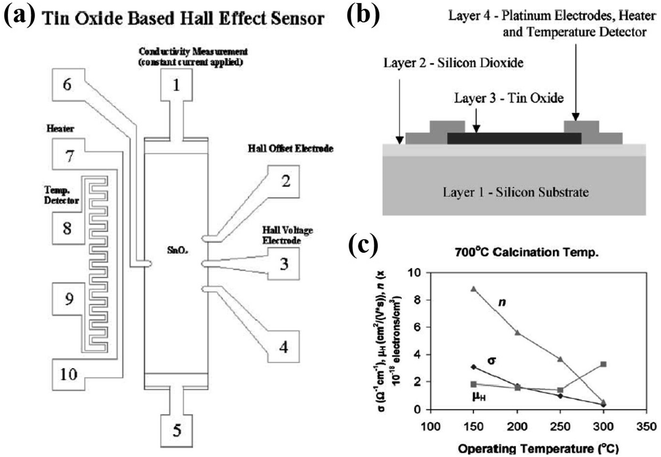 | ||
| Fig. 4 (a) Tin-oxide based Hall effect sensor. (b) Cross-sectional view of the tin-oxide based Hall effect sensor. (c) Tin oxide thin film conductivity (σ), electron density (η), and Hall mobility (μH) in air vs. operating temperature for sensor calcined at 700 °C. Reprinted with permission from ref. 44. Copyright (2001) Elsevier. | ||
| NO2(gas) + e− → NO2(ads)− | (10) |
| NO2(gas) + O2(ads)− + 2e− → NO2(ads)− + 2O(ads)− | (11) |
Due to these surface reactions, the electron concentration on the surface of WO3 decreases when the electron concentration is greater than 1.14ni. This process helped to increase the Hall coefficient, correspondingly increasing the Hall voltage in the presence of NO2 gas.43 Based on similar working principles, the SnO2 nanowires-based Hall sensor showed good H2 sensing properties with a response of 7.81 towards 1000 ppm H2 at 125 °C.21 From the experimental observations, it has been demonstrated that the Hall coefficient of the gas sensor devices was dependent on the gas concentration and the high surface area of the nanostructures helped to achieve enhanced gas-sensing performance.
Lin et al.47 reported the detection of H2S at room temperature using ZnO sensors based on the Hall effect. The electrical and sensing characteristics of the sensors (Fig. 5a) were detected through the bench system under ambient temperature, as shown in Fig. 5b. The sensor was placed in a magnetic field perpendicular to the current, which is moving through the sensor. A constant voltage of 5 V was continuously supplied to the sensor circuit from a power supply and the Hall voltage of the sensor was measured using different concentrations of the gas. At room temperature, the response of the sensor increases exponentially along with increasing gas concentration (Fig. 5c). For 100 ppm H2S, the recovery and response time was 82 s and 35 s, respectively. As the concentration increased, the response time becomes shorter and the recovery time becomes longer (Fig. 5d). From Fig. 5e, it was observed that the Hall effect sensor displayed a negligible response to acetone and ethanol. Also, the sensor showed a higher response to 60 ppm H2S than that at 200 ppm NH3 and 60 ppm NO2. The behavior of the sensor based on the Hall effect to H2S is associated with a change in the electron concentration and has potential applications in actively detecting toxic gas without using any electrical power.
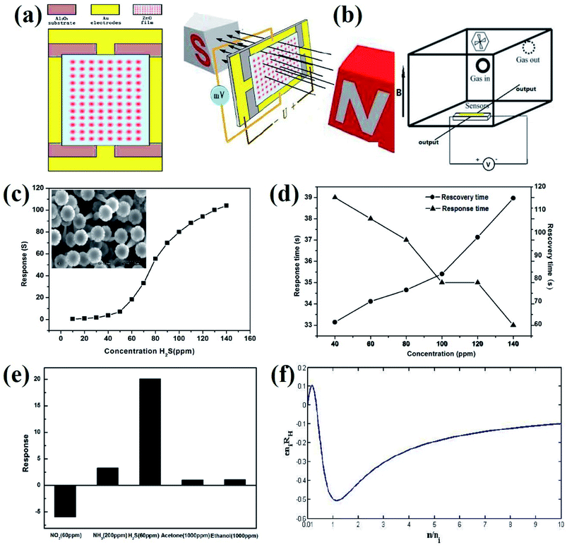 | ||
| Fig. 5 (a) Schematic of the sensor. (b) Measurement system for testing gas sensors. (c) Response of the Hall effect sensor to H2S with varied concentration of 10–140 ppm. Inset: Scanning electron microscopic image of the ZnO sample. (d) The response and recovery time of the Hall effect sensor to various concentrations of H2S. (e) The response of the Hall effect sensor to various gases. (f) Normalized Hall coefficient vs. normalized electron concentration. Reprinted with permission from ref. 47. Copyright (2017) ESG. | ||
Shafiei and his group fabricated conductometric sensors based on an oxidized liquid metal galinstan layer and investigated their sensitivity towards NO2, NH3, and CH4 gases.48Fig. 6a and b indicates the negative Hall coefficients as a function of the magnetic field for Sensor 2. Also, a linear relationship between the sheet carrier density, ns, and magnetic field is given. Fig. 6c indicates the higher response of Sensor 2 than Sensor 1, which is attributed to better film coverage (as confirmed by scanning electron microscopy (SEM)) and a larger active surface area for gas interaction. A response of 7.7% and 5.4% was recorded for 12 ppm NO2 using Sensor 2 and Sensor 1, respectively (Fig. 6d). The Hall effect measurements revealed that the p-type oxide film influenced the sensing response towards different gases.
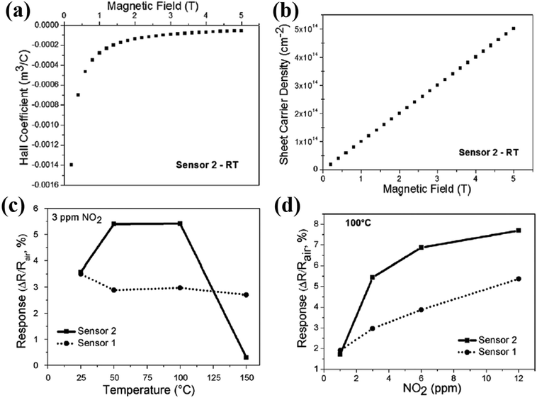 | ||
| Fig. 6 (a) Hall coefficient. (b) Sheet carrier density of the as-deposited galinstan film (Sensor 2, 10 μm thickness). (c) Response of the as-deposited sensors towards 3 ppm NO2 as the function of the operating temperature. (d) Response amplitude of the as-deposited sensors as a function of NO2 concentration. Reprinted with permission from ref. 48. Copyright (2017) Elsevier. | ||
Extra-ordinary Hall phenomena (EHE, eqn (6)–(9)) are employed in ferromagnetic Co/Pd films for hydrogen gas sensing applications.15,49 Due to the high solubility of hydrogen in Pd, it is usually chosen to make stacked layers of Pd with the transition metal for H2 sensing. The palladium lattice expands significantly with the absorption of H2 (0.15% for α-phase and 3.4% for β-phase), which leads to the formation of palladium hydride; this phenomenon is usually employed for the fabrication of H2 sensors based on Co–Pd alloys and multi-layered films.15,50–52 Field dependence of the Hall resistivity of the CoxPd1−x film (0 ≤ x ≤ 0.4) displayed that the polarity reverses between x = 0.15 and x = 0.2. Samples with richer Co content were found to exhibit positive polarity while samples with richer Pd content showed negative polarity. Hall effect resistance as a function of the magnetic field for the CoxPd1−x films in H2 (4%) showed changes in the hysteresis loop area. The Hall effect (EHE) in the optimized sample (Co0.17Pd0.83) showed a sensitivity > 240% per 104 ppm at H2 concentration below 0.5% in the hydrogen/nitrogen atmosphere, which was 2 orders of magnitude higher than that of the conductance-based sensor. From the detailed H2 sensing studies, it was demonstrated that depending on the film composition, thickness, and field of operation, enhanced EHE response of the Co/Pd films could be achieved and these types of materials emerge as an attractive candidate for magnetic gas sensing.15,49 Hall effect-based sensors depend on the operating temperature, p- or n-type conductivity of the material, as well as on the film composition, thickness, and field of operation.
2.3 Kerr effect-based magnetic gas sensors
| S = (Bair − Bgas)/Bgas | (12) |
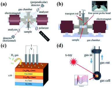 | ||
| Fig. 7 MOKE experimental set up used for magnetic gas sensing: (a) Top and (b) side views along with the four-probe electrical measurement set up. (c) Schematic illustration of the multi-layered films with respect to the four-probe measurements under H2 atmosphere. (d) Gas cell integrated with the in situ X-ray characterization. Reprinted with permission from ref. 16. Copyright (2017) American Institute of Physics. | ||
The change in the Kerr intensity of the reflected light in positive and negative directions (+m and −m) as a parabolic function of the analyzer angle (φ) is represented by
 | (13) |
Also, the relative change in the Kerr rotation angle is defined by
 | (14) |
 | (15) |
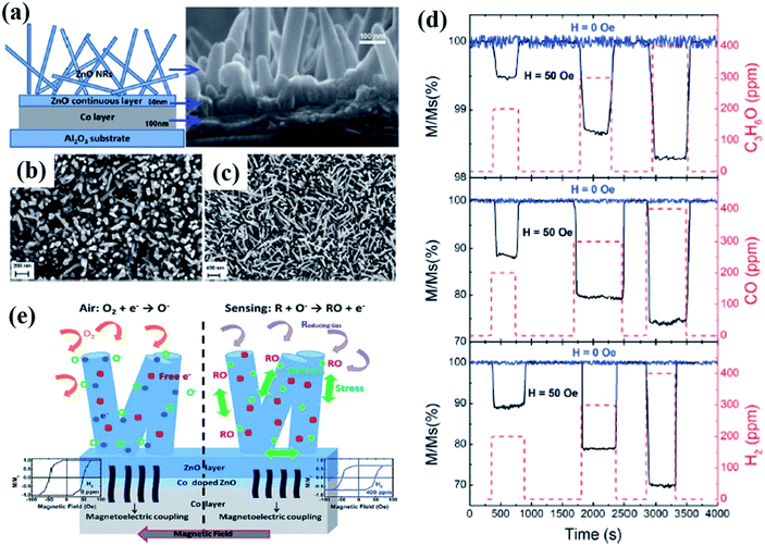 | ||
| Fig. 8 Magnetic gas sensing of the ZnO/Co nanorods by the MOKE magnetometer. (a) Schematic illustration and SEM images of the ZnO nanorods grown on Co-layer, SEM images of (b) MGS1 and (c) MGS2 ZnO nanorods. (d) Magnetization induced gas sensing performance of the MGS2 sample with different concentrations of C3H5O, CO, and H2 with (50 Oe: black) and without (blue lone) an applied magnetic field. (e) Schematic representation of the magnetic gas sensing process and an example of the hysteresis loops measured during the sensing process. Reprinted with permission from ref. 22. Copyright (2016) Royal Society of Chemistry. | ||
Pd/transition metal (Co, Fe, and Ni) bilayer, multilayer, and alloyed films have been investigated for magnetic gas sensing by the MOKE approach.54,55,57,58 Since upon gas exposure, the extinction angle of MOKE gets shifted and the Kerr intensity significantly increases, thus, by choosing the proper analyzer angle, enhanced sensing performance could be achieved. In a comparative MOKE study of Pd covered with Fe, Co, and Ni magnetic layers, it was demonstrated that the magneto-optical enhancement could reach up to 35–70% with hydrogen absorption depending on the magnetic layer. An enhancement of 40%, 35%, and 50–70% was obtained for Pd/Fe, Pd/Co, and Pd/Ni bilayers in 1 × 10⁵ Pa H2.58 For the Pd/Co/Pd trilayer film, hydrogenation not only increased the Kerr signal but also significantly enhanced the Hc by 17%.59 Lin et al.55 reported a more pronounced reduction in the magnetization in the presence of H2 gas for Co14Pd86 because of the large Pd content around the Co-atoms. Hydrogenation introduced structural defects due to the lattice expansion and contraction of hydrogen absorption and desorption. Upon exposure of H2 gas, the squareness of the hysteresis loop both in the perpendicular and in-plane directions showed a large transition from approximately 10% to 100%, and the saturation Kerr signal reduced to nearly 30% of the pristine value. The reversibility of transition from the hysteresis loops and the analysis of the change in the intensity of reflected light happened with a response time of ∼2–3 s. These observations indicated the formation of palladium hydride, which transformed the short-range coupled and disordered magnetic state of the Co14Pd86 film to a long-range ordered ferromagnetic state and induced a decrease in the magnetic moment. Further, the enhancement in long-range ordering and the reduction in the magnetic moment were attributed to the change in the electronic structure in the Co14Pd86 film due to hydrogen absorption. A similar type of observation is reported for the Co (0.5 nm)/Pd (3 nm) multilayer film.60 For a continuous film, Hc was enhanced by 47% and the Kerr intensity was significantly reduced to 10% of the pristine value after hydrogenation. For the nanodots, hydrogenation led to a 25% reduction in Hc, whereas for nanodot chains, the shape of the magnetic hysteresis loop could be modulated. In another report, the MOKE effect was observed in magnetic hysteresis loops of the films with a Pd content of 61%, 76%, and 86%, whereas no observable changes were obtained in the MOKE hysteresis loops for Co-rich alloy films.61–63 For the Co30Pd70 alloy films, considerable hydrogen-induced reduction in the magnetic coercivity by a factor of 1/5 in the longitudinal direction and the enhancement in magnetic resonance to a saturation ratio from 60% to 100% were reported.64,65 For the Co40Pd60/Cu layered films, the Ms (induced resistance change) dropped (increased) by a factor of 5 in an H2 pressure of 75 kPa.16 In the case of perpendicularly-magnetized Pd/Co/Pd trilayers, the hydrogenation not only increased the Kerr signal but also significantly enhanced the Hc by 17%.59
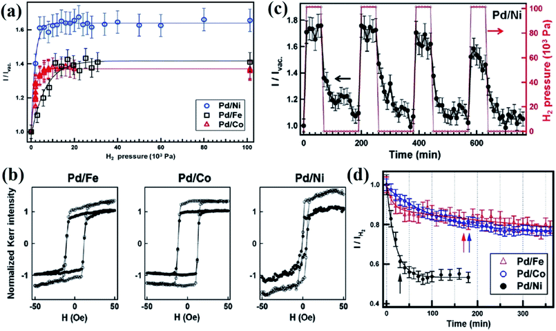
Lin et al.58 reported on the reversible change of MOKE in the Pd-covered magnetic thin films by controlling the H2 absorption. This absorption induced reversible MOKE enhancement in Pd-covered Fe, Co, and Ni thin films. As shown in Fig. 9a, the Kerr intensity drastically increased with H2 exposure and saturated at ∼5 × 10³ Pa, while Pd/Co and Pd/Fe were saturated at ∼8 × 10³ and ∼11 × 103 Pa, respectively. Fig. 9b indicates that H2 adsorption does not affect the magnetization processes of the magnetic films and the magneto-optical enhancement should originate from H2-induced change in the optical properties of Pd. Fig. 9c represents the reversibility of this H2 adsorption effect in the Pd/Ni bilayer. The Kerr intensity reached a saturation value within a few minutes and decreased slowly after the recovery of the vacuum. Fig. 9d indicates the time constant when the Kerr intensity recovered 80% of the H2-induced enhancement. These results indicate that the extinction angle of MOKE becomes shifted and correspondingly, the Kerr intensity is significantly increased after H2 exposure. This MOKE augmentation originates from the change in the optical properties of the hydrogenated Pd layer.
Hydrogenation-induced MOKE studies revealed that by tuning the thickness of the Pd layer in Pd/Fe bilayers, the MOKE extinction angle can be gradually shifted by 0.6%.66 The enhancement in the Kerr intensity reached 35–40% by exposure of 1 atm hydrogen with a different analyzer angle. Mudinepalli et al.67 investigated the annealing effect on the hydrogenation-related magnetic property changes of the Pd/Fe bilayer films. It was revealed that Pd–Fe inter diffusion, i.e., alloy formation occurred at about 700 K and the Hc increased by 2–3 times with an annealing temperature up to 700 K. Hydrogenation effect was observed in the 710 K annealed sample with an increase in the in-plane Hc by 10% when the hydrogen pressure was above 200 mbar. With further annealing in the range of 740–800 K, the hydrogenation effect on Hc became nearly unobservable. Hydrogenation induced changes in the magnetic properties of the Fe–V nanoclusters and the bilayer films were investigated by the MOKE effect.24,68,69 It was revealed that the lattice constant and electronic properties of the vanadium-intermediated nanoclusters get modified by the hydrogen content, which directly influences the exchange coupling between the Fe nanostructures.68 Hsu et al.25 revealed that by selecting a suitable Pd thickness under the application of a magnetic field perpendicular to the easy axis of the bottom Fe layer, two well-splitted hysteresis loops with almost zero Kerr remanence can be obtained. The split of the hysteresis into two double loops is reported to be due to the 90° rotation of the top-Fe moment. By the exposure to hydrogen gas, the separation of the two minor loops was increased due to the formation of the Pd-hydride formed in the space layer. These investigations suggested that the Pd space layer mediated the magnetic interlayer coupling, which was sensitive to the hydrogen atmosphere, demonstrating Fe/Pd multilayers as an emerging material for a great magnetic resistance (GMR)-type sensor for H2 sensing.
2.4 FMR-based magnetic gas sensors
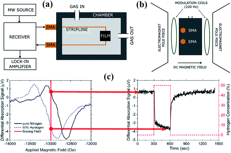 | ||
| Fig. 10 Schematic illustration of the (a) FMR based gas sensor set up. (b) The chamber during measurement mounted between the poles of the electromagnet and the modulation coils. (c) Typical FMR spectra in the presence of nitrogen and H2 gas used to evaluate the sensor response. Reprinted with permission from ref. 77. Copyright (2017) Elsevier. | ||
The observed decrease in the resonance linewidth upon hydrogen charging for the Pd/Co bilayer film is explained by different possible contributions.76 One of the proposed effects is the spintronic effect of spin pumping at the interface due to the Pd layer.78 Upon hydrogen absorption, the conductivity of the Pd layer decreases, which results in a reduction in the spin pumping contribution to the resonance linewidth of FMR. The second contribution is proposed to be due to the variation in the Gilbert damping by the variation in the d–d hybridization at the interface.79,80 The third effect is believed to be due to eddy current losses at the resonance linewidth upon the reduction in the conductivity of the Pd layer.81,82 It is further demonstrated that the nano-patterning of the Pd/Co/Pd multilayered films results in a higher sensitivity to hydrogen gas and a much faster desorption rate without any applied external magnetic field.17
Recently, Causer et al.83 reported the interface-resolved materials characterization of Co (5 nm)/Pd (8 nm) magnetic H2 gas sensors in operando during hydrogen gas cycling and revealed the physical mechanism. Combined observations from interface-sensitive polarized neutron reflectometry (PNR) with in situ FMR measurements and density functional theory (DFT) calculations revealed that the spin polarization at the Fermi level of the Co/Pd structure gets modified upon H2 gas absorption (Fig. 11). FMR experiments showed a broad spectrum that reached resonance at an applied field of Hres = 819 Oe, whereas H2 absorption changed the resonance position to a reduced field of Hres = 707 Oe. DFT calculations supported the experimental findings and indicated that an out-of-plane expansion of the Pd layer (∼7.5% increase in the overall thickness of the Pd layer upon exposure to H2) and electronic modification of the Co/Pd film occurs due to H2 absorption change in the total density of states and modified spin polarization at the Fermi level was observed, which provides insights to the magnetic H2 sensing based on FMR (Fig. 11g–i).
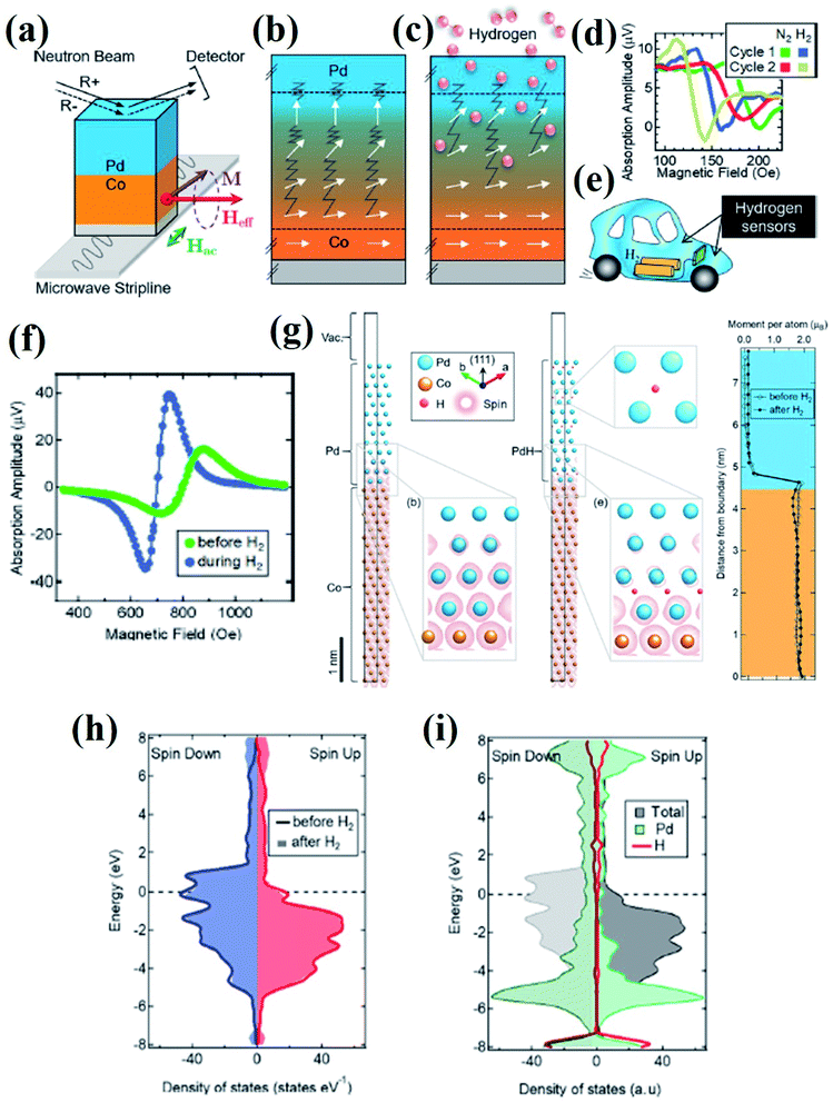 | ||
| Fig. 11 In operando study of the FMR based hydrogen sensing using Co/Pd film. (a) Polarized neutron reflectometry (PNR) with an in situ FMR experimental setup (b) before and (c) during exposure to H2 gas demonstrating the modification of Co/Pd interface with the change in the projection of the FM spins into the film plane. (d) FMR spectra of a Co (5 nm)/Pd (15 nm) film displaying excellent cycling ability between the first and second consecutive exposures to hydrogen gas. (e) Schematic illustration of the application of H2 sensor in hydrogen fuel cell vehicle. (f) Field-resolved FMR spectra of the Co/Pd film during hydrogen gas cycling. (g) DFT calculations of the theoretical Co/Pd thin-film structure. Electronic density of states determined from DFT calculations for a theoretical Co/Pd thin-film structure. (h) Total spin-resolved density of states and (i) site-projected density of states, including the projected density of states contributed by a hydrogen and a Pd site. Reprinted with permission from ref. 83. Copyright (2019) American Chemical Society. | ||
2.5 Magnetostatic surface spin-wave (MSSW) oscillator type magnetic gas sensors
| f = f0 + δFSL = γ(HB + HSL) + γδHSL | (16) |
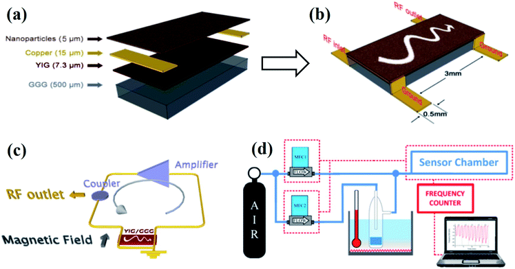 | ||
| Fig. 12 Two-port magnetostatic surface wave (MSSW) delay line for magnetic gas sensing. (a) Composition layer, (b) geometrical parameters, (c) schematic of the oscillator controller MSSW device, (d) schematic of the magnetic gas sensing instrumentation and set-up used for the measurements. Reprinted with permission from ref. 26. Copyright (2015) Royal Society of Chemistry. | ||
The observed frequency shifts in the presence of gas vapors were attributed due to the changes in the magnetic properties of the CuFe2O4 nanoparticles. Further, Matatagui et al.84 investigated the comparative magnetic gas sensing performance of magnetic nanoparticle layers of CuFe2O4, MnFe2O4, ZnFe2O4, and CoFe2O4 (Fig. 13). Typical frequency response curves in the presence of VOCs, dynamic response, and the response change in different concentrations of gas vapors are provided in Fig. 13. The applications of MSSW type sensors are mainly limited due to the complicated setup and high cost.26,84 The advantageous features of these emerging magnetic gas sensors along with their key limitations are summarized in Table 1.
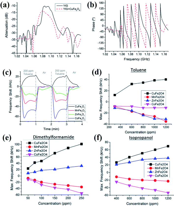 | ||
| Fig. 13 (a and b) Frequency response of the MSSW-based magnetic gas sensor device before and after being coated with CuFe2O4 nanoparticles. (c) Response of the magnetic gas sensors based on spinel oxides for 200 ppm toluene at room temperature. The response of the magnetic sensors at different concentrations of (d) toluene, (e) dimethylformamide, and (f) isopropanol. Reprinted with permission from ref. 84. Copyright (2017) Elsevier. | ||
| Type of sensor | Advantages | Disadvantages |
|---|---|---|
| Magnetization change | 1. Highly sensitive to reducing or oxidizing gases | 1. High cost |
| 2. Challenging set-up optimization | ||
| Hall effect | 1. Weakly dependent on the analyte gas concentration in air | 1. Sensitivity depends on the operating temperature |
| 2. High surface area of the nanostructures favors the enhanced sensing performance | 2. Sensing response depend on the type (p- or n-type) of material | |
| 3. Performance is highly dependent on the film composition, thickness, and field of operation | ||
| Kerr effect | 1. High surface-sensitive properties | 1. Tricky analyzer angle adjustment |
| 2. Signal is not affected by the paramagnetic and diamagnetic contributions of the substrates | ||
| Ferromagnetic resonance (FMR) effect | 1. Improve the signal to noise ratio | 1. Proper adjustment of the magnetic field is needed |
| Magnetostatic surface spin wave oscillator (MSSW) | 1. Detects low concentration of gases | 1. High cost |
| 2. Accurately measures weak variations | 2. Multistep, complicated experimental setup | |
| 3. Good reproducibility |
3 Conclusion and future perspectives
We have reviewed the basic working principles, sensing mechanisms, and recent developments in magnetic gas sensing. Compared to their electrical property-based gas sensor counterparts, magnetic gas sensors have emerged as a more attractive candidate due to the following reasons. (i) No electrical contacts are needed to detect the gas, which lowers the risk of explosion due to fire when used in hydrogen-powered vehicles or in the presence of reactive chemicals or pollutants, (ii) the magnetic response is much faster compared to chemiresistive sensors, (iii) the working temperature of the sensors can be room temperature and it can be tuned to a very low or very high temperature by choosing magnetic materials with different Curie temperature (Tc). We have provided a detailed description on the several effects used for magnetic gas sensing, which includes the Hall effect, Kerr effect, magnetization, spin change effects ferromagnetic resonance (FMR) effect, magneto-plasmonic effect, and magneto-static spin-wave (MSW) effect are employed for magnetic gas sensing applications. We have also reviewed recent developments on different materials used for magnetic sensing, which includes powder, thin films, and nanomaterials with magnetic (ferro- and antiferromagnets), diluted magnetic semiconducting (DMS) properties, and Pd alloys with transition metals (Co, Ni, Fe, Mn, and Cu). Subsequently, we have discussed the origin of enhanced sensitivity and working principles of magnetic gas sensors.Although magnetic gas sensors based on different materials perform well, there is still a long way to go before it can be applied for further practical applications and there is plenty of room to investigate the gas sensing performances of several emerging advanced magnetic 2D materials. For example, black phosphorous, MXenes, and other groups of TMDs are not yet investigated for magnetic gas sensor device applications. Doping and modifying these 2D materials with magnetic materials can enable them to tune their magnetic properties for gas sensing applications. Tuning the number of layers and the modification of these 2D materials by different other approaches such as defect and vacancy engineering, alloying, intercalation, tuning the materials in x–y and z directions, and fabrication of heterostructures of 2D materials with a different orientation, by which the properties of the materials can be further tuned to achieve enhanced magnetic gas sensing performance. More investigations are needed to inspire efforts to address challenges such as a compatible and low-power operation in different interfering environments, stability, selectivity, speed, and multifunctionality. Piezotronic and piezophototronic effects are emerging areas in gas sensors research in recent years, which may be applied to magnetic gas sensor devices by choosing appropriate magnetic materials. Further, the fabrication of flexible, wearable, and self-powered gas sensor design is another important research area that needs to be explored in magnetic gas sensor devices. Further, research in this field by using active materials with high mechanical flexibility will create new dimensions and possibilities in the area of wearable magnetic gas sensor systems. In this regard, novel emerging materials in magnetic gas sensor device configuration and technologies need to be explored.
Conflicts of interest
The authors declare no conflict of interest.Acknowledgements
This work was financially supported by the Department of Science and Technology (DST)-SERB Early Career Research project (Grant No. ECR/2017/001850), DST-Nanomission (DST/NM/NT/2019/205(G) and DST/TDT/SHRI-34/2018), Karnataka Science and Technology Promotion Society (KSTePS/VGST-RGS-F/2018-19/GRD NO. 829/315).References
- J. Zhang, X. Liu, G. Neri and N. Pinna, Adv. Mater., 2016, 28, 795–831 CrossRef CAS.
- F. L. Meng, Z. Guo and X. J. Huang, Trends Anal. Chem., 2015, 68, 37–47 CrossRef CAS.
- S. Yuan and S. Zhang, J. Semicond., 2019, 40, 111608 CrossRef CAS.
- P. Tyagi, A. Sharma, M. Tomar and V. Gupta, Sens. Actuators, B, 2016, 224, 282–289 CrossRef CAS.
- N. Joshi, T. Hayasaka, Y. Liu, H. Liu, O. N. Oliveira and L. Lin, Microchim. Acta, 2018, 185, 213 CrossRef.
- S. Kumar, V. Pavelyev, P. Mishra, N. Tripathi, P. Sharma and F. Calle, Mater. Sci. Semicond. Process., 2020, 107, 104865 CrossRef CAS.
- P. K. Kannan, D. J. Late, H. Morgan and C. S. Rout, Nanoscale, 2015, 7, 13293–13312 RSC.
- G. Lin, D. Makarov and O. G. Schmidt, Lab Chip, 2017, 17, 1884–1912 RSC.
- R. Ciprian, C. Baratto, A. Giglia, K. Koshmak, G. Vinai, M. Donarelli, M. Ferroni, M. Campanini, E. Comini, A. Ponzoni and G. Sberveglieri, RSC Adv., 2016, 6, 42517–42521 RSC.
- A. Z. Sadek, W. Wlodarski, K. Shin, R. B. Kaner and K. Kalantar-Zadeh, Nanotechnology, 2006, 17, 4488 CrossRef CAS.
- J. Hodgkinson and R. P. Tatam, Meas. Sci. Technol., 2012, 24, 012004 CrossRef.
- E. Comini, G. Faglia and G. Sberveglieri, Solid State Gas Sensing, Springer Science & Business Media, 2008 Search PubMed.
- C. S. Rout, D. Late and H. Morgan, Fundamentals and Sensing Applications of 2D Materials, Woodhead Publishing, 1st edn, 2019 Search PubMed.
- J. Van den Broek, S. Abegg, S. E. Pratsinis and A. T. Güntner, Nat. Commun., 2019, 10, 1–8 CrossRef CAS.
- A. Gerber, G. Kopnov and M. Karpovski, Appl. Phys. Lett., 2017, 111, 143505 CrossRef.
- J. Y. Liang, Y. C. Pai, T. N. Lam, W. C. Lin, T. S. Chan, C. H. Lai and Y. C. Tseng, Appl. Phys. Lett., 2017, 111, 023503 CrossRef.
- C. Lueng, P. Lupo, P. J. Metaxas, M. Kostylev and A. O. Adeyeye, Adv. Mater. Technol., 2016, 1, 1600097 CrossRef.
- R. C. Singh, M. P. Singh and H. S. Virk, in Solid State Phenomena, ed. H. S. Virk, Trans Tech Publications Ltd., 2013, vol. 201, pp. 131–158 Search PubMed.
- R. Malik, V. K. Tomer, Y. K. Mishra and L. Lin, Appl. Phys. Rev., 2020, 7, 021301 CAS.
- L. Ge, X. Mu, G. Tian, Q. Huang, J. Ahmed and Z. Hu, Front. Chem., 2019, 7, 839 Search PubMed.
- J. Y. Lin, X. L. He, A. J. Zhang, S. H. Huang and Z. X. Chen, J. Mater. Sci.: Mater. Electron., 2019, 30, 20696–20702 CrossRef CAS.
- R. Ciprian, P. Torelli, A. Giglia, B. Gobaut, B. Ressel, G. Vinai, M. Stupar, A. Caretta, G. De Ninno, T. Pincelli and B. Casarin, RSC Adv., 2016, 6, 83399–83405 RSC.
- C. Lueng, P. Lupo, T. Schefer, P. J. Metaxas, A. O. Adeyeye and M. Kostylev, Int. J. Hydrogen Energy, 2019, 44, 7715–7724 CrossRef CAS.
- D. O. Ignatyeva, G. A. Knyazev, P. O. Kapralov, G. Dietler, S. K. Sekatskii and V. I. Belotelov, Sci. Rep., 2016, 6, 28077 CrossRef CAS.
- C. C. Hsu, P. C. Chang, Y. H. Chen, C. M. Liu, C. T. Wu, H. W. Yen and W. C. Lin, Sci. Rep., 2018, 8, 1–2 CrossRef.
- D. Matatagui, O. V. Kolokoltsev, N. Qureshi, E. V. Mejía-Uriarte and J. M. Saniger, Nanoscale, 2015, 7, 9607–9613 RSC.
- P. T. Moseley, Sens. Actuators, B, 1992, 6, 149–156 CrossRef CAS.
- R. F. Taylor and J. S. Schultz, Handbook of Chemical and Biological Sensors, CRC Press, 1st edn, 1996 Search PubMed.
- A. Punnoose, K. M. Reddy, J. Hays, A. Thurber and M. H. Engelhard, Appl. Phys. Lett., 2006, 89, 112509 CrossRef.
- A. Punnoose, K. M. Reddy, A. Thurber, J. Hays and M. H. Engelhard, Nanotechnology, 2007, 18, 165502 CrossRef.
- Y. Yong, X. Su, Q. Zhou, Y. Kuang and X. Li, Sci. Rep., 2017, 7, 1–2 CrossRef CAS.
- S. Impeng, A. Junkaew, P. Maitarad, N. Kungwan, D. Zhang, L. Shi and S. Namuangruk, Appl. Surf. Sci., 2019, 473, 820–827 CrossRef CAS.
- T. G. Glover, D. Sabo, L. A. Vaughan, J. A. Rossin and Z. J. Zhang, Langmuir, 2012, 28, 5695–5702 CrossRef CAS.
- K. Munbodh, F. A. Perez and D. Lederman, J. Appl. Phys., 2012, 111, 123919 CrossRef.
- K. Munbodh, F. A. Perez, C. Keenan, D. Lederman, M. Zhernenkov and M. R. Fitzsimmons, Phys. Rev. B: Condens. Matter Mater. Phys., 2011, 83, 094432 CrossRef.
- J. A. Ziman, Principle of the Theory of Solids, Cambridge University Press, Cambridge, 2nd edn, 1972 Search PubMed.
- A. Weidinger, D. Nagengast, C. Rehm, F. Klose and B. Pietzak, Thin Solid Films, 1996, 275, 48–53 CrossRef CAS.
- V. Uzdin, D. Labergerie, K. Westerholt, H. Zabel and B. Hjörvarsson, J. Magn. Magn. Mater., 2002, 240, 481–484 CrossRef CAS.
- F. Klose, C. Rehm, D. Nagengast, H. Maletta and A. Weidinger, Phys. Rev. Lett., 1997, 78, 1150 CrossRef.
- B. Hjörvarsson, J. A. Dura, P. Isberg, T. Watanabe, T. J. Udovic, G. Andersson and C. F. Majkrzak, Phys. Rev. Lett., 1997, 79, 901 CrossRef.
- V. Leiner, K. Westerholt, A. M. Blixt, H. Zabel and B. Hjörvarsson, Phys. Rev. Lett., 2003, 91, 037202 CrossRef CAS.
- E. M. Pugh, Phys. Rev., 1930, 36, 1503 CrossRef CAS.
- J. Y. Lin, W. M. Xie, X. L. He and H. C. Wang, Appl. Phys. A, 2016, 122, 801 CrossRef.
- J. W. Hammond and C. C. Liu, Sens. Actuators, B, 2001, 81, 25–31 CrossRef CAS.
- M. Epifani, A. Forleo, S. Capone, F. Quaranta, R. Rella, P. Siciliano and L. Vasanelli, IEEE Sens. J., 2003, 3, 827–834 CrossRef CAS.
- C. S. Rout, A. Govindaraj and C. N. Rao, J. Mater. Chem., 2006, 16, 3936–3941 RSC.
- J. Lin, Z. Chen, X. He and W. Xie, Int. J. Electrochem. Sci., 2017, 12, 6465–6476 CrossRef CAS.
- M. Shafiei, F. Hoshyargar, N. Motta and A. P. O'Mullane, Mater. Des., 2017, 122, 288–295 CrossRef CAS.
- S. S. Das, G. Kopnov and A. Gerber, J. Appl. Phys., 2018, 124, 104502 CrossRef.
- T. B. Flanagan and F. A. Lewis, Trans. Faraday Soc., 1959, 55, 1400–1408 RSC.
- K. Baba, U. Miyagawa, K. Watanabe, Y. Sakamoto and T. B. Flanagan, J. Mater. Sci., 1990, 25, 3910–3916 CrossRef CAS.
- T. Feng, Y. Xu and W. Zhang, Phys. Rev. Lett., 2017, 118, 173901 CrossRef.
- J. Hamrle, S. Blomeier, O. Gaier, B. Hillebrands, H. Schneider, G. Jakob, K. Postava and C. Felser, J. Phys. D: Appl. Phys., 2007, 40, 1563 CrossRef CAS.
- D. Lederman, Y. Wang, E. H. Morales, R. J. Matelon, G. B. Cabrera, U. G. Volkmann and A. L. Cabrera, Appl. Phys. Lett., 2004, 85, 615–617 CrossRef CAS.
- W. C. Lin, C. J. Tsai, H. Y. Huang, B. Y. Wang, V. R. Mudinepalli and H. C. Chiu, Appl. Phys. Lett., 2015, 106, 012404 CrossRef.
- M. G. Manera, G. Montagna, E. Ferreiro-Vila, L. González-García, J. R. Sánchez-Valencia, A. R. González-Elipe, A. Cebollada, J. M. Garcia-Martin, A. García-Martín, G. Armelles and R. Rella, J. Mater. Chem., 2011, 21, 16049–16056 RSC.
- D. Sander, W. Pan, S. Ouazi, J. Kirschner, W. Meyer, M. Krause, S. Müller, L. Hammer and K. Heinz, Phys. Rev. Lett., 2004, 93, 247203 CrossRef CAS.
- W. C. Lin, C. S. Chi, T. Y. Ho and C. J. Tsai, Thin Solid Films, 2013, 531, 487–490 CrossRef CAS.
- W. C. Lin, C. J. Tsai, B. Y. Wang, C. H. Kao and W. F. Pong, Appl. Phys. Lett., 2013, 102, 252404 CrossRef.
- W. C. Lin, C. J. Tsai, X. M. Liu and A. O. Adeyeye, J. Appl. Phys., 2014, 116, 073904 CrossRef.
- W. C. Lin, B. Y. Wang, H. Y. Huang, C. J. Tsai and V. R. Mudinepalli, J. Alloys Compd., 2016, 661, 20–26 CrossRef CAS.
- V. R. Mudinepalli, Y. C. Chen, P. C. Chang, C. C. Hsu, C. Y. Tsai, H. C. Chiu, C. T. Wu, H. W. Yen, S. J. Shih and W. C. Lin, J. Alloys Compd., 2017, 695, 2365–2373 CrossRef CAS.
- P. C. Chang, Y. C. Chen, C. C. Hsu, V. R. Mudinepalli, H. C. Chiu and W. C. Lin, J. Alloys Compd., 2017, 710, 37–46 CrossRef CAS.
- P. C. Chang, C. M. Liu, C. C. Hsu and W. C. Lin, Sci. Rep., 2018, 8, 1–3 CrossRef.
- X. Ke, G. J. Kramer and O. M. Løvvik, J. Phys.: Condens. Matter, 2004, 16, 6267 CrossRef CAS.
- W. C. Lin, C. S. Chi, T. Y. Ho, C. J. Tsai, F. Y. Lo, H. C. Chuang and M. Y. Chern, J. Appl. Phys., 2012, 112, 063914 CrossRef.
- V. R. Mudinepalli, C. J. Tsai, Y. C. Chuang, P. C. Chang, N. Plusnin and W. C. Lin, Appl. Surf. Sci., 2016, 366, 38–45 CrossRef CAS.
- V. K. Valev, M. Di Vece, M. J. Van Bael, D. Grandjean, S. Decoster, A. Vantomme, T. Verbiest and P. Lievens, J. Appl. Phys., 2009, 105, 114907 CrossRef.
- D. Labergerie, C. Sutter, H. Zabel and B. Hjörvarsson, J. Magn. Magn. Mater., 1999, 192, 238–246 CrossRef CAS.
- B. N. Engel, C. D. England, R. A. Van Leeuwen, M. H. Wiedmann and C. M. Falco, Phys. Rev. Lett., 1991, 67, 1910 CrossRef CAS.
- C. Lueng, F. Zighem, D. Faurie and M. Kostylev, J. Appl. Phys., 2017, 122, 163901 CrossRef.
- A. Hirohata, H. Sukegawa, H. Yanagihara, I. Žutić, T. Seki, S. Mizukami and R. Swaminathan, IEEE Trans. Magn., 2015, 51, 1 Search PubMed.
- D. Weller, Y. Wu, J. Stöhr, M. G. Samant, B. D. Hermsmeier and C. Chappert, Phys. Rev. B: Condens. Matter Mater. Phys., 1994, 49, 12888 CrossRef CAS.
- C. Chappert and P. Bruno, J. Appl. Phys., 1988, 64, 5736–5741 CrossRef CAS.
- S. Okamoto, O. Kitakami and Y. Shimada, J. Magn. Magn. Mater., 2002, 239, 313–315 CrossRef CAS.
- C. S. Chang, M. Kostylev and E. Ivanov, Appl. Phys. Lett., 2013, 102, 142405 CrossRef.
- C. Lueng, P. J. Metaxas, M. Sushruth and M. Kostylev, Int. J. Hydrogen Energy, 2017, 42, 3407–3414 CrossRef CAS.
- J. M. Shaw, H. T. Nembach and T. J. Silva, Phys. Rev. B: Condens. Matter Mater. Phys., 2012, 85, 054412 CrossRef.
- S. Mizukami, E. P. Sajitha, D. Watanabe, F. Wu, T. Miyazaki, H. Naganuma, M. Oogane and Y. Ando, Appl. Phys. Lett., 2010, 96, 152502 CrossRef.
- K. Ando, S. Takahashi, J. Ieda, H. Kurebayashi, T. Trypiniotis, C. H. Barnes, S. Maekawa and E. Saitoh, Nat. Mater., 2011, 10, 655–659 CrossRef CAS.
- E. Lee, J. M. Lee, J. H. Koo, W. Lee and T. Lee, Int. J. Hydrogen Energy, 2010, 35, 6984–6991 CrossRef CAS.
- C. Aruta, G. Balestrino, A. Tebano, G. Ghiringhelli and N. B. Brookes, Europhys. Lett., 2007, 80, 37003 CrossRef.
- G. L. Causer, M. Kostylev, D. L. Cortie, C. Lueng, S. J. Callori, X. L. Wang and F. Klose, ACS Appl. Mater. Interfaces, 2019, 11, 35420–35428 CrossRef CAS.
- D. Matatagui, O. V. Kolokoltsev, N. Qureshi, E. V. Mejía-Uriarte, C. L. Ordoñez-Romero, A. Vázquez-Olmos and J. M. Saniger, Sens. Actuators, B, 2017, 240, 497–502 CrossRef CAS.
- J. P. Castéra and P. Hartemann, Circuits, Syst. Signal Process., 1985, 4, 181–200 CrossRef.
| This journal is © The Royal Society of Chemistry 2021 |


