
 Open Access Article
 This Open Access Article is licensed under a Creative Commons Attribution-Non Commercial 3.0 Unported Licence
The formation principle of micro-droplets induced by using optical tweezers†
Cong
Zhai
 ab,
Chunguang
Hu
*ab,
Shuai
Li
ab,
Yanhua
Ma
ab,
Yajing
Zhang
ab,
Tong
Guo
ab,
Hongbin
Li
ac and
Xiaotang
Hu
ab
ab,
Chunguang
Hu
*ab,
Shuai
Li
ab,
Yanhua
Ma
ab,
Yajing
Zhang
ab,
Tong
Guo
ab,
Hongbin
Li
ac and
Xiaotang
Hu
ab
aState Key Laboratory of Precision Measuring Technology and Instruments, Tianjin University, Tianjin 300072, China. E-mail: cghu@tju.edu.cn
bNanchang Institute for Microtechnology of Tianjin University, Tianjin 300072, China
cDepartment of Chemistry, University of British Columbia, 2036 Main Mall, Vancouver BC V6T 1Z1, Canada
First published on 16th November 2020
Abstract
Utilizing droplets as micro-tools has become a valuable method in biology and chemistry. In previous work, we have demonstrated a novel droplet generation–manipulation method in a conventional optical tweezer system. Here, a further study of the droplet composition and its formation principle is performed. First, it is proved through Raman spectra that the principal component of the droplets is HPO42− solution. Considering that the generated droplet size is at the μm level, we have adopted a variety of methods in experiments to reduce external interference. Second, using a confocal microscopic video camera, the growth process of the droplet is completely recorded in a common glass-based chamber. The finite element simulations help us to further understand that the droplet generation process using optical tweezers can be divided into two stages: “capture” caused by optical force field and “aggregation” induced by a photothermal phenomenon and thermal acceleration. Through these studies, the nature of the optical tweezer-generated droplets is revealed. As a general principle for the droplet generation, this method will provide inspiration and prospects in the fields of microfluidics and biophysics-chemistry.
Introduction
In early research, the method of aqueous compartments has been applied to control the dispersion and mixing of solutions in biological experiments.1 It can provide a compartment to isolate species and conduct quantitative studies, the same as micro-reactors.2 With the development of microfabrication, this method has evolved into sophisticated microfluidic technology and is widely applied in the micro-level biochemistry area.3,4 In particular, the creation and utilization of droplet technology provide a new form of compartmentalization, further improving the precision of microcosmic reactions and manipulation in chemical and physical research.5 This is significant in reducing external interference and improving the sensitivity and efficiency of microchemical reactions.6,7 The current fabrication processes of droplets are mainly focused on high-speed stirring,8 layer-by-layer assembly,9 and more complicated methods including membrane emulsification and interfacial polymerization.10,11 Such approaches generally rely on oil–water mixtures, which are easily stratified and difficult to achieve precise control for meeting the demands of precise transportation and manipulation unless utilizing special microfluidic chips.12 Concerning this problem, optical tweezers were introduced and a novel method for the generation of controlled micro-droplets was developed in our previous research.13In fact, this droplet generation method was discovered accidentally in an optical tweezer experiment. Taking advantage of high-precision controllability of optical tweezers,14,15 this method can generate, manipulate, and transport micro-droplets in a mixture of inorganic phosphate buffer saline (PBS) and isopropanol (IPA). Although the necessary conditions of droplet generation have been discussed in previous research, there are still basic principles unknown, such as the droplet composition and its formation mechanism. Revealing these fundamental problems will help us to understand the physical and chemical nature of optical tweezer based droplet generation. But there are several challenges. For example, the electrochemical analysis of micro-droplets is obstructed by the tiny size of the droplet and the space of microfluidic chips. It is also disturbed by the strong noise signals from the surrounding solvent. In addition, an advanced measurement with a precise and flexible operation is desired for the investigation of the droplet formation process.
In this paper, we focused on the nature of the micro-droplets and verified the formation process. First, a confocal Raman microscope was utilized to determine the fingerprint spectra of the generated droplet. Via principal component analysis (PCA) of the spectra of droplets and raw components, the main composition of the droplets was found to be HPO42−, a phosphate solution ionized by Na2HPO4 in PBS. In order to visualize the formation process, a microfluidics design for the sample cell and a video camera were applied, and the finite difference time domain (FDTD) method was applied to simulate the effects of thermodynamic field and optical force field induced by highly focused optical tweezers. The simulation results show that multiple physical fields are the key factor for the generation of droplets. Finally, by combining the experimental phenomena with theoretical analysis, we propose an explanation for the physical mechanism of the droplet formation.
Experimental
Materials
In this study, isopropanol (IPA) and inorganic phosphate buffer saline (PBS) are mixed together as raw materials. IPA is a kind of organic solvent, widely used in chemical and pharmaceutical industries. PBS is mainly composed of ultrapure water and several salt components, including disodium hydrogen phosphate (Na2HPO4), sodium chloride (NaCl), potassium chloride (KCl) and potassium dihydrogen phosphate (KH2PO4). As an aqueous buffer, PBS is often used to maintain the pH value for biological samples because of its certain stability in chemical reactions.16 Since IPA can increase the chemical affinity between the separated phases and does not chemically react with PBS basically, the mixed solution will not be stratified like the oil–water solution under normal circumstances.17,18Studies suggest that the deformability of the droplet could be affected by the salinity of the aqueous solution,19 thus the volume ratio of IPA to PBS could directly influence the efficiency of the optical tweezer based droplet generation. To meet the consistency of the experiment, we select the same volume ratio consistent with the previous study (4![[thin space (1/6-em)]](https://www.rsc.org/images/entities/char_2009.gif) :1 for IPA:PBS).13 Therefore, the 1 ml of PBS is first diluted with 4 ml of high-purity IPA, and subsequently loaded into the injector as the typical raw aqueous sample in this study. Apart from these, no other ingredients are used.
:1 for IPA:PBS).13 Therefore, the 1 ml of PBS is first diluted with 4 ml of high-purity IPA, and subsequently loaded into the injector as the typical raw aqueous sample in this study. Apart from these, no other ingredients are used.
Optical tweezer system
The experimental setup is shown in Fig. 1a. It mainly consists of a laser control module, microscope system, and sample stage. For the laser control module, an ultra-stable fibre-coupled laser (J20I-BL-106C, SpectraPhysics, 5 W) with a wavelength of 1064 nm is installed as the adjustable main light source to generate optical traps; a set of piezo rotation mounts with polarizing films is utilized for modulating the laser power; and a two-axis piezoelectric mirror (PM, MTA2X HS, Mad City Labs) is set to control the trap position. The microscope is used to focus the laser and generate optical trapping force, by using an objective (60×, NA = 1.2). The second light source (780 nm) for observation emitted from Kohler Illumination passes through the condenser (60×, NA = 1.4) and illuminates the sample chamber, which mainly consists of two coverslips. On the other side of the microscope lens, a video charge-coupled device (CCD, DCC1545M, 60 fps, Thorlabs) behind a dichroic mirror (DM) is utilized to observe and record the real-time circumstances in the sample chamber.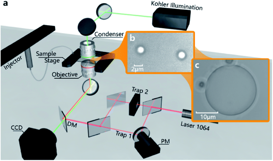 | ||
| Fig. 1 Schematic of the conventional optical tweezer system and images from a video camera. (a) is the schematic diagram of the optical path of the used optical tweezer system, trap 1 and trap 2 are capable to control the horizontal position of two optical traps; (b) shows two small droplets separately generated under two laser traps; (c) is a giant droplet generated by a single laser trap. | ||
After turning on the laser, the laser beam is emitted through the objective and focused in the centre of the sample chamber, which is held on a precision displacement platform by using a fixing bracket. As shown in Fig. 1b and c, the droplets will appear under the irradiations of the highly focused lasers when the raw sample is injected into the sample chamber by using a catheter (the detailed structure of the sample chamber is shown in Fig. S1 in the ESI†). The sum of droplets depends on the number of active light traps, and the size of the droplets relies on the amount of salt solution injected into the sample chamber. In particular, the two little droplets can converge into one large droplet easily if they are close enough. This means that the generated droplets entirely consist of liquid, bringing more control possibilities to the novel application of droplets. In order to reveal the droplet formation process simply and clearly, the subsequent experiments and analysis are based on a single optical trap.
Results and discussion
Composition analysis of droplets
To clarify the main components of the generated droplets, we generate a large-scale droplet (>100 μm in diameter) in the sample chamber by prolonged irradiation time, then move the bottom of the chamber towards the optical trap by raising the precision displacement platform until the generated droplet is adsorbed on the glass surface (as shown in Fig. 2c). This is beneficial for subsequent observations by fixing the generated droplet in a specific position. Considering that the scale of the generated droplet is still at μm-level, the chemometrics and gas chromatography cannot be applied to such microscopic composition detection. In this case, spectral detection is more suitable because a microscope module can precisely focus the light on targets with a microscale detection space. However, the infrared spectroscopy technology is also unavailable because it is difficult to measure samples with water as the solvent,20 while water as a component of PBS probably participates in the formation of droplets. As a result, we finally chose a confocal Raman microscope (inVia reflex, Renishaw) to identify the main components among the generated droplets. The excitation laser wavelength and power are 785 nm and 40 mW, respectively. The scanning wavenumber range of the Raman shift is set to 100–3200 cm−1, and the exposure time is set to 10 s. The raw Raman spectrum of droplets is shown as red line in Fig. 2a. Since the light goes through the coverslip and the surrounding solvent and finally reaches the droplets for Raman measurements, the influence of the coverslip should be overcome. Their Raman spectrum was also measured as the blue line in Fig. 2a and the spectrum in Fig. 2b is the re-projected result by subtracting the coverslip's Raman spectrum from the measured raw Raman spectrum.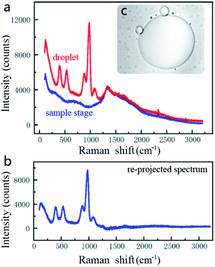 | ||
| Fig. 2 Raw spectra measured by using a Raman spectrometer and the processed spectrum of droplets. (a) The red line is a typical raw spectrum of droplets and the blue line is the signal of the sample chamber. (b) is the re-projected spectrum obtained by subtracting the spectrum of the sample chamber from the droplets' waveform. (c) Shows the large droplet attached on the coverslip. | ||
Fig. 3 lists the re-projected Raman spectra of the droplets and the re-projected spectra of IPA, Na2HPO4, KH2PO4, NaCl, and KCl, respectively. The last four are the specific components of PBS. As Fig. 3a–d show, there is a high similarity between the droplets, Na2HPO4 and KH2PO4. But the cumulative intensity of NaCl and KCl spectra is not obvious as shown in Fig. 3e and f. This is because for a molecule to exhibit a Raman effect, its electric dipole–electric dipole polarizability must change relative to the vibrational coordinate corresponding to the rovibronic state, which is almost non-existent in NaCl and KCl as well as metal ions in aqueous solution. In fact, it has been demonstrated in our previous study that the single NaCl or KCl solution cannot converge into droplets under the light trap because it cannot produce an effective relative refractive index with the medium solution. Hence, these two components will not be considered in a following analysis.
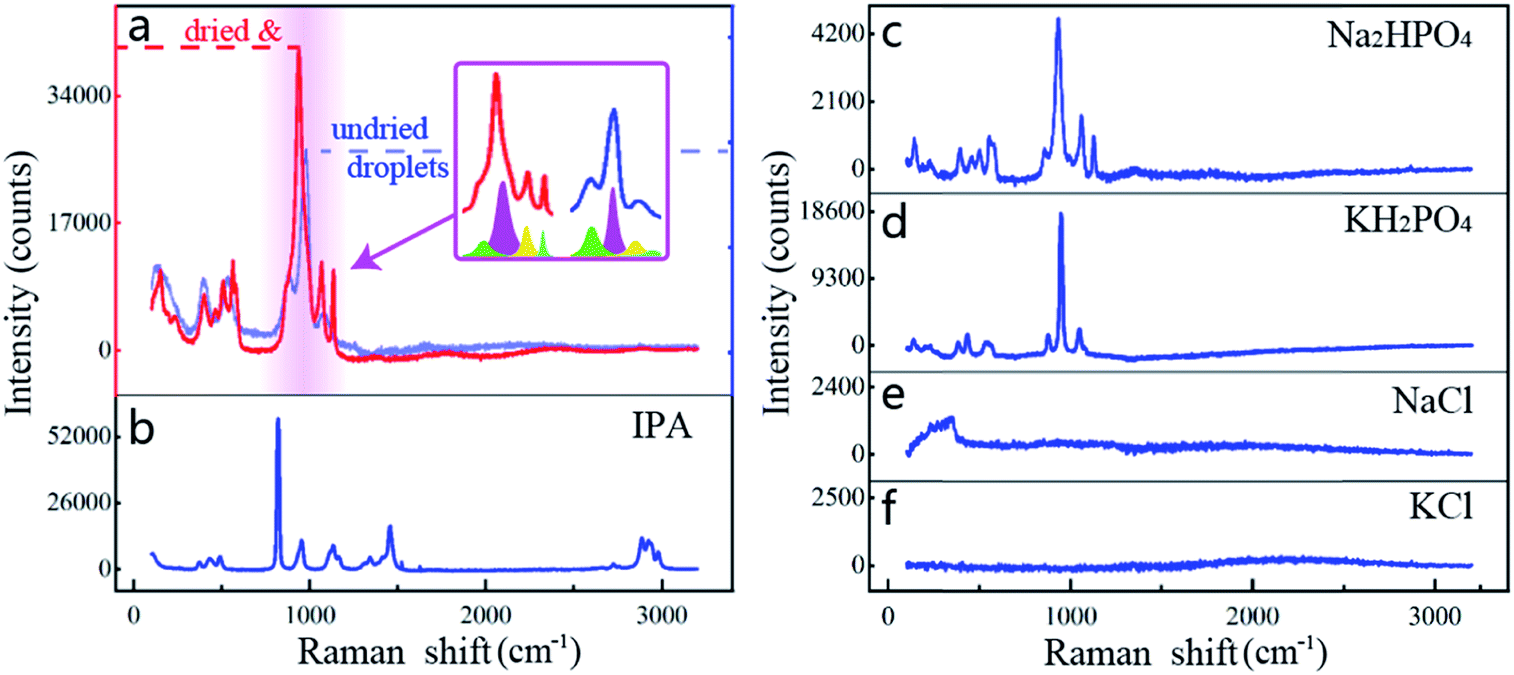 | ||
| Fig. 3 Comparison of Raman spectra of dried droplets and PBS. It is clear to see from (a) that the Raman peak of the undried droplets is less than one-third of the dried droplets. (b) Has a similarity with droplets, but it obviously contains a characteristic peak around 3000 cm−1. (c and d) Exhibit Na2HPO4 and KH2PO4 which have high similarity characteristics with droplets, but (e and f) show the significant difference of NaCl and KCl with droplets. | ||
Since a Raman spectrometer is used to measure scattered light of samples, the intensity in the liquid solution is relatively lower than crystal. In order to get a cleaner signal, the top coverslip is removed and the deposited droplets are dried in a dust-free environment for improving measurement sensitivity (Fig. S2c in the ESI†). Fig. 3a shows the spectral comparison of droplets before (blue line) and after drying (red line). Although there is a slight difference in the shape of the wave crests, the two spectra still represent the same thing. This is because the interatomic distance of the salt will be affected by the quantity of water when the concentration of the salt solution changes, and the bonding between atoms will change accordingly and reflect on the spectrum.21,22 In addition, it could be found through dividing the spectrum that the seemingly different waveforms are actually synthesized by four wavelets with the same Raman shift (more analyses are shown in Fig. S2†). This proves that the drying of droplets can significantly enhance the Raman intensity and sharpen the wave crests, while not affecting the corresponding Raman shift of the characteristic crests.
To further determine the droplet composition from the similar waves (Fig. 3b–d), PCA is implemented and the correlation between the spectra of phosphates, IPA, and droplets is quantified,23 as shown in Fig. 4 (the specific process is shown in the Appendix). The pairwise comparison method is first adopted to analyse the correlation between the droplets and all known components in PBS. In this process, the Raman spectra of the droplets and other components are compared respectively. For instance, the PCA in Fig. 4a involves the Raman spectra of droplets before and after drying. The abscissa indicates the correlation between all sample points from the spectra with the separated primary component, and the ordinate is another correlation with the secondary component. Because the spectra involved in this comparison represent the same component and the drying of the droplets does not significantly affect its spectral signature, the result shows that all the sample points converge with respect to the vertical axis, and the contribution rate of the primary separated eigenvectors (PC 1) reaches 97.8%. The same phenomenon is also shown in Fig. 4b. When the PCA method only involves the spectra of dried droplets and Na2HPO4, the correlation between them is also as high as 95.9%, which is much larger than that of the droplets between IPA, KH2PO4, respectively. To some extent, the phenomena in Fig. 4a and b can be regarded as the spectra participating in this PCA process representing the same substance.
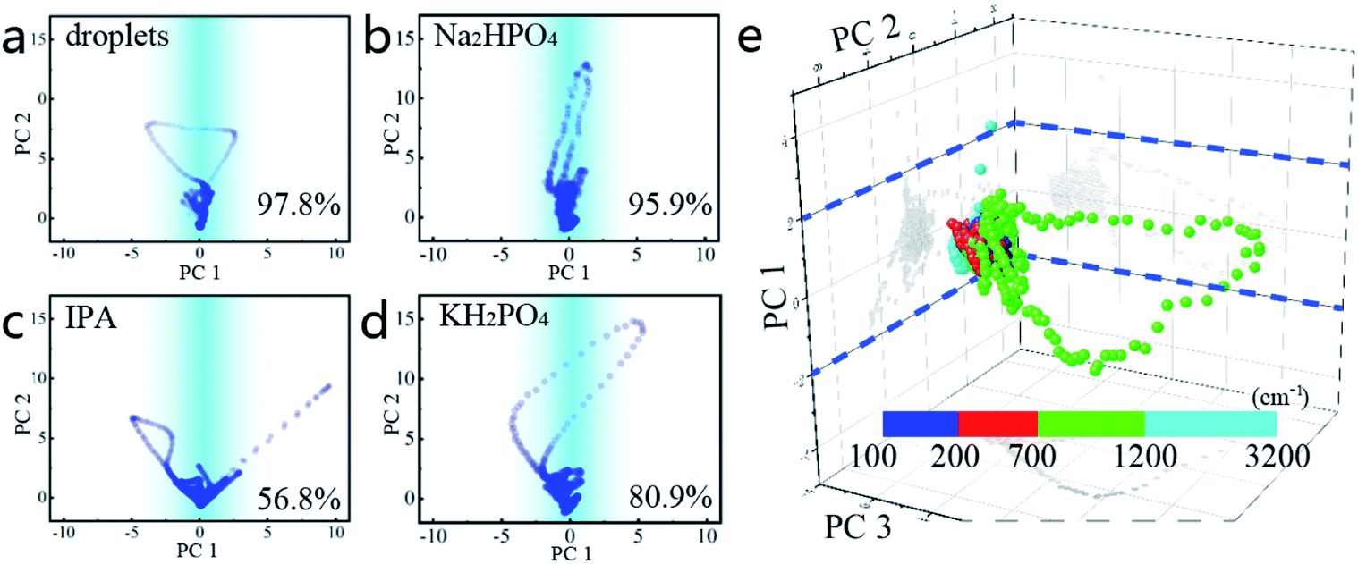 | ||
| Fig. 4 The analysis results of PCA in different dimensions. PC n represents the distribution of all data relative to the principal component x. (a–d) are the PCA between the spectra of dried droplets and normal droplets, Na2HPO4, IPA, and KH2PO4, separately. (e) is a routine PCA of droplets and all components of PBS. | ||
In addition, the correlation between the dried droplets and KH2PO4 is 80.9%, which is tremendously similar to the correlation between Na2HPO4 and KH2PO4 (81.4%, Fig. S3e in the ESI†). Since there are no other similar components in this experiment, it is concluded that Na2HPO4 is the principal component of the dried droplets.
Then, a routine PCA method for the droplets and all components of PBS is executed to determine the composition of the droplet from another aspect. In this process, an equal number of spectra for each component is chosen to constitute the multivariate arrays. Three effective feature vectors are separated through the dimension reduction of PCA, as shown in Fig. 4e. It is clear that all sample points also have a good aggregation on the plane corresponding to the PC 1 zero axes. The contribution ratios of the primary and secondary components to the entire eigenvector matrix are 81.6% and 15.5%. This significant difference in the contribution rate confirms another aspect that the main component of the dried droplets is Na2HPO4. Although HPO42− and H2PO4− in the solution will be affected by the concentration of hydrogen ions and undergo mutual conversion, an additional procedure shows that only Na2HPO4 solution could generate droplets (Fig. S3 in the ESI†). In this procedure, the pure solutions of NaCl, KCl, KH2PO4 and Na2HPO4 are separately tested under the same conditions without any spare component that could affect the pH value of the solution. The results show that only Na2HPO4 solution can generate droplets under the action of optical traps, further verifying that the main component of droplets is HPO42− solution.
Droplet generation process
To discover the principle of droplet formation, we use a video camera and shoot the complete formation process of a single droplet. Fig. 5a illustrates the sample chamber used to generate droplets. The raw sample is precisely injected under the drive of gas pressure.24 The light trap can realize the sub-nm minimum incremental motion at the junction of “T” structures, thus achieving the accurate and efficient droplet capture. Fig. 5b shows the vertical section plane of the microscope lens and sample chamber. The focal point of the laser beam is accurately positioned between the two coverslips of the sample chamber after the laser is turned on.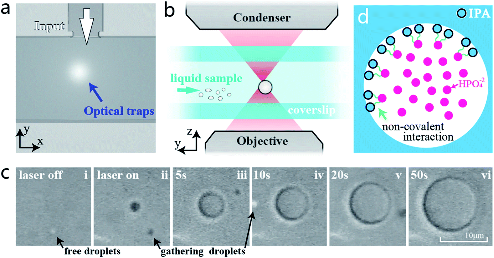 | ||
| Fig. 5 Schematic structure of the glass-based microfluidic chip and microscope system. (a) is an x–y plane of the microfluidic chip, which is assembled by using multiple sets of coverslips. An inverted “T” structure is set for mixing the sample and medium. (b) is the view perpendicular to the x-direction. The laser is focused by using the objective in the middle of the sample chamber and captures the droplets. (c) Shows a few frames in the generation process of a single large droplet after the laser is turned on. (d) is the conjecture of molecular structure in the tiny droplet interface. | ||
Fig. 5c shows the complete generation process of a droplet (Video 1 in the ESI†). Before the laser on, it is hard to perceive that there are tiny droplets free in the mixed solution. These droplets are probably caused by non-covalent interactions between the part phosphate groups of PBS and the hydroxyl groups of IPA during the mixing process. Such interactions can link molecules together like DNA strands.25 According to similarity–intermiscibility theory, the linked clusters may outline an interface between HPO42− solution and IPA, and shape spherical droplets under the action of liquid pressure (Fig. 5d). The additional dynamic light scattering (DLS, Zetasizer Nano ZS90, Malvern) measurements show that the average diameter of these original tiny droplets is about 900 nm, and the average polymer dispersity index (PDI) is 0.235. Normally, these tiny droplets are evenly distributed in the solution and hard to gather together. When the laser is turned on (frames i and ii), a few free tiny droplets near the light trap are immediately captured under the attraction of optical trapping force, converging into a larger droplet. Then, other tiny droplets from the surrounding solution are continually converged into this optically trapped droplet, as shown in frames iii–v. With the continuous injection of the raw sample, the trapped droplet gradually grows larger and is firmly controlled at the centre of the beam. In less than one minute, the size of the generated droplet has increased to more than 10 μm, showing a good growth rate. During this process, the growth can be stopped by interrupting the injection of raw samples, and the growth rate can also be affected by changing the laser intensity or the concentration of PBS to achieve the size controllability (the relevant research of droplet growth rate can be referred to in our previous research).13
A noticeable phenomenon during the formation process is that some tiny droplets are converged from a long-distance position which is already far beyond the scope of the optical trap. This means that the optical trapping force may be only one of the effects in the formation process of droplets. Therefore, we introduce a series of finite element simulations to reveal the influence of physical fields on the droplet generation process.
Simulation and analysis
From the previous experimental phenomenon it can be confirmed that owing to the low-absorption, the generated droplets have good light transmission and can be firmly trapped under the optical tweezers as the conventional transparent beads.26 To discover the principle of droplet generation, a ray optical analysis is first used to deduce the vector force on the generated droplet.27 When there is only one beam emitted from the objective and passes through the droplet, the laser will be refracted by the different refractive surfaces between the droplet and surrounding medium. Due to the particle nature of the light and conservation of momentum, the turned photons cause a gradient force opposite to the direction of the refraction, like the analysis in Fig. 6a. When the droplet deviates from the centre of the light trap, the focused laser will produce a combined force driving the droplet toward the centre of the light trap, just like the inchoate phase when the laser is turned on in Fig. 5c(ii). This process is realized by the particle nature of light, which is also one of the main principles of optical tweezer manipulation. Therefore, this photon-impact is defined as “capture”, the first step of droplet generation.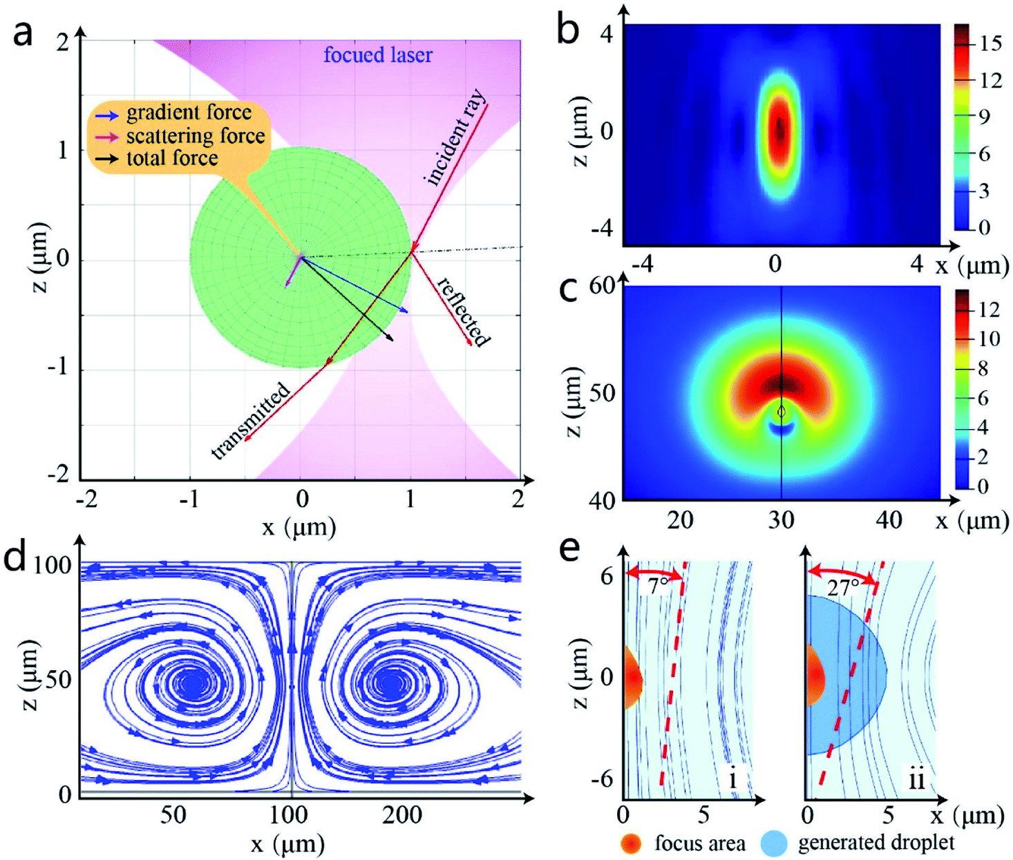 | ||
| Fig. 6 The FDTD simulation of objective (NA = 1.2) and the laminar flow simulation of the light trap in the sample chamber (COMSOL Multiphysics). (a) is the photon-impact force of a small size droplet simulated by ray optics. (b) is the power simulation of the narrowest point of the focused beam. (c) Describes the simulation of laminar flow velocity when liquid is heated by the light trap and (d) is the corresponding streamline simulation. (e) Exhibits the comparison of streamline simulation at the focal point before and after the droplet is formed. | ||
The effective “capture” area only exists at the centre of laser focus where there is a huge light intensity28,29 (Fig. 6b). However, the experiment shows that the tiny droplets still can continually flow into the formed droplet when the “capture” area is covered. This is consistent with the speculation in the previous section: the particle nature of light is only one of the elements in the generation of droplets. In addition to the light trap force, there must be other force fields to promote the growth of droplets. Considering the undulatory properties of light,30 the finite difference time domain (FDTD) method and “COMSOL” are operated to simulate the thermal energy of the highly focused beam31,32 and fluidity of liquid samples respectively.33 The reason is that under the laser irradiation, the radiation pressure may heat the liquid solution,34,35 affecting the laminar flow in the chamber.36 Due to the loss of laser in the optical path, the final power of the single optical trap is less than 600 mW in the sample chamber. According to the previous research, the centre temperature of the optical trap is estimated to be 30–40 °C.37
Fig. 6c shows the vertical view of the simulation of liquid flow velocity under focused laser light, and Fig. 6d illustrates the vortex flow trend caused by the radiation pressure at the x–z plane. Obviously, the radiation pressure engenders a series of little vortexes in the microfluidic chip and accelerates the circulation of the liquid to a great extent. That means the flow of tiny droplets from the surrounding solution is also accelerated toward the inside of the light beam with the liquid flow and fused with the generated droplet, which is exactly the same as the formation process in Fig. 5c(iii–vi). This process is defined as “aggregation”. Under the combined action of thermal acceleration and optical trapping force, these free droplets are immediately gathered together and shaped into a single larger droplet due to the liquid surface tension.38 Besides, the grown droplet can change the direction of heat transfer, as Fig. 6e shows, improving the liquid flow efficiency in the sample chamber.
Briefly, in the initial phase of droplet generation, the tiny droplets are mainly attracted and gathering into a larger droplet by the force field of the focused laser. This first gathering method of droplet formation is called “capture”. While the droplet size is larger than the scope of the light trap, the gradient of light intensity is completely wrapped by the liquid and cannot continue to capture the tiny droplet effectively. At this moment, the photothermal effect becomes dominant, heating the mixed solution to achieve thermal acceleration in the chamber. The other tiny droplets could still flow into the formed droplets under the drive of the small vortexes, making the formed droplet continue to grow. As the second stage of the droplet generation, this process is called “aggregation”. Although induced by different multiphysics, both “capture” and “aggregation” are necessary conditions for the droplet generation, completely consistent with the experimental phenomenon in Section 3.2.
From the above research, the essence of optical tweezer based droplet generation is revealed that under the comprehensive action of light traps, the tiny droplets can be gathered together to form the controlled droplets. Relying on the high-precision controllability of optical tweezers, the generated droplets have the capability to replace traditional beads in the transport of large molecules, or control the flow of the microchannels through their own tension. At present, the formation rationale of the tiny droplets, i.e. HPO42− droplets, in the raw sample has not been figured out clearly. But the studies on the interface between IPA and HPO42− solutions and the fusion process at the molecular level will be concentrated in future research.
Conclusions
In this work, the nature of the optical tweezer-generated droplets is obtained through the Raman spectrum analysis, and its formation principle is revealed by “generating” droplets in the sample chamber and simulation software. According to the measured Raman spectra and principal components analysis, HPO42− solution is the primary component of the droplets, which is consistent with our conjecture in the previous study. As the main component of PBS, HPO42− solution has a good light transmission and can produce a relative refractive index with IPA. Such characteristics make the optical tweezer-based droplet generation method more promising as advanced micro-control technology. After that, we completely analyse the droplet formation process through a versatile sample chamber with a microfluidic-like structure. The video camera records the complete generation process, and combined with the finite element simulation, the relatively complete principle is deduced. The formation and growth of droplets essentially are the “capture” and “aggregation” processes of tiny droplets coming from the raw sample. The droplet size can be precisely controlled at the μm-level by means of raw sample injection. With advantages in the excellent controllability and broad versatility, the optical tweezer-based droplet generation technology has great potential for application in composition detection, pharmaceutical transportation, and microfluidic operations, which is the focus of our future work.Appendix
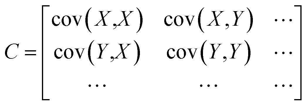
The typical PCA method uses an orthogonal transformation converting the hidden relatedness from multivariate arrays into the correlated variables, to reflect the actual principal components of original data sets.39 Firstly, to unify the quantification standards of different data arrays (X, Y…), the average value of each variable needs to be subtracted from each dataset to centre the data around the origin. Then, calculate the covariance matrix of the data, and get the eigenvalues and corresponding eigenvectors of the covariance matrix: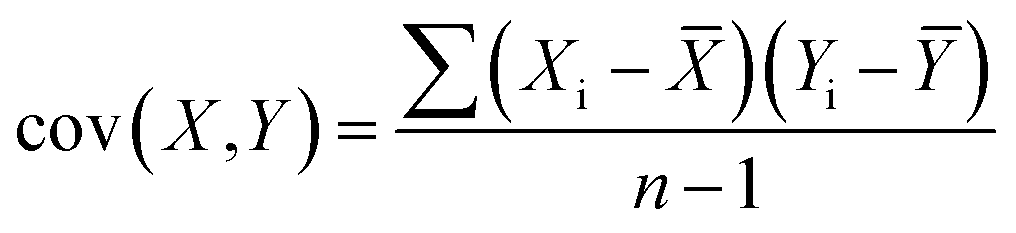 | (1) |
 | (2) |
After this process, each orthogonal eigenvector is normalized to a unit vector. The leading diagonal elements represent the variance of each axis and the counter-diagonal elements are the covariance matrix of different arrays, each unit eigenvector in the orthogonal can be interpreted as a recombinant axis for the fitted data. At this point, the preparation of the characteristic matrix of components is accomplished.
Next, before acting as the recombinant axis, the eigenvectors need to be sorted in descending order. Then the uniformly quantified data project onto the first recombinant axis which also is the largest, to constitute an eigenvectors matrix. If there are multiple crucial components in the original data arrays, it is necessary to calculate its contribution to the entire eigenvector matrix beginning from the largest eigenvector. When the sum contribution cannot reach the set threshold, choosing the eigenvector in turn and calculating the cumulative contribution until the total contribution reaches the threshold. In this process, the reformed eigenvectors matrix can be expressed as follows:
| F(m,k) = U(m,n) × K(n,k) | (3) |
In this formula, m is the number of total arrays n is the number of features in each component array, U(m,n) represents the matrix which unified the quantization standard, k is the number of selected eigenvalues when calculating the contribution, and K(n,k) is a matrix formed during this calculation.
Conflicts of interest
There are no conflicts to declare.Acknowledgements
The authors thank Professor Li Qifeng for the confocal Raman microscope and valuable discussion. This work was supported by the National Key Research and Development Program of China [grant number 2016YFB1102203]; National Natural Science Foundation of China [grant number 61927808].References
- D. S. Tawfik and A. D. Griffiths, Nat. Biotechnol., 1998, 16, 652–656 CrossRef CAS.
- A. S. Utada, E. Lorenceau, D. R. Link, P. D. Kaplan, H. A. Stone and D. A. Weitz, Science, 2005, 308, 537–541 CrossRef CAS.
- C. N. Baroud, F. Gallaire and R. Dangla, Lab Chip, 2010, 10, 2032–2045 RSC.
- P. B. Umbanhowar, V. Prasad and D. A. Weitz, Langmuir, 2000, 16, 347–351 CrossRef CAS.
- C. N. Baroud, M. Robert De Saint Vincent and J. P. Delville, Lab Chip, 2007, 7, 1029–1033 RSC.
- C. Jiu-Sheng and J. Jia-Huan, Chin. J. Anal. Chem., 2012, 40, 1293–1300 Search PubMed.
- A. B. Theberge, F. Courtois, Y. Schaerli, M. Fischlechner, C. Abell, F. Hollfelder and W. T. S. Huck, Angew. Chem., Int. Ed., 2010, 49, 5846–5868 CrossRef CAS.
- M. A. Pechenkin, H. Möhwald and D. V. Volodkin, Soft Matter, 2012, 8, 8659–8665 RSC.
- Q. Xu, M. Nakajima, S. Ichikawa, N. Nakamura and T. Shiina, Innovative Food Sci. Emerging Technol., 2008, 9, 489–494 CrossRef.
- V. Freger, Langmuir, 2003, 19, 4791–4797 CrossRef CAS.
- Q. Zhao, B. Han, Z. Wang, C. Gao, C. Peng and J. Shen, Nanomedicine, 2007, 3, 63–74 CrossRef CAS.
- Z. Z. Chong, S. H. Tan, A. M. Gañán-Calvo, S. B. Tor, N. H. Loh and N. T. Nguyen, Lab Chip, 2016, 16, 35–58 RSC.
- S. Li, C. Hu, X. Gao, G. Ma, H. Li, X. Hu and X. Hu, Appl. Phys. Express, 2019, 12, 10–14 Search PubMed.
- Q. He, X. Chen, Y. He, T. Guan, G. Feng, B. Lu, B. Wang, X. Zhou, L. Hu and D. Cao, Biosens. Bioelectron., 2019, 129, 107–117 CrossRef CAS.
- Y. Shen, X. Wang, Z. Xie, C. Min, X. Fu, Q. Liu, M. Gong and X. Yuan, Light: Sci. Appl., 2019, 8, 90 CrossRef.
- G. Bennett, J. Hazard. Mater., 1992, 3(30), 373 Search PubMed.
- M. Z. Shahid, M. R. Usman, M. S. Akram, S. Y. Khawaja and W. Afzal, J. Chem. Eng. Data, 2017, 4(62), 1198–1203 CrossRef.
- K. Schrödter, G. Bettermann, T. Staffel, F. Wahl, T. Klein and T. Hofmann, in Ullmann's Encyclopedia of Industrial Chemistry, 2008 Search PubMed.
- G. Bolognesi, A. Hargreaves, A. D. Ward, A. K. Kirby, C. D. Bain and O. Ces, RSC Adv., 2015, 5(11), 8114–8121 RSC.
- L. Cabernard, L. Roscher, C. Lorenz, G. Gerdts and S. Primpke, Environ. Sci. Technol., 2018, 52(22), 13279–13288 CrossRef CAS.
- M. K. Cerreta and K. A. Berglund, J. Cryst. Growth, 1987, 4(84), 577–588 CrossRef.
- E. H. Majzoub, K. F. McCarty and V. Ozoliņš, Phys. Rev. B: Condens. Matter Mater. Phys., 2005, 71, 9–16 CrossRef.
- S. He, W. Xie, P. Zhang, S. Fang, Z. Li, P. Tang, X. Gao, J. Guo, C. Tlili and D. Wang, Spectrochim. Acta, Part A, 2018, 190, 417–422 CrossRef CAS.
- S. Zeng, B. Li, X. Su, J. Qin and B. Lin, Lab Chip, 2009, 9, 1340–1343 RSC.
- B. Alberts, Molecular Biology of the Cell, Garland Science, 2017 Search PubMed.
- J. A. Rodrigo, M. Angulo and T. Alieva, Opt. Express, 2018, 26, 18608 CrossRef.
- A. Callegari, M. Mijalkov, A. B. Gököz and G. Volpe, J. Opt. Soc. Am. B, 2019, 32(5), B11–B19 CrossRef.
- N. Li, J. Cadusch and K. Crozier, Opt. Lett., 2019, 44, 5250 CrossRef.
- M.-C. Zhong, A.-Y. Liu and F. Ji, Opt. Express, 2019, 27, 29730 CrossRef CAS.
- G. Fan, R. Orobtchouk, B. Han, Y. Li, C. Hu, L. Lei, H. Li, L. Xu and Q. Wang, IEEE J. Sel. Top. Quantum Electron., 2016, 22, 225–231 Search PubMed.
- X. Huang, P. A. Quinto-Su, S. R. Gonzalez-Avila, T. Wu and C. D. Ohl, Nano Lett., 2010, 10, 3846–3851 CrossRef CAS.
- F. Karim, E. S. Vasquez and C. Zhao, Opt. Lett., 2018, 43, 334 CrossRef CAS.
- L. Lin, X. Peng, X. Wei, Z. Mao, C. Xie and Y. Zheng, ACS Nano, 2017, 11, 3147–3154 CrossRef CAS.
- L. Dai, Z. Ge, N. Jiao and L. Liu, Small, 2019, 15, 1–9 Search PubMed.
- H. Cong, F. C. Loo, J. Chen, Y. Wang, S. K. Kong and H. P. Ho, Biosens. Bioelectron., 2019, 133, 236–242 CrossRef CAS.
- E. Flores-Flores, S. A. Torres-Hurtado, R. Páez, U. Ruiz, G. Beltrán-Pérez, S. L. Neale, J. C. Ramirez-San-Juan and R. Ramos-García, Biomed. Opt. Express, 2015, 6, 4079 CrossRef CAS.
- B. del Rosal, P. Haro-González, W. T. Ramsay, L. M. Maestro, K. Santacruz-Gómez, M. C. Iglesias-de la Cruz, F. Sanz-Rodríguez, J. Y. Chooi, P. Rodríguez-Sevilla, D. Choudhury, A. K. Kar, J. García Solé, L. Paterson and D. Jaque, Optical Trapping and Optical Micromanipulation X, 2013, 8810, 88102A Search PubMed.
- X. Xia, C. He and P. Zhang, Proc. Natl. Acad. Sci. U. S. A., 2019, 116, 23467–23472 CrossRef CAS.
- I. M. Johnstone and A. Y. Lu, J. Am. Stat. Assoc., 2009, 486(104), 682–693 CrossRef.
Footnote |
| † Electronic supplementary information (ESI) available. See DOI: 10.1039/d0na00705f |
| This journal is © The Royal Society of Chemistry 2021 |