Printing dynamic color palettes and layered textures through modeling-guided stacking of electrochromic polymers†‡
Ke
Chen
 a,
Yukun
Wu
a,
Liyan
You
a,
Wenting
Wu
a,
Xiaokang
Wang
b,
Di
Zhang
c,
James F.
Elman
d,
Mustafa
Ahmed
a,
Haiyan
Wang
a,
Yukun
Wu
a,
Liyan
You
a,
Wenting
Wu
a,
Xiaokang
Wang
b,
Di
Zhang
c,
James F.
Elman
d,
Mustafa
Ahmed
a,
Haiyan
Wang
 c,
Kejie
Zhao
b and
Jianguo
Mei
 *a
*a
aDepartment of Chemistry, Purdue University, West Lafayette, IN 47907, USA
bSchool of Mechanical Engineering, Purdue University, West Lafayette, IN 47907, USA
cSchool of Materials Engineering, Purdue University, West Lafayette, IN 47907, USA
dFilmetrics, Inc., A KLA Company, 250 Packett's Landing Fairport, NY 14450, USA
First published on 14th November 2021
Abstract
In printable electrochromic polymer (ECP) displays, a wide color gamut, precise patterning, and controllable color switching are important. However, it is a significant challenge to achieve such features synergistically. Here, we present a solution-processable ECP stacking scheme, where a crosslinker is co-processed with three primary ECPs (ECP-Cyan, ECP-Magenta, and ECP-Yellow), which endows the primary ECPs with solvent-resistant properties and allows them to be sequentially deposited. Via varying the film thickness of each ECP layer, a full-color palette can be constructed. The ECP stacking strategy is further integrated with photolithography. Delicate multilayer patterns with overhang and undercut textures can be generated, allowing information displays with spatial dimensionality. In addition, via modulating the stacking sequence, the electrochemical onset potentials of the ECP components can be synchronized to reduce unwanted intermediate colors that are often found in co-processed ECPs. Should specific color properties be desired, COMSOL modeling could be applied to guide the stacking. We believe that this ECP stacking strategy opens a new avenue for electrochromic printing and displays.
New conceptsExpanding the color palettes of electrochromic polymers (ECPs) is crucial for polymer electrochromics. Equally, the construction of delicate patterns and the controllable switching of color states are also prerequisites in electrochromic displays. Here, we report a solution-processable ECP stacking strategy, where a crosslinker is co-processed with three primary ECPs. Under ultraviolet light illumination, cross-linking of the ECPs is triggered, which endows them with solvent-resistant properties and allows them to be sequentially deposited. By varying the thickness of each stacked layer, a full-color gamut can be obtained. In addition, the stacking strategy is compatible with the photolithography printing technique, which enables the construction of ultraprecise ECP patterns with delicate overhang and undercut layered textures. This opens a new avenue for versatile ECP color printing and displays. Furthermore, via modifying the stacking sequence, the electrochemical onset potentials of ECP components can be synchronized to reduce unwanted intermediate colors that are often seen in co-processed polymers. Finally, COMSOL modeling is used to forecast the spectroscopic characteristics and color appearance of the multilayer ECPs, which provides theoretical guidance on ECP design and stacking. |
Introduction
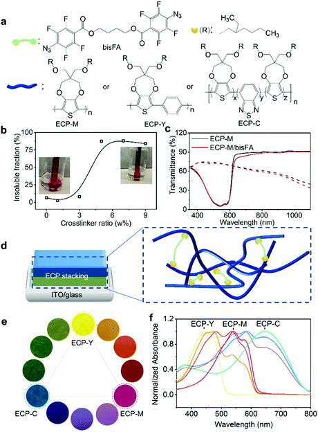
An electrochromic polymer (ECP) changes its color due to electrochemical redox reactions, which is known as electrochromism. Polymer electrochromics can be fast, cyclically stable, and energy-efficient, giving them enormous potential in applications such as displays,1–4 optical shutters (smart window, sunglass),5–7 and electronic papers.8 To pursue future printable electrochromic displays, a wide color range, controllable color switching, and precise on-demand patterns, among others, are essential elements to be explored. At present, a full-color palette of ECPs has been achieved via tuning molecular structures in the synthesis or mixing ECPs with primary colors based on color-mixing theory.9–11 In the synthetic approach, varying the backbones or sidechains of electrochromic polymers to achieve fine color control is complicated and time-consuming, due to the sophisticated polymer structures and color relationships.10 By contrast, color mixing is a well-established strategy to obtain the desired colors and it has been implemented via ECP blending or stacking.12,13 In polymer blending, polymer solutions are blended first and deposited on substrates. For example, Reynolds et al. have reported fine color tuning through blending cyan, magenta, and yellow ECPs.14 In spite of its simplicity and accessibility, the blending approach has limitations in terms of the color control. Due to the disparity in electrochemical onset potentials between the blended ECPs, polymers with a lower onset potential will be oxidized first under a constant potential, inducing unwanted intermediate colors. Alternatively, the stacking of ECPs is a promising way to facilitate the color mixing, where polymers with primary colors are sequentially deposited to generate secondary or more sophisticated color shades. Furthermore, the order of polymers being electrochemically doped can be adjusted through the polymer deposition sequence, which can minimize the intermediate colors. In addition, layered textures and patterns can be constructed based on polymer stacking. Since humans have both tactile and visual texture perception, the stacked patterns will be able to convey more information.15,16 To our knowledge, the stacking strategy has mostly been demonstrated through the in situ electropolymerization of multilayer ECPs on electrodes, which is often incompatible with site-specific large-scale patterning.17 In this work, we present a stacking scheme for solution-processable ECPs with the integration of photolithography and printing to realize full colors and layered textures, laying a foundation for future electrochromic displays. Furthermore, we demonstrate that the electrochemical onset potentials of stacked ECPs can be synchronized to reduce intermediate colors via modulating the stacking sequence. Finally, we use finite element analysis (FEA) to guide the design and stacking of ECPs to achieve the desired colors. A modeling framework allows the numerical prediction of the spectroscopic characteristics and the color appearance of ECPs.To implement the stacking, each polymer layer needs to be solvent-resistant and avoid dissolution during the subsequent coating steps. In our study, a well-studied bis(fluorophenyl azide) (bisFA) crosslinker, whose structure is shown in Fig. 1a, is chosen for co-processing with the ECPs to introduce the solvent resistance.18 The structure of the crosslinker was confirmed using NMR in Fig. S1 (ESI‡). Following the CMY subtractive color-mixing model, three primary ECPs from the poly(3,4-propylenedioxythiophene) (PProDOT) family were employed for stacking, and they are magenta, yellow and cyan, respectively, in their neutral states.19–23 These polymers are denoted as ECP-M, ECP-Y, and ECP-C, as shown in Fig. 1a. Their structures were confirmed using NMR in Fig. S2 (ESI‡). Their molecular weight and dispersity details were characterized using gel permeation chromatography (GPC) as shown in Fig. S3 (ESI‡) and are summarized in Table S1 (ESI‡). To examine the photo-cross-linking behavior of the electrochromic polymer (ECP)/crosslinker, we first used poly(3,4-propylenedioxythiophene) (ECP-M) as the study model. The crosslinker (bisFA) was co-processed with ECP-M with a bisFA/ECP-M weight ratio from 0% to 9%, and they were exposed to ultraviolet (UV) light in a nitrogen-filled glovebox for 5 minutes to complete the cross-linking. During the UV exposure, the predominant cross-linking reaction is nitrene insertion into the alkyl chain of the polymers.24,25 This photo-cross-linking process was confirmed using Fourier-transform infrared spectroscopy in Fig. S4 (ESI‡), where a loss of the N3 peak (νas = 2125 cm−1; νa = 1255 cm−1) and the formation of characteristic C–N (νas ≈ 1216 cm−1) and N–H (ν ≈ 3360 cm−1) bonds were observed after the UV exposure. The differential scanning calorimetry (DSC) data in Fig. S5 (ESI‡) show that crosslinked ECP-M exhibits higher crystallization temperature (Tc) compared with pure ECP-M. This may be due to a more fixed molecular structure caused by the side-chain connections. To quantify the cross-linking efficiency, the cross-linked films were immersed in chloroform for 5 minutes followed by a further chloroform washing. The insoluble fractions of the films are defined as the quotient between their absorbance after solvent washing and their initial absorbance at 540 nm (the maximum absorption of ECP-M). As plotted in Fig. 1b, with the addition of 5–9 wt% of crosslinker, the electrochromic film exhibits an insoluble fraction of more than 85%. The absorbance spectra of the ECPs with different amounts of crosslinker are also examined to study the possible influence of cross-linking on the molecular packing of the ECP-M. As shown in Fig. S6 (ESI‡), a higher crosslinker-to-ECP weight ratio leads to a lower 0–0 to 0–1 vibronic peak ratio of the ECP-M, indicating weaker ECP intrachain ordering. Considering the cross-linking efficiency, 5 wt% of crosslinker is selected to further study the impact of the cross-linking on the electrochemical and electrochromic performance of ECP-M. This investigation is performed using a three-electrode cell with Ag/AgCl as the reference electrode, Pt wire as the counter electrode, and 0.2 M LiTFSI (lithium bis(trifluoromethanesulfonyl)imide)/PC (propyl carbonate) as supportive electrolyte. As shown in Fig. 1c, compared with pure ECP-M, the cross-linked polymer exhibits an almost identical transmittance in both the colored (reduced) and bleached (oxidized) states, suggesting a minimum impact of the cross-linking on its electrochromic performance. The switching kinetics and cyclic voltammograms of pure and cross-linked ECP-M are also compared in Fig. S7 (ESI‡), which demonstrates a negligible difference. Under the same cross-linking conditions, the other two primary ECPs (ECP-C and ECP-Y) also exhibited high insoluble fractions (both are 98%) and had unaffected electrochromic performances, as illustrated in Fig. S8 and S9 (ESI‡). With a cross-linked ECP, another layer of ECP can be spin-coated on top of it, forming a double-layer electrochromic thin film, as demonstrated in the scanning electronic microscopic image in Fig. S10 (ESI‡). As a result, by stacking two of the three primary electrochromic polymers in a variety of thicknesses, a color palette with hues covering the whole visible spectrum can be obtained. Schematic illustrations of the electrochromic stacking and cross-linking are illustrated in Fig. 1d. The pictures and UV-Vis spectra of the color palette are shown in Fig. 1e and f, respectively. The raw transmittance spectra and thickness information for each color in the palette are summarized in Fig. S11 and Table S2 (ESI‡).
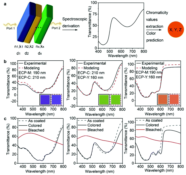
After demonstrating the feasibility of multilayer ECP deposition, we conducted finite elemental analysis (FEA) to simulate the electromagnetic field–ECP stacking interactions using COMSOL, whereby the spectroscopic characteristics and the color appearance of the ECP stackings can be theoretically predicted. The workflow of the optical modeling is shown in Fig. 2a. A multilayer geometry with a high width-to-thickness ratio is built to simulate the stacked polymer thin films. Depolarized electromagnetic waves (port 1 and port 2) with wavelengths from 400 to 800 nm are applied perpendicularly to the geometry from top to the bottom. The intrinsic values of each polymer – the refractive index (n), extinction coefficient (k), and thickness (d) – are applied, respectively, to each layer of the model to study the interaction between the electromagnetic waves and the polymer-stacking system. The transmittance or reflectance spectra can be derived as the simulated results. The chromaticity values are extracted from the spectra to predict the color appearance of the system. The detailed simulation process is included in the ESI‡ notes.
We first applied the optical modeling to double-layer ECPs. To this end, two-layer geometries were constructed and two out of the three primary ECPs (ECP-C, ECP-M, ECP-Y) were assigned to the geometry, generating three stacking scenarios, as shown in Fig. 2b. The refractive indices and absorption coefficients of the three polymers were measured using the Filmetrics technique and are shown in Fig. S12 (ESI‡). In all three stacking scenarios, the thickness of ECP-C, ECP-M and ECP-Y was set to 210 nm, 190 nm, and 160 nm, respectively. For the computational results, the transmittance of the three double-layer ECPs was calculated and is shown as the red dashed curves. Next, we performed experiments to replicate the theoretical results and validate the modeling. To re-create the thickness in the modeling for the actual coating practice, we constructed the thickness–concentration correlation for each polymer, as shown in Fig. S13 (ESI‡). Specifically, solutions with varying concentrations of the three polymers were prepared and spin-coated on glass/ITO substrates at the speed of 1500 rpm. The thicknesses of these films were measured using a profilometer or AFM and fitted as a function of the related concentration for each polymer. Guided by the thickness–concentration correlations, stacking of the ECPs to the target thickness was carried out. The measured transmittance spectra of the ECP stacking samples are shown by the black curves in Fig. 2b. Remarkably, they are in excellent agreement with the modeling values (red dashed curves), demonstrating the effectiveness of the modeling. Furthermore, the xyz chromaticity values were extracted from the experimental and simulated spectra (as shown in Table S3, ESI‡) and were used to forecast the color appearance of each film. As shown in the solid and dashed box insets, the colors from the experimental and modeling spectra are well matched.
Fig. 2c shows the spectroelectrochemical performance of the three stacking electrochromic films. After oxidation and reduction cycles (electrochemical conditioning), the transmittance spectra showed some variation from the as-coated one, which is attributed to morphological changes caused by ion penetration and extraction during the electrochemical cycling. This suggests that the optical modeling value may have some disparity when predicting the color appearance of the film after cycling. However, the small deviation can be resolved using the optical constant values of films after electrochemical conditioning for the optical modeling. The significant change in transmittance between the reduced (colored) and oxidized (bleached) states indicates that the stacking ECPs present a promising electrochromic performance. The double potential step chronoabsorptometry and long-cycling test results of the stacking ECPs are shown in Fig. S14 (ESI‡), and their coloration efficiency, optical contrast, and cycling performance data are summarized in Table S4 (ESI‡). The maximum achievable optical contrast of the ECP stackings is limited by the low-contrast components of the stacked polymers. For instance, when ECP-M is layered with ECP-Y, the optical contrast of the stacking is comparable to ECP-Y, which has a low optical contrast. For reference, the spectroelectrochemistry results of single-layer ECP-C, ECP-M, and ECP-Y are shown in Fig. S15 (ESI‡).
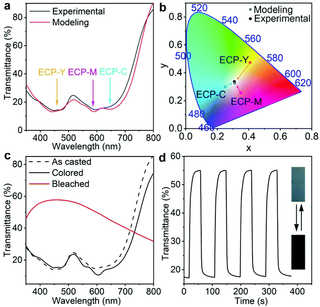
Next, we utilize optical modeling to guide the preparation of a neutral grey ECP by stacking ECP-C, ECP-M, and ECP-Y with appropriate thickness ratios. Neutral grey electrochromic materials have aroused great interest due to their wide applications.26,27 According to the CMY color model, when cyan, magenta, and yellow electrochromic polymers (ECPs) are mixed with equal color contributions, their mixture will display a neutral grey color. However, since ECP-C, ECP-M, ECP-Y have distinct absorption coefficients, their mixing ratio must be carefully tuned to obtain neutral grey, which necessitates dedicated experimental labor. Through optical modeling, we predicted that using the film thicknesses for ECP-C, ECP-M, ECP-Y of 250 nm, 80 nm, and 100 nm, respectively, the maximum absorbance intensities of the three polymers were almost identical, as shown in Fig. 3a. In such a case, the stacking appears a neutral grey. This is also supported by the fact that the xy chromaticity values extracted from modeling spectra are close to the coordinates of the white point in color space, as shown in Fig. 3b. Guided by the modeling and the concentration–thickness correlations, triple-layer ECP stacking was carried out by depositing the three polymers in the sequence ECP-C/ECP-Y/ECP-M on the glass/ITO substrate from their chloroform solutions with concentrations of 26 mg mL−1, 11 mg mL−1, and 12 mg mL−1, respectively. As shown in Fig. 3a and b, the experimentally obtained electrochromic film from stacking of the polymers exhibits almost identical transmittance and xy values to those of the modeling results. Furthermore, the spectroelectrochemistry, double potential step chronoabsorptometry results, and pictures of the stacking polymer are shown in Fig. 3c and d. After electrochemical conditioning, a slight transmittance shift is observed, which is attributed to the morphological change caused by ion penetration and extraction during the electrochemical cycling. The triple-layer electrochromic film shows an optical contrast of 38% at 555 nm between the colored and bleached states, with a switching time of 9 s, which is competitive amongst the reported neutral grey polymers.26–32
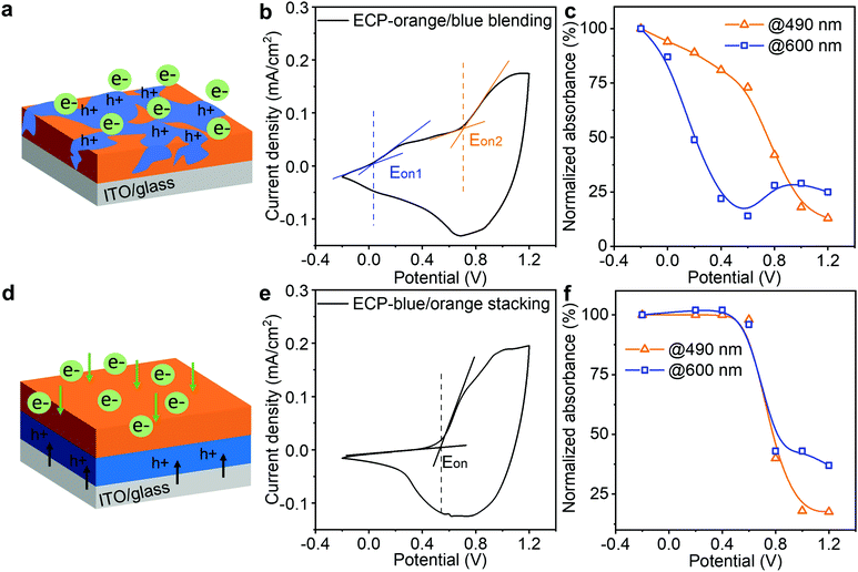
After establishing the ECP stacking and modeling, we studied the impact of the stacking sequence on minimizing the intermediate colors. Having intermediate colors is a common issue in the reported co-processed electrochromic polymers (ECPs), due to the disparity in electrochemical onset potentials of the constituent ECPs.33,34 In our design, via controlling the stacking sequence of the ECPs, their electrochemical onset potentials are synchronized to minimize the intermediate colors. Here, we employ two well-studied ECPs (i.e., ECP-orange and ECP-blue) to demonstrate this approach, since they have very distinct electrochemical onset potentials (0 V and 0.7 V vs. Ag/AgCl for ECP-blue and -orange, respectively).35,36 The molecular structures of the polymers are shown in Fig. S16 (ESI‡). As a reference, we first studied the electrochromic performance of their blends. As illustrated in Fig. 4a, when the two polymers were blended and deposited on the electrode, ECP-blue with the lower electrochemical onset potential will be oxidized first in response to an applied positive electric field, attracting anions from the electrolyte to enter the polymer film. As a result, the cyclic voltammetry of the film presents two separate electrochemical onset potentials at around 0 V and 0.7 V (Fig. 4b), indicating a split electrochemical doping. To monitor the color change, we recorded their absorbance responses during the doping (Fig. S17, ESI‡) and plotted their absorbance decrease at the wavelengths of 490 nm and 600 nm – which are around the maximum absorbance of ECP-blue and ECP-orange, respectively – as a function of the applied voltage, as shown in Fig. 4c. At 0 V, the absorbance at 600 nm starts to decrease, while the absorbance at 490 nm does not exhibit a significant decrease until 0.6 V. This suggests that ECP-blue bleaches earlier than ECP-orange. By contrast, when the two polymers are stacked with ECP-orange on top, electrons will be extracted from ECP-blue to ITO while ions have to diffuse from the ECP-orange/electrolyte interface to the whole ECP stack under a positive potential. Only when the ECP-orange is doped will the ion diffusion become unimpeded to complete the doping of the stacking, as illustrated in Fig. 4d. In Fig. 4e, this mechanism is confirmed by the cyclic voltammogram of the ECP stack, where a single electrochemical onset potential at around 0.58 V is observed, indicating a synchronized electrochemical reaction. In Fig. 4f, the absorbance decreases at 600 nm and 490 nm are also synchronized, suggesting a binary colored-to-bleached switch.
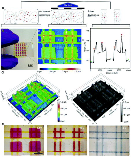
Finally, taking advantage of the UV-triggered cross-linking and the solution-processable ECP stacking strategy, we used photolithography to create delicate patterns with layered textures. The printing process is illustrated in Fig. 5a. Specifically, the multilayer ECP patterns were constructed using a series of repeated processes including photomask covering, 5 minutes of UV illumination and solvent development. The areas that are exposed to UV illumination are crosslinked while the remaining uncross-linked film is washed away using chloroform. The whole printing process is efficient, without the use of any photoresists. As a demonstration, Fig. 5b shows a multilayer ECP pattern that consists of magenta rectangles at the bottom and two pairs of perpendicular yellow lines in the middle and at the top layers. After obtaining the multilayer pattern, we used an optical profilometer to map out a representative periodic structure of this pattern, as shown in Fig. 5c, where the color codes indicate the height of the ECP surface. Remarkably, three height differences were observed on the substrate surface: green rectangular patterns (single layer), orange lines on the rectangular patterns (double layer), and red intersections of the line patterns (triple layer). We further extracted the height profile along the dashed line, from which the height changes at the junction of the two features can be accurately obtained. Here, both the rectangular and line patterns have a thickness of around 200 nm. To visualize this height change in spatial dimensionality, the color-rendered and greyscale-rendered 3D surface topographies of the multilayer patterns are also displayed in Fig. 5d, where various overhangs and undercut structures can be clearly observed. This reflects that rich texture information can be created based on the stacking strategy. Furthermore, the electrochromism of the multilayer pattern was monitored using an optical microscope, as shown in Fig. 5e. At −0.2 V, both ECP-M and ECP-Y are in their neutral states, showing the rectangles and lines in vivid colors. At 1.2 V, both the lines and rectangular patterns are oxidized and thus bleached, while at 0.7 V, only ECP-M that is not covered by the ECP-Y lines is oxidized, since the insulating ECP-Y hinders the ion transmission and the oxidation of the bottom ECP-M. Thus, the lines on top of the ECP-M squares appear to be red. This observation matches the early discussion in Fig. 4. The voltage-dependent ECP patterns enable a more informative color display.
Conclusion
In summary, we demonstrated a facile method to stack solution-processable electrochromic polymers (ECPs), which was achieved by co-processing ECPs with a crosslinker (bisFA). Triggered by UV light, the crosslinker endowed the ECPs with solvent-resistant properties without compromising their electrochromic performance and allowed them to be sequentially deposited. Following CMY subtractive color-mixing theory, three primary ECPs (ECP-C, ECP-M, and ECP-Y) were chosen to be stacked with a variety of thicknesses, generating a full-color palette. COMSOL optical modeling was applied to guide the preparation of double-layer and triple-layer ECPs, producing targeted secondary and tertiary colors. We further integrated the stacking strategy with photolithography, constructing a multilayer ultraprecise ECP pattern with overhang and undercut textures that displayed voltage-dependent electrochromic features. By placing the ECP with the higher electrochemical potential on top, the ECP stacking presented synchronized electrochemical potentials and almost binary colored-to-bleached switching with minimum intermediate colors. We believe that this ECP stacking method will open a new avenue for delicate ECP printing and displays. Despite the benefits of ECP stacking, several aspects need to be further studied to carry this strategy forward. First, when the stacking is fully bleached, the components with lower potential windows may suffer overoxidation. Second, for a desired color, the thickness ratio of the stacked ECP films is fixed, which lessens the opportunity to adjust the film thickness of each layer for an optimal optical contrast.Author contributions
K. C. and J. M. conceived the idea and designed the experiments. K. C. performed the experiments, characterization, and optical modeling. Y. W. prepared the crosslinker. L. Y. and W. W. prepared the electrochromic polymers. X. W. and K. Z. conducted the optical profilometer measurements. D. Z. and H. W. measured the thicknesses of ECP thin films and helped with optical modeling. J. E. performed the Filmetrics measurements. M. A. conducted DSC measurements. K. C. and J. M. drafted the manuscript, and all authors contributed to manuscript preparation.Conflicts of interest
J. M. is a co-founder of Ambilight Inc. A patent disclosure has been filed.Acknowledgements
We are grateful for the financial support from Ambilight Inc. under contract #40001872. We thank Professor Yung C. Shin for providing the access to optical profilometer. D. Z. and H. W. acknowledge the support from the U.S. Office of Naval Research (N00014-20-1-2043).Notes and references
- T. Xu, E. C. Walter, A. Agrawal, C. Bohn, J. Velmurugan, W. Zhu, H. J. Lezec and A. A. Talin, Nat. Commun., 2016, 7, 10479 CrossRef CAS PubMed.
- S. I. Cho, W. J. Kwon, S.-J. Choi, P. Kim, S.-A. Park, J. Kim, S. J. Son, R. Xiao, S.-H. Kim and S. B. Lee, Adv. Mater., 2005, 17, 171–175 CrossRef CAS.
- P. Andersson, R. Forchheimer, P. Tehrani and M. Berggren, Adv. Funct. Mater., 2007, 17, 3074–3082 CrossRef CAS.
- S. Chen, S. Rossi, R. Shanker, G. Cincotti, S. Gamage, P. Kühne, V. Stanishev, I. Engquist, M. Berggren, J. Edberg, V. Darakchieva and M. P. Jonsson, Adv. Mater., 2021, 33, 2102451 CrossRef CAS.
- Y. Kim, M. Han, J. Kim and E. Kim, Energy Environ. Sci., 2018, 11, 2124–2133 RSC.
- J. Kim, M. Rémond, D. Kim, H. Jang and E. Kim, Adv. Mater. Technol., 2020, 5, 1900890 CrossRef CAS.
- C. Ma, M. Taya and C. Xu, Polym. Eng. Sci., 2008, 48, 2224–2228 CrossRef CAS.
- Y. Kondo, H. Tanabe, H. Kudo, K. Nakano and T. Otake, Materials, 2011, 4, 2171–2182 CrossRef CAS.
- P. M. Beaujuge and J. R. Reynolds, Chem. Rev., 2010, 110, 268–320 CrossRef CAS.
- C. M. Amb, A. L. Dyer and J. R. Reynolds, Chem. Mater., 2011, 23, 397–415 CrossRef CAS.
- G. Sonmez, Chem. Commun., 2005, 5251 RSC.
- R. H. Bulloch, J. A. Kerszulis, A. L. Dyer and J. R. Reynolds, ACS Appl. Mater. Interfaces, 2014, 6, 6623–6630 CrossRef CAS PubMed.
- A. M. Österholm, D. E. Shen, J. A. Kerszulis, R. H. Bulloch, M. Kuepfert, A. L. Dyer and J. R. Reynolds, ACS Appl. Mater. Interfaces, 2015, 7, 1413–1421 CrossRef.
- R. H. Bulloch, J. A. Kerszulis, A. L. Dyer and J. R. Reynolds, ACS Appl. Mater. Interfaces, 2015, 7, 1406–1412 CrossRef CAS PubMed.
- J. D. Lieber and S. J. Bensmaia, Proc. Natl. Acad. Sci. U. S. A., 2019, 116, 3268–3277 CrossRef CAS.
- M. Holliins, R. Faldowski, S. Rao and F. Young, Percept. Psycho., 1993, 54, 697–705 CrossRef.
- S. Yan, H. Fu, L. Zhang, Y. Dong, W. Li, M. Ouyang and C. Zhang, Chem. Eng. J., 2021, 406, 126819 CrossRef CAS.
- R.-Q. Png, P.-J. Chia, J.-C. Tang, B. Liu, S. Sivaramakrishnan, M. Zhou, S.-H. Khong, H. S. O. Chan, J. H. Burroughes, L.-L. Chua, R. H. Friend and P. K. H. Ho, Nat. Mater., 2010, 9, 152–158 CrossRef CAS PubMed.
- L. A. Estrada, J. J. Deininger, G. D. Kamenov and J. R. Reynolds, ACS Macro Lett., 2013, 2, 869–873 CrossRef CAS.
- J. A. Kerszulis, C. M. Amb, A. L. Dyer and J. R. Reynolds, Macromolecules, 2014, 47, 5462–5469 CrossRef CAS.
- C. M. Amb, J. A. Kerszulis, E. J. Thompson, A. L. Dyer and J. R. Reynolds, Polym. Chem., 2011, 2, 812 RSC.
- B. D. Reeves, C. R. G. Grenier, A. A. Argun, A. Cirpan, T. D. McCarley and J. R. Reynolds, Macromolecules, 2004, 37, 7559–7569 CrossRef CAS.
- P. M. Beaujuge, S. V. Vasilyeva, S. Ellinger, T. D. McCarley and J. R. Reynolds, Macromolecules, 2009, 42, 3694–3706 CrossRef CAS.
- M. Schock and S. Bräse, Molecules, 2020, 25, 1009 CrossRef CAS.
- C.-Y. Chang, B.-C. Tsai, Y.-C. Hsiao, M.-Z. Lin and H.-F. Meng, Nano Energy, 2019, 55, 354–367 CrossRef CAS.
- S. V. Vasilyeva, P. M. Beaujuge, S. Wang, J. E. Babiarz, V. W. Ballarotto and J. R. Reynolds, ACS Appl. Mater. Interfaces, 2011, 3, 1022–1032 CrossRef CAS.
- G. Öktem, A. Balan, D. Baran and L. Toppare, Chem. Commun., 2011, 47, 3933 RSC.
- C. Wang, M. Wang, Y. Zhang, J. Zhao and C. Fu, RSC Adv., 2016, 6, 80002–80010 RSC.
- M. İçli, M. Pamuk, F. Algı, A. M. Önal and A. Cihaner, Org. Electron., 2010, 11, 1255–1260 CrossRef.
- M. Guzel, E. Karataş and M. Ak, Smart Mater. Struct., 2019, 28, 025013 CrossRef CAS.
- Z. Xu, H. Yue, B. Wang, J. Zhao, M. Wang, Y. Zhang and Y. Xie, Mater. Des., 2020, 194, 108903 CrossRef CAS.
- K.-R. Lee and G. A. Sotzing, Chem. Commun., 2013, 49, 5192 RSC.
- L. R. Savagian, A. M. Österholm, D. E. Shen, D. T. Christiansen, M. Kuepfert and J. R. Reynolds, Adv. Opt. Mater., 2018, 6, 1800594 CrossRef.
- T. Jarosz, K. Gebka, A. Stolarczyk and W. Domagala, Polymers, 2019, 11, 273 CrossRef.
- K. Cao, D. E. Shen, A. M. Österholm, J. A. Kerszulis and J. R. Reynolds, Macromolecules, 2016, 49, 8498–8507 CrossRef CAS.
- J. F. Ponder, A. M. Österholm and J. R. Reynolds, Macromolecules, 2016, 49, 2106–2111 CrossRef CAS.
Footnotes |
| † Dedicated to Dr. Seth Marder on the occasion of his 60th birthday. |
| ‡ Electronic supplementary information (ESI) available. See DOI: 10.1039/d1mh01098k |
| This journal is © The Royal Society of Chemistry 2022 |

