 Open Access Article
High thermal conductivity thermoplastic polyurethane/boron nitride/liquid metal composites: the role of the liquid bridge at the filler/filler interface†
Zemin
Ji
,
Wenyi
Liu
,
Chenguang
Ouyang
 and
Yanbao
Li
 *
*
College of Material Science and Engineering, Nanjing Tech University, Nanjing 211816, P. R. China. E-mail: ybli@njtech.edu.cn; lyanbao@163.com
First published on 28th July 2021
Abstract
Polymer composites with high thermal conductivity (TC) as electronic packaging materials play a critical role in dissipating heat in microelectronic devices. Among the several methods to improve their TC, connection of heat fillers in the heat pathway using the bridging technique is an effective strategy. In this article, we prepared thermoplastic polyurethane composites (TPU/BN/LM) with solid/liquid hybrid fillers of boron nitride (BN) and liquid metal (LM) via hand grinding and solution casting. The TPU/BN/LM composite with 40 vol% of a hybrid filler has a TC of 2.64 ± 0.10 W m−1 K−1, 2.02 times that of the TPU/BN composite (1.31 ± 0.07 W m−1 K−1). Moreover, this TPU/BN/LM composite has a tensile strength of 7.35 ± 0.85 MPa and elongation at break of 204 ± 7%, which is 2.07 times and 1.61 times those of the TPU/BN composite containing the same filler content, respectively. The enhancement of thermal conductivity and mechanical properties is originated from the connection of BN platelets by the liquid bridge of LM because LM wets BN platelets and LM fills up the gap of BN platelets. The thermally conductive bridge reduces the interfacial thermal resistance at filler/filler interface through strong interaction and surface-to-face (2D) contact. This liquid bridging technique is expected to provide an alternative strategy for preparing high thermal conductivity composites through enhancement of the filler/filler interface.
1. Introduction
To reduce the interfacial thermal resistance between a heat sink and electronic components, high thermal conductivity materials are applied as thermal interface materials (TIMs).1 With the development of the microelectronic technique, TIMs play an increasingly important role to dissipate heat and extend the lifetime of the devices. TIMs include thermal greases, thermal pads, phase change materials, thermal gels, thermal conductive adhesives and solders.2 Thermally conductive polymers are popular for their low density, low cost, and electrical insulation.3–5 However, general polymers usually have a low thermal conductivity (TC, <0.5 W m−1 K−1).6 The TC of polymers has been improved effectively by adding high heat fillers such as ceramics,7–9 metals,10 carbon fillers11,12 and metallic oxides.13,14 The interface is the key issue to control the TC of the polymer composites because phonon scattering usually occurs at the filler/filler or filler/polymer interfaces, which further leads to interfacial thermal resistance (ITR). Strategies for decreasing the ITR at the filler/filler interface include modification,15 orientation,16,17 3D network structure,18 and hybridization19 of the heat fillers.Recently, the bridging technique has been used to modify the filler/filler or filler/polymer interfaces.20–25 “Soft” blocks such as 0D nanoparticles,22,26–29 1D nanotubes/nanowires/whiskers30–36 and 2D nanosheets,23,37–39 are employed to bridge “hard” heat fillers at the filler/filler interfaces. ITR can be effectively reduced due to the thermal bridging of the fillers.25 Moreover, a cationic-branched polyethyleneimine (PEI) has been utilized to build a bridged structure between the filler and the polymer.40 Phonons propagate across the interfaces through a thermal bridge with decreased phonon scattering, and the TC of polymer composites becomes highly enhanced.40 Zhu et al.41,42 reported that organic molecules build a thermal bridge between polymer chains to construct the phonon transport pathway. In general, bridging agents are solid, and work through chemical bonding,25 π–π interactions,38 hydrogen bonding,43 and even van der Waals forces.23
In general, the filler/filler interface is a point-to-point (0D) solid/solid contact, where ITR is high. The ITR is reduced due to a linear (1D) solid/solid contact after bridging of carbon nanotubes.44,45 The ITR will reduce further in the presence of a surface-to-surface (2D) contact. It is impossible to achieve a 2D solid/solid contact due to the hard nature of the solid fillers. However, a 2D solid/liquid contact will be obtained when a liquid phase is used as a bridging agent to connect the solid fillers. However, a liquid bridging agent is rarely reported.
A gallium-based liquid metal (LM) with a high TC (>16.0 W m−1 K−1) has been used as a heat filler to improve the TC of polymers.46–49 A LM in the liquid state at room temperature can flow during the processing. Then, the LM can be employed as soft bridge to connect solid fillers to form a 2D contact of the heat fillers in a polymer matrix, which should have a high TC.
Herein, a LM was used as a liquid bridging agent to connect heat fillers at the filler/filler interface in a polymer matrix. Thermoplastic polyurethane composites (TPU/BN/LM) with solid/liquid hybrid fillers of boron nitride (BN) and LM were prepared by hand grinding and solution casting. The TPU/BN/LM composite has a high TC of 2.64 ± 0.10 W m−1 K−1 due to the connected heat pathway of solid BN fillers bridged by a liquid LM phase.
2. Experimental
2.1 Materials
h-BN platelets (with a purity of 99%, and a diameter of 15 µm) were purchased from Dandong Rijin Science and Technology Co., Ltd (Liaoning, China). The gallium, indium, and tin (all with a purity of 99.99%) were purchased from Beijing Yao Sheng Cai Technology Co., Ltd (Beijing, China). TPU (A85) was obtained from BASF-YPC Co., Ltd (Jiangsu, China). N,N-Dimethylformamide (DMF) was obtained from Sinopharm Chemical Reagent Co. Ltd (Shanghai, China). All reagents were commercially available and were used without further purification.2.2 Preparation of TPU/BN/LM composites
Firstly, gallium, indium and tin (Ga![[thin space (1/6-em)]](https://www.rsc.org/images/entities/char_2009.gif) :
:![[thin space (1/6-em)]](https://www.rsc.org/images/entities/char_2009.gif) In
In![[thin space (1/6-em)]](https://www.rsc.org/images/entities/char_2009.gif) :
:![[thin space (1/6-em)]](https://www.rsc.org/images/entities/char_2009.gif) Sn = 68.5
Sn = 68.5![[thin space (1/6-em)]](https://www.rsc.org/images/entities/char_2009.gif) :
:![[thin space (1/6-em)]](https://www.rsc.org/images/entities/char_2009.gif) 21.5
21.5![[thin space (1/6-em)]](https://www.rsc.org/images/entities/char_2009.gif) :
:![[thin space (1/6-em)]](https://www.rsc.org/images/entities/char_2009.gif) 10, a mass ratio) were added to a three-necked flask in an N2 atmosphere. After stirring for 30 min under 60 °C, the LM was collected and stored in a vacuum desiccator.
10, a mass ratio) were added to a three-necked flask in an N2 atmosphere. After stirring for 30 min under 60 °C, the LM was collected and stored in a vacuum desiccator.
Secondly, BN platelets and LM (BN![[thin space (1/6-em)]](https://www.rsc.org/images/entities/char_2009.gif) :
:![[thin space (1/6-em)]](https://www.rsc.org/images/entities/char_2009.gif) LM = 30
LM = 30![[thin space (1/6-em)]](https://www.rsc.org/images/entities/char_2009.gif) :
:![[thin space (1/6-em)]](https://www.rsc.org/images/entities/char_2009.gif) 10, a volume ratio) were mixed by hand grinding for 30 min (Fig. 1a). BN/LM hybrid fillers were obtained.
10, a volume ratio) were mixed by hand grinding for 30 min (Fig. 1a). BN/LM hybrid fillers were obtained.
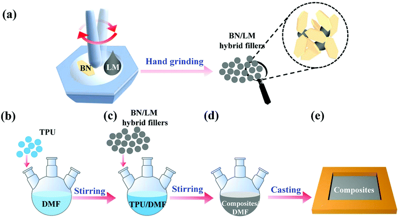 | ||
| Fig. 1 Schematic diagram of the preparation processing of (a) BN/LM hybrid filler by hand grinding and (b–e) TPU/BN/LM composites by solution casting. | ||
Finally, the TPU solution (25 vol%) was prepared by dissolving TPU particles in DMF (Fig. 1b). Then BN/LM hybrid fillers were added into the TPU solution (Fig. 1c). After stirring for 1 h, the TPU/BN/LM suspension was poured into a mould (6 cm × 6 cm × 4 mm, Fig. 1d and e). TPU/BN/LM composites were obtained after being dried in a vacuum oven at 60 °C for 30 h.
2.3 Characterization
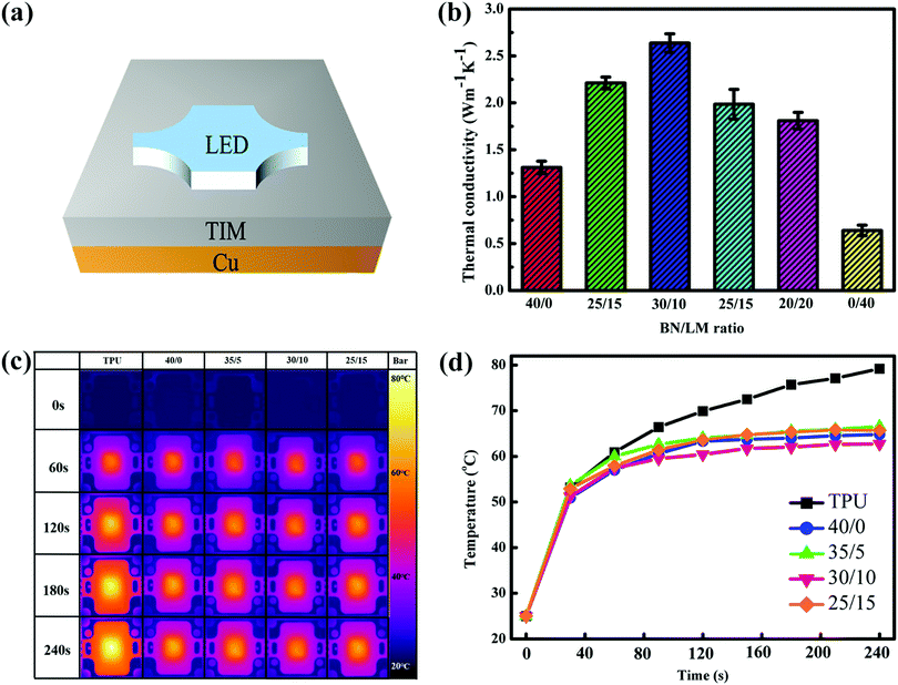
SEM specimens were fractured in liquid nitrogen, then sputter-coated with a thin gold layer. The morphology of the fractured surface of TPU/BN/LM composites was observed on a scanning electron microscope (SEM, JSM-7800F, JEOL, Tokyo, Japan) at an accelerating voltage of 4 kV. X-Ray diffraction (XRD) measurement was conducted on an ARL X’TRA X-ray diffractometer (SmartLab™ 3 kW, Rigaku, Tokyo, Japan) using Cu Kα radiation (λ = 0.154 nm) from 5° to 80° of 2θ at a scanning rate of 10° min−1.The TC of our samples was tested by thermal conductivity tester (TC3000E, Xi’an Xiaxi Electronic Technology Co., Ltd) at 25 °C. The sample was placed as a TIM between a LED chip (10 W) and a Cu heat sink (Fig. 2a) while an infrared thermal camera (FOTRIC 220, USA) was employed to record the surface temperature of the LED chip. The dumbbell-shaped specimens (2 mm wide and 35 mm long) were used to measure the tensile properties of the composites by the electronic universal testing machine (CMT5245, Shenzhen New Sansi Laboratory Equipment Co., Ltd) under a crosshead speed of 50 mm min−1 at room temperature according to ISO 37-2017. Each composite has five specimens.
3. Results and discussion
The raw BN used in our work is in the shape of a platelet with a size of about 15 µm as shown in Fig. S1a (ESI†). BN platelets are bonded together by LM to form BN/LM hybrid microparticles with a size of 50–60 µm as shown in Fig. S1b (ESI†) after hand grinding. Moreover, BN/LM hybrid fillers are solid without fluidity as shown in Fig. S2 (ESI†). These BN/LM microparticles were employed to fill the TPU matrix as hybrid fillers as shown in Fig. 1. Some LM droplets aggregate on the surface of the TPU/LM composites with 40 vol% LM, while there is no LM droplet on the surface of the TPU/BN/LM composites with BN/LM hybrid fillers as shown in Fig. S3 (ESI†). This implies that the LM phase cannot leak from the TPU/BN/LM composites.3.1 Thermal properties
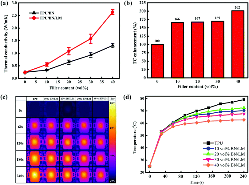
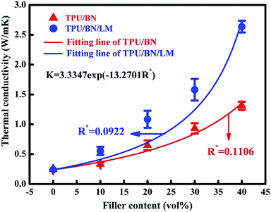
The TC of TPU/BN/LM composites with different BN/LM ratios is shown in Fig. 2b. When the total content of the BN/LM hybrid fillers was fixed at 40 vol%, the TC of the composites with a BN/LM ratio of 40/0, 35/5, 30/10, 25/15, 20/20 and 40/0 is 1.31 ± 0.07, 2.21 ± 0.06, 2.64 ± 0.10, 1.99 ± 0.16, 1.81 ± 0.09 and 0.64 ± 0.06 W m−1 K−1, respectively. The BN/LM ratio affects the TC of TPU/BN/LM composites. The TC of the TPU/BN/LM composite with a BN/LM ratio of 30/10 is the highest. To investigate visually their practical thermal management performance, pure TPU and TPU/BN/LM composites were used as TIMs between a LED chip (10 W) and a Cu heat sink as shown in Fig. 2a. Fig. 2c and d show infrared thermal images and the surface temperature of the LED chip when it works. Its surface temperature increases in all TIMs as soon as the LED chip is powered on. The surface temperature of the LED chip with all TPU/BN/LM TIMs has a lower temperature than the one with the pure TPU TIM. The surface temperature of the LED chip with the pure TPU TIM increases rapidly and reaches an equilibrium at 79 °C. The surface temperature of the LED chip with TPU/BN/LM composites with BN/LM ratios of 40/0, 35/5, 30/10, and 25/15, respectively, increases slowly and reaches an equilibrium at 66.5, 64.8, 62.7 and 65.7 °C, respectively. The surface temperature of the LED chip using the TPU/BN/LM TIM with a BN/LM ratio of 30/10 decreases by 16.3 °C, in comparison to the one using the pure TPU TIM. Obviously, the TPU/BN/LM composite with a BN/LM ratio of 30/10 has the best thermal properties. So, the BN/LM hybrid filler with a BN/LM ratio of 30/10 was used in the following investigation.The effect of filler content on the thermal properties of TPU/BN/LM composites is shown in Fig. 3. The TC of TPU/BN/LM ternary composites and their TPU/BN binary counterparts increases with increasing filler content (Fig. 3a). Interestingly, the TC of TPU/BN/LM ternary composites is higher than that of their TPU/BN binary counterparts with the same filler content. TC enhancement (φ) is defined to compare the TC of TPU/BN/LM ternary composites and their TPU/BN binary counterparts according to eqn (1),
 | (1) |
The surface temperature of the LED chip on TPU/BN/LM composites with a BN/LM content of 10, 20, 30 and 40 vol% reaches an equilibrium at 72.6, 70.3, 67.7 and 62.7 °C, respectively (Fig. 3c and d). It means that the TPU/BN/LM composite containing 40 vol% hybrid filler content has the best thermal management capability.
The effect of the BN size on the thermal properties of TPU/BN/LM composites with 40 vol% BN/LM at a BN/LM ratio of 30/10 is shown in Fig. S4 (ESI†). The TC of TPU/BN/LM composites with a BN size of 100 nm, 5 µm and 15 µm, respectively, is 0.73 ± 0.07, 1.42 ± 0.06, 2.64 ± 0.10 W m−1 K−1, respectively.
3.2 Microstructure
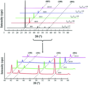
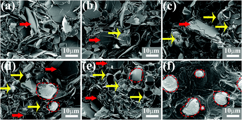
To characterise the microstructure of TPU/BN/LM composites and BN/LM hybrid fillers, XRD and SEM were conducted. In the XRD patterns (Fig. 4), TPU/BN/LM composites have sharp diffraction peaks at 2θ = 26.5°, 41.7° and 54.7°, which correspond to BN lattice planes of (002), (100) and (004), respectively. While the BN/LM ratio decreases, the intensity of these sharp peaks decreases due to reduction of the BN content in BN/LM hybrid fillers. The intensity ratio (I002/I100) of the (002) and (100) planes is used to characterise the orientation degree of anisotropic BN platelets.50 As shown in Fig. 4, all composites with different BN/LM ratios have similar I002/I100 value (∼19), which is similar to that of the pure BN platelets (17). It means that the orientation of BN is not found in TPU/BN/LM composites. In another word, BN platelets are dispersed randomly in the polymer matrix, which will be confirmed further by the following SEM results.SEM images of the fractured surface of TPU/BN/LM composites containing 40 vol% BN/LM hybrid filler with different ratios are shown in Fig. 5. In all samples, BN platelets are dispersed randomly in the TPU matrix. Many gaps exist between BN platelets in the TPU/BN composite without the LM phase (Fig. 5a). The LM phase (in grey colour marked by yellow arrows) fills the gap between BN platelets (in black colour marked by red arrows) in TPU/BN/LM composites (Fig. 5b–e). These filling phenomena become more obvious when the LM content increases in TPU/BN/LM composites with a BN/LM ratio of 30/10 and 20/20 as shown in Fig. 5d and e. BN platelets in the polymer matrix have been bonded together by LM in Fig. 5e similarly to the ones in Fig. S1b (ESI†). It is worth pointing out that LM microdroplets (circled by dashed line) appear in the composites containing a higher LM content (Fig. 5d and e) and the TPU/LM composite (Fig. 5f).
Fig. 6 shows SEM images of TPU/BN/LM composites with different BN/LM contents. BN/LM hybrid fillers are dispersed separately in the TPU matrix with a low filler content (Fig. 6a and b). But BN/LM hybrid fillers can be seen clearly and their network forms in the TPU matrix with a high filler content (Fig. 6c and d). Heat transfers through its pathway based on this network. This pathway contributes to the increasing TC. It is worth stating that BN platelets in TPU/BN/LM composites are in a disordered state, which is consistent with XRD results (Fig. 4).
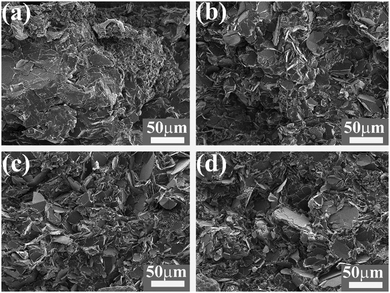 | ||
| Fig. 6 SEM images (the fractured surface) of TPU/BN/LM composites with different filler contents: (a) 10 vol%, (b) 20 vol%, (c) 30 vol% and (d) 40 vol%. | ||
3.3 Mechanical properties
Mechanical properties of TPU/BN/LM and TPU/BN composites are shown in Fig. 7. The BN/LM ratio affects the mechanical properties of the TPU/BN/LM composites. The tensile strength of the TPU/BN/LM composites increases first, and then decreases with the increasing LM phase (Fig. 7a). The highest tensile strength (7.35 ± 0.85 MPa) is obtained when the BN/LM ratio is 30/10. Meanwhile, the elongation at break of TPU/BN/LM composites increases monotonously from 127 ± 7% to 224 ± 22% with the increasing of LM phase. Hence, the TPU/BN/LM composite with a BN/LM ratio of 30/10 has optimized mechanical properties.The filler content affects the mechanical properties of TPU-based composites as shown in Fig. 7b and c. The tensile strength and elongation at break of TPU/BN/LM and TPU/BN composites decrease monotonously, respectively, when the filler content increases. Interestingly, the tensile strength and elongation at break of TPU/BN/LM composites are higher than those of TPU/BN composites, which is attributed to the easy deformation of LM and low BN content in TPU/BN/LM composites. On the one hand, the absolute BN content in the TPU/BN/LM composites is lower than the one in the TPU/BN composites because the BN/LM ratio of the BN/LM hybrid filler is fixed at 30/10, which is beneficial to obtain the mechanical properties. On the other hand, the liquid LM phase in TPU/BN/LM composites deforms easily under stress, which is attributed the higher elongation at break of TPU/BN/LM composites.
3.4 Liquid bridge
The TC of TPU-based composites has improved obviously after BN/LM hybrid fillers or BN single fillers were added (Fig. 2 and 3). Moreover, TPU/BN/LM ternary composites have a higher TC than their TPU/BN binary counterparts with the same filler content (Fig. 3a). This implies that the BN/LM hybrid filler has a better enhancement effect than the BN single filler.51 This enhancement may be attributed to the interfacial state of BN/LM hybrid fillers in TPU/BN/LM ternary composites.The modified Hashin–Shtrikman model (eqn (2)–(4)) was employed to fit our experimental results as reported.52,53
 | (2) |
 | (3) |
K = 13.3347![[thin space (1/6-em)]](https://www.rsc.org/images/entities/char_2009.gif) exp(−13.2701R*) exp(−13.2701R*) | (4) |
In order to explain the BN/LM interfacial state, another BN/LM filler was prepared by sonication mixing (described in ESI†) and added into TPU matrix to form TPU/BN/LM composite by solution casting. Unfortunately, the LM microdroplet exists separately in BN platelets as shown in Fig. S1c (ESI†), which implies that the BN/LM filler prepared by sonication mixing has poor interfacial interaction. Surprisingly, TC of the TPU/BN/LM composite filled by the sonication-mixed BN/LM filler is 1.43 ± 0.08 W m−1 K−1, which is much lower than that (2.64 ± 0.10 W m−1 K−1) of the TPU/BN/LM composite filled by the hand-ground BN/LM filler (Fig. S5, ESI†). Similarly, the tensile strength and elongation at break of the TPU/BN/LM composite filled by the sonication-mixed BN/LM filler are much smaller than those of the TPU/BN/LM composite filled by the hand-ground BN/LM filler, and even smaller than those of the TPU/BN binary composite (Fig. S6, ESI†).
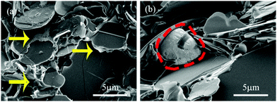
Moreover, LM exists separately as microdroplets between BN platelets in the TPU/BN/LM composite filled by the sonication-mixed BN/LM filler (Fig. S7a, ESI†). However, LM exists in an irregular shape between BN platelets in the TPU/BN/LM composite filled by the hand-grinded BN/LM filler, which means that these platelets have been connected together by bridging of LM binder (Fig. 5, 6 and 9b). The filler/filler interfaces in these two composites are different.
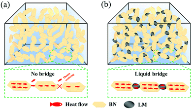
The contact angle was measured to characterise the wettability of LM to BN as shown in Fig. S7 (ESI†). Firstly, LM does not wet the BN surface (Fig. S7a, ESI†). LM droplets were rubbed on the BN film in order to improve their wettability. Fortunately, the contact angle of the rubbed LM decreases obviously (Fig. S7b, ESI†). It indicates that the wettability of LM to BN improves significantly after rubbing. A sold thin oxide coating (gallium oxide) form immediately on the surface of LM droplets in the presence of oxygen.55 The oxide coating not only destroys the wettability of LM, but also changes the BN/LM interface from the liquid/solid state to the solid/solid state. The fresh surface without oxide coating after rubbing provides good wettability of LM to BN. LM droplets form during sonication and have a solid oxide surface. These LM droplets with a solid surface cannot wet BN platelets as shown in Fig. S1c (ESI†) and Fig. 9b. Hence, the poor BN/LM and BN/BN interfaces are obtained in the TPU/BN/LM composite filled by the sonication-mixed BN/LM filler, which has low mechanical properties and TC. However, the LM phase with fresh liquid surface is obtained during hand grinding. The fresh LM phase without solid surface wets well BN platelets, fills the gap of BN/BN interfaces and then BN platelets are bound together due to the fresh LM as a binder as shown in Fig. S1b (ESI†). In another word, BN platelets have been connected through a liquid bridge by LM binder. Importantly, connection of BN platelets by LM binder is still observed in TPU/BN/LM composites (Fig. 4, 5 and 9a). In other words, the LM bridge can be observed clearly in Fig. 9a.
The good wetting of LM to BN platelets leads to the two results: (1) the interaction of the filler/filler interface has been enhanced by a liquid bridge, which leads to mechanical enhancement of TPU/BN/LM composites with comparison to their TPU/BN counterparts (Fig. 7), and (2) the contact surface area between solid/liquid fillers increases due to the wetting of LM to BN platelets, which changes the interfacial contact from 0D contact to 2D contact (Fig. 3 and 9b). These two factors can effectively decrease ITR. Then, the heat conduction pathway with low ITR forms in TPU/BN/LM composites through BN/LM hybrid fillers with the help of BN connection bridged by LM. Their TC is enhanced significantly (Fig. 2 and 3). Fig. 10 demonstrates that heat flow transmits in the TPU/BN composites and TPU/BN/LM composites, respectively.
Moreover, TC of the BN/polymer composites reported previously and our sample is listed in Table S1 (ESI†). The processing method seriously affects the TC of polymer composites. BN/polymer composites prepared by the casting method have lower TC than those by hot-pressing method due to orientation of BN platelets in the hot-pressed polymer matrix. However, our casted composite has a higher TC than those with random BN dispersion, which is due to the liquid bridge of LM in our sample. TPU/BN and TPU/BN/LM have higher volume resistivity (1.27 × 10¹⁴ and 3.23 × 10¹³ Ω·m) than TPU (6.41 × 10¹² Ω m) as shown in Fig. S8 (ESI†), despite adding LM. This is due to the high volume resistivity of BN (1014–1016 Ω m).56 Then the LM does not deteriorate the electrical properties of TPU based composites.
4. Conclusions
In this work, the liquid bridging technique has been introduced to strengthen the filler/filler interface via the connection of a liquid phase. The strong heat pathway based on BN connection form by LM bridging through wetting of LM to BN platelets. Then the TC value of TPU/BN/LM composites was highly improved to 2.64 ± 0.10 W m−1 K−1. Moreover, their mechanical properties were also enhanced due to this good interfacial interaction. The liquid bridging technique provides a potential strategy for connecting hard heat fillers and to prepare high thermal conductivity polymer composites with low ITR.Conflicts of interest
There are no conflicts to declare.Acknowledgements
This work was funded by the Postgraduate Research & Practice Innovation Program of Jiangsu Province (KYCX19_0836), the Priority Academic Program Development of Jiangsu Higher Education Institutions (PAPD).References
- R. Prasher, Proc. IEEE, 2006, 94, 1571 CAS
.
- J. Hansson, T. M. J. Nilsson, L. Ye and J. Liu, Int. Mater. Rev., 2018, 63, 22 CrossRef CAS
.
- Y. Han, X. Shi, X. Yang, Y. Guo, J. Zhang, J. Kong and J. Gu, Compos. Sci. Technol., 2020, 187, 107944 CrossRef CAS
.
- D. Bao, Y. Cui, F. Xu, M. Li, K. Li, X. Zhang, Z. Liu, Y. Zhu and H. Wang, Ceram. Int., 2020, 46, 27531 CrossRef CAS
.
- D. An, S. Cheng, Z. Zhang, C. Jiang, H. Fang, J. Li, Y. Liu and C. P. Wong, Carbon, 2019, 155, 258 CrossRef CAS
.
- M. Hu, D. Yu and J. Wei, Polym. Test., 2007, 26, 333 CrossRef CAS
.
- T. F. Qin, H. Wang, J. He, Q. Q. Qu, Y. S. Da and X. Y. Tian, Express Polym. Lett., 2020, 14, 1169 CrossRef CAS
.
- Y. Wang, X. Zhang, X. Ding, P. Zhang, M. Shu, Q. Zhang, Y. Gong, K. Zheng and X. Tian, Composites, Part B, 2020, 199, 108267 CrossRef CAS
.
- C. P. Yu, W. B. Gong, W. Tian, Q. C. Zhang, Y. C. Xu, Z. Y. Lin, M. Hu, X. D. Fan and Y. G. Yao, Compos. Sci. Technol., 2018, 160, 199 CrossRef CAS
.
- N. M. Sofian, M. Rusu, R. Neagu and E. Neagu, J. Thermoplast. Compos. Mater., 2001, 14, 20 CrossRef CAS
.
- X. Jin, J. Wang, L. Dai, X. Liu, L. Li, Y. Yang, Y. Cao, W. Wang, H. Wu and S. Guo, Chem. Eng. J., 2020, 380, 122475 CrossRef CAS
.
- L. Ren, Y. Ren, Y. Zhang, K. Orzechowski, K. Kulacz, M. Pochec and S. Bai, Nanotechnology, 2020, 31, 475710 CrossRef CAS PubMed
.
- J. Li, X. Zhao, Z. Zhang, Y. Xian, Y. Lin, X. Ji, Y. Lu and L. Zhang, Compos. Sci. Technol., 2020, 186, 107930 CrossRef CAS
.
- Y. Ul Haq, I. Murtaza, S. Mazhar, N. Ahmad, A. A. Qarni, Z. Ul Haq, S. A. Khan and M. Iqbal, J. Appl. Polym. Sci., 2020, 137, e49197 CrossRef
.
- B. Ji, Y. Wu, P. Zhang and X. Zhao, J. Polym. Res., 2020, 27, 239 CrossRef CAS
.
- Y. Han, S. Lv, C. Hao, F. Ding and Y. Zhang, Thermochim. Acta, 2012, 529, 68 CrossRef CAS
.
- T. Fei, Y. Li, B. Liu and C. Xia, High Perform. Polym., 2020, 32, 324 CrossRef CAS
.
- B. Liu, Y. Li, T. Fei, S. Han, C. Xia, Z. Shan and J. Jiang, Chem. Eng. J., 2020, 385, 123829 CrossRef CAS
.
- F. Y. Yuan, H. B. Zhang, X. Li, X. Z. Li and Z. Z. Yu, Composites, Part A, 2013, 53, 137 CrossRef CAS
.
- S. D. Yang, X. Sun, J. Q. Shen, Y. Li, L. Xie, S. H. Qin, B. Xue and Q. Zheng, ACS Sustainable Chem. Eng., 2020, 8, 17639 CrossRef CAS
.
- L. Yang, L. Zhang and C. Z. Li, Compos. Sci. Technol., 2020, 200(8), 108429 CrossRef CAS
.
- G. R. Pan, Y. M. Yao, X. L. Zeng, J. J. Sun, J. T. Hu, R. Sun, J. B. Xu and C. P. Wong, ACS Appl. Mater. Interfaces, 2017, 9, 33001 CrossRef CAS PubMed
.
- Y. M. Yao, X. L. Zeng, F. F. Wang, R. Sun, J. B. Xu and C. P. Wong, Chem. Mater., 2016, 28, 1049 CrossRef CAS
.
- Y. M. Yao, X. L. Zeng, G. R. Pan, J. J. Sun, J. T. Hu, Y. Huang, R. Sun, J. B. Xu and C. P. Wong, ACS Appl. Mater. Interfaces, 2016, 8, 31248 CrossRef CAS PubMed
.
- K. P. Ruan, X. T. Shi, Y. Q. Guo and J. W. Gu, Compos. Commun., 2020, 22, 100518 CrossRef
.
- J. Huang, W. L. Yang, J. J. Zhu, L. C. Fu, D. Y. Li and L. P. Zhou, Composites, Part A, 2019, 123, 79 CrossRef CAS
.
- L. L. Ren, X. L. Zeng, X. Zhang, R. Sun, X. Y. Tian, Y. P. Zeng, J. B. Xu and C. P. Wong, Composites, Part A, 2019, 119, 299 CrossRef CAS
.
- J. J. Sun, Y. M. Yao, X. L. Zeng, G. R. Pan, J. T. Hu, Y. Huang, R. Sun, J. B. Xu and C. P. Wong, Adv. Mater. Interfaces, 2017, 4(10), 1700563 CrossRef
.
- S. D. Yang, B. Xue, Y. Li, X. J. Li, L. Xie, S. H. Qin, K. H. Xu and Q. Zheng, Chem. Eng. J., 2020, 383(9), 123072 CrossRef CAS
.
- S. S. Song, B. Y. Hu, G. Qu, Z. M. Wang, G. R. Qi, K. L. Tang and B. A. Li, Ind. Eng. Chem. Res., 2020, 59, 17845 CrossRef CAS
.
- J. Dong, L. Cao, Y. Li, Z. Q. Wu and C. Q. Teng, Compos. Sci. Technol., 2020, 196(11), 108242 CrossRef CAS
.
- X. Liang and F. H. Dai, ACS Appl. Mater. Interfaces, 2020, 12, 3051 CrossRef CAS PubMed
.
- G. S. He, X. Li, Y. Dai, Z. J. Yang, C. C. Zeng, C. M. Lin and S. W. He, Composites, Part B, 2019, 162, 678 CrossRef CAS
.
- B. F. Nan, K. Wu, Y. C. Liu, L. Q. Xiao, W. L. Chen, E. X. Jiao, Z. Y. Tan, G. K. Chen and M. G. Lu, J. Mater. Sci.: Mater. Electron., 2019, 30, 19928 CrossRef CAS
.
- T. Wang, C. Wei, L. Yan, Y. Liao, G. Wang, L. Zhao, M. Fu and J. Ren, Compos. Interfaces, 2020, 1, DOI:10.1080/09276440.2020.1855573
.
- N. Song, H. D. Pan, X. S. Hou, S. Q. Cui, L. Y. Shi and P. Ding, RSC Adv., 2017, 7, 46306 RSC
.
- B. Xue, S. D. Yang, X. Sun, L. Xie, S. H. Qin and Q. Zheng, J. Mater. Chem. A, 2020, 8, 14506 RSC
.
- J. W. Ren, Q. H. Li, L. Yan, L. C. Jia, X. L. Huang, L. H. Zhao, Q. C. Ran and M. L. Fu, Mater. Des., 2020, 191(10), 108663 CrossRef CAS
.
- Z. M. Wang, Y. Y. Cao, D. C. Pan and S. Hu, Polymers, 2020, 12(15), 1121 CrossRef CAS PubMed
.
- H. Y. Li, Y. Gao, P. L. Zhu, X. M. Du, X. C. Yu, L. Q. Ma, G. Li, R. Sun and C. P. Wong, Adv. Mater. Interfaces, 2019, 6(10), 1900787 CrossRef
.
- N. Mehra, Y. F. Li, X. T. Yang, J. Li, M. A. Kashfipour, J. W. Gu and J. H. Zhu, Composites, Part B, 2019, 166, 509 CrossRef CAS
.
- N. T. Mehra, Y. F. Li and J. H. Zhuo, J. Phys. Chem. C, 2018, 122, 10327 CrossRef CAS
.
- N. Mehra, L. W. Mu and J. H. Zhu, Compos. Sci. Technol., 2017, 148, 97 CrossRef CAS
.
- S. Y. Yang, W. N. Lin, Y. L. Huang, H. W. Tien, J. Y. Wang, C. C. M. Ma, S. M. Li and Y. S. Wang, Carbon, 2011, 49, 793 CrossRef CAS
.
- A. P. Yu, P. Ramesh, X. B. Sun, E. Bekyarova, M. E. Itkis and R. C. Haddon, Adv. Mater., 2008, 20, 4740 CrossRef CAS
.
- Y. Plevachuk, V. Sklyarchuk, S. Eckert, G. Gerbeth and R. Novakovic, J. Chem. Eng. Data, 2014, 59, 757 CrossRef CAS
.
- M. D. Bartlett, N. Kazem, M. J. Powell Palm, X. Huang, W. Sun, J. A. Malen and C. Majidi, Proc. Natl. Acad. Sci. U. S. A., 2017, 114, 2143 CrossRef CAS PubMed
.
- S. Chen, Z. S. Deng and J. Liu, Nanotechnology, 2021, 32(11), 092001 CrossRef CAS PubMed
.
- S. Chen, H. Z. Wang, R. Q. Zhao, W. Rao and J. Liu, Matter, 2020, 2, 1446 CrossRef
.
- B. H. Xie, X. Huang and G. J. Zhang, Compos. Sci. Technol., 2013, 85, 98 CrossRef CAS
.
- N. Mehra, L. Mu, T. Ji, X. Yang, J. Kong, J. Gu and J. Zhu, Appl. Mater. Today, 2018, 12, 92 CrossRef
.
- T. B. Ma, Y. S. Zhao, K. P. Ruan, X. R. Liu, J. L. Zhang, Y. Q. Guo, X. T. Yang, J. Kong and J. W. Gu, ACS Appl. Mater. Interfaces, 2020, 12, 1677 CrossRef CAS PubMed
.
- I. L. Ngo, S. V. P. Vattikuti and C. Byon, Int. J. Heat Mass Transfer, 2017, 114, 727 CrossRef CAS
.
- I. Jo, M. T. Pettes, J. Kim, K. Watanabe, T. Taniguchi, Z. Yao and L. Shi, Nano Lett., 2013, 13, 550 CrossRef CAS PubMed
.
- X. Zhao, S. Xu and J. Liu, Front. Energy, 2017, 11, 535 CrossRef
.
- D. Pan, F. M. Su, H. Liu, Y. Ma, R. Das, Q. Hu, C. T. Liu and Z. H. Guo, Chem. Rec., 2020, 20, 1314 CrossRef CAS PubMed
.
Footnote |
| † Electronic supplementary information (ESI) available. See DOI: 10.1039/d1ma00637a |
| This journal is © The Royal Society of Chemistry 2021 |

