
 Open Access Article
 This Open Access Article is licensed under a Creative Commons Attribution-Non Commercial 3.0 Unported Licence
An anticounterfeiting technology combining an InP nanoparticle ink and a versatile optical device for authentication†
Didem
Taşcıoğlu
 ab,
Seçil
Sevim Ünlütürk‡
c and
Serdar
Özçelik
*c
ab,
Seçil
Sevim Ünlütürk‡
c and
Serdar
Özçelik
*c
aDepartment of Material Science and Engineering, Izmir Institute of Technology, Urla, 35430, İzmir, Turkey
bQuantag Nanotechnologies, R&D Lab, Budotek Teknopark, Dudullu OSB Ümraniye, 34776, İstanbul, Turkey
cDepartment of Chemistry, Izmir Institute of Technology, Urla, 35430, İzmir, Turkey. E-mail: serdarozcelik@iyte.edu.tr; Tel: +90 232 750 75 57
First published on 4th August 2021
Abstract
Counterfeiting is a growing issue and causes economic losses. Fluorescent inks containing In(Zn)P/ZnS/DDT colloidal nanoparticles are formulated and combined with a convenient optical device for authentication. The particle size and fluorescent colors of the colloidal nanoparticles were tuned by adjusting the reaction temperature. The particle stability and brightness were improved by the addition of dodecanethiol, coating the particle surface with an organic shell. Security patterns were printed on various substrates by applying the screen-printing technique. The patterns were invisible under daylight but observable under UV-light illumination, displaying five different emission colors. By adjusting the concentration of the nanoparticles in the ink, the security patterns were made almost not observable under UV-light illumination but clearly identified by a commercial fiber optics-based spectrometer and a handheld optical device, called a Quantag sensor that was developed in-house. Furthermore, the spectral signatures of barely noticeable patterns are unambiguously validated by the Quantag sensor. Accordingly, low cost and easily applicable anticounterfeiting technology powered by custom-formulated fluorescent inks and a handheld optical instrument are developed to authenticate valuable documents and products.
1. Introduction
Counterfeiting and adulteration of valuable documents cause economical losses and initiate societal concerns. Anticounterfeiting efforts require advanced materials and technologies to prevent counterfeiting. Fluorescent inks are commonly used as second-level security features; being invisible in the daylight and detectable under UV light. In the last decade, to prevent counterfeiting, security labels have been created using different printing techniques with various fluorescent inks formulated by using rare earth luminescent materials,1–6 perovskite nanocrystals,7,8 carbon dots,9–11 organic dyes,12,13 and quantum dots.14–16 Among various printing methods, screen printing is preferable because it is easily applicable to various substrates.17 Screen printing is a unique technique in terms of quality; it is a process that uses ink or pastes pushed by a template attached or embedded in a web stretched onto a printing frame. Since an intermediate transfer tool is not required, the consistency of the ink is not limited. Long-lasting and durable prints can be produced, providing unrivaled homogeneity and color brilliance. Screen printing can be applied to a variety of substrates from papers to metals to plastics, and even glass and ceramics. These capabilities enable the production of a wide variety of products including smart identity cards, credit cards, technical and industrial parts, automobile components, flat glass and glass containers, etc.18In the past several years, publications applying screen-printing techniques using lanthanide-based luminescent materials have been widely reported for anticounterfeiting.6,19–22 Organic dyes as fluorescent materials are used in this field.12,23 Colloidal quantum dots (cQDs) are considered alternatives to these materials because of their unique optical properties.24,25 Unlike the lightfastness and cost-effectiveness of lanthanide-based materials and broad emission peaks of organic dyes,26 cQDs possess narrow, stable, and tunable photoluminescence emission features.27 In addition, cQDs may be excited by a single wavelength light source because of their broad absorption spectra. With all these distinctive features, cQDs may be regarded as an excellent anticounterfeiting material for contemporary security ink and printing technology.
To prevent counterfeiting, luminescent/fluorescent materials are turned into colorless fluorescent inks that exhibit confidential information when exposed to UV light.28–30 However, as these materials often exhibit monochromatic emissions that are easy to imitate, these security inks offer a low level of protection against counterfeiting. In recent years, luminescent inks made of rare-earth materials have attracted great attention due to their fast response time, high brightness, and efficiency.31–34 However, rare-earth materials-based security inks severely limit scaled-up production due to high cost. Furthermore, it is desired to verify the authenticity of a document illuminated under UV light by visual inspection without using a device.29,32 However, this simplicity would make security patterns predictable and can be easily reproduced. To prevent counterfeiting, utilizing an affordable, widely-used, handy instrument such as a mobile phone or an optical device working with a specially formulated ink may enhance anticounterfeiting procedures.
In this study, we formulated a colloidal nanoparticle (colloidal quantum dot)-based security ink to authenticate valuable documents. Here, we chose indium-based alloyed nanoparticles because the cost of indium-based precursors is much lower than that of the rare-earth element-based materials. On top of that, they can be easily produced at hundreds of grams in one pot,35,36 thereby further lowering the ink cost. Herein, we synthesized In(Zn)P/ZnS/DDT nanoparticles to formulate security inks emitting brightly in various colors. Fluorescence properties of the nanoparticles were adjusted by the reaction temperature, tuning the particle size generating various fluorescent colors. The In(Zn)P/ZnS/DDT colloidal nanoparticles were mixed with a commercial printing varnish to formulate security inks. The inks were used to print security patterns on various substrates including paper, polymer, and glass by applying the screen-printing technique. The security patterns printed were evaluated by using a commercial fiber optics-based spectrometer, and a low-cost, convenient handheld optical device, called a Quantag sensor developed in-house by Quantag Nanotechnologies. The security patterns that were barely detectable under UV light by the naked eye were clearly detectable by the Quantag sensor. The spectral features, wavelengths, and brightness, were validated by a fiber optics-based spectrometer, verifying the readings of the Quantag sensor. It is demonstrated that the security patterns can be printed by using the specially formulated ink and detected at a low cost, using a simple and handy optical device to authenticate the originality of documents or products.
2. Experimental
2.1. Materials and methods
Indium(III) chloride (InCl3, 98%), oleylamine (OA, 70%), trioctylphosphine (TOP, 97%), zinc stearate (technical grade), 1-octadecene (ODE, 90%), 1-dodecanethiol (DDT, ≥98%), sulfur (Merck, 99%) and toluene (ACS reagent, ≥99.7%) were purchased from Sigma-Aldrich. Zinc(II) chloride (ZnCl2, 97%) and tris(diethylamino)phosphine ((DEA)3P, 97%) were purchased from Alfa Aesar. Printcolor series 592 varnish was used to formulate inks.Photoluminescence (PL) and quantum yield (QY)% measurements were performed using a Horiba-Fluorolog with an integrated sphere or USB2000 fiber optics-based spectrometer (Ocean Optics Inc., Dunedin, FL, USA). Absorbance was measured using a Shimadzu UV-3600 UV-vis-NIR spectrophotometer. Particle size measurements were obtained using a DLS (Malvern ZS-Zetasizer). SEM-EDS analysis employed an FEI QUANTA 250 FEG SEM equipped with an Oxford Instruments energy dispersive X-ray analyzer. XRD patterns were obtained using a Bruker D2 phaser-X-ray diffractometer. Fourier transform infrared spectroscopy (FTIR; Thermo Scientific iS10 FT-IR) was used to confirm DDT coating. The thickness of the screen-printed patterns was measured using a KlaTencor MicroXM-100 optical profilometer. An Andor Revolution confocal microscope was used to determine ink homogeneity in the printed patterns. The Quantag sensor is a fiber optics-based device developed in-house (patent protected). It is a handheld and low-cost optical instrument utilizing fiber optical probes to detect and measure fluorescence intensity (brightness) and colors (wavelength) of inks embedded into patterns printed on substrates.
2.2. Synthesis of In(Zn)P core and In(Zn)P/ZnS/DDT core/shell nanoparticles
In(Zn)P/ZnS/DDT colloidal nanoparticles were synthesized by applying a modified hot injection method.37 Briefly, 0.9 mmol of InCl3 and 4.4 mmol of ZnCl2 were mixed in 10.0 mL of oleylamine at 120 °C and stirred for 20 min. After the indium and zinc precursors were completely dissolved under a nitrogen atmosphere, the reaction temperature was increased to a specific predetermined value (varied from 150 to 200 °C). 3.3 mmol tris(diethylamino)phosphine ((DEA)3P) was rapidly injected into the precursor solution to synthesize the core of In(Zn)P nanoparticles. To coat the nanoparticle surface with a ZnS shell, TOP-S and Zn(stearate)2 were prepared individually and added dropwise into the In(Zn)P core nanoparticle dispersion. Firstly, 2 mL of 2.2 M TOP-S and 8 mL of 0.4 M Zn(stearate)2 solutions were simultaneously injected into the reaction medium and the reaction temperature was increased to 300 °C. After one hour, 1.4 mL of 2.2 M TOP-S and 8 mL of 0.4 M Zn(stearate)2 solutions were added as the second injection. The formation of additional layers was established at 30 min and 15 min, respectively, following the second injection. After the formation of a multilayered ZnS shell coating, the reaction was cooled down to 120 °C. At this temperature, DDT was injected into the dispersion to grow an organic passivation layer over the nanoparticle surface. The dispersion was stirred for 20 minutes more and then the reaction was terminated by cooling the dispersion to room temperature (Fig. S1, ESI†).To purify the crude In(Zn)P/ZnS/DDT nanoparticles, the dispersion was precipitated by the addition of ethanol and then centrifugated at 6000 rpm for 15 minutes. This purification step was repeated one more time to remove remaining unreacted precursors and excessive amounts of organics. Purified In(Zn)P/ZnS/DDT nanoparticles were dried under a vacuum and stored as powders.
2.3. Printing process
In(Zn)P/ZnS/DDT nanoparticles were dispersed in a commercial varnish/toluene mixture with a ratio of 0.1–0.2% v/v (1000–2000 ppm). This ink was used to print security patterns on various substrates by using a screen-printer.3. Results and discussions
3.1. In(Zn)P/ZnS/DDT nanoparticles
Recently, III–V semiconductors have gained attention because they have typically a higher covalent character than ionic materials (II–VI and IV–VI materials), resulting in improved optical stability and lower toxicity.38 The Bohr radii of III–V systems are larger compared to II–VI materials, which create stronger quantum confinement.39 InP among all III–V semiconductors is of great interest due to its stability and low toxicity compared to heavy metals cadmium and mercury.40 The bulk bandgap of InP is 1.35 eV (918 nm) having a large Bohr radius that generates a wider optical range from visible to near-infrared (NIR).41 We preferred to synthesize In(Zn)P/ZnS/DDT colloidal nanoparticles for anticounterfeit applications because of low toxicity and high brightness.As shown in Fig. 1, increasing the reaction temperature resulted in redshifts in the absorption spectra. The particle size of the nanoparticle core was measured by the DLS (dynamic light scattering) technique (Fig. 1b), confirming that the increase in nanoparticle size from 5.6 to 13.5 nm was correlated to the observed red-shifted absorption spectra. Despite a well-defined absorption band of In(Zn)P core nanoparticles, weak photoluminescence was observed. Nonradiative relaxations due to the surface defects cause weaker emissions for InP nanoparticles unless a proper inorganic shell is coated on the surface of the core nanoparticle.42 XRD patterns of the core nanoparticles revealed the formation of low-quality nanocrystalline structures (Fig. S2a, ESI†). XRD measurements indicated the formation of the ZnO layer (JCPDS: 36-1451) on the particle surface due to the oxidation of Zn ions (Fig. S2a, ESI†). As demonstrated in the literature,43,44 the InP core generally generates low fluorescence emission (quantum yield less than 1%) and is prone to photodegradation and surface oxidation. Coating the core with a larger bandgap semiconductor material such as ZnS is a common method to improve fluorescence efficiency by passivating the core surface and diminishing dangling bonds.45 Herein, ZnS was chosen as the shell layer material because it has high chemical stability and a wide bandgap (3.6 eV), and low-cost precursors are commercially available.46,47 When the core nanoparticle was coated with ZnS shell, In(Zn)P/ZnS nanoparticles emitted in the range of 535-638 nm with higher quantum yields (Fig. 2b and Table 1). XRD patterns show better diffractograms suggesting improved crystal structures and well-defined (111), (220), and (311) facets established after ZnS/DDT shell growth on the particle surface (Fig. S2b and c, ESI†).
 | ||
| Fig. 1 (a) Absorption spectra and (b) particle size and distribution of In(Zn)P core nanoparticles, tuned by the reaction temperature but keeping the reaction time fixed. | ||
 | ||
| Fig. 2 (a) Fluorescence spectra of In(Zn)P/ZnS/DDT core/shell nanoparticles tuned by the reaction temperature. Excitation wavelengths for the samples from 150 °C to 200 °C are 365 nm, 375 nm, 375 nm, 405 nm, and 450 nm, respectively. (b) Evolution of the fluorescence quantum yield (QY) percent and the FWHM of the spectra with respect to the emission wavelengths (increasing core reaction temperature resulted in a redshift in fluorescence maxima – from left to right). Highly concentrated samples were deliberately prepared to exhibit fluorescence colors under daylight and UV-light illumination. | ||
| Reaction temperature | PLmax (nm) | Absmax (nm) | Stokes shift (nm) | FWHM (nm) | QY (%) |
|---|---|---|---|---|---|
| 150 °C | 535 | 470 | 65 | 68 | 72 |
| 160 °C | 550 | 490 | 60 | 65 | 80 |
| 170 °C | 573 | 505 | 68 | 70 | 85 |
| 180 °C | 602 | 518 | 84 | 65 | 75 |
| 200 °C | 638 | 565 | 63 | 68 | 62 |
The fluorescent colors of the nanoparticles were tuned by adjusting the reaction temperature, which increased from 150 to 200 °C. The bright visible emission under UV illumination is an indication of the highly efficient fluorescence emission shown in the inset of Fig. 2a. For all reaction temperatures, the FWHM of nanoparticles were comparable (Fig. 2b). (DEA)3P was used as the phosphorus source because its higher steric hindrance reduces chemical reactivity and consequently leads to stable and high-quality nanocrystals.37,45 Other phosphorus sources tris(trimethylsilyl)-phosphine ((TMS)3P), and tris(dimethylamino) phosphine ((DMA)3P) were not chosen because (TMS)3P is highly flammable, toxic, and expensive37 and (DMA)3P has high reactivity because it has lower steric hindrance.48
The point of incorporating Zn ions into the InP crystal was to reduce structural strain due to lattice mismatch between the InP core and ZnS shell layer.49,50 Incorporated Zn ions alleviate the lattice tension51 between the core and the shell layers. The successful growth of the ZnS ensures higher quantum yields for the alloyed nanoparticles. Atom% values of the elements for In(Zn)P core nanoparticles were determined using SEM-EDS measurements and are provided in Table 2. Fig. 3 demonstrates that the fractions of Zn and In in the alloy were not varying with the reaction temperatures. The alloy composition of the core remained unchanged with the reaction temperature. This finding suggested that the red-shifted spectra (absorption and photoluminescence) were tuned by the particle size rather than the alloy composition. Since the ionic radius of In3+ (80 pm) is not significantly larger than the ionic radius of Zn2+ (74 pm),52 it was demonstrated that by keeping the reaction time fixed the reaction temperature is an effective parameter to tune the particle size and to regulate the spectral properties of In(Zn)P nanoparticles. In general, the reaction time is preferred to tune particle size keeping the reaction temperature constant. Higher reaction temperatures did not alter the zinc blende crystal structure of In(Zn)P/ZnS/DDT core/shell nanoparticles (Fig. 4), as verified by the identical XRD patterns.53 The (111), (220), and (311) planes shown in Fig. 4 were between the reference lines of InP (JCDS 32-452) and ZnS (JCPDS 77-2100). The shifts in the XRD peaks were observed depending on the different core reaction temperatures. It explains that the core reaction temperature affects the shell type of In(Zn)P/ZnS nanoparticles as gradient or discrete shell layers. As a result, the length of the unit cell – lattice constant changes, and the strains of the nanoparticles are affected.54 Consequently, the shifts in the XRD pattern were observed.
| Reaction temperature | Core type | Atom % | Size (nm) | |||||
|---|---|---|---|---|---|---|---|---|
| P | Zn | In | In/(In + Zn) | Zn/(In + Zn) | Zn/In | |||
| 150 °C | In0.18Zn0.82P | 15.8 | 69.3 | 14.9 | 0.18 | 0.82 | 4.7 | 5.6 |
| 160 °C | In0.19Zn0.81P | 16.9 | 67.6 | 15.6 | 0.19 | 0.81 | 4.3 | 8.7 |
| 170 °C | In0.21Zn0.79P | 14.4 | 67.6 | 18.1 | 0.21 | 0.79 | 3.7 | 10.1 |
| 180 °C | In0.23Zn0.77P | 29.3 | 54.8 | 16.0 | 0.23 | 0.77 | 3.4 | 11.6 |
| 200 °C | In0.18Zn0.82P | 21.9 | 64.1 | 14.0 | 0.18 | 0.82 | 4.6 | 13.5 |
 | ||
| Fig. 3 Variation of Zn and In fractions of the nanoparticles as a function of the reaction temperature, determined by SEM-EDS measurements. The compositions of the core nanoparticles remained constant. | ||
 | ||
| Fig. 4 XRD patterns of In(Zn)P/ZnS core/shell nanoparticles grown at different reaction temperatures. Black and blue colored vertical lines at the bottom of the figure are added as the reference lines for InP and ZnS, respectively. The XRD patterns of the core nanoparticles are provided in the supplement. | ||
Real-time, in situ PL spectra measured using an Ocean Optics fiber optics spectrometer were used to monitor the impact of the DDT coating on the fluorescence spectra. The bifurcated fiber-optic probe inserted in the batch reactor shown in Fig. 5a was used to excite nanoparticles at 405 nm and to collect fluorescence emissions with an integration time of 100 milliseconds. Fig. 5b shows the time-evolved fluorescence spectra of the nanoparticles with and without ZnS and DDT layers combined. The fluorescence intensity of the DDT-coated nanoparticles was further monitored over 35 days to demonstrate the stability of the nanoparticles (Fig. 5c). The addition of inorganic and organic layers significantly improved the fluorescence emission intensity. The quantum yields of the nanoparticles were significantly increased by the addition of DDT in the last step of the reaction because it provides an organic shell layer to passivate surfaces and increase particle stability.55,56 It was also observed that the peak position and shape of the fluorescence spectrum during the shell layer formation did not change. The unchanged spectral features confirm that the fluorescence emission is due to the electron–hole pairs (excitons) confined in the nanoparticle core.57 The DDT coating increased fluorescence intensity by enabling surface passivation of the core/shell alloyed nanoparticles.58 Since DDT has a relatively shorter alkyl chain, the steric hindrance is less than the other mostly used organic ligands, and thereby higher surface coverage of DDT may be established to prevent photodegradation of the nanoparticles (Fig. S3, ESI†). A slight blue shifting in the fluorescence spectrum after DDT addition was observed and attributed to ion exchange between smaller S2− ions from DDT and larger P3− ions in the nanoparticles.59
 | ||
| Fig. 5 (a) Photograph of the reaction set-up allowing in situ and real-time fluorescence measurements and (b) in situ fluorescence spectra recorded by an Ocean Optics fiber optics spectrometer using a bifurcated fiber-optic probe. The excitation wavelength of the samples is 415 nm. (c) The time-evolved fluorescence spectra and improved photostability of the nanoparticles with and without DDT coating. | ||
FTIR spectra of DDT remnant in solution and adsorbed onto InP/ZnS nanoparticle surfaces are shown in Fig. 6. 2985, 2930, and 2860 cm−1 bands are assigned to C–H stretching, and the band at 1467 cm−1 is assigned to CH2 bending.60 The absence of the band at 2565 cm−1 indicating the stretching vibration mode of S–H (shown with a circle) proved that the DDT ligand was successfully attached to the nanoparticle surface.61,62 It is assumed that DDT molecules are bonded to In or Zn atoms on the nanoparticle surface through its sulfur atom. The sharpness of the C–H stretching and CH2 bending modes suggests synchronized in-phase vibrations, inferring that DDT molecules are very well aligned on the surfaces, reducing defects and dangling bonds, which increased quantum yields.
 | ||
| Fig. 6 FTIR spectra of remnant DDT and In(Zn)P/ZnS nanoparticles coated with DDT. The circled area at 2565 cm−1 is the SH vibrational mode, which is diminished after DDT bonding to the nanoparticle surfaces. | ||
3.2. Creating security patterns on various substrates using screen printing
In(Zn)P/ZnS/DDT colloidal nanoparticles were used as pigments for ink formula to create security patterns, by exploiting their brighter fluorescence, increased bond strength by the alloy formation, and lower cost compared to the rare earth materials. Rare earth element-based inks have been used in security patterns for anticounterfeiting.1,2,63–65 Due to the high cost of the rare earth materials, security ink made with them may not be feasible for anticounterfeiting applications. The amount of fluorescent material is the key factor to formulate the ink. Generally, a high amount (5–25%) of fluorescent material was required to formulate the ink.20,31,66,67 However, a significantly low amount (0.1–0.2% v/v) of highly fluorescent In(Zn)P/ZnS/DDT was used to formulate the security ink. When it is compared with the amount of fluorescent materials required in other studies, it is estimated that the printing cost would be approximately 250 times less due to the lower cost of In and lower amount of nanoparticles required to make the ink.The fluorescent security ink formula was developed by uniformly dispersing the as-synthesized In(Zn)P/ZnS/DDT nanoparticles in a varnish/toluene mixture. Since the nanoparticle is highly luminous, a very low amount of nanoparticles, about 0.2% v/v, can be utilized to formulate the low-cost ink. This ink was used to print a security pattern, a logo, on a nonluminous paper to demonstrate that the ink developed may be qualified for authenticating documents. All printed patterns were dried naturally under ambient conditions. The photographs illustrated screen printing security patterns on various substrates as shown in Fig. S4 (ESI†). The patterns were barely observable on the paper substrate under daylight (Fig. 7) because the concentration of ink containing In(Zn)P/ZnS/DDT was very low. However, because of the high brightness (equal to QY × ε) of the nanoparticles, the security patterns with various fluorescence colors were easily observable under UV light (Fig. 7). The In(Zn)P/ZnS/DDT nanoparticles may emerge as a fluorescent pigment in the security ink, which is observable just under UV light.43 Fluorescent security patterns can be created with different printing techniques;68–72 however, the security level will be lowered if the patterns are visible under UV light illumination. Since security patterns could be easily reproduced by using fake fluorescent materials having similar spectral properties, an additional level of security feature should be added for enhanced authenticity.
 | ||
| Fig. 7 The photographs of security patterns created by the inks printed on papers under daylight and UV light. The emission wavelengths of the nanoparticles in the ink formula are given under the photographs. The concentration of the ink is 0.2% v/v, allowing visible fluorescent patterns. | ||
A fiber spectrometer was used to collect emission spectra originating from the security patterns printed on the papers. The fluorescence spectra of the security patterns printed on a paper substrate using inks with and without In(Zn)P/ZnS/DDT nanoparticles were evaluated. While unprinted parts of the paper had almost no emission, the varnish without the nanoparticles printed on the paper substrates showed its specific broad emission at 494 nm (Fig. S5, ESI†). The fluorescence emission spectra of the inks in the range from 535 nm to 638 nm (shown in Fig. 8) were collected by using a bifurcated fiber probe. The spectral features were easily distinguished in the printed patterns. The stereomicroscopic images of the security pattern under daylight and UV light illumination are also shown in Fig. S6 (ESI†). The patterns were invisible under daylight in all the photographs. However, the patterns printed on the papers were easily observable under UV illumination. The homogeneity of the patterns indicates that nanoparticles are homogeneously distributed within the printed area.
 | ||
| Fig. 8 The emission spectra of In(Zn)P/ZnS/DDT nanoparticles collected from the fluorescent security patterns printed on the paper substrates. A bifurcated fiber-optic probe coupled to a spectrometer (a photograph in the inset shows the fiber-optic probe) was used to collect emission. The emission of the varnish (given in Fig. S5, ESI†) was subtracted from all the collected spectra. All samples were excited at 365 nm. | ||
To commercialize security inks, it is desired that security labels/codes should be produced by a low-cost ink and verified by a simple technique. Generally, the color information of fluorescent inks is encoded by tagging an anticounterfeiting pattern embedded onto substrates. To enhance the security level for anticounterfeiting, either advanced materials and/or techniques should be developed for verification of authenticity. Dual-excitation wavelength materials were used, so that the security pattern could be excited at two different wavelengths.9,20,73,74 QR codes printed on products are also used as identification through reading by a device.3 However, since these codes can be completely duplicated, it lowers the security level. When an original QR code and a copied code are placed side by side and scanned by a smartphone, it will be very hard to identify which one is fake and which one is authentic. However, imitation can be made difficult to some extent when two different methods are applied. Herein, we developed a technology combining an optical device that reads novel security patterns/tags created with a specialty ink formula. Thus, unlike other studies, we can verify the security patterns/codes with a device that has optical sensitivity beyond visual inspection. To this end, a cost-effective fluorescent ink containing indium-based nanoparticles is formulated, enabling very low amounts of nanoparticles to be required in the ink. In addition, an optical device having an integrated light source and sensor is developed in-house. By virtue of the novel security tags containing low amounts of nanoparticles, the ink fluorescence may not be noticeable or hardly observable under UV light by visual inspection. The concentration of the nanoparticles in the ink was reduced to 0.1% v/v. In Fig. 9a–f, the created security patterns/tags are presented under daylight and UV light. An additional varnish layer has been applied onto the security printing, and as a result, the security labels were not noticed even with the naked eye. In this way, security labels that are difficult to distinguish even under daylight have been created. In addition, fluorescent security patterns with distinct colors under UV illumination were not distinguishable due to the low concentration of nanoparticles in the ink. Herein, we used a fiber optics-based optical device (Quantag Sensor) that was employed to detect fluorescence emissions of the ink (Fig. 9g). The Quantag sensor includes one excitation fiber bringing a laser to the substrate to excite the ink, and collection fibers integrated with bandpass filters transmitting selected emissions to the sensor.75 The fluorescence intensities of the inks with different colors were detectable by the Quantag sensor, shown in Fig. 9h, but invisible by visual inspection (Fig. 9a–f). The Quantag sensor is highly sensitive, convenient, and specific to a predetermined wavelength compared to a fiber-optic spectrometer. These features add an extra security level for anticounterfeiting efforts. The fiber-optic spectrometer collects all the emissions including ink, varnish, and substrates, and cannot sort out the origin of the signals coming from different sources like the nanoparticles or varnish. However, since the Quantag sensor exploits emission filters, the predetermined emissions may be employed as a higher-level security code. The reduced ownership and operational costs and wavelength selectivity are also the advantages of the Quantag sensor compared to a commercial fiber-optic spectrometer, on top of being handy.
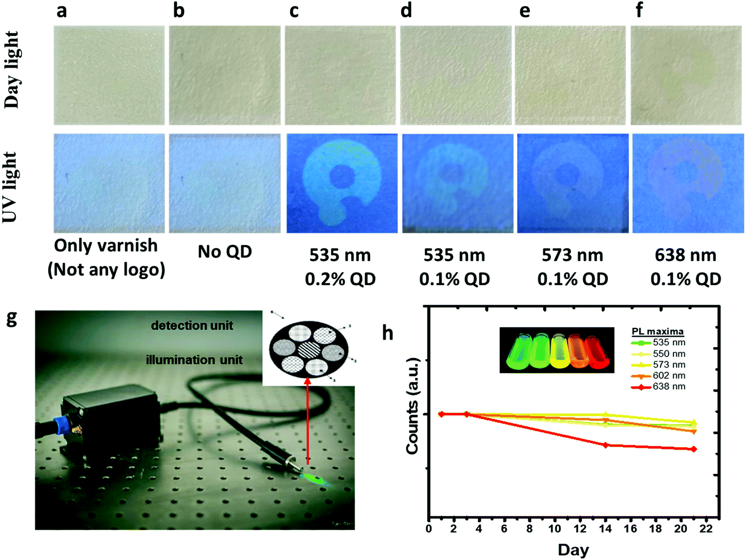 | ||
| Fig. 9 (a–f) The security patterns created with fluorescent inks with and without nanoparticles printed on paper substrates. The nanoparticle concentrations are provided under the photographs. The security patterns were barely visible under daylight and slightly observable when illuminated by UV light by visual inspection. (g) The photograph shows the Quantag sensor having fiber optics and an integrated laser for excitation and collecting fibers as part of an optical readout unit. (h) The intensity of fluorescent inks (0.1% v/v) monitored by the Quantag sensor for 21 days, demonstrating the photostability of security patterns printed on the paper substrates. The inset in (h) shows emission colors of highly concentrated inks. | ||
The photostability of the ink (0.1% v/v) embedded on the paper substrate was monitored for 21 days by the Quantag sensor. The fluorescence of the security patterns monitored proved that the intensities of the patterns were unchanged, as shown in Fig. 9h. The reduction in the intensity of the red-emitting ink (638 nm) may be explained by some sort of environmental effects on the nanoparticles emitting in this wavelength.
To understand the effect of substrate on the security pattern, the inks were applied to various substrates. The thickness of the patterns screen-printed on polymer and glass substrates was measured using an optical profilometer (Fig. S8, ESI†). The thickness of the patterns was about 4.5 μm. These measurements confirmed that the security patterns form a thin film containing nanoparticles distributed homogeneously on the printed part of the substrates. The particle sizes have no effects on the film thickness. The confocal images are given in Fig. 10 showing some part of the logo patterns printed on the glass and polymer substrates. The logos were observable on the glass and polymer surfaces. These confocal images showed that the logo patterns were homogeneously printed on the substrates. In Fig. S9 (ESI†), the logos printed with red fluorescent ink are imaged by using different objectives. For both polymer and glass substrates, the logos were imaged by using two different emission filters: a channel labeled as polymer channel collecting the emission/scattering coming from the varnish and substrate, and the channel labeled as QD channel collecting the fluorescence emissions of the nanoparticles. These images verify that the nanoparticles are homogeneously dispersed in the ink and uniformly printed on the substrates.
 | ||
| Fig. 10 Confocal images of a part of the printed logos, excited by a Hg lamb, on both glass and polymer substrates. The reaction temperature and the emission wavelength are provided on the left side of each photograph. The objective is 4× and the scale bar embedded in each image is 200 μm. Homogeneous distribution of the nanoparticles dispersed in the varnish are clearly seen. | ||
4. Conclusions
Highly fluorescent In(Zn)P/ZnS/DDT colloidal nanoparticles are synthesized for anticounterfeiting applications. The DDT organic shell enhanced the particle stability and fluorescence brightness. The nanoparticles were homogeneously dispersed in a varnish to formulate colorless security inks. The formulated inks were utilized to create security patterns by applying screen printing techniques on various substrates including paper, polymer, and glass, demonstrating the capability of the ink for anticounterfeiting. The inks are transparent in the daylight, but strongly luminous in five different colors under UV light illumination. The security patterns created on the substrates are slightly visible in the daylight but almost colorless under UV light when the concentration of the nanoparticles was dropped to 0.1% v/v. By using a lower amount of nanoparticles, the formula cost of the ink is substantially reduced. The invisible fluorescent inks as the security codes that cannot be perceived by visual inspection are clearly detectable by a handheld, low-cost optical device (Quantag sensor) that is developed in-house. The Quantag sensor is highly sensitive and selective to predetermined ink colors. The spectral information of the security patterns identified by the Quantag sensor is validated by a commercial fiber optics-based spectrometer. However, the Quantag sensor has an advantage over the fiber-optical spectrometer, providing wavelength selectivity using narrow bandwidth emission filters. In summary, an anticounterfeiting technology is developed by combining invisible fluorescent inks with a hand-held, low-cost optical device to validate authenticity.Author contributions
The manuscript was written by all the authors. All the authors have approved the final version of the manuscript. D. T.: carried out synthesis and characterization of nanoparticles, printed and analyzed security patterns screen-printed on substrates; investigation, methodology, and visualization, and wrote the original draft. S. S. Ü.: imaged the substrates by confocal microscopy and optical profilometer, and visualization and wrote the original draft. S. Ö.: conceptualization, writing – review & editing of the manuscripts, supervision, and research administration.Funding sources
Quantag Nanotechnologies supported this research.Conflicts of interest
There are no conflicts to declare.Acknowledgements
We acknowledge Quantag Nanotechnologies for their support. We also acknowledge IYTE Center for Materials Research for XRD measurements of the nanoparticles.References
- J. Y. Jung, J. Kim, Y. S. Shim, D. Hwang and C. S. Son, Materials, 2020, 13, 12 Search PubMed.
- T. O. Moon, J. Y. Jung and S. Cho, Korean J. Mater. Res., 2020, 30, 406–412 CrossRef.
- M. L. You, M. Lin, S. R. Wang, X. M. Wang, G. Zhang, Y. Hong, Y. Q. Dong, G. R. Jin and F. Xu, Nanoscale, 2016, 8, 10096–10104 RSC.
- J. S. Zhang and M. Q. Ge, J. Rare Earths, 2012, 30, 952–957 CrossRef CAS.
- L. Chen, Y. Zhang, A. Q. Luo, F. Y. Liu, Y. Jiang, Q. Z. Hu, S. F. Chen and R. S. Liu, Phys. Status Solidi RRL, 2012, 6, 321–323 CrossRef CAS.
- H. Huang, J. K. Chen, Y. T. Liu, J. D. Lin, S. X. Wang, F. Huang and D. Q. Chen, Small, 2020, 16, 12 Search PubMed.
- S. X. Wang, J. D. Lin, Y. W. He, J. K. Chen, C. B. Yang, F. Huang and D. Q. Chen, Chem. Eng. J., 2020, 394, 10 Search PubMed.
- J. D. Lin, C. B. Yang, P. Huang, S. X. Wang, M. L. Liu, N. Z. Jiang and D. Q. Chen, Chem. Eng. J., 2020, 395, 8 Search PubMed.
- M. X. Li, W. J. Yao, J. Liu, Q. Y. Tian, L. Liu, J. Ding, Q. W. Xue, Q. Lu and W. Wu, J. Mater. Chem. C, 2017, 5, 6512–6520 RSC.
- K. Cheng, R. Qi, S. Lan, H. Y. Wang, X. F. Zheng, C. Liu, D. D. Jia, L. Cao and D. J. Wang, Dyes Pigm., 2020, 174, 10 CrossRef.
- Z. Fatahi, N. Esfandiari and Z. Ranjbar, J. Anal. Test., 2020, 4, 307–315 CrossRef.
- L. Y. Jiao, M. N. Zhang and H. B. Li, Materials, 2020, 13, 13 Search PubMed.
- L. Ju, W. B. Gao, J. Y. Zhang, T. Y. Qin, Z. Du, L. Sheng and S. X. A. Zhang, J. Mater. Chem. C, 2020, 8, 2806–2811 RSC.
- Y. Liu, F. Han, F. S. Li, Y. Zhao, M. S. Chen, Z. W. Xu, X. Zheng, H. L. Hu, J. M. Yao, T. L. Guo, W. Z. Lin, Y. H. Zheng, B. G. You, P. Liu, Y. Li and L. Qian, Nat. Commun., 2019, 10, 9 CrossRef PubMed.
- R. Platel, L. Vaure, E. Palleau, S. Raffy, F. Guerin, D. Lagarde, R. Cours, C. Marcelot, B. Warot-Fonrose, C. Nayral, F. Delpech and L. Ressier, J. Colloid Interface Sci., 2021, 582, 1243–1250 CrossRef CAS PubMed.
- T. P. Nguyen, T. P. Nguyen, Q. V. Lam and T. B. Vu, Solid State Sci., 2020, 101, 9 CrossRef.
- S. Khan, L. Lorenzelli and R. S. Dahiya, IEEE Sens. J., 2015, 15, 3164–3185 Search PubMed.
- S. M. F. Cruz, L. A. Rocha and J. C. Viana, Flexible Electronics, 2018, ch. 3 DOI:10.5772/intechopen.76161.
- M. Saraf, P. Kumar, G. Kedawat, J. Dwivedi, S. A. Vithayathil, N. Jaiswal, B. A. Kaipparettu and B. K. Gupta, Inorg. Chem., 2015, 54, 2616–2625 CrossRef CAS.
- C. Zhang, X. Li, M. L. Liu, T. T. Li, T. X. Yu, Y. Li, J. Zhang, A. M. Asiri, K. A. Alamry and K. Zhang, J. Alloys Compd., 2020, 836, 7 Search PubMed.
- X. Chen, W. Yao, Q. Wang and W. Wu, Adv. Opt. Mater., 2019, 8, 1901209 CrossRef.
- W. Yao, Q. Tian and W. Wu, Adv. Opt. Mater., 2019, 7, 1801171 CrossRef.
- L. Z. Chen, B. A. Hu, J. Y. Zhang, J. M. Zhang, S. T. Huang, P. Ren, Y. Zou, F. Y. Ding, X. H. Liu and H. B. Li, RSC Adv., 2019, 9, 476–481 RSC.
- M. Zhou, S. Chang and C. Grover, Opt. Express, 2004, 12, 2925–2931 CrossRef CAS PubMed.
- T. Jamieson, R. Bakhshi, D. Petrova, R. Pocock, M. Imani and A. M. Seifalian, Biomaterials, 2007, 28, 4717–4732 CrossRef CAS PubMed.
- M. Henriksen, B. Miller, J. Newmark, Y. Al-Kofahi and E. Holden, Methods Cell Biol., 2011, 102, 161–205 Search PubMed.
- E. M. Janke, N. E. Williams, C. She, D. Zherebetskyy, M. H. Hudson, L. Wang, D. J. Gosztola, R. D. Schaller, B. Lee, C. Sun, G. S. Engel and D. V. Talapin, J. Am. Chem. Soc., 2018, 140, 15791–15803 CrossRef CAS PubMed.
- B. K. Gupta, D. Haranath, S. Saini, V. N. Singh and V. Shanker, Nanotechnology, 2010, 21, 055607 CrossRef PubMed.
- X. J. Fu, G. Q. Li, S. Y. Cai, H. Yang, K. Lin, M. He, J. W. Wen, H. B. Li, Y. B. Xiong, D. Z. Chen and X. H. Liu, Carbohydr. Polym., 2021, 251, 9 CrossRef PubMed.
- F. F. Du, Z. H. Guo, Z. Cheng, M. Kremer, S. M. Shuang, Y. Liu and C. Dong, Nanoscale, 2020, 12, 20482–20490 RSC.
- Z. B. Wang, P. X. Pei, D. J. Bai, S. S. Zhao, X. Y. Ma and W. S. Liu, Inorg. Chem. Front., 2020, 7, 2506–2514 RSC.
- S. X. Wang, J. D. Lin, X. Y. Li, J. K. Chen, C. B. Yang, P. Huang, Y. Cheng and D. Q. Chen, J. Mater. Chem. C, 2020, 8, 16151–16159 RSC.
- W. Zheng, B. Y. Sun, Y. M. Li, R. Wang and Y. L. Xu, Mater. Chem. Front., 2019, 3, 2403–2413 RSC.
- J. Y. Jung, B. K. Song and Y. K. Kim, J. Alloys Compd., 2019, 791, 81–86 CrossRef CAS.
- C. Ippen, B. Schneider, C. Pries, S. Kröpke, T. Greco and A. Holländer, Nanotechnology, 2015, 26, 085604 CrossRef CAS PubMed.
- K. Kim, S. Jeong, J. Y. Woo and C. S. Han, Nanotechnology, 2012, 23, 065602 CrossRef PubMed.
- M. D. Tessier, D. Dupont, K. De Nolf, J. De Roo and Z. Hens, Chem. Mater., 2015, 27, 4893–4898 CrossRef CAS.
- P. Mushonga, M. O. Onani, A. M. Madiehe and M. Meyer, J. Nanomater., 2012, 2012, 1–11 CrossRef.
- E. E. L. Langof, E. Lifshitz, O. I. Micic and A. J. Nozik, J. Phys. Chem. B, 2002, 106, 1606–1612 CrossRef.
- S. B. Brichkin, Colloid J., 2015, 77, 393–403 CrossRef CAS.
- N. Mordvinova, A. Vinokurov, T. Kuznetsova, O. I. Lebedev and S. Dorofeev, Dalton Trans., 2017, 46, 1297–1303 RSC.
- U. T. D. Thuy, P. T. Thuy, N. Q. Liem, L. Li and P. Reiss, Appl. Phys. Lett., 2010, 96, 073102 CrossRef.
- R. P. Brown, M. J. Gallagher, D. H. Fairbrother and Z. Rosenzweig, Langmuir, 2018, 34, 13924–13934 CrossRef CAS PubMed.
- S. Tamang, C. Lincheneau, Y. Hermans, S. Jeong and P. Reiss, Chem. Mater., 2016, 28, 2491–2506 CrossRef CAS.
- W. Shen, H. Tang, X. Yang, Z. Cao, T. Cheng, X. Wang, Z. Tan, J. You and Z. Deng, J. Mater. Chem. C, 2017, 5, 8243–8249 RSC.
- S. Haubold, M. Haase, A. Kornowski and H. Weller, ChemPhysChem, 2001, 2, 331–334 CrossRef CAS PubMed.
- X. Fang, T. Zhai, U. K. Gautam, L. Li, L. Wu, Y. Bando and D. Golberg, Prog. Mater. Sci., 2011, 56, 175–287 CrossRef CAS.
- J. Zhang and H. Gu, Dalton Trans., 2020, 49, 6119–6126 RSC.
- J.-H. Jo, D.-Y. Jo, S.-H. Lee, S.-Y. Yoon, H.-B. Lim, B.-J. Lee, Y. R. Do and H. Yang, ACS Appl. Nano Mater., 2020, 3, 1972–1980 CrossRef CAS.
- J. Lim, W. K. Bae, D. Lee, M. K. Nam, J. Jung, C. Lee, K. Char and S. Lee, Chem. Mater., 2011, 23, 4459–4463 CrossRef CAS.
- F. Pietra, L. De Trizio, A. W. Hoekstra, N. Renaud, M. Prato, F. C. Grozema, P. J. Baesjou, R. Koole, L. Manna and A. J. Houtepen, ACS Nano, 2016, 10, 4754–4762 CrossRef CAS PubMed.
- X. Zhang, H. Lee, J. H. Kwon, E. J. Kim and J. Park, Materials, 2017, 10, 880 CrossRef PubMed.
- F. Angel-Huerta, M. P. González-Araoz, J. S. Arias-Cerón, J. F. Sánchez-Ramírez, J. Díaz-Reyes, J. L. Herrera-Pérez and J. G. Mendoza-Álvarez, J. Mater. Sci.: Mater. Electron., 2018, 29, 15649–15657 CrossRef CAS.
- S. H. Lee, Y. Kim, H. Jang, J. H. Min, J. Oh, E. Jang and D. Kim, Nanoscale, 2019, 11, 23251–23258 RSC.
- L. Li and P. Reiss, J. Am. Chem. Soc., 2008, 130, 11588–11589 CrossRef CAS PubMed.
- C. Xia, J. D. Meeldijk, H. C. Gerritsen and C. de Mello Donega, Chem. Mater., 2017, 29, 4940–4951 CrossRef CAS PubMed.
- Y. A. Alemu, Synthesis, Surface Treatment, and Characterization of Copper Indium Sulfide Quantum Dots, Master of Science, Oregon State University, 2016 Search PubMed.
- M. T. Clarke, F. N. Viscomi, T. W. Chamberlain, N. Hondow, A. M. Adawi, J. Sturge, S. C. Erwin, J.-S. G. Bouillard, S. Tamang and G. J. Stasiuk, Commun. Chem., 2019, 2, 36 CrossRef.
- T. Kim, S. W. Kim, M. Kang and S.-W. Kim, J. Phys. Chem. Lett., 2012, 3, 214–218 CrossRef CAS.
- T. Watanabe, C. Wada, Y. Iso, T. Isobe and H. Sasaki, ECS J. Solid State Sci. Technol., 2017, 6, R75–R80 CrossRef CAS.
- J. Chang and E. R. Waclawik, CrystEngComm, 2013, 15, 5612–5619 RSC.
- S. Feizi, H. Zare and M. Hoseinpour, Appl. Phys. A: Mater. Sci. Process., 2018, 124, 1–7 CrossRef CAS.
- W. Yan, G. X. Bai, R. G. Ye, X. L. Yang, H. Q. Xie and S. Q. Xu, Opt. Commun., 2020, 475, 7 Search PubMed.
- Y. Hua, S. K. Hussain and J. S. Yu, J. Alloys Compd., 2020, 826, 14 CrossRef.
- J. Xu, B. B. Zhang, L. Jia, Y. P. Fan, R. J. Chen, T. H. Zhu and B. Z. Liu, ACS Appl. Mater. Interfaces, 2019, 11, 35294–35304 CrossRef CAS PubMed.
- W. J. Yao, Q. Y. Tian, J. Liu, Q. W. Xue, M. X. Li, L. Liu, Q. Lu and W. Wu, Nanoscale, 2017, 9, 15982–15989 RSC.
- K. S. Nair, P. Abhilash and K. P. Surendran, ACS Omega, 2019, 4, 2577–2583 CrossRef CAS PubMed.
- B. Chen, H. P. Xie, S. Wang, Z. Y. Guo, Y. F. Hu and H. Z. Xie, Luminescence, 2019, 34, 437–443 CrossRef CAS PubMed.
- P. Yang, Z. Q. Zhu, T. Zhang, M. Z. Chen, Y. Z. Cao, W. Zhang, X. Wang, X. Y. Zhou and W. M. Chen, Carbon, 2019, 146, 636–649 CrossRef CAS.
- S. J. Park, J. Y. Park and H. K. Yang, Sens. Actuators, B, 2018, 262, 542–554 CrossRef CAS.
- J. Andres, R. D. Hersch, J. E. Moser and A. S. Chauvin, Adv. Funct. Mater., 2014, 24, 5029–5036 CrossRef CAS.
- Y. L. Liu, K. L. Ai and L. H. Lu, Nanoscale, 2011, 3, 4804–4810 RSC.
- P. Kumar, J. Dwivedi and B. K. Gupta, J. Mater. Chem. C, 2014, 2, 10468–10475 RSC.
- N. M. Sangeetha, P. Moutet, D. Lagarde, G. Sallen, B. Urbaszek, X. Marie, G. Viau and L. Ressier, Nanoscale, 2013, 5, 9587–9592 RSC.
- H. Urey, O. V. Akgun, E. Heves, F. Civitci and B. Can, A Fluorescent substance detection system, Turkey Pat., WO 2016/010494, 2016 Search PubMed.
Footnotes |
| † Electronic supplementary information (ESI) available: DDT effect on photophysical properties and relevant characterization details and supporting photographs; the photo of the screen printing device; the PL spectra of varnish and screen printed paper samples (PDF). See DOI: 10.1039/d1ma00383f |
| ‡ The current address of the author, Seçil SEVİM ÜNLÜTÜRK, is Micro-Electro-Mechanical Systems Research and Application Center (METU-MEMS), Middle East Technical University, Çankaya, 06530, Ankara, Turkey. |
| This journal is © The Royal Society of Chemistry 2021 |