
 Open Access Article
 This Open Access Article is licensed under a
 Creative Commons Attribution 3.0 Unported Licence
Enriching surface oxygen vacancies of spinel Co3O4 to boost H2O adsorption for HER in alkaline media†
Ting
Zhu
 *,
Jun
Pan
,
Ying
Xiao
,
Anqiang
Pan
and
Shuquan
Liang
*
*,
Jun
Pan
,
Ying
Xiao
,
Anqiang
Pan
and
Shuquan
Liang
*
School of Materials Science & Engineering, Central South University, Changsha 410083, Hunan, China. E-mail: zhut0002@csu.edu.cn; lsq@csu.edu.cn
First published on 30th August 2021
Abstract
Oxygen-defective Co3O2.64S0.33 (namely CoO0.88S0.11) particulate spheres (PS) were prepared via the solid-state sulfurization of spinel Co3O4 at 300 °C in an Ar atmosphere. The introduction of sulfur (S) atoms was found to enrich the surface oxygen vacancies (Vso) remarkably in the as-derived CoO0.88S0.11 PS relative to pristine Co3O4 and CoS2, thus offering more active sites for catalytic reactions. Theoretical calculations were also performed to justify that the enrichment of Vso is favorable to boost the adsorption of H2O molecules. As a result, these CoO0.88S0.11 PS with exposed (111) facets demonstrated enhanced electrocatalytic performance in H2 evolution reaction (HER) with a low overpotential (OP) of 83 mV to realize a current density of 10 mA cm−2, and a high turnover frequency (TOF) of 1.589 H2 s−1 was obtained in 1 M KOH aqueous electrolyte.
1. Introduction
Cobalt oxides and sulfides, such as Co3O4, CoO, CoS, Co3S4, Co9S8, and CoS2, have been widely explored in photo/electrochemical energy storage and conversion because of their intrinsic merits of low cost, high availability, and excellent chemical stability.1,2 For example, Co3O4 has been intensively employed as an anode material in lithium ion batteries due to its high theoretical capacity and high reversibility.3–5 As a typical p-type semiconductor, CoO is one of the most studied photocatalysts, which can utilize solar energy for water splitting by engineering the band edges.6,7 Compared to their oxide counterparts, cobalt sulfides usually exhibit higher electroactivity and better electric conductivity, making them more promising in metal ion batteries,8–10 supercapacitors,11–13 and electrocatalysis.14–16 Nano engineering and structural design are considered effective strategies to optimize the physical and chemical properties of cobalt oxides/sulfides,17 because the specific surface area, porous texture, electron transport, and chemical stability of the functional materials can be readily tuned and manipulated, so as to realize high specific capacities, prolonged cycle life, or excellent catalytic rates.18 However, the intrinsic properties of the respective cobalt oxides/sulfides are still not fully explored due to the poor understanding of the mechanisms for charge distribution and transfer in the electrochemical/catalytic process.The electrocatalytic performance of particulate catalysts is highly related to atomic defects, such as oxygen vacancies.19,20 For example, Vso are reported to influence the adsorption of zinc ions on the material surface, whereby the calculated Gibbs free energy of Zn2+ can be altered.21 A recent work has shown that Vso played a complicated role in the PEC process, where Vso can increase the carrier concentration to enhance charge transfer and suppress bulk recombination.22 Engineering of Vso in cobalt oxides has been attractive for electrocatalysis. Wang et al. demonstrated that the presence of Vso in Co3O4 has led to the formation of more Co2+ active centers on the Co3O4 surface, which is significant to improve the catalytic performance.23 In a later work by the same group, they found that Vso are favorable to promote the reconstruction/deprotonation of intermediate Co–OOH˙, providing a strong evidence for the role of Vso in electrocatalytic oxygen evolution reaction (OER).24 Ma et al. prepared defective Co3O4−x by calcining SBA-15 to downshift the conduction bands of the Co 3d orbitals, thus improving the electron transfer for electrocatalytic OER.25 It has been reported that the substitution of chalcogen elements can be used to generate oxygen vacancies in a recent research,26 and the enrichment of oxygen vacancies could be attributed to the extrusion of O by S atoms with a larger atomic radius. By surface engineering of Co3O4, Vso were generated by a deoxygenation process to optimize the band edges and electronic structures, which can facilitate charge transfer during the catalytic process. Though various strategies for Vso have been developed and many exciting results have been reported, controllable enrichment of Vso in spinel Co3O4 by partial S substitution has been rarely performed so far.
In this work, CoO0.88S0.11 PS with enriched Vso were prepared via the solid-state sulfurization of spinel Co3O4 PS at 300 °C in the presence of sulfur (S) powder in Ar gas. Specifically, the generation and preservation of Vso were realized by the introduction of appropriate S species in addition to deoxygenation in Ar gas. As a result, the as-synthesized CoO0.88S0.11 PS with exposed (111) facets exhibited enriched Vso, improved electronic conductivity, and a higher ECSA, relative to pristine Co3O4 and CoS2 that was derived from complete sulfurization. When used as electrocatalysts for HER, these CoO0.88S0.11 PS demonstrated a low OP of 83 mV to realize a current density of 10 mA cm−2 with a small Tafel slope of 80 mV dec−1 (in 1 M KOH aqueous solution), which are much better than those of pristine Co3O4 (168 mV, 196 mV dec−1) or CoS2 (96 mV, 119 mV dec−1). In addition, CoO0.88S0.11 PS can yield a high TOF of 1.589 H2 s−1, suggesting a great potential for practical electrocatalytic application. Density-functional theory (DFT) was also employed to calculate the adsorption energies of H2O molecules at the (111) facets for all the samples to verify the experimental results. CoO0.88S0.11 with enriched Vso exhibited the largest H2O adsorption energy of 0.4 eV (absolute value) among all the samples. This work has provided a new path of Vso engineering for metal oxide electrocatalysts to enhance HER.
2. Experimental section
2.1 Synthesis of the Co3O4 particulate spheres (PS)
The cobalt based precursor (CBP) PS were synthesized via a solvothermal method in an isopropanol (IPA) solution. In a typical synthesis procedure, 2 mmol Co (NO3)2·6H2O was firstly dissolved in 30 mL of IPA by magnetic stirring for 10 min. Next, 1 mL of ethylene glycol (EG) was added to the above solution and the mixture was stirred for another 10 mins. Finally, 3 mg of polyvinyl pyrrolidone (PVP, average molecular mass ∼10![[thin space (1/6-em)]](https://www.rsc.org/images/entities/char_2009.gif) 000 g mol−1) was dissolved into the mixture by magnetic stirring for another 10 min. The obtained transparent lavender solution was transferred into a Teflon lined sealed stainless-steel autoclave and heated at 180 °C for 6 h. The light purple product was washed by a rinse-centrifugation process with ethanol several times. The collected CBP powder was dried in an air-flow oven at 60 °C for 24 h. Co3O4 PS were obtained by annealing the as-obtained CBP PS at 200 °C in a muffle furnace at a heating rate of 1 °C min−1 for 2 h.
000 g mol−1) was dissolved into the mixture by magnetic stirring for another 10 min. The obtained transparent lavender solution was transferred into a Teflon lined sealed stainless-steel autoclave and heated at 180 °C for 6 h. The light purple product was washed by a rinse-centrifugation process with ethanol several times. The collected CBP powder was dried in an air-flow oven at 60 °C for 24 h. Co3O4 PS were obtained by annealing the as-obtained CBP PS at 200 °C in a muffle furnace at a heating rate of 1 °C min−1 for 2 h.
2.2 Synthesis of CoO0.88S0.11 PS
The collected Co3O4 powder (100 mg) was placed at the downstream side of a tube furnace, and sulfur powder (200 mg) was placed at the upstream side of the tube furnace. Then, Co3O4 was heated to 300 °C (heating rate of 3 °C min−1) and reacted for 5 h under an argon (Ar) atmosphere. After the reaction, the tube furnace was allowed to cool down naturally to ambient temperature to collect the CoO0.88S0.11 PS product. In the control experiments, cobalt sulfide (CoS2) PS were obtained using the same sulfurization process of Co3O4 powder but at a higher temperature of 400 °C. Partial sulfurization was also performed at 200, 250, and 350 °C using the same procedure to produce the Co3O4-200, 250, and 300 samples, respectively, which were specifically subjected to ESR measurements.2.3 Materials characterization
All the samples were characterized by scanning electron microscopy (SEM, Quanta FEG 250) equipped with energy dispersive X-ray spectroscopy (EDX), transmission electron microscopy (TEM, Titan G2 60-300) equipped with an elemental mapping system, X-ray diffraction (XRD, Rigaku D/Max 2500, CuKα = 1.5406 Å), and X-ray photoelectron spectroscopy (XPS, ESCALAB250Xi). Room-temperature electronic spin resonance (ESR) spectra were measured using an ESR spectrometer (Bruker A300) at 300 K. The frequency of microwave used is 9.853 GHz with a power of 10.8 mW. The magnetic center field is 3510 G with a sweep width of 100 G. The module amplitude is 1 G with a time constant of 1.25 mS and a sweep time of 19.456 s.2.4 Electrochemical measurements.
(1) Alkaline electrolyte: all the electrocatalytic measurements were carried out using an IVIUM V38120 electrochemical workstation in a three-electrode cell with a 1 M of potassium hydroxide (KOH) aqueous solution as the electrolyte. The saturated calomel electrode (SCE) and graphite rod served as the reference and counter electrodes, respectively. The working electrodes were prepared as follows: 18 mg of catalyst powder, 2 mg of polyvinylidene fluoride (PVDF), and 0.2 mL of N-methyl-2-pyrrolidinone (NMP) were mixed together and then ground for 10 minutes to obtain a homogeneous slurry. The slurry was then pasted homogeneously onto a piece of nickel foam (1 cm × 2 cm, coating area ∼1 cm2, mass loading ∼ 4 mg). Then the as-prepared working electrode was dried in a vacuum oven at 60 °C for 12 h.(2) Acidic electrolyte: the electrochemical experiments were tested in standard three electrode system using an IVIUM V38120 electrochemical workstation, and the electrolyte was an aqueous solution of 0.5 M sulfuric acid (H2SO4). The saturated calomel electrode (SCE) and graphite rod served as the reference and counter electrodes, respectively. The working electrodes were prepared as follows: 4 mg of catalyst and 30 μm of Nafion solution were added to 1 mL of water–ethanol mixture solution (volume ratio of 3:1), and the solution was ultrasonicated for 1 h to form a homogeneous ink. Then 5 μL of the ink was dropped onto a glassy carbon electrode (GCE) with a 3 mm diameter.
Linear sweep voltammetry (LSV) was performed at a scan rate of 5 mV s−1 in a potential window of 0 to −0.5 V versus reversible hydrogen electrode (RHE). Electrochemical impedance spectroscopy (EIS) was performed at the frequency from 0.1 MHz to 0.01 Hz with an amplitude of 5 mV. The current variation with time (i–t curve) under constant voltage was measured for 12 h. To simplify the evaluation, a current density of 10 mA cm−2 was used to compare the OPs for all the samples. Electrochemical surface area (ECSA) measurements were performed within a non-faradaic voltage window ranging from −0.1 to − 0 V (vs. SCE). The lattice parameters of all the samples were obtained from PXRD to calculate the unit lattice volumes. The TOFs were then estimated based on the lattice volume, ECSA, and exchange current density using the following equation:27
2.5 Theoretical calculations
The calculations were conducted using density functional theory (DFT) with the Perdew–Burke–Ernzerhof (PBE) form of generalized gradient approximation functional (GGA).2 The Vienna ab initio simulation package (VASP)28,29 was used to calculate the exchange–correlation interaction of Co (3d74s2), O (2s22p4), S (3s23p4), and H(1s1) valence electrons with the plane wave energy cutoff at 400 eV. The gamma-centered K-point meshes were set as 3 × 3 × 3 for Co3O4 and CoS2 bulk, and 2 × 2 × 1 for Co3O4(111) surface, CoO0.88S0.11(111) surface, and CoS2(111)surface. The energy (converged to 1.0 × 10⁻⁶ eV per atom) and force (converged to 10−3 eV Å−1) were set as the convergence criteria for geometry optimization.We have obtained the XRD results of Co3O4 (JCPDS no. 74-2120: a = b = c = 0.8400 nm, space group Fd![[3 with combining macron]](https://www.rsc.org/images/entities/char_0033_0304.gif) m), and CoS2 (JCPDS no. 89-1492: a = b = c = 0.5506 nm, space group PA), and thus the basic crystal models of Co3O4, CoO0.88S0.11, and CoS2 can be illustrated. The (111) facets of all the samples were identified from the XRD and HRTEM images. In all the optimization for structural calculations, the atoms of the bottom layers were fixed, while the positions of the other atoms were allowed to relax. A vacuum layer as large as 15 Å was used along the c direction normal to the surface to avoid periodic interactions. Oxygen vacancies are formed by deleting oxygen atoms. In the Co3O4 (111) surface model, there are 40 Co atoms, 48 O atoms, and 16 H atoms (for the bottom passivation). If one oxygen atom is deleted, there is one oxygen vacancy, and the percentage of oxygen vacancy is 100 × (1/48)%. If two oxygen atoms are deleted, there are two oxygen vacancies, and the percentage is 100 × (1/24)%. For the defective CoS2 (111), one of the surface S atom was removed to simulate the S vacancy.
m), and CoS2 (JCPDS no. 89-1492: a = b = c = 0.5506 nm, space group PA), and thus the basic crystal models of Co3O4, CoO0.88S0.11, and CoS2 can be illustrated. The (111) facets of all the samples were identified from the XRD and HRTEM images. In all the optimization for structural calculations, the atoms of the bottom layers were fixed, while the positions of the other atoms were allowed to relax. A vacuum layer as large as 15 Å was used along the c direction normal to the surface to avoid periodic interactions. Oxygen vacancies are formed by deleting oxygen atoms. In the Co3O4 (111) surface model, there are 40 Co atoms, 48 O atoms, and 16 H atoms (for the bottom passivation). If one oxygen atom is deleted, there is one oxygen vacancy, and the percentage of oxygen vacancy is 100 × (1/48)%. If two oxygen atoms are deleted, there are two oxygen vacancies, and the percentage is 100 × (1/24)%. For the defective CoS2 (111), one of the surface S atom was removed to simulate the S vacancy.
The chemisorption energies of H2O on the (111) facets are described as follows:
Based on the crystalline structures, the calculations of adsorption energies were carried out for the (111) facets with Co–O or Co–S terminals. Adsorption sites for perfect surfaces, one, and two units of O or S vacancies were built to simulate the surfaces with no defect or enriched defects.
3. Results and discussion
A schematic of the transformation from spinel Co3O4 to CoO0.88S0.11 with enriched Vso by S atom substitution via solid-state sulfurization is displayed in Fig. 1a. At an elevated temperature, sublimation of sulfur powder takes place and the S species enter the spinel structure of Co3O4, and then replace partial O atoms at the solid–gas interface. As a result, more O (R = 0.074 nm) atoms are squeezed out of the crystalline structure due to the much larger atomic radius of S (R = 0.102 nm), thus forming CoO0.88S0.11 with enriched oxygen vacancies at the surface. It should be noted that the crystalline structure is not altered after introduction of S species because a slight surface sulfurization is employed herein (recall experimental details). | ||
| Fig. 1 Schematic crystalline structures of spinel Co3O4 and the derived CoO0.88S0.11 with enriched surface oxygen vacancies by S substitution (a), and diagrams of H2O adsorption sites (b–d) for Co3O4 (111) with one unit of O vacancy (b), CoO0.88S0.11 (111) with two units of O vacancies (c), and CoS2 (111) with one unit of S vacancy (d). | ||
It has been reported that the presence of surface defects is important to promote the intrinsic properties of catalysts. As for electrocatalytic water splitting, adsorption of H2O molecules at the catalyst surface is the dominant step in the HER process. Thus, DFT calculations were then performed to compare the H2O adsorption energies of the (111) facets (will be discussed in XRD and HR-TEM later) for all the three samples. The detailed calculation parameters are described in the experimental part, and corresponding simulation models are presented in Fig. S1 (ESI†). Fig. 1b–d show the diagrams of the adsorption sites (ads) of Co3O4 (111) with Co–O terminals, CoO0.88S0.11 (111) with Co–O terminals, and CoS2 (111) with Co–S terminals, respectively. Specifically, each Co atom at site 1 of Co3O4 (111) is bonded with four O atoms, and contains one unit of O vacancy, as shown in Fig. 1b. Similarly, each Co atom at site 1 of CoO0.88S0.11 (111) in Fig. 1c is bonded with two O and one S atoms, and contains two units of O vacancies (denoting enriched Vso). Meanwhile for CoS2 (111), each Co atom at site 1 is bonded with three S atoms, and contains one unit of S vacancy. The calculation results have revealed that the adsorption energies (ΔEads) at sites 1 for Co3O4, CoO0.88S0.11, and CoS2 are −0.25, −0.40, and −0.15 eV, respectively. Significantly, CoO0.88S0.11 (111) with one unit of O vacancy also shows a larger ΔEads of −0.39 eV, compared to its Co3O4 and CoS2 counterparts (more calculations shown later). A larger absolute number of ΔEads suggests a more stable adsorption of H2O molecules at the catalyst surface, which is favorable to expedite the HER process. These calculations have preliminarily implied the importance of surface sulfurization with enriched Vso for improving electrocatalytic performance.
Following our theoretical and experimental methods, cobalt based materials were then synthesized and characterized. Cobalt based precursor (CBP) PS were prepared using a solvothermal process (SEM images shown in Fig. S2, ESI†). Next, the as-synthesized CBP PS were transformed to Co3O4 through a heat treatment at 200 °C in air, which were subsequently used for partial or complete sulfurization. As the typical sample of this work, CoO0.88S0.11 PS were examined by SEM and EDX, as shown in Fig. 2. From the SEM results, monodispersed spheres with uniform particle size (∼2 μm) can be observed (Fig. 2a and b). A magnified SEM image in Fig. 2c reveals that a particle is composed of nanosheets with a porous texture. The overall morphology of the PS is well retained after partial sulfurization, compared to SEM results of Co3O4 PS (Fig. S3a–c, ESI†). A complete sulfurization from Co3O4 to CoS2 has led the conversion of nanosheets to aggregated particles, as shown in Fig. S3d–f (ESI†). Then, the EDX information of the typical sample in Fig. 2d was captured from the area indicated by the yellow rectangle in Fig. 2c, which confirms the presence of Co, O, and S elements (atomic ratio is roughly at 1:0.88:0.11, hence denoted as CoO0.88S0.11) in the PS. In addition, elemental mappings were performed to find out the distributions of Co, O, and S, as shown in Fig. 2e–g. It can be seen that Co and O signals are almost overlapped, while S shows a slightly larger area than Co and O, suggesting a partial surface sulfurization of the pristine Co3O4 particles.
 | ||
| Fig. 2 SEM images (a–c), EDX (d), and elemental mappings (e–g) of the as-prepared CoO0.88S0.11 PS. | ||
The detailed structural, compositional, and electronic features were further investigated by TEM and ESR. Fig. 3a displays an individual CoO0.88S0.11 PS, in which a hollow interior can be clearly observed. The magnified TEM image in Fig. 3b indicates that PS are composed of porous nanosheet structures, suggesting a high surface area of the material. Fig. 3c shows the HRTEM image which was taken from the area indicated by a yellow oval in Fig. 3b. The lattice spacings of 0.57 and 0.28 nm can correspond to Co3O4 (111) and (220), respectively.30 Notably, the spacing of (111) was enlarged from the usual ∼0.46 nm to 0.57 nm, which should be caused by the substitution of O by S with a larger atomic radius. In addition, a lattice distortion of ∼17° is observed for the (111) planes, demonstrating that the introduction of S heteroatoms may have deformed the periodic crystalline structure of Co3O4. The TEM and HR-TEM images were also obtained and presented for pristine Co3O4 and CoS2 (Fig. S4, ESI†), which clearly reveal the high exposure of Co3O4 (111) and CoS2 (111). To confirm the existence of Vso, ESR tests were carried out for pristine Co3O4, CoS2, and the partially sulfurized Co3O4 samples at different temperatures, respectively. The ESR spectra in Fig. 3d clearly show that CoO0.88S0.11 (Co3O4-300) delivers a much higher signal than Co3O4 or CoS2 at g = 2.004, which indicates the appearance of oxygen vacancies.31 Unexpectedly, CoS2 exhibited only a bit higher signal than pristine Co3O4, which suggests that complete substitution of O with S may have changed the crystalline structure, thus causing the oxygen vacancies to vanish. In addition, it is interesting to find that lower sulfurization temperatures (Co3O4-200 and 250) failed to generate a large number of Vso, whereas higher temperature (Co3O4-350) was not favorable to preserve the O vacancies.
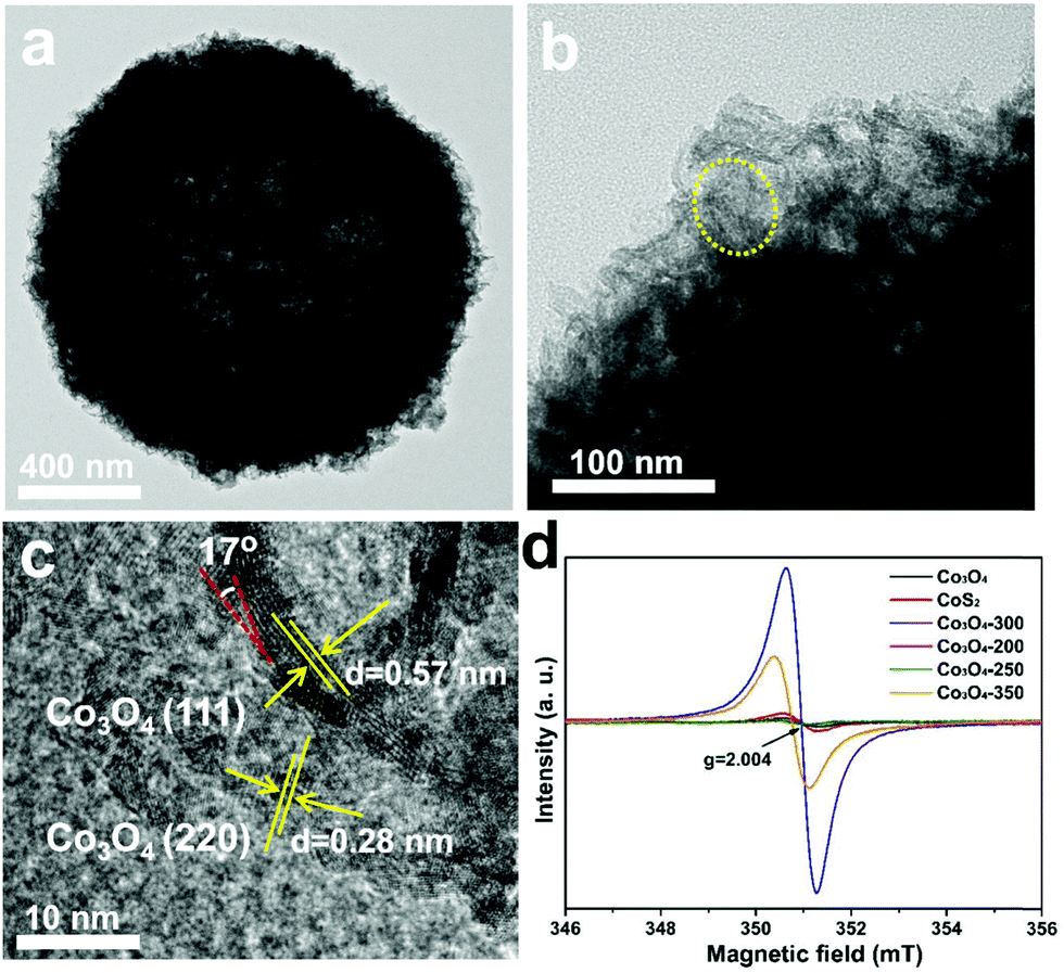 | ||
| Fig. 3 TEM (a and b) and HRTEM (c) images of CoO0.88S0.11 PS, and the ESR results (d) of pristine Co3O4, CoS2, and the partially sulfurized Co3O4 at different temperatures (Co3O4-300 is CoO0.88S0.11); the signal at g = 2.004 corresponds to the O vacancies. | ||
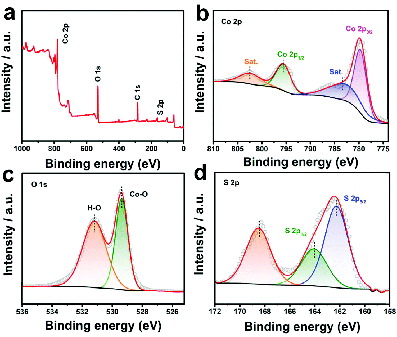
The XRD patterns of all the three samples are displayed in Fig. S5 (ESI†). All the peaks recorded from 10–80° (Fig. S5a, ESI†) for Co3O4 can be assigned to spinel Co3O4 (JCPDS no. 74-2120),32 while all the identified peaks for CoS2 should be assigned to cubic CoS2 (JCPDS no. 89-1492).33 For CoO0.88S0.11, only peaks of Co3O4 can be matched, indicating that the crystalline phase is not altered under such a slight sulfurization. However, slight shifts can still be distinguished in the diffraction peaks for all the XRD peaks of CoO0.88S0.11. For example, as shown in the magnified region in Fig. S5b (ESI†), the peak of Co3O4 (311) was shifted from 36.86° to 36.78° after partial sulfurization, which should be caused by the replacement of the O positions by S atoms. In addition, it can be calculated that the unit cell parameter of CoO0.88S0.11 is 0.8098 nm, which has been reduced compared to that of Co3O4. To further examine the chemical composition and status of the typical sample CoO0.88S0.11, XPS was carried out and the results are shown in Fig. 4. The survey spectrum in Fig. 4a confirms again the presence of Co, O, and S. The paired peaks of 779.7 and 795.7 eV shown in Fig. 4b can be attributed to Co 2p3/2 and Co 2p1/2, respectively, corresponding to the characteristic spin orbitals of Co3+.34 Co3+ has shifted toward lower binding energies after partial sulfurization compared to pristine Co3O4 (781.1 and 796.4 eV, respectively, Fig. S6a, ESI†), which is consistent with a previous work that demonstrates oxygen defects in Co3O4.35 In addition, the presence of two satellite peaks centered at around 786 and 803 eV, respectively, should be attributed to the Co2+ oxidation state, which indicates that part of Co3+ has been reduced to Co2+ during the formation of Vso.36 There are two binding energies for O 1s (Fig. 4c), which can be assigned to Co–O (529.3 eV),37 and O− (531.2 eV) related to oxygen vacancies,38 respectively. Both Co–O and O− shifted to lower binding energies compared to those of pristine Co3O4 (530.7 and 532 eV, respectively, Fig. S6b, ESI†). The XPS peaks located at 162.3 and 164 eV (Fig. 4d) should be ascribed to S 2p3/2 and S 2p1/2, respectively.39 The broad peak at 168.6 eV can be assigned to S–O bond associated with SOx.40 Fig. S7 (ESI†) shows the XPS results of the CoS2 sample, in which strong peaks of S–O bonds (oxidized S, 168–170 eV) can be distinguished. Combining the results of TEM, XRD, and XPS analyses, we have demonstrated that S species were introduced into the lattice of Co3O4 without altering the crystalline phase. However, S atoms may replace O positions in the Co3O4 crystal structure, and thus induce the generation of Vso with lattice distortion, which is essential to increase the intrinsic catalytic activity.
 | ||
| Fig. 4 XPS survey spectrum (a), Co 2p (b), O 1s (c), and S 2p (d) of the as-prepared CoO0.88S0.11 PS. | ||
The HER properties were evaluated for all the samples using a standard three-electrode configuration in 1 M KOH. In an alkaline electrolyte, the HER process can proceed as the following Volmer–Heyrovsky and Volmer–Tafel reactions (1)–(3):41
| H2O + e− → H* (Volmer step) | (1) |
| H* + H2O + e− → H2 (Heyrovsky step) | (2) |
| H* + H* → H2 (Tafel step) | (3) |
The reactions start with the adsorption of H2O molecules on the catalyst surface to generate H* via the Volmer-step reduction process. Next, H2 molecules will be formed by the electrochemical bonding of H2O with H* (Heyrovsky step), or through the chemical combination of two H* (Tafel step). By increasing the adsorption energy and reducing the dissociation energy barrier, the HER process can be efficiently facilitated in the presence of Vso.42 In this work, H2O adsorption energies in the presence of O vacancies in different samples have been studied using DFT calculations (more results and discussion later).
Fig. 5a shows the LSV curves of all the samples. The OPs at a current density of 10 mA cm−2 for Co3O4, CoS2, CoO0.88S0.11, and Pt/C are recorded as 168, 96, 83, and 23 mV, respectively. Additionally, an OP of 329 mV is required for CoO0.88S0.11 to realize a current density of 100 mA cm−2, which is the best performance among all the three samples (all the data are iR corrected). Tafel slopes are used to describe the catalytic kinetics of electrocatalysts, and a smaller Tafel slope usually represents faster kinetics. Tafel slopes of 196, 119, 80, and 32 mV dec−1 were calculated for samples Co3O4, CoS2, CoO0.88S0.11, and Pt/C, respectively (Fig. 5b). The LSV curves of the partially sulfurized samples obtained at 200, 250, and 350 °C were also collected, using which the OPs were calculated to be 176, 151, and 113 mV, respectively (Fig. S8, ESI†). To evaluate the stability of the materials in an acidic electrolyte, electrochemical measurements were also carried out in a sulfuric acid aqueous solution (0.5 M H2SO4), and results have been shown in Fig. S9 (ESI†). The OPs at a current density of 10 mA cm−2 for the samples Co3O4, CoS2, and CoO0.88S0.11 are determined to be 205, 157, and 116 mV (Fig. S9a, ESI†), respectively, while Fig. S9b (ESI†) shows that the Tafel slopes of Co3O4, CoS2, and CoO0.88S0.11 are 180, 121, and 87 mV dec−1, respectively. As a comparison, a summarization table (Table S1, ESI†) listing similar HER electrocatalysts reported in the previous work is also provided, revealing that the electrocatalytic performance of this work is comparable to those reported in recent years.
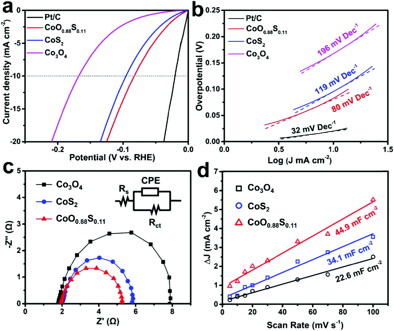 | ||
| Fig. 5 LSV curves (a), Tafel plots (b), EIS (c), and ECSA (d) of the as-prepared Co3O4, CoS2, and CoO0.88S0.11 samples. LSV and Tafel slope of Pt/C electrode are also shown as a comparison. | ||
To further study the difference in the HER process of all the three samples, EIS and ECSA measurements were performed and the results were plotted. It can be seen from Fig. 5c that all the Nyquist plots show similar semicircles, from which transfer resistances of 6.2, 4.0, and 3.3 Ω can be calculated for Co3O4, CoS2, and CoO0.88S0.11, respectively. The inset in Fig. 5c shows an equivalent circuit, which contains constant phase element (CPE), electrolyte resistance (Rs), and charge transfer resistance (Rct). The smallest Rct value of CoO0.88S0.11 suggests its best electronic conductivity among all the samples, which verified its best HER performance. Next, CV tests (Fig. S10, ESI†) were conducted in a non-faradaic potential region (−0.1 to 0 V, vs. SCE) to estimate the ECSA for the samples (Fig. 5d). Accordingly, the double-layer capacitances (Cdl) for Co3O4, CoS2, and CoO0.88S0.11 are estimated to be 22.6, 34.1, and 44.9 mF cm−2, respectively. The ECSA is considered positively proportional to Cdl, and thus CoO0.88S0.11 holds the largest ECSA among all the samples. Catalytic materials with higher surface areas usually show better electrocatalytic performance, because they can provide larger numbers of active sites for catalytic reactions.43,44 Turnover frequency (TOF) indicates the numbers of gaseous H2 molecules evolved in the HER process at a unit time, which is regarded as the most important parameter to reflect the intrinsic catalytic properties. Herein, the TOFs of all the three samples were calculated and compared according to a calculation method described in a previous work.27 CoO0.88S0.11 yielded a TOF of 1.589 H2 s−1, which is much higher than those of Co3O4 (0.307 H2 s−1) or CoS2 (0.806 H2 s−1).
Electrocatalytic stability is considered important for practical application. Durability tests were performed with respective OPs to maintain a current density of 10 mA cm−2 for all the three samples. The obtained results (Fig. 6) show that the current densities of both Co3O4 and CoS2 decrease upon catalytic time, but CoS2 keeps a higher current than Co3O4. Remarkably, CoO0.88S0.11 has shown a much more stable current density after 2 h compared to the other samples, which suggests that it possesses the best durability among all the three samples. Apparently, a quick current decay of Co3O4 was observed after 2 h, which should be due to its poor conductivity, and the mass loss of the electrode materials during the prolonged cycles.45 After 12 h, current densities of 8.91, 7.62, and 6.33 mA cm−2 can be retained for samples CoO0.88S0.11, CoS2, and Co3O4, respectively, indicating the lowest current decay of 10.9% for CoO0.88S0.11.
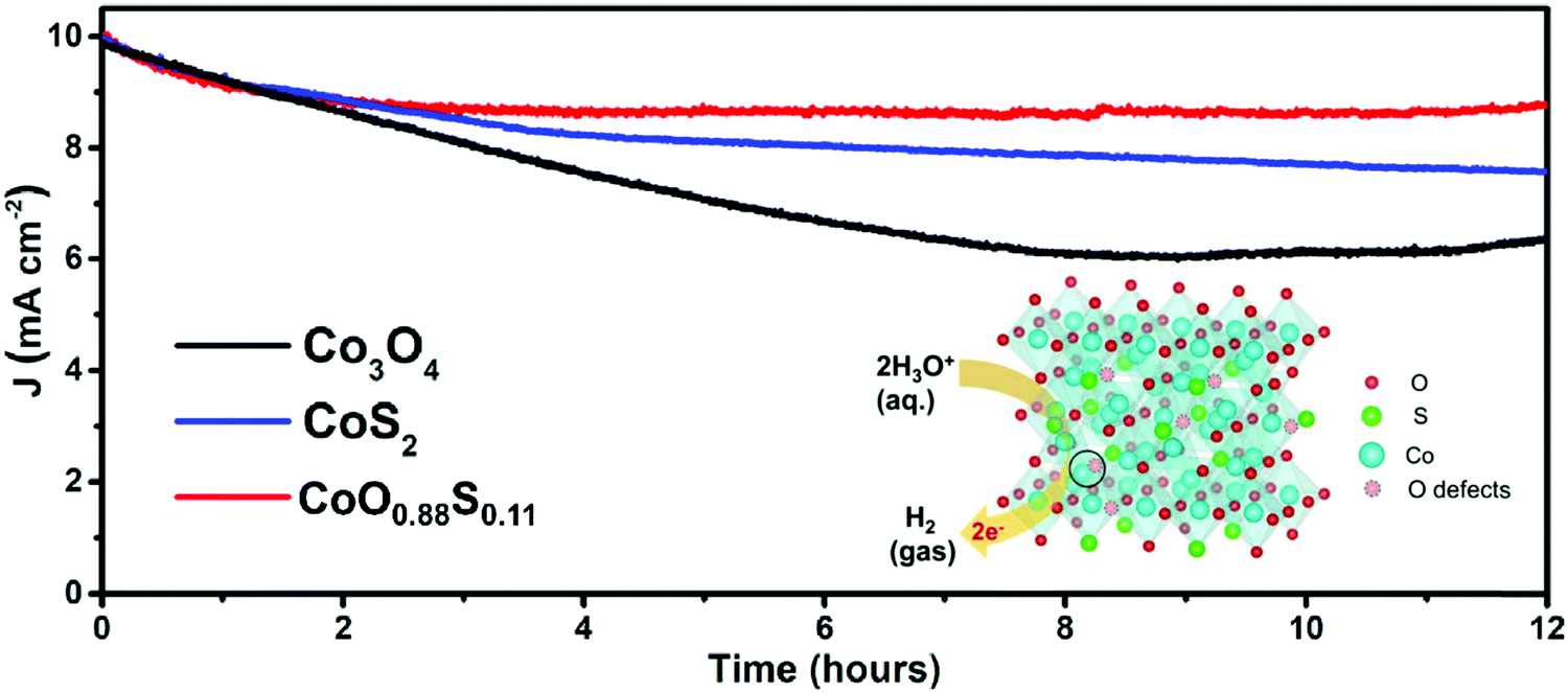 | ||
| Fig. 6 i–t curves obtained under the respective OPs of the three samples in 1 M of KOH aqueous solution. The inset schematically shows a HER process enhanced by enriched Vso of CoO0.88S0.11. | ||
The inset in Fig. 6 shows a schematic illustration of the HER process that has been promoted by enriched Vso of CoO0.88S0.11. The Co atoms serve as the main active sites for catalytic reactions, where water molecules are reduced to generate H2. Additionally, Vso present at the lattice of the spinel structure (Co atom and Vso indicated by the solid circle) can act as extra active centers for absorbance of H2O and subsequent reduction. Thus, electrocatalytic H2 evolution can be strengthened by such an enhancement. Furthermore, the LSV curves of all the three samples after stability tests were also obtained, as shown in Fig. S11 (ESI†). The results indicate that the catalytic activities of the samples Co3O4 and CoO0.88S0.11 are improved after durable tests (reduced OPs for η100), while a decay of catalytic properties can be observed for CoS2, which is probably due to its relatively low chemical stability.
The electrocatalytic results have shown that CoS2 is superior over Co3O4. To further study the role of Vso in the H2O adsorption process, DFT calculations were then extended to simulate the perfect (111) facets without any defects for all the three samples. Fig. 7 showcases the ΔEads results at sites 1 for Co3O4 (111) with Co–O terminals (Fig. 7a), CoO0.88S0.11 with Co–O terminals (Fig. 7b), and CoS2 (111) with Co–S terminals (Fig. 7d), respectively. The absolute values of adsorption energies are in the order of (Co3O4, 0.18 eV) < (CoO0.88S0.11, 0.23 eV) < (CoS2, 0.28 eV). Hence, CoS2 (111) exhibits the most stable adsorption for H2O molecules among all the three samples based on a perfect crystalline structure mode. However, our previous ESR results (recall Fig. 3d) have confirmed a remarkable Vso enrichment in the CoO0.88S0.11 sample, compared to the pristine Co3O4 or CoS2. Then the ΔEads at site 1 was also calculated for CoO0.88S0.11 (111) with one unit of O vacancy. Interestingly, the absolute value of ΔEads was increased from 0.23 to 0.39 eV, which is much higher than that of CoS2. There results strongly validated that the presence and enrichment of vacancies can play a very significant role in the adsorption of water molecules.
 | ||
| Fig. 7 Diagrams of H2O adsorption sites for the (111) facets without any defects (a, b, and d) for Co3O4 (a), CoO0.88S0.11 (b), and CoS2 (d), respectively, and that of CoO0.88S0.11 (111) with one unit of O vacancy (c). | ||
In addition, further calculations for adsorption sites 2 with perfect lattices have obtained the ΔEads values of −0.03, −0.27, and −0.66 eV for Co3O4, CoO0.88S0.11, and CoS2, respectively, which suggests that CoS2 is a very good electrocatalytic candidate for HER. However, in fact it is very difficult to remove all the defects within the crystalline structures. For CoS2 (111), the ΔEads of site 1 decrease to −0.15 eV when there is one unit of S vacancy, compared to −0.28 eV obtained without any defects. Therefore, a proper S substitution of Co3O4 by partial and slight sulfurization to enrich surface defects reported herein is a rational strategy to optimize the intrinsic catalytic properties.
4. Conclusions
In summary, CoO0.88S0.11 electrocatalysts with enriched Vso were prepared via a partial sulfurization process of spinel Co3O4 with exposed (111) facets. The introduction of S atoms into the crystalline lattice of spinel Co3O4 has led to the generation and preservation of lattice distortion with Vso. The as-formed CoO0.88S0.11 PS with Vso exhibit a higher ECSA and better electronic conductivity compared to pristine Co3O4 and CoS2. The DFT calculations have verified that enriched Vso can significantly increase the adsorption energies of H2O during the HER process. In virtue of the presence of Vso, high ECSA, and good charge transfer properties, CoO0.88S0.11 PS have demonstrated a low OP (η10 = 83 mV) with an enhanced TOF (1.589 H2 s−1) for HER when used as an electrocatalyst for water splitting. This research work provides a new path for surface defect engineering of cobalt based materials with improved physical and chemical properties as efficient electrocatalysts.Author contributions
T. Zhu conceived the idea and designed the experiments; J. Pan carried out the experiments, and collected and analyzed the data; Y. Xiao, A. Q. Pan, and S. Q. Liang provided assistance in analyzing the data; T. Zhu wrote the manuscript and S. Q. Liang provided assistance in the revision; T. Zhu and S. Q. Liang provided financial support to this work.Conflicts of interest
The authors declare no conflict of interest.Acknowledgements
This work was financially supported by the start-up grant of Central South University (No. 202045001), Innovation-Driven Project of Central South University (No. 2019CX028), the Huxiang Assembly Program for High-level Talents (Department of Science and Technology of Hunan province, China, No. 2018RS3018), and the National Natural Science Foundation of China (Key Program, No. 51932011). The authors also thank Prof. Lei Han from Hunan University for his valuable comments and discussion.References
- X. Y. Yu and X. W. Lou, Adv. Energy Mater., 2018, 8, 1701592 CrossRef.
- X. F. Lu, S. L. Zhang, E. B. Shangguan, P. Zhang, S. Y. Gao and X. W. Lou, Adv. Sci., 2020, 7, 2001178 CrossRef CAS.
- Y. G. Li, B. Tan and Y. Y. Wu, Nano Lett., 2008, 8, 265–270 CrossRef CAS.
- Z. S. Wu, W. C. Ren, L. Wen, L. B. Gao, J. P. Zhao, Z. P. Chen, G. M. Zhou, F. Li and H. M. Cheng, ACS Nano, 2010, 4, 3187–3194 CrossRef CAS.
- D. L. Wang, Y. C. Yu, H. He, J. Wang, W. D. Zhou and H. D. Abruna, ACS Nano, 2015, 9, 1775–1781 CrossRef CAS.
- L. B. Liao, Q. H. Zhang, Z. H. Su, Z. Z. Zhao, Y. N. Wang, Y. Li, X. X. Lu, D. G. Wei, G. Y. Feng, Q. K. Yu, X. J. Cai, J. M. Zhao, Z. F. Ren, H. Fang, F. Robles-Hernandez, S. Baldelli and J. M. Bao, Nat. Nanotechnol., 2014, 9, 69–73 CrossRef CAS.
- W. L. Shi, F. Guo, C. Zhu, H. B. Wang, H. Li, H. Huang, Y. Liu and Z. H. Kang, J. Mater. Chem. A, 2017, 5, 19800–19807 RSC.
- T. Chen, Z. W. Zhang, B. R. Cheng, R. P. Chen, Y. Hu, L. B. Ma, G. Y. Zhu, J. Liu and Z. Jin, J. Am. Chem. Soc., 2017, 139, 12710–12715 CrossRef CAS.
- H. C. Li, H. C. Yang, Z. H. Sun, Y. Shi, H. M. Cheng and F. Li, Nano Energy, 2019, 56, 100–108 CrossRef CAS.
- B. L. Guan, S. Y. Qi, Y. Li, T. Sun, Y. G. Liu and T. F. Yi, J. Energy Chem., 2021, 54, 680–698 CrossRef.
- Z. Y. Gao, C. Chen, J. L. Chang, L. M. Chen, P. Y. Wang, D. P. Wu, F. Xu and K. Jiang, Chem. Eng. J., 2018, 343, 572–582 CrossRef CAS.
- C. Li, J. Balamurugan, N. H. Kim and J. H. Lee, Adv. Energy Mater., 2018, 8, 1702014 CrossRef.
- H. Y. Wang, Y. Yang, Q. H. Li, W. Lu, J. Q. Ning, Y. J. Zhong, Z. Y. Zhang and Y. Hu, Sci. China-Mater., 2021, 64, 840–851 CrossRef CAS.
- S. J. Deng, Y. Zhong, Y. X. Zeng, Y. D. Wang, X. L. Wang, X. H. Lu, X. H. Xia and J. P. Tu, Adv. Sci., 2018, 5, 1700772 CrossRef.
- H. J. Xu, J. Cao, C. F. Shan, B. K. Wang, P. X. Xi, W. S. Liu and Y. Tang, Angew. Chem., Int. Ed., 2018, 57, 8654–8658 CrossRef CAS.
- L. H. Li, L. Song, H. Guo, W. Xia, C. Jiang, B. Gao, C. Wu, T. Wang and J. P. He, Nanoscale, 2019, 11, 901–907 RSC.
- X. Wang, Y. Chen, Y. J. Fang, J. T. Zhang, S. Y. Gao and X. W. Lou, Angew. Chem., Int. Ed., 2019, 58, 2675–2679 CrossRef CAS.
- J. Joo, T. Kim, J. Lee, S. I. Choi and K. Lee, Adv. Mater., 2019, 31, 1806682 CrossRef.
- S. Liu, C. Chen, Y. Zhang, Q. Zheng, S. Zhang, X. Mu, C. Chen, J. Ma and S. Mu, J. Mater. Chem. A, 2019, 7, 14466–14472 RSC.
- H. Zhang, J. Zhang, Y. Li, H. Jiang and C. Li, J. Mater. Chem. A, 2019, 7, 13506–13510 RSC.
- T. Xiong, Z. G. Yu, H. J. Wu, Y. H. Du, Q. D. Xie, J. S. Chen, Y. W. Zhang, S. J. Pennycook, W. S. V. Lee and J. M. Xue, Adv. Energy Mater., 2019, 9, 1803815 CrossRef.
- Z. L. Wang, X. Mao, P. Chen, M. Xiao, S. A. Monny, S. C. Wang, M. Konarova, A. J. Du and L. Z. Wang, Angew. Chem., Int. Ed., 2019, 58, 1030–1034 CrossRef CAS.
- L. Xu, Q. Q. Jiang, Z. H. Xiao, X. Y. Li, J. Huo, S. Y. Wang and L. M. Dai, Angew. Chem., Int. Ed., 2016, 55, 5277–5281 CrossRef CAS.
- Z. H. Xiao, Y. C. Huang, C. L. Dong, C. Xie, Z. J. Liu, S. Q. Du, W. Chen, D. F. Yan, L. Tao, Z. W. Shu, G. H. Zhang, H. G. Duan, Y. Y. Wang, Y. Q. Zou, R. Chen and S. Y. Wang, J. Am. Chem. Soc., 2020, 142, 12087–12095 CrossRef CAS.
- H. Y. Zeng, M. Oubla, X. P. Zhong, N. Alonso-Vante, F. Du, Y. Xie, Y. H. Huang and J. W. Ma, Appl. Catal., B, 2021, 281, 119535 CrossRef CAS.
- A. Karmakar, K. Karthick, S. Kumaravel, S. S. Sankar and S. Kundu, Inorg. Chem., 2021, 60, 2023–2036 CrossRef CAS.
- B. Dutta, Y. Wu, J. Chen, J. Wang, J. K. He, M. Sharafeldin, P. Kerns, L. Jin, A. M. Dongare, J. Rusling and S. L. Suib, ACS Catal., 2019, 9, 456–465 CrossRef CAS.
- O. Bokanowski, I. Schindler and H. Zidani, Nonlinear Anal.: Theory Methods Appl., 1999, 35, 1073–1090 CrossRef.
- E. J. Baerends, Theor. Chem. Acc., 2000, 103, 265–269 Search PubMed.
- Y. Y. Lu, W. W. Zhan, Y. He, Y. T. Wang, X. J. Kong, Q. Kuang, Z. X. Xie and L. S. Zheng, ACS Appl. Mater. Interfaces, 2014, 6, 4186–4195 CrossRef CAS.
- A. Janotti and C. G. Van de Walle, Appl. Phys. Lett., 2005, 87, 122102 CrossRef.
- Y. Z. Liu, X. W. Chi, Q. Han, Y. X. Du, J. Q. Huang, X. H. Lin and Y. Liu, Nanoscale, 2019, 11, 5285–5294 RSC.
- D. Ma, B. Hu, W. D. Wu, X. Liu, J. T. Zai, C. Shu, T. T. Tsega, L. W. Chen, X. F. Qian and T. L. Liu, Nat. Commun., 2019, 10, 3367 CrossRef.
- J. J. Zhu, K. Kailasam, A. Fischer and A. Thomas, ACS Catal., 2011, 1, 342–347 CrossRef CAS.
- Z. C. Wang, W. J. Xu, X. K. Chen, Y. H. Peng, Y. Y. Song, C. X. Lv, H. L. Liu, J. W. Sun, D. Yuan, X. Y. Li, X. X. Guo, D. J. Yang and L. X. Zhang, Adv. Funct. Mater., 2019, 29, 1902875 CrossRef.
- Y. C. Wang, T. Zhou, K. Jiang, P. M. Da, Z. Peng, J. Tang, B. A. Kong, W. B. Cai, Z. Q. Yang and G. F. Zheng, Adv. Energy Mater., 2014, 4, 1400696 CrossRef.
- L. W. Chen, X. Zuo, S. J. Yang, T. M. Cai and D. H. Ding, Chem. Eng. J., 2019, 359, 373–384 CrossRef CAS.
- W. B. Hu, Y. Liu, R. L. Withers, T. J. Frankcombe, L. Noren, A. Snashall, M. Kitchin, P. Smith, B. Gong, H. Chen, J. Schiemer, F. Brink and J. Wong-Leung, Nat. Mater., 2013, 12, 821–826 CrossRef CAS.
- N. Yao, P. Li, Z. R. Zhou, R. Meng, G. Z. Cheng and W. Luo, Small, 2019, 15, 1901993 CrossRef.
- Y. J. Fang, D. Y. Luan, Y. Chen, S. Y. Gao and X. W. Lou, Angew. Chem., Int. Ed., 2020, 59, 2644–2648 CrossRef CAS.
- Y. P. Lei, Y. C. Wang, Y. Liu, C. Y. Song, Q. Li, D. S. Wang and Y. D. Li, Angew. Chem., Int. Ed., 2020, 59, 20794–20812 CrossRef CAS.
- Z. Cai, Y. M. Bi, E. Y. Hu, W. Liu, N. Dwarica, Y. Tian, X. L. Li, Y. Kuang, Y. P. Li, X. Q. Yang, H. L. Wang and X. M. Sun, Adv. Energy Mater., 2018, 8, 1701694 CrossRef.
- Q. C. Wang, Y. P. Lei, Y. C. Wang, Y. Liu, C. Y. Song, J. Zeng, Y. H. Song, X. D. Duan, D. S. Wang and Y. D. Li, Energy Environ. Sci., 2020, 13, 1593–1616 RSC.
- Y. P. Lei, Q. C. Wang, S. J. Peng, S. Ramakrishna, D. Zhang and K. C. Zhou, Adv. Energy Mater., 2020, 10, 1902115 CrossRef CAS.
- Y. L. Tong, H. Q. Liu, M. Z. Dai, L. Xiao and X. Wu, Chin. Chem. Lett., 2020, 31, 2295–2299 CrossRef CAS.
Footnote |
| † Electronic supplementary information (ESI) available. See DOI: 10.1039/d1ma00566a |
| This journal is © The Royal Society of Chemistry 2021 |