
 Open Access Article
 This Open Access Article is licensed under a Creative Commons Attribution-Non Commercial 3.0 Unported Licence
The rational design of inorganic and organic material based nanocomposite hybrids as Na-ion battery electrodes
Rangaswamy
Puttaswamy
a,
Nataraj Sanna
Kotrappanavar
 *ab and
Debasis
Ghosh
*a
*ab and
Debasis
Ghosh
*a
aCentre for Nano & Material Sciences, Jain University, Jain Global Campus, Bangalore 562112, India. E-mail: g.debasis@jainuniversity.ac.in; debasisghosh88@gmail.com; sk.nataraj@jainuniversity.ac.in
bIMDEA Water Institute, Avenida Punto Com, 2. Parque Científico Tecnológico de la Universidad de Alcalá, Alcalá de Henares, 28805 Madrid, Spain
First published on 28th June 2021
Abstract
The past decade has witnessed significant research interest in rechargeable Na-ion batteries (SIBs). Compared to Li-ion batteries (LIBs), SIBs promise to be much more cost-effective, thanks to the high abundance of sodium, and they are capable of providing energy densities close to LIBs when the cost is normalized. However, although promising, conventional SIB electrodes suffer from low capacities/poor rate capabilities due to slow Na+ diffusion kinetics and inferior cycle lives due to structural and phase instability. To mitigate these issues, much effort has been devoted towards designing composite electrodes, where the components can synergistically boost the capacities, rate capabilities, and cycling stabilities. While the rational design of electrodes has been able to overcome certain hurdles relating to SIB technology, summarizing coherent approaches for addressing issues in this field is important in order to direct the future sustainable and economic development of commercially viable high-performance electrodes. In this review, we have summarized recent advances relating to the rational design of carbonaceous and non-carbonaceous nanocomposites involving different inorganic and organic materials for SIB applications. Synthesis strategies, synergistic interactions, and electrochemical performance data are summarized. Existing issues are covered and potential solutions for designing better electrodes are also proposed.
 Rangaswamy Puttaswamy | Rangaswamy P completed his doctoral work in chemistry at Kuvempu University, India in 2020. His doctoral research was focused on the synthesis and electrochemical studies of electrode materials for energy storage applications, such as lithium- and sodium-ion batteries. Currently he is working as a Senior Research Associate at the Centre for Nano and Materials Science, Jain University, India. His current research is focused on electrode materials for aqueous metal ion batteries. |
 Nataraj Sanna Kotrappanavar | Dr S. K. Nataraj is currently working as a Professor at the Centre for Nano and Material Sciences (CNMS), Jain University, Bangalore, India. He obtained his PhD in 2008 in polymer science from Karnatak University, Dharwad, India. Immediately after the completion of his PhD, he pursued three Postdoctoral Associate assignments at Chonnam National University, South Korea (2007–2009), the Institute of Atomic Molecular Sciences, Academia Sinica (2009–10), Taiwan, and Cavendish Laboratory, University of Cambridge, UK (2010–2013). He was awarded the DST-INSPIRE Faculty Award (2013–2015) at CSIR-CSMCRI, Bhavnagar. His main area of interest is the development of sustainable materials and processes for energy and environmental applications, including water treatment. |
 Debasis Ghosh | Dr Debasis Ghosh (PhD, IIT Kharagpur, 2014) has been working on electrochemical energy storage for the last 10 years. Before joining the Centre for Nano and Material Sciences, Jain University, Bangalore in 2017 as an Assistant Professor, he was appointed as a postdoctoral fellow at KAIST in South Korea and at the University of Waterloo, Canada. The current research interests of his research group include rechargeable batteries (metal-ion, metal–sulfur, and metal–air), supercapacitors, and the design of multifunctional electrocatalysts for OER/ORR/HER applications. |
1. Introduction
In a world of ever-more innovative and sophisticated gadgets that are used to simplify human efforts, energy sockets are constantly changing shape, size, and design to accommodate new energy storage sources. At present, rechargeable Li-ion batteries (LIBs) are the most reliable power source for many gadgets, owing to their high energy densities, high durability, lack of memory effects, and low self-discharge rates.1–4 Ever since the first commercial example in 1991, LIBs have been exploited to extract maximum output performance from the component materials involved. Over the years, innovation in the field of LIBs has led to the extraction of performances close to the maximum capabilities. However, the limited availability of Li in the face of ever-increasing energy demands is the biggest concern relating to the sustainability of this technology, and this is forcing researchers and technologists to investigate alternative monovalent and multivalent metal-ion batteries, moving “beyond Li ions”.5–10 Among the limited alternative emerging possibilities available for adoption, rechargeable sodium-ion batteries (SIBs) stand out as the most promising technology owing to the high theoretical capacity of sodium (1166 mA h g−1), its high abundance (it is practically inexhaustible and less susceptible to supply risk),11–13 its environmental friendliness, and low battery management costs. Most significantly, the abundance of Na in comparison to Li makes SIBs economically viable, and they are easy to process14 and safer to package into devices.Despite the promising features, the practical use of SIBs is restricted by several factors,11,14,15 such as poor capacities, low initial Coulombic efficiencies, poor rate capabilities, inferior cycle lives, etc. The poor electrochemical performance of SIBs arises mainly due to the much larger radius of Na+ (1.02 Å) compare to Li+ ion, resulting in poor intercalation kinetics,16,17 with rigid inner inorganic frameworks imposing significant challenges when it comes to designing suitable hosts to accommodate Na+. Although conversion-type or alloyed electrode (Table 1) materials exhibit higher initial capacities, the high structural strain caused by pulverization and phase changes causes degradation of the active materials, resulting in poor cycle lives.18 On the other hand, electrodes based on organic materials, although offering high theoretical capacities and facile Na+ insertion paths due to tuneable structural design abilities, are plagued with electrolyte solubility issues.19,20 Furthermore, both conventional organic and inorganic material based electrodes suffer from poor electronic conductivity,21–23 which restricts charge transfer and results in poor electrochemical performance, especially at high charge/discharge rates.
| Electrode materials for sodium-ion batteries | |
|---|---|
| Intercalation-type mechanism | NaxMo2O4, Na4Ti5O12, NaFePO4, NaTi2(PO4)3, NaVPO4F, Na3V2(PO4)3, Na3V2(PO4)2F3, Na3V2(PO4)2FO2, Na2Fe2(SO4)3, Na2+2xFe2−x(SO4)3, V2O5, VO2, Na2/3Ni1/3Mn2/3O2, Na2Ti3O7, NaMO2 (M = Ti, V, Cr, Ni, Fe, Co, Mn), NaMnO2, NaMPO4 (M = Mn, Fe, Co, Ni), Na2FePO4, NaNi0.5Ti0.5O2, Na2FePO4F, Nb2O5, MXenes, NaTiO2, NaMnPO4, NaNiO2, NaFeSO4F, NaFeO2, NaCrO2, NaxNiO2, NaxCoO2, Na2/3(Ni1/3Fe1/3Mn2/3)O2, Na[Mn1/2Fe1/2]O2, Na2/3[Fe1/2Mn1/2]O2, NaMn1/2Fe1/2O2, Na2/3Mn1/2Fe1/2O2, P2-Na2/3(Fe1/2Mn1/2)O2, NaMn3O5, Na2/3Co1/3Ti2/3O2, Na1/2Co2/3Mn1/3O2, P2-Na1/3Ni1/3Mn2/3O2, NaNi1/3Mn1/3Fe1/3O2, Na2/3Fe1/2Mn1/2O2, Na2/3[Ni1/3Mn2/3]O2, Na2Ti6O13, Na2Ti2O5, Fe2(MoO4)3, Na2FeP2O7, Na4Fe(CN)6, Na2Ti7O15, Na2Ti2O4(OH)2, Na0.85Li0.17Ni0.21Mn0.64O2, Na2FeP2O7, Na4Mn9O18, CuHCF, Na2M[Fe(CN)6] (M = Mn, Fe, Co, Ni, Cu), Na4Mn4Ti5O18 |
| Conversion-type mechanism | Fe2S, MoO2, FeSe2, NiS2, ZnSe, MoO3, CuS, Cu2P2O7, MnFe2O4, MgFe2O4, NiP3, CuF2, CoF2, MnF2, FeF2, MnS, CoO, MnO, CuNCN, ZnNCN, CaV4O9, CoFe2O4 |
| Alloy-based mechanisms | Sb@Co(OH)2, Sn–Ge, Co–Sn, Sn–Fe, Sn–Cu, Sn–Ni, Co3Sn2, Mo3Sb7, Bi–Sb, Sn–P, Bi0.94Sb1.06S3, Bi2S3, Bi2O3, Sn50Ge25Sb25, Sn10Bi10Sb80, Zn4Sb3, FeSb2 |
| Intercalation- and conversion-based mechanism | Co9S8, MoS2, V2O3, Co0.8Se, Cu2S@MOS2, Ni3S2–Co9S8, TiO2@MoS2, VS2, WS2, FeF3·0.5H2O, Fe2F5·H2O, FeOxF2−x, MF3 (M = Ti, V, Mn, Fe, and Co), FeFx, NaFeF3, FeO0.7F1.3, Cu3(PO4)2, FeV2O4, NiSe2, Ni3V2O8 |
| Conversion- and alloy-based mechanism | Si, P, Pb, Ge, Sb, SnS, Sb2O3, Fe3O4, Sb2S3, SnO2, CuO, Co9Se8, SnSe2, GeS2, SnS–ZnS, Co9S8–ZnS, Ni2P–ZnP4, Sn4P3, Se4P4, CuP2, CoP4, MoP, FeP4, CoSe2, CoS2, FeS2, MOSe2, Sb2Te3, SeTe, Cu3P, SnP3, Co3O4, Fe2O3, Sb2O4 |
| Intercalation-, conversion- and alloy-based mechanism | Sb2Se3, In2S3–Sb2S3 |
| Displacement reaction | CuWO4, CuNCN, ZnNCN |
Therefore, developments in the field of SIBs have been hindered as the search for combinations of highly electrochemically active materials and rational designs continues. Researchers are particularly looking for nanomaterial-based engineered composite electrodes with higher numbers of storage sites, improved conductivities, and flexible architectures, which can directly influence the capacities, rate capabilities, and cycling stabilities.24–28 Cutting the size of the active material down to few nanometers accompanied by rational design in terms of nanocomposite formation, with controlled structural features and architectures, has been found to be an effective strategy to mitigate the aforementioned problems of limited achievable capacities, poor rate capabilities, and inferior cycling stabilities related to SIBs. Nanostructured active materials with 0D, 1D, and 2D architectures offer large electroactive surfaces for charge storage and accelerate the reaction kinetics via significantly reducing the diffusion path lengths for Na+ ions/electrons. In addition, 3D architectures are beneficial for maintaining structural integrity. Suitably designed nanoarchitectures with interior void spaces29 not only offer highly active surfaces with reduced diffusion path lengths for Na+ ions but there is also room for volume expansion, thus enhancing the cycling stability.30–32
The rational design of nanocomposite electrodes often involves: (i) directing the heterogeneous growth of a nanostructured active material on a conducting flexible carbon support, such as structurally modified graphene, carbon nanotubes (CNTs), carbon fibers (CFs), etc.; (ii) the in situ modification/confinement of active materials with an appropriate conducting matrix; or (iii) adopting multi-functional nanocomposite hybrids of two or more active materials (carbonaceous or non-carbonaceous), which can synergistically enhance the electrochemical performance of the electrode. The task-specific design of nanocomposite electrodes comprising one or more active materials with or without a conducting carbonaceous support offers several advantages over the use of bare active materials, owing to a synergistic effect from each component reducing the limitations of SIBs. For example, nanocomposites of active materials with carbonaceous supports allow the nanostructures to be connected through a conductive network, ensuring easy charge propagation and improving the electrode kinetics. In addition, the hierarchical porous nature of a conductive matrix in a nanocomposite can significantly enhance the penetration of electrolyte ions, ease ion diffusion, and influence the charge-storage kinetics with an enhanced capacitive contribution.33,34 The heteroatom doping of a carbon structure with a large amount of nanocrystalline graphite can also improve both intercalation and the adsorption capacity.35 Furthermore, such carbonaceous nanocomposites also provide flexible architectures to buffer volume changes during cycling, improving the structural integrity and preventing the agglomeration of active material during continuous charging/discharging.36–38 These materials also exhibit facile film-forming properties and can be used as binder-free electrodes.39 In addition, the rational design of nanocomposites with two or more active materials without a carbon support can also result in improved electronic, mechanical, and electrochemical properties because of the heterogeneous structure/interface and can synergistically improve the charge storage, rate performance, and cycling stability. For such nanocomposites, rational design is even more important, since the components are chosen with specific roles aimed towards charge storage and providing structural stabilization with room to accommodate pulverization during cycling.
Recent years have seen a large number of publications, including a few review articles, focusing on the design and development of electrode materials for SIBs. However, most of these have focused on a particular class of electrode material, e.g., polyanion-type electrodes,22,40,41 polymeric carbonyls,42–44 metal selenides,45 metal–organic frameworks,46–48 iron oxides and chalcogenides,49 phosphate frameworks,50 hard carbon-based electrodes,51,52etc. However, inorganic/organic or MOF-type electrodes cannot provide the desired energy densities alone due to certain issues mostly arising from structural dissolution, poor conductivity, etc. Thus, the fabrication of high-performance electrodes often requires the coherent design of constituent materials in the form of nanocomposite hybrids with carbonaceous materials. Recently, a few review articles have discussed in detail the use of nanocomposite electrodes for SIBs.30,31,53 Liang et al.54 gave comprehensive details of carbonaceous (graphene, CNT, carbon fiber) and non-carbonaceous material-based nanocomposite anodes for use in SIBs. Wasalathilake et al.55 mainly focused on the synthesis processes and a mechanistic overview of Na+ storage in different forms of graphene and their nanocomposites via different intercalation paths. On the other hand, Wang et al.14 focused mainly on the Na+ storage mechanisms relating to graphene and metal oxides, and their nanocomposite anodes.
Herein we present a comprehensive review of the recent developments relating to the rational design of carbonaceous (chemically synthesized carbon and biomass-derived carbon) and non-carbonaceous nanocomposites of different inorganic (metal-oxides/chalcogenides/phosphates/sulfates) and organic (carbonyl/carboxylate/hydroxyl/polymer) materials, MOF-derived nanocomposites, and organic–inorganic hybrid nanocomposite electrodes for SIB applications. A key consideration is synthesis strategies and favorable synergistic interactions for developing high-performance stable electrodes. Based on a comprehensive analysis of rationally designed composite materials, future key considerations for the design of high-performance SIB electrodes have been proposed. A schematic illustration of different synthesis approaches and types of composites/hybrids for next-generation SIBs is shown in Fig. 1.
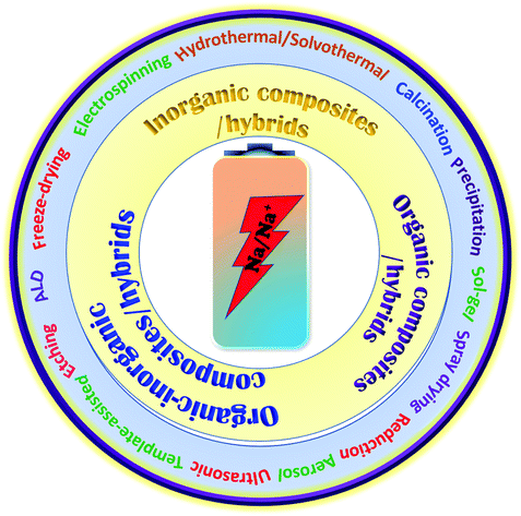 | ||
| Fig. 1 A schematic illustration of the different types of composites/hybrids and fabrication methods for next-generation SIBs. | ||
2. Inorganic composite materials
The commercialization of SIB electrodes so far involves quite a limited choice of electrodes. It is very important to maximize the active surface area of the electrode to allow large amounts of charge accumulation while maintaining a conducting network throughout the material for facile charge transport. Although nanosized materials reduce the ionic diffusion time, improving the rate performance, engineering nanostructures with a suitable conducting matrix can result in improved capacities, rate capabilities, and cycling stabilities through favorable synergetic cooperation. However, it is crucial to control the growth of nanostructures on the conducting phase or the confinement in a 3D conductive network with good dispersion and intimate interfacial contact, as these are decisive factors relating to electrochemical performance. Several datasets in this regard are available for evaluating reported improved structural features and electrochemical performance as a result of favorable synergetic effects. This section attempts to summarize the parameters associated with adopting hybrids of carbonaceous materials with different metal oxides/chalcogenides (MxCy, C = O, S, Se, Te), phosphides, and sulfates to overcome the drawbacks of Na+ storage when using bare inorganic electrodes.2.1. Metal oxide/chalcogenide (MxCy, C = O, S, Se, Te) based composite materials
Metal oxides or chalcogenides (MxCy, C = O, S, Se, Te) in general are cost-effective and offer high theoretical capacities; however, their insulating nature and structural strain due to large volume changes during the continuous charge–discharge process can limit the rate capabilities and cycling stabilities of electrodes based on these materials.56–58 Real-world SIB design requires suitable synthetic approaches, aimed at improving the electrical conductivity and structural integrity, and enhancing the electrochemical performance through favorable synergetic effects.37,58A yolk–shell architecture, constructed with an active material core and a protective conductive carbon hollow shell, provides unique morphological features and physicochemical properties, overcoming drawbacks relating to the volume expansion and structural degradation of SIB electrodes. Such nanostructures are often synthesized via conventional self-templating approaches, which include Ostwald ripening, the partial removal of the core from a core–shell structure, surface-protected etching, etc. Most yolk–shell nanoarchitectures investigated as SIB electrodes use the Ostwald ripening growth mechanism, which includes the dissolution of small crystals and the redeposition of dissolved species on the surfaces of larger crystals.59 For instance, Zhang et al. developed nitrogen-doped yolk-like TiO2 (∼0.8 V vs. Na/Na+) wrapped with a carbon shell60via a solvothermal process followed by calcination with much-improved storage capacity and cycling stability compared with TiO2 solid spheres. The growth of the TiO2 spherical core structure followed the Ostwald ripening mechanism, including the formation of nascent TiO2 nuclei via an alcoholysis reaction, followed by seed growth and aggregation. Finally, the well-defined yolk–shell (YS) structure is accomplished using diethylenetriamine, which facilitates the core dissolution, shell recrystallization, and re-deposition processes. The anode material (AM) core-conducting NC shell structure showed a significant improvement in performance, with a specific capacity of 242.7 mA h g−1 at 0.5C, it maintained a considerable capacity of 115.9 mA h g−1 even at a high current of 20C (∼7.5 times higher than that of TiO2 solid spheres), and it exhibited good cycling stability, with capacity retention of 95.5% over 3000 cycles even at a high current of 24C. Qiu et al.61 reported a similar YS structure consisting of a TiO2 core and furfural pyrolytic carbon shell synthesized via a self-catalyzing solvothermal process followed by calcination. Thanks to the conducting shell and voids for accommodating volume expansion, the YS architecture reported outstanding rate performance at a rate of 40C and excellent cycle life, with 85% capacity retention over 2000 cycles, which is far superior to bare TiO2. Jun Liu et al. reported an eggette-like Sn@C yolk–shell nanoarchitecture62via facile self-assembly followed by carbonization/reduction strategies to achieve tin cores covered with a carbon membrane network. The large void space effectively buffers the volume variations of Sn, and the carbon membrane network provides abundant diffusion pathway, enhances the electrode kinetics, and prevents the aggregation of Sn. Distinctive robust yolk–shell NiS2 nanoparticle (NP) embedded CFs (NiS2⊂PCF)63 were successfully fabricated and used as a high-performance flexible electrode in SIBs. The fabrication process and corresponding fibrous architecture of the NiS2⊂PCF material are schematically demonstrated in Fig. 2a and b. Briefly, porous carbon fibers (PCFs) were subjected to hydrophilic treatment and immersed in concentrated Ni(NO3)2 solution (step 1). The PCFs loaded with Ni(NO3)2 were transformed into Ni⊂PCF via annealing at 1000 °C for 1 h (step 2), and subsequent sulfuration of as-obtained Ni⊂PCF was carried out at 160 °C for 10 h to form the NiS2⊂PCF material (step 3). The 3D NiS2⊂PCF anode (∼1.4 V vs. Na/Na+) showed a capacity as high as 679 mA h g−1 at 0.1C, excellent cycling performance, with 76% capacity retention over 5000 cycles, and excellent rate performance (245 mA h g−1 at 10C) with a high reversible capacity, even in different bending states (Fig. 2c).
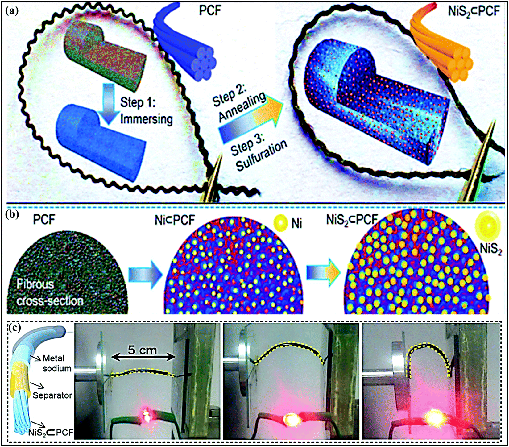 | ||
| Fig. 2 (a) A schematic illustration of the fabrication procedure, (b) a cross-sectional view of the structural evolution of flexible NiS2⊂PCF, and (c) a schematic illustration of the constructed structure of a flexible fiber-shaped SB and photos of LEDs lit using the as-assembled fiber-shaped SB in different bending states. Reproduced with permission.63 Copyright: 2018, Wiley-VCH Verlag GmbH & Co. KGaA. | ||
Wu et al.64 demonstrated an interface-modulated two-step sintering strategy (450 °C for 2 h under an Ar atmosphere followed by annealing at 270 °C for 3 h in air) to fabricate a Co3O4@C dodecahedron YS structure starting from a MOF (ZIF 67). The YS Co3O4@C anode electrode demonstrated excellent rate capabilities with a high capacity of 307 mA h g−1 at 1 A g−1 and 269 mA h g−1 at 2 A g−1 thanks to the conducting carbon shell. Sb@C nanoconfined N/S co-doped 3D carbon microspheres (Sb@NS-3DPCMSs)65 that could undergo ultralong high-rate cycling were fabricated via a salt-templating directed spray-drying process combined with a continuous multi-step thermal treatment approach, and the formation of the yolk–shell structure was confirmed via first-principles simulations. The formation of the yolk–shell architecture provided enough space to buffer volume expansion, improving the structural integrity with a long cycle life (a capacity of 331 mA h g−1 was retained even after 10![[thin space (1/6-em)]](https://www.rsc.org/images/entities/char_2009.gif) 000 cycles at a high rate of 20 A g−1). The empty carbon box with abundant pores enhanced the conductivity and improved the electrode kinetics, and the co-dopants improved the intercalation kinetics and capacity (the 3D architecture showed a specific capacity of ∼540 mA h g−1 at 100 mA g−1).
000 cycles at a high rate of 20 A g−1). The empty carbon box with abundant pores enhanced the conductivity and improved the electrode kinetics, and the co-dopants improved the intercalation kinetics and capacity (the 3D architecture showed a specific capacity of ∼540 mA h g−1 at 100 mA g−1).
Recently, yolk–shell structured ZnCo2O4 spheres fabricated with rGO via an electrostatic interaction process,66 also demonstrated superior electrochemical performance in both LIBs and SIBs. As an anode (∼0.75 V vs. Na/Na+) in SIBs, ZnCo2O4@rGO reported a dominant non-faradaic contribution (89.2% at a scan rate of 1 mV s−1) with a discharge capacity of 280 mA h g−1 after 1000 cycles at 1 A g−1. The enhanced performance of unique yolk–shell ZnCo2O4@rGO is mainly due to its unique morphology, which induces rapid electrode kinetics via enhancing electrode/electrolyte interactions and shortening the Li+/Na+ diffusion distance. On the other hand, rGO effectively buffers the large volume variations and improves the cycle life via maintaining the structural integrity of the material. In another example, MOF-derived Co9S8@C yolk–shell nanocages67 were prepared and a direct conversion mechanism was demonstrated via first-principles calculations and various spectroscopic techniques. The unique composite, where the Co9S8 NPs anode is dispersed in an amorphous carbon matrix, improved the overall electrochemical performance via accelerating the conversion reactions, improved the electrode kinetics via reducing the Na+-diffusion distance, and provided buffering against volume variations during cycling.
The other most widely followed approach to fabricate YS architectures is the template approach, which involves a series of steps, including the fabrication of the AM core, coating with a sacrificial template, a second coating of the outer layer, which can be carbonized to fabricate the outer thin carbon layer, and finally removing (via chemical etching, calcination, or solvent dissolution) the sacrificial template to create an inner void.59 For instance, Junjie Cai et al. fabricated yolk-double shell cube-like SnS@N–S co-doped carbon (YDSC-SnS@NSC) via a self-templating, selective etching, and self-assembly process.68 Details of yolk-double shell formation are given in Fig. 3a. The formation of a robust double-shell structure with void space provided strong buffering against SnS volume variations. The outer carbon shells prevent aggregation and maintain structural integrity during cycling, and highly conductive S and N doped into the carbon shell improve the electrical conductivity and speed up the charging kinetics. Benefiting from these merits, the YDSC-SnS@NSC anode (∼0.9 V vs. Na/Na+) in SIBs was reported to have a stable cycle life of over 1500 cycles with capacity retention of 83.5% and exceptional rate performance, with a discharge capacity of 257 mA h g−1 even at 8 A g−1.
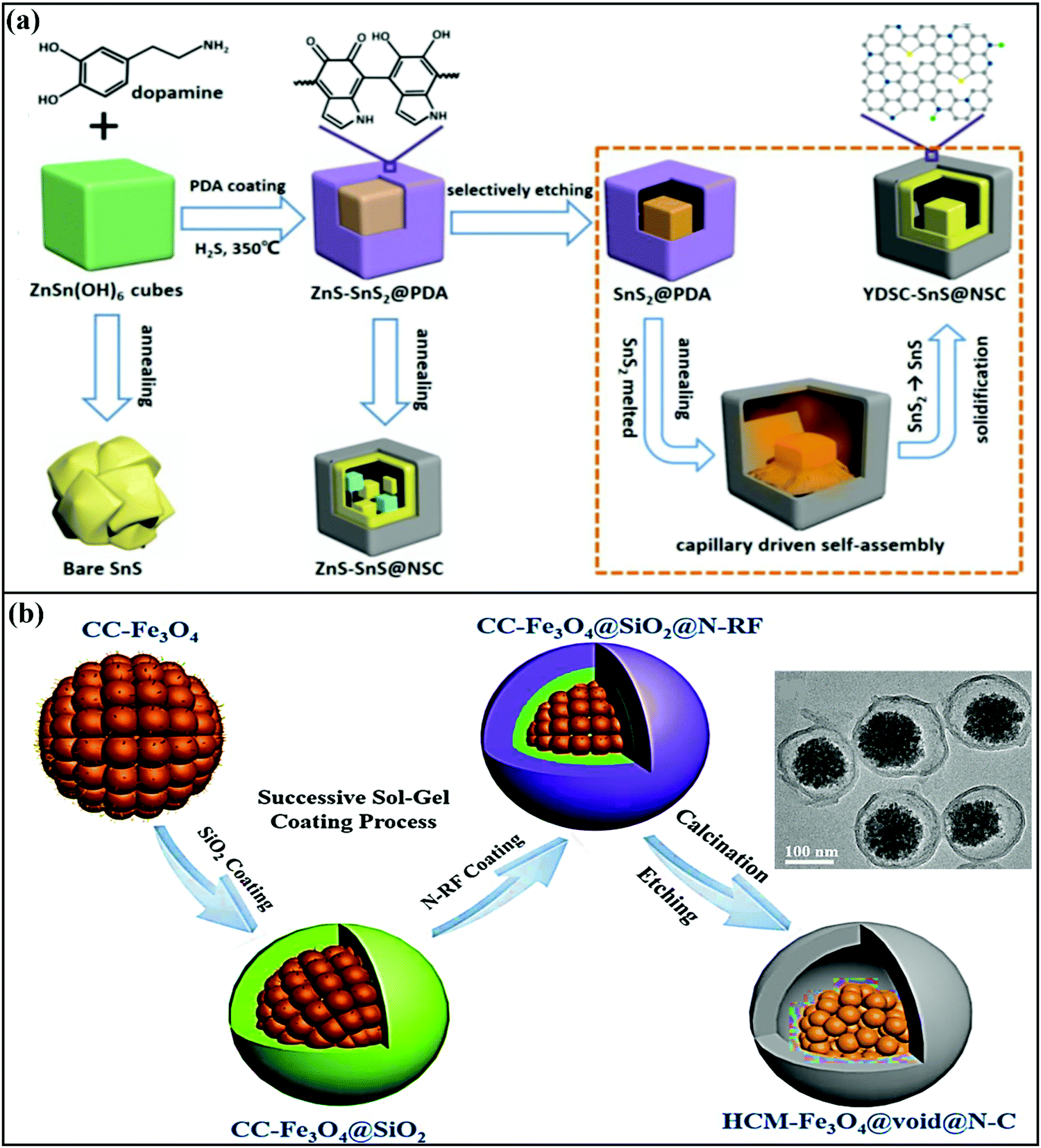 | ||
| Fig. 3 (a) A schematic diagram of the synthesis of YDSC-SnS@NSC via a self-templating, selective etching, and heat and capillary induced self-assembly process. Reproduced with permission.68 Copyright: 2019, American Chemical Society. (b) A schematic illustration of the synthesis of yolk–shell structured Fe3O4/N-doped carbon nanospheres with highly crystallized mesoporous Fe3O4 cores (HCM-Fe3O4@void@N–C) (inset: a TEM image of HCM-Fe3O4@void@N–C nanospheres). Reproduced with permission.57 Copyright: 2019, Elsevier. | ||
Zhao et al. demonstrated a highly crystalline mesoporous Fe3O4 yolk with a nitrogen-doped resorcinol formaldehyde pyrolytic N-doped carbon shell, with a silica interlayer as a sacrificial template.57 The typical yolk–shell structure prepared via a sol–gel approach followed by calcination (Fig. 3b) displayed an average particle size of around 200 nm with an N-doped carbon shell thickness of ∼15 nm, which was accompanied by the presence of large void space to accommodate volume changes. With an intercalation- and conversion-based mechanism, the composite anode (∼0.8 V vs. Na/Na+) reported a capacity of ∼372 mA h g−1 for the first five cycles at 160 mA g−1 and exhibited a capacity of 196 mA h g−1 even at a high current density of 1200 mA g−1. In another instance, Zhiming Liu et al.69 reported novel FeS2@C yolk–shell nanoboxes as a high-performance anode (∼0.8 V vs. Na/Na+) for use in SIBs. The synthesis was carried out via a facile etching approach, followed by a sulfidation-in-a-nanobox strategy. Electrochemically, the obtained yolk–shell nanobox anode registered excellent electrochemical performance via an intercalation and conversion mechanism. A stable specific capacity of 330 mA h g−1 was retained with a large electrode/electrolyte contact area and short diffusion path. With multistep strategies, Yun-Xiao Wang et al. designed nano-yolk–shell FeS@C70 (∼170 nm) with void space of ∼20 nm and a porous carbon shell with a thickness of ∼30 nm. Due to its multi-functionality, high structural stability, and synergetic co-operation, the rationally designed FeS@C anode with a conversion-based mechanism reported a capacity of 545 mA h g−1 over 100 cycles, high rate capabilities (∼454 mA h g−1 at 5C), and good cycling stability without sacrificing the capacity.
Chen and co-workers designed Cu-doped Co3O4@N-doped carbon with large void space (Cu–Co3O4@void@NC)71 through a successive coating-etching strategy. The material was designed in such a way that the highly conductive interior void space provides strong buffer action and stabilizes the structure, allowing a stable cycling life, and the introduction of copper is beneficial for improving the inherent electrical conductivity of Co3O4. In a distinctive approach, 3D MoS2@graphene microspheres72 prepared via a one-pot spray pyrolysis process demonstrated highly reversible GCD capacities of 573/797 mA h g−1 at 0.2 A g−1. More significantly, the composite retained a specific capacity of 322 mA h g−1 at a current density of 1.5 A g−1 after 600 cycles, with Coulombic efficiency close to 100%. However, the MoS2 layers buffer the strain and lower the barrier for Na+ insertion, while the highly conductive graphene offers void space for volume changes and improves the electron/ion transport during repeated cycling. In another approach, Sn4P3 microspheres encapsulated in hollow carbon spheres (Sn4P3@C)73 were prepared via a low-temperature phosphorization route, demonstrating superior electrochemical performance. A kinetics study revealed that the electrochemical performance is mainly dominated by a surface-controlled process involving the hollow nanostructure, which offers void space for large volume changes during long-term cycling. Zen Kong et al.74 designed SnO2-based novel SnO2@rGO hollow spheres to resolve the issue of volume expansion and to improve the electronic conductivity and electrochemical performance. In this instance, SnO2 NPs are uniformly grown on a graphene sheet in the hydrolysis stage. Indeed, the authors achieved SnO2@rGO with high conductivity and improved electrochemical performance, especially in terms of the cycling performance. As an anode (∼0.75 V vs. Na/Na+), via a conversion- and alloy-based mechanism, a high initial discharge capacity of 821.6 mA h g−1 at 200 mA g−1 was reported, and the composite retained a capacity of 204 mA h g−1 even after 1500 cycles.
Ye Wang et al.75 reported flexible nitrogen-doped graphene quantum dot (NGQD) decorated WS2 nanosheets on porous 3D carbon foam (NGQDs-WS2@3DCF). Details of the synthesis steps, the conversion from melamine to NGQDs-WS2@3DCF, and the battery design are shown in Fig. 4a and b. The use of NGQDs for composite formation provides a greater surface contribution and they act as a stabilizer, improving the rate performance and supporting long-term cycling stability. In battery-based analysis, the free-standing anode (∼1.0 V vs. Na/Na+) material reported high specific capacities of 460.9 mA h g−1 and 268.4 mA h g−1 at 50 and 2000 mA g−1, respectively, and the architecture was stable even at various bending angles (Fig. 4c). Xiuqiang Xie and co-workers76 reported unique MoS2@carbon paper as a free-standing electrode from hydrothermal synthesis followed by a calcination strategy. Electrochemically, the composite reported a GCD capacity of 442/556 mA h g−1 at a current density of 80 mA g−1, and promising high-rate performance was reported (205 mA h g−1 was maintained even at a current density of 1000 mA g−1). In this study, carbon cloth was not only responsible for the fast electronic/ionic transport and good Na-ion storage properties, but it also improved the structural stability for long-term cycling performance. Meanwhile, the carboxymethyl cellulose sodium salt coating accommodated large volume changes during subsequent cycling processes. MoS2 nanosheets grown on CMK-377 also showed enhanced sodium storage properties and improved electrode kinetics, better than pristine MoS2 (∼208 mA h g−1) microspheres. In addition to showing a high GCD capacity and good cyclability, the composite also demonstrated high rate performance. Also, the expanded interlayer spacing between MoS2 nanosheets on highly conductive CMK-3 benefited the storage and transmission of sodium ions. Dan Sun and co-workers78 reported a new strategy for preparing mesoporous metal phosphide nanoarrays (FeP4/carbon felt, CoP4/carbon felt, and NiPx/carbon felt) on carbon felt as binder-free anodes with superior electrochemical performance. Details of the synthesis of metal phosphide nanoarrays are as shown in Fig. 5a. These integrated electrodes showed good performance, especially the CoP4/carbon felt (∼0.4 V vs. Na/Na+) composite, which exhibited a high initial discharge capacity of 1691 mA h g−1 and retained a capacity of 851 mA h g−1 after 300 cycles at 0.3 A g−1. In addition, CoP4/carbon felt exhibited considerable cycling stability for up to 1000 cycles, with more than 90% retention, through a conversion-based mechanism. This unique mesoporous structure with carbon felt, as a result of synergetic cooperation, buffers large volume changes, improves the electrode/electrolyte contact area, and reduces the ion-diffusion pathway lengths (Fig. 5b).
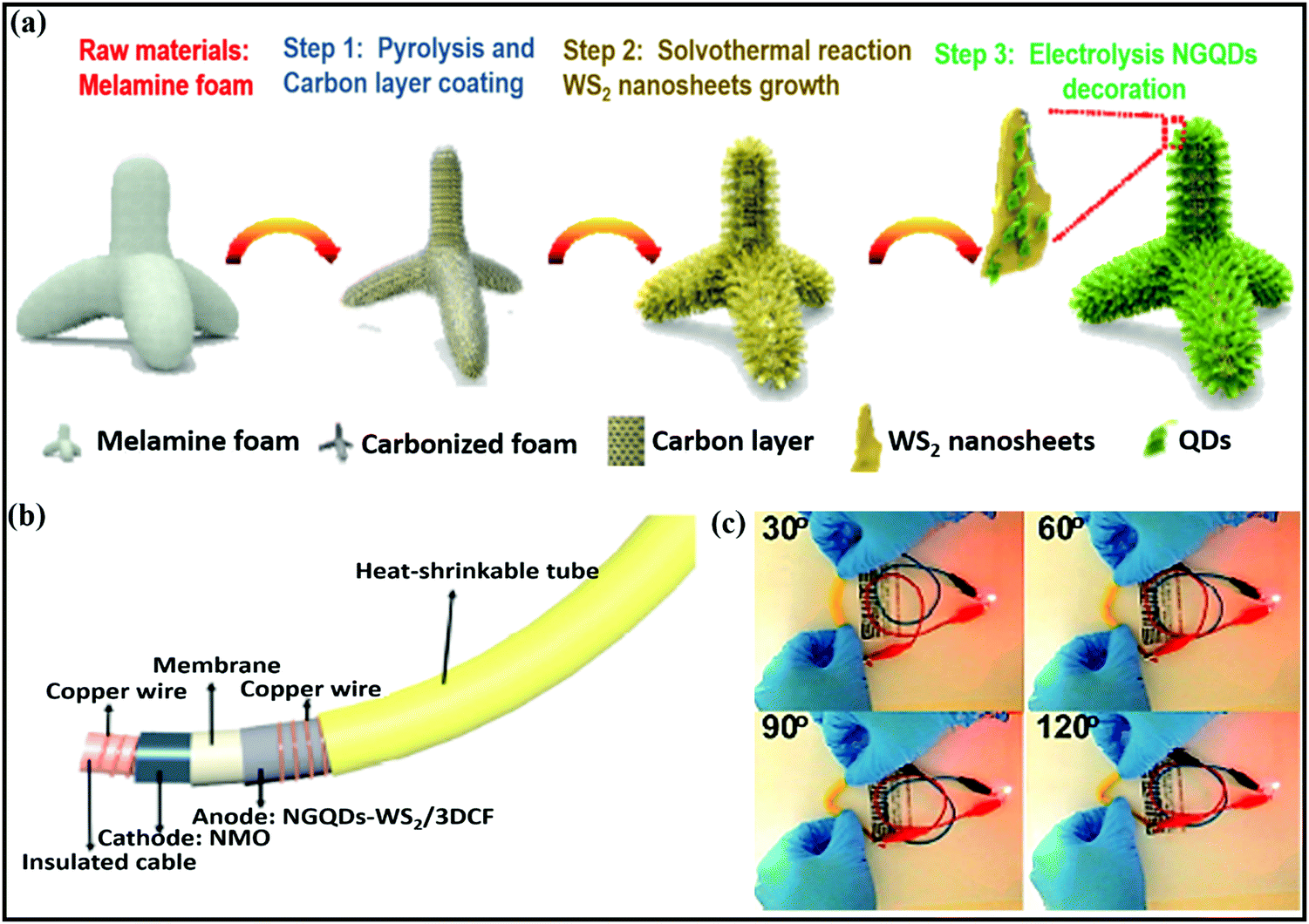 | ||
| Fig. 4 (a) A schematic diagram of the NGQDs-WS2/3DCF nanoarchitecture synthesis process, (b) an image of a flexible cable-shaped SIB with NGQDs-WS2/3DCF as the anode electrode, and (c) photographs of a red LED powered by the cable-shaped SIB at various bending angles. Reproduced with permission.75 Copyright: 2018, Royal Society of Chemistry. | ||
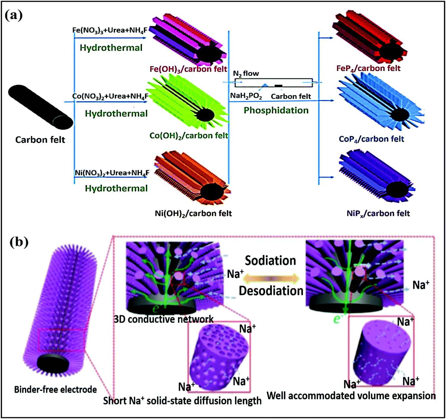 | ||
| Fig. 5 (a) The preparation processes for different metal phosphide arrays on CF and (b) a schematic illustration of (de)sodiation with volume variations and the electron diffusion pathways of the mesoporous CoP4 array. Reproduced with permission.78 Copyright: 2018, Wiley-VCH Verlag GmbH & Co. KGaA. | ||
Distinctive Co9S8 nanorods encapsulated in a N-doped carbon shell (r-Co9S8@NC)79 were mainly designed to prevent large volume changes during cycling, to enhance the storage performance and kinetics, and to prevent side reactions between the electrode and electrolyte. As a composite anode (∼1.1 V vs. Na/Na+), the rationally designed composite reported an initial discharge capacity of 675 mA h g−1 at 50 mA g−1, demonstrating high rate capabilities and good cycling stability via a conversion-based mechanism. In another study, T-Nb2O5 NPs were encapsulated using 1D carbon nanofibers (T-Nb2O5@CNFS),80 where the composite electrode not only provided continuous pathways for electrons to diffuse to electroactive interfaces for reactions with Na+ ion during (de)sodiation but it also acted as a buffer layer to accommodate volume changes during prolonged cycling. Mingkai Liu et al.81 reported a MoS2@carbon nanofiber interpenetrated graphene framework with superior electrochemical performance. In this case, the authors first prepared a carbon-nanofiber-interpenetrated graphene framework and then MoS2 nanoflakes were grown in situ alongside the entire framework. The obtained carbon nanoarchitecture prevents the restacking of graphene sheets and provides ample space between graphene sheets, creating an integrated structure with superior electric conductivity. The anode composite (with an approximate voltage of ∼1.2 V) through an intercalation- and conversion-type mechanism showed a capacity of 598 mA h g−1 at 0.1 A g−1, and 86.9% capacity retention was shown for up to 1000 cycles with high rate performance up to 10 A g−1.
Sheng Chen and co-workers reported red-blood-cell-like hollow carbon sphere supported Na2Ti3O7 (Na2Ti3O7@RHCS)82 with high rate performance. As shown in Fig. 6a, hydrothermal synthesis followed by a calcination strategy is adopted to prepare the Na2Ti3O7@RHCS composite material. Na2Ti3O7 nanosheets are successfully grown on RHCS, offering tailored porosity with short electron-diffusion and ion-channel lengths. In a rate performance study, the composite retained capacities of 175.52 and 45.71 mA h g−1 at rates of 1 and 50C, with a stable average voltage of ∼0.3 V vs. Na/Na+.84 In a distinctive approach, Ming Zhang et al. reported the highly conductive and good sodium-storage performance of graphene-encapsulated FeS2 NPs, which were further modified with CNFs (FeS2@G@CNF) through an electrospinning (Fig. 6b) process.83 The doubly protected anode (∼1.3 V vs. Na/Na+) with a conversion-based mechanism reported a high reversible capacity, good rate performance, and excellent cycling stability (305.5 mA h g−1 was reported after 2400 cycles at 3 A g−1) (Fig. 6c). In addition, the hybrid composite demonstrated excellent electrochemical performance even at low temperatures (0 and −20 °C). Chen et al. constructed a FeS2/CNT neural network composite85 with good cycling stability. The unique composite is endowed with high electronic conductivity and improved electrode kinetics, and volume changes are buffered during long-term cycling. As a result, the FeS2/CNT neural network showed a capacity of 394 mA h g−1 even after 400 cycles at 200 mA g−1 and it demonstrated excellent cycling stability for up to 8400 cycles. Recently, Shuangshuang Tan et al.86 fabricated V2O3 NPs embedded in amorphous CNTs which were then co-assembled with rGO (Fig. 7a) to achieve improved electrochemical performance. Remarkably, the multidimensionally assembled composite anode (∼1.1 V vs. Na/Na+) reported a high rate capacity of 165 mA h g−1 at 20 A g−1 (taking just ∼30 s per GCD cycle), and the composite demonstrated ultra-long cycling stability (retaining 72.3% at 5 A g−1) for over 15000 cycles (Fig. 7b) utilizing a reversible insertion and multiphase conversion mechanism.
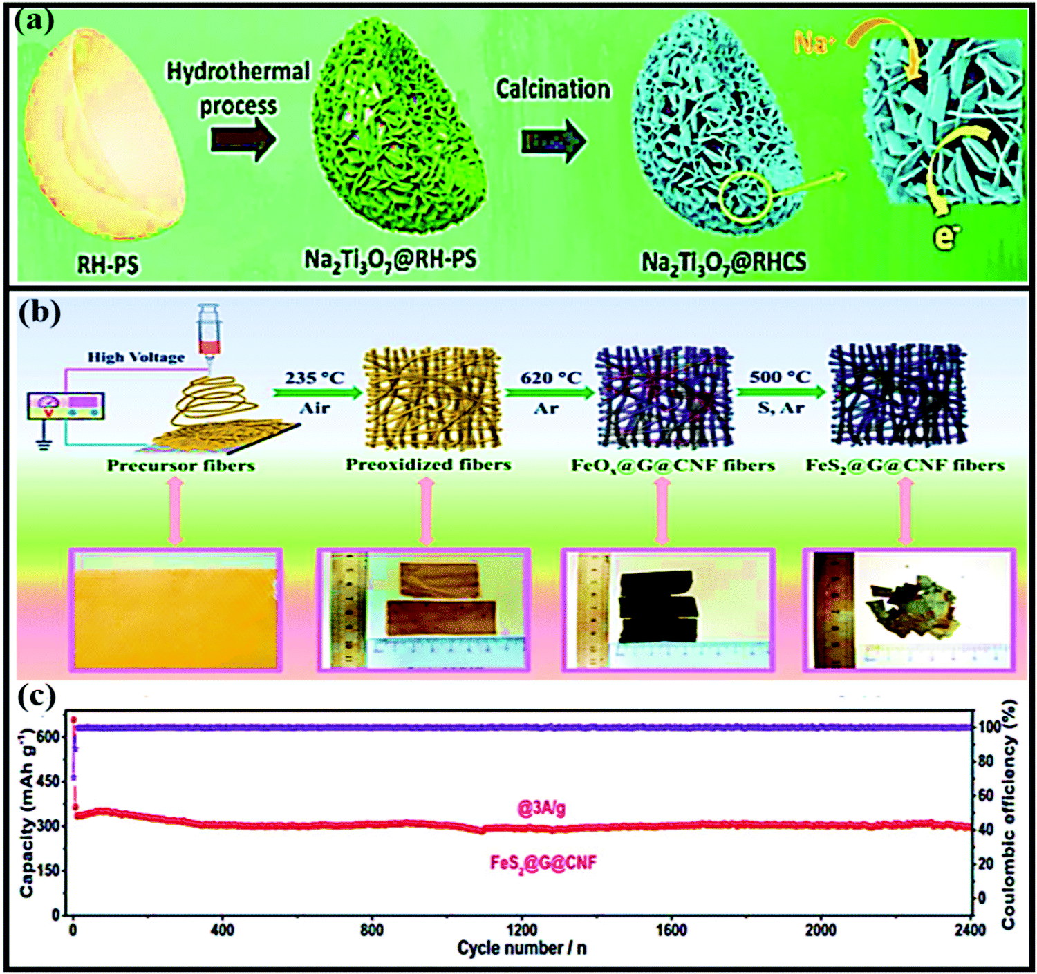 | ||
| Fig. 6 (a) A schematic illustration of the formation of Na2Ti3O7@RHCS. Reproduced with permission.82 Copyright: 2018, Royal Society of Chemistry. (b) Synthetic procedures for the preparation of FeS2@G@CNF and corresponding digital photos. (c) The long-term cycling stability of FeS2@G@CNF at 3 A g−1. Reproduced with permission.83 Copyright: 2019, Wiley-VCH Verlag GmbH & Co. KGaA. | ||
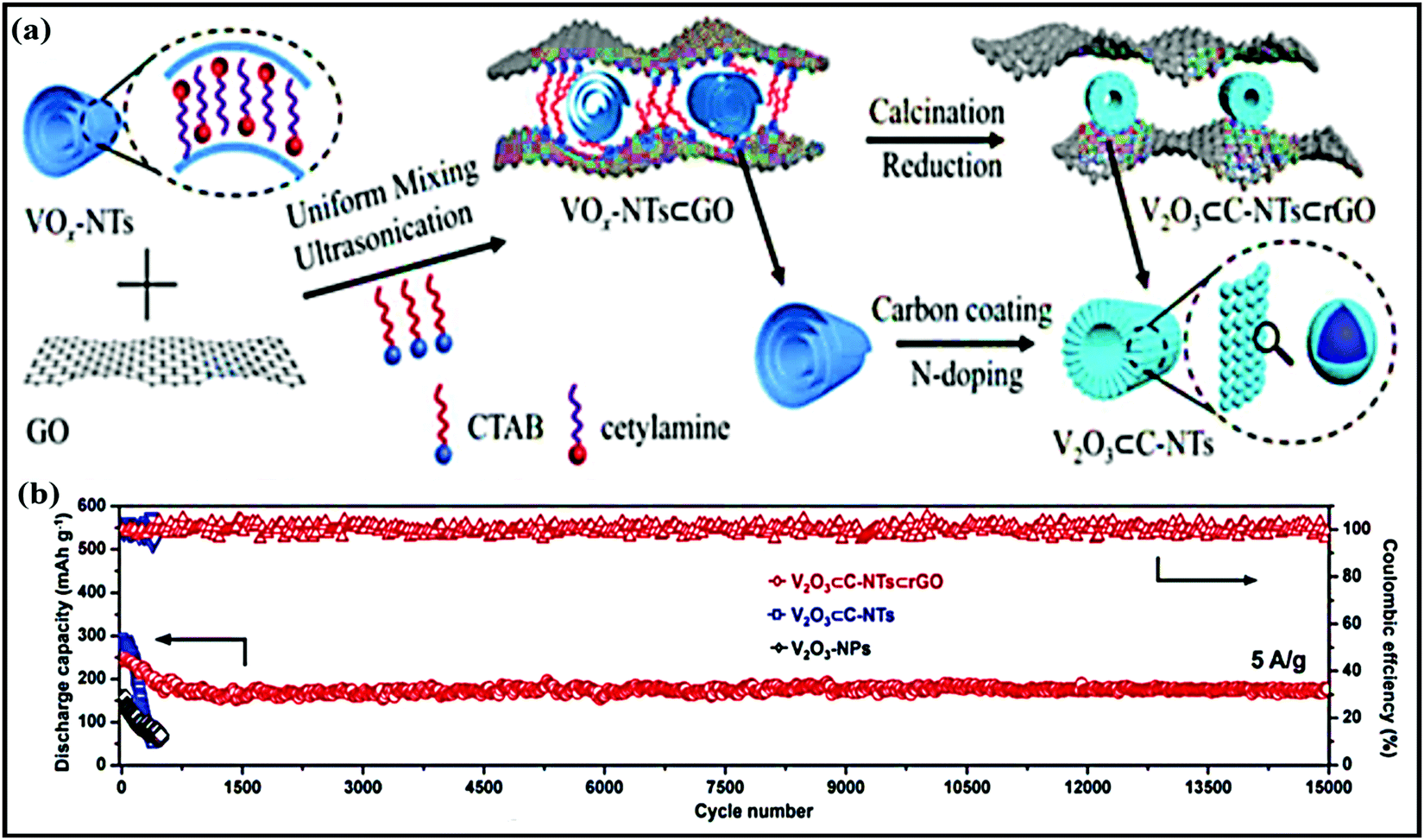 | ||
| Fig. 7 (a) A schematic diagram of the synthesis of V2O3⊂C-NTs⊂rGO and (b) the cycling performances of V2O3⊂C-NTs⊂rGO, V2O3⊂C-NTs, and V2O3-NPs at 5.0 A g−1 (after being initially activated at 0.1 A g−1 for 3 cycles). Reproduced with permission.86 Copyright: 2018, Wiley-VCH Verlag GmbH & Co. KGaA. | ||
Layered metal selenides as energy materials with crystal frameworks with tunable spacing have attracted great attention owing to their abundance and high electrical conductivities and theoretical capacities,87,88 but they suffer from large volume expansion, sluggish kinetics, and dissolution problems.87 Nevertheless, Xing Ou and co-workers reported a promising Sb2Se3@rGO hybrid anode89 (∼0.7 V vs. Na/Na+), which was prepared via a facile one-step solvothermal method. This newly designed composite yields a high reversible capacity even after 500 cycles at 1.0 A g−1 (equal to capacity retention of 90.2%). This recorded reversible (de)sodiation process and marked cycling stability can be attributed to a combination of intercalation and conversion between Na+ and Se and an alloying reaction between Na+ and Sb, respectively.
Co0.8Se@rGO hierarchical nanosheets prepared by Yongxin Huang et al.90 through a simple hydrothermal route registered impressive electrochemical performance with a high reversible capacity of 460 mA h g−1 at 0.5 A g−1 and high rate performance of 448 and 327 mA h g−1 at 0.5 and 4 A g−1, respectively (∼1.2 V vs. Na/Na+). Even at a high current density of 6 A g−1, a considerable specific capacity of 280 mA h g−1 was recorded (achieved with 81% capacity retention). This is mainly attributed to: (i) synergetic effects and the hierarchical porous structure improving the electronic/ionic transport and buffering volume expansion during long-term cycling; (ii) the high conductivity of the rGO layers participating in improvements in the electrochemical performance; and (iii) the novel structural design providing a strong pseudo-capacitive effect with an intercalation- and conversion-based mechanism. Xianfen Wang et al.91 also reported that improved electrochemical performance was shown by a Co9Se8@rGO anode (∼1.2 V vs. Na/Na+) in SIBs. The high performance of this composite is due to the charging process, where Co first reacts with Na2Se to form NaxCoSe2 and then returns to CoSe2 (a conversion reaction) with the help of high conductivity rGO. rGO also played a significant role in controlling the growth and prevents the stacking of Co9Se8 particles, effectively buffering volume changes during charging/discharging and improving the conductance. A NiSe2@carbon composite (∼1.4 V vs. Na/Na+) anode,87 prepared via self-assembly, in situ polymerization, selenization, and carbonization strategies (Fig. 8a), recorded an excellent capacity of 374 mA h g−1 even after 3000 cycles (Fig. 8b) at a current density of 10 A g−1, and it demonstrated ultra-rare performance at various current densities due to strong buffer action (Fig. 8c). Electrochemical kinetics studies demonstrated that the redox reactions were mainly dominated by pseudocapacitive behaviour. A MOSe2@rGO composite anode,92 which is known to be one of the best intercalation hosts, was prepared via a facile hydrothermal method, and it showed improved electrochemical performance, such as high GCD capacities of 556/820 mA h g−1 (while pristine MOSe2 delivers charge/discharge capacities of 353/469 mA h g−1) at 0.5 A g−1. Bare MOSe2 retained a capacity of 220–250 mA h g−1 for 70 cycles and then rapidly decayed. Meanwhile, the MOSe2@rGO composite shows good cycling stability for up to 200 cycles with capacities of 430 and 380 mA h g−1 at 0.5 and 0.1 A g−1, respectively.
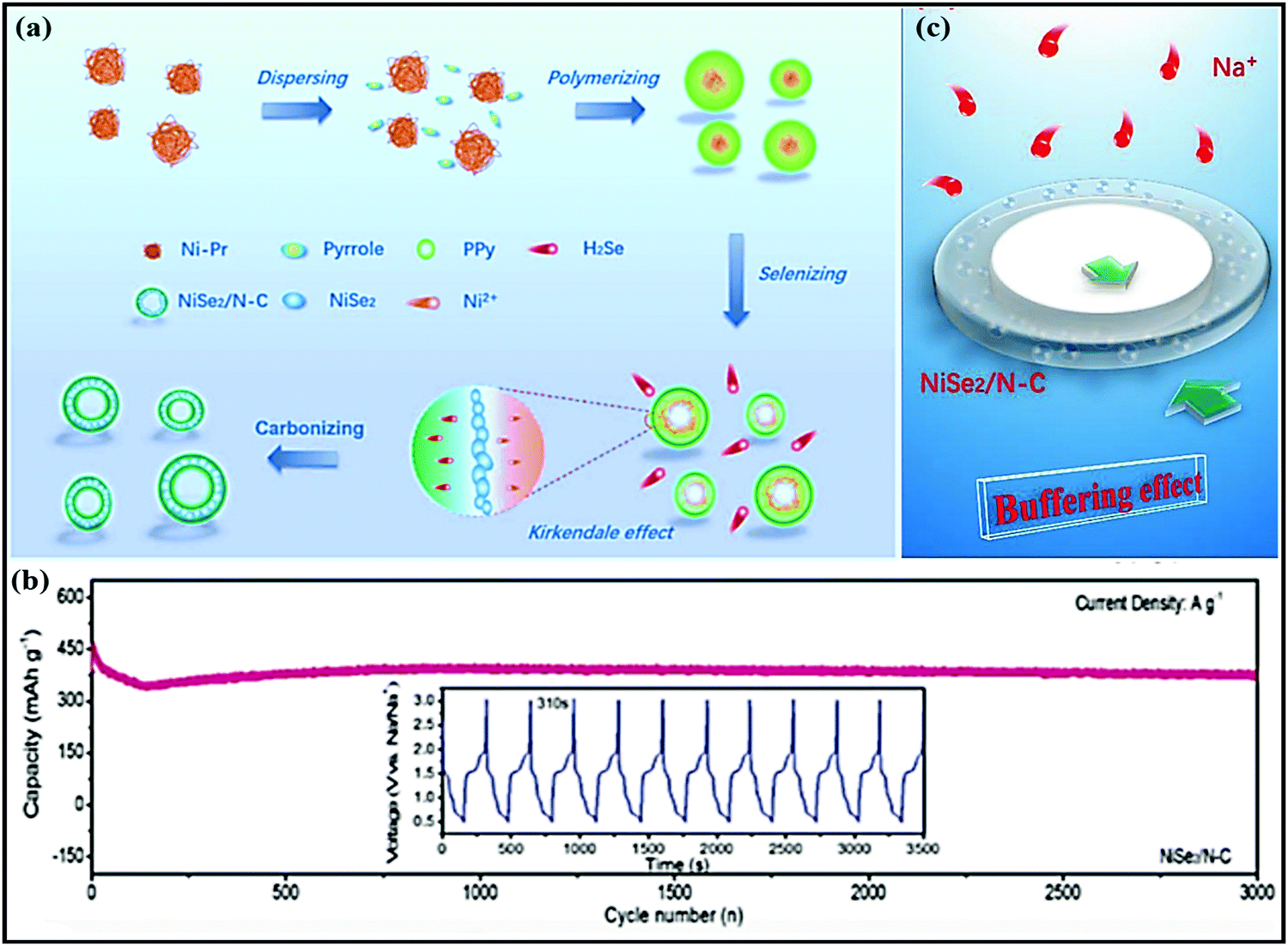 | ||
| Fig. 8 (a) The formation of a hollow-like NiSe2/N–C composite. (b) The long-term cycling stability of the NiSe2/N–C composite and charge/discharge profiles from the 1000th to the 1010th cycle. (c) The mechanism of buffer effect. Reproduced with permission.87 Copyright: 2019, Wiley-VCH Verlag GmbH & Co. KGaA. | ||
Phosphides, analogous to metal selenides, have shown great potential for energy applications owing to their low cost and appealing electrochemical characteristics,93–97 such as high theoretical and volumetric specific capacities. However, poor charge transfer kinetics and alloying reactions accompanied by large volume expansion make them less useful as individual materials.87,94 However, utilizing a suitable host and adopting unique structural design can improve the electrochemical performance via favorable synergetic effects. In one such study, a Sn4P3@rGO composite reported by Qun Li et al.98 demonstrated enhanced electrochemical performance and electronic/ionic conductivity. The alloy-type (∼0.5 V vs. Na/Na+) composite material anode showed a high reversible capacity and, more significantly, the composite demonstrated a capacity of 362 mA h g−1 even after 1500 repeated cycles; this performance was attributed to the abundantly porous nanoarchitecture. Similarly, a phosphorous- and tin-based anode material (Sn4P3–P; Sn:P) with graphene (Sn:P@graphene)99 demonstrated excellent cycling stability (capacities of more than 550 and 371 mA h g−1 at 1 and 2 A g−1, respectively) for over 1000 cycles and high rate performance (capacities of ∼815, 585, and 315 mA h g−1 at 0.1, 2, and 10 A g−1, respectively). This improved cycling stability and rate performance could be ascribed to the novel structural design and stable architecture involving Sn4P3–P and the graphene scaffold. Porous Li4Ti5O12 (PLTO) nanofibers confined in a 3D-interconnected graphene framework (G-PLTO) composite aerogel100 were designed via a hydrothermal process followed by a freeze-drying strategy. The composite was formed due to electrostatic attraction between the positively charged PLTO nanofibers and negatively charged GO. Synergetic effects between PLTO and graphene enabled the composite to demonstrate a high capacity of 195 mA h g−1 at a rate of 0.2C, good rate performance with discharge capacities of 200 and 58 mA h g−1 at rates of 0.2C and 12C, respectively, and remarkable cycling stability (a high capacity of 120 mA h g−1 was retained even after 12000 cycles). In addition, an excellent and highly durable anode (∼1.0 V vs. Na/Na+) is obtained showing intercalation and interfacial Na+ storage between the composite and electrolyte. Liu Wang et al.101 demonstrated a novel scalable approach for preparing a Nb2O5@graphene composite. Electrochemically, Nb2O5@graphene nanosheets, via an insertion-type mechanism (∼0.75 V vs. Na/Na+ storage), reported high rate performance in a range of 0.25 to 20C (a reversible capacity of nearly 100 mA h g−1 was obtained in just 3 min at a rate of 20C, which signifies the excellent rate performance). Bin Luo et al.102 demonstrated controllable conversion from SnO2 to SnS2 on the surface of nanocarbon, depending on the initial SnO2 content. A nanocarbon substrate (rGO or CNTs) with a discontinuous distribution or densely packed distribution of metal oxide nanoparticles (SnO2) could lead to, when sulfurized, the parallel growth of large-area SnS2 film and vertically aligned thicker SnS2 sheets with a smaller contact area with the carbon support. The best interfacial contact can be achieved with ultrathin sheet-like nanostructures, which have parallel alignment with the rGO or CNT phase. However, in either case, the cycling stability is limited due to the large area of insulating SnS2 that is exposed. However, the generation of an amorphous conducting carbon coating before the sulfurization process via the hydrothermal carbonization of glucose was found to stabilize the cell performance, allowing both high rate capabilities and good cycle stability. A layered SnS2@rGO composite103 was fabricated via a facile hydrothermal route, and the main intention was to prevent large volume changes during subsequent cycling and to ultimately boost the electrochemical performance. As expected, the authors achieved enhanced storage performance due to the use of a layered structure with increased interlayer spacing. In addition, rGO improves the electron conductivity and helps to maintain the structural integrity through a synergetic effect. Exfoliated SnS2 (with sizes ranging from 20–50 nm) restacked on graphene104 also showed high performance. The composite was designed through the exfoliation of SnS2via hydrolysis and it was restacked on graphene via a cetyltrimethylammonium bromide-assisted hydrothermal process. The composite showed a capacity as high as 650 mA h g−1 at a current density of 200 mA g−1 with more than 98% Coulombic efficiency. A synergetic effect between the highly conductive graphene scaffold and nanosized SnS2 improved the Na-ion diffusion coefficient and electronic/ionic conductivity. Meanwhile, the graphene network provided more reaction sites and reduced aggregation and volume fluctuations during long-term cycling.
2.2. Phosphate-based composite materials
Phosphate framework materials have undergone a dramatic increase in interest in recent years for use in both LIBs and SIBs owing to some of their intrinsic benefits,22,50,105–108 such as (i) high structural stability due to the very stable P–O crystal framework, which enables long-term cycling stability; (ii) low volumetric expansion and fewer phase transitions; and (iii) high redox potential values and low thermal expansion. However, the intrinsically isolating nature of the phosphate group results in poor electron conductivity and moderate capacities.50 Composite/hybrid formation through rational design is one of the most promising platforms for improving electronic conductivity and electrochemical performance.50,109 For instance, Yang et al. designed 3D NaTi2(PO4)3@rGO microspheres110 as a composite with high-rate and ultra-long cycling abilities. Due to the high surface area, high structural integrity, and conductivity, the NaTi2(PO4)3@rGO anode showed a high discharge/charge capacity and superior cycling performance (77% retention after 1000 cycles at a rate of 20C) with high rate performance (capacities of 130 and 75 mA h g−1 were recorded at 0.1 and 100C, respectively). NaTi2(PO4)3@C111 was prepared via an innovative and facile impregnation method followed by a calcination strategy; it adopted the form of 3D porous architecture and demonstrated favorable electrochemical performance in aqueous electrolyte. In a half-cell (NaTi2(PO4)3@C vs. SCE), the composite recorded capacities of ∼130 mA h g−1 and ∼67 mA h g−1 at 0.5C and 90C, respectively, and the composite reported 89% capacity retention after cycling for up to 2000 cycles with nearly 100% Coulombic efficiency. Recently, Ping Lei et al. fabricated a Na2Ti3/2Mn1/2(PO4)3@carbon112 nanocomposite anode in the form of nanodots, which were uniformly planted in a carbon matrix with an average size of less than 10 nm (∼4 nm). A Na-storage capacity of around 88.6 mA h g−1 was reported at 0.5C, with capacity retention of 90% even after 1000 repeat cycles at a rate of 10C in aqueous electrolyte.A layer-by-layer fabricated NaV3(PO4)3@rGO115 cathode (∼3.3 V vs. Na/Na+) prepared via a self-assembly approach exhibited remarkable electrochemical performance (especially in terms of rate capabilities and cycling stability) due to its high electrochemical stability and electronic and ionic conductivity, leading to excellent cycling stability (70% capacity retention even after 15000 cycles at 50C) and rate performance, even in low- and high-temperature ranges. Xianhong Rui et al.116 designed a 3D hierarchically porous NaV3(PO4)3@C@rGO composite through a convenient freeze-drying assisted strategy. This improved the Na+/electron transport pathways and enhanced the electrode–electrolyte contact area. More significantly, a discharge capacity of 55 mA h g−1 is retained, even after 10000 repeat cycles, which corresponds to 64% capacity retention at an ultrahigh rate of 100C. The highly porous and hierarchical 1D NaV3(PO4)3@C117 nanofiber nanoarchitecture demonstrated fast ion/electron transport capabilities, high structural stability, and high electrochemical performance. Electrospinning followed by a fast-rotating receiver strategy has been applied to fabricate novel NaV3(PO4)3@C nanofiber films. In aqueous electrochemical analysis, especially in a full-cell configuration (Na0.44MnO2vs. NVP@C), the well-designed 1D nanoarchitecture reported a discharge capacity of ∼126 mA h g−1 and demonstrated high-rate and long-term cycling abilities (it retains 84% of the initial capacity after 500 cycles at alternate rates of 5C and 20C with nearly 100% Coulombic efficiency).
Amorphous FePO4 cathodes suffer from low electronic conductivity and low diffusion coefficients.118 The development of FePO4 using graphene not only improved the overall performance of the material but also stabilized the active material through a strong co-operative effect.118 Indeed, the composite registered enhanced rate performance (with capacities of ∼139 and 41 mA h g−1 at rates of 0.1 and 20C, respectively). As claimed by the authors, the improved performance (especially the rate performance) could be attributed to the unique structural architecture, which not only allows the greater penetration of electrolyte and accommodates the strain induced by volume changes during cycling but also provides shorter electron/ion diffusion pathways. In the case of FePO4@rGO,119 the composite provides high-speed pathways for electrons/ions and improves electronic conductivity, and the stable FePO4/electrolyte interface makes sodium ions jump up and down easily, leading to high rate performance and high GCD capacity as a result. Using an FePO4@CNTs composite, capacity retention of about 70, 60, and 55 mA h g−1 was achieved at high current densities of 20, 40, and 60 mA g−1, respectively. Fan et al.113 applied electrospinning followed by heat treatment to obtain NaFePO4 nanodots embedded in porous interlinked N-doped carbon nanofibers (NaFePO4@C) (Fig. 9a). The rationally designed NaFePO4@C composite cathode (∼2.7 V vs. Na/Na+) showed superior cycling stability (89% capacity retention after 6300 cycles) (Fig. 9b) with superior rate performance (a capacity of 61 mA h g−1 at a rate of 5C). Recently, binder-free Na4Fe3(PO4)2(P2O7)@ NaFePO4@core double-shell architectures grown on flexible carbon cloth were designed via a facile sol–gel method followed by a heat treatment strategy114 (Fig. 9c). The carbonaceous parts, such as the carbon cloth and outermost carbon shell, were employed to create a fast 3D electronic conducting network. The porous core–shell electrode could provide ample space to accommodate the strain of volume changes. In battery studies, the composite hybrid cathode (∼3.05 V vs. Na/Na+) reported a discharge capacity of 136 mA h g−1 at a rate of 0.1C, good cycling stability over 3000 cycles at a rate of 10C (Fig. 9d) and good rate performance, even at a rate of 100C, delivering a capacity of 68 mA h g−1 through strong synergetic cooperation.
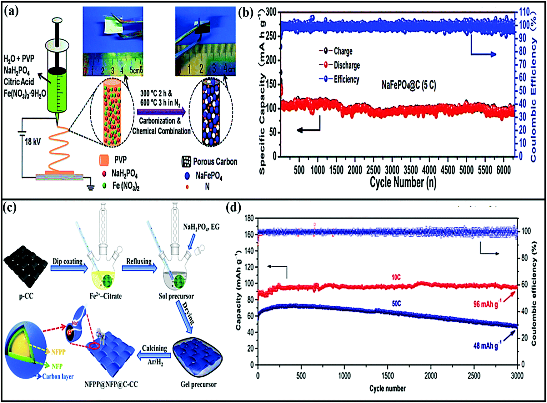 | ||
| Fig. 9 (a) A schematic illustration of the preparation process and (b) the long-term cycling performance at a rate of 5C of NaFePO4@C nanofibers. Reproduced with permission.113 Copyright: 2018, Wiley-VCH Verlag GmbH & Co. KGaA. (c) A schematic illustration of the preparation process of a NFPP@NFP@C-CC flexible electrode and (d) the long-term cycling performance of NFPP@NFP@C-CC at current rates of 10C and 50C for 3000 cycles. Reproduced with permission.114 Copyright: 2019, Elsevier. | ||
2.3. Sulfate-based composite materials
Similar to phosphate-based electrode materials, lately sulfate-based electrodes have gained prominence for use in LIBs and SIBs due to their stronger electronegativity, which is useful for achieving high working potentials.22,120 Although sulfates have shown great potential, they suffer from major drawbacks, like low electronic conductivity, high solubility, and sensitivity to moisture, making them unsuitable materials for SIBs.121,122 However, the rational combination of sulfates with carbon-based networks could be a feasible and promising way to improve the electrochemical performance. Aiming in this direction, Mingzhe Chen and co-workers fabricated a graphene-wrapped Na2Fe2(SO4)3 (NFS@C@GO) composite via adopting a freeze-drying approach.123 The intercalation-type composite cathode recorded a voltage of ∼3.8 V with a discharge capacity of 107.9 mA h g−1 at a rate of 0.1C, and favorable capacity retention of 80.1% even after 800 cycles at 0.6 A g−1. The Non-faradic process contribution (surface contribution) is calculated to be 27.90% at a scan rate of 0.3 mV s−1 with diffusion coefficient values to be of around 10−10.8–10−12 cm2 s−1. A high-performance Na6Fe5(SO4)8 cathode (3.6 V vs. Na/Na+) integrated with 5 wt% CNTs (NFS@CNTs) was designed using a hard carbon (HC) material.124 The composite reported high rate capabilities at different C rates (with specific capacities of 110.2 and 86.4 mA h g−1 at rates of 0.1 and 2C, respectively), with a diffusion coefficient of up to 6.1 × 10⁻¹³ cm2 s−1. Recently, a stretchable Na2+2xFe2−x(SO4)3@graphene (NFS@graphene) composite121 was reported with high conductivity, hydrophobicity, and high electrochemical performance. As a cathode material (∼3.7 V vs. Na/Na+) with an intercalation-type mechanism, NFS@graphene reported an initial discharge capacity of ∼106 mA h g−1 at 25 °C with capacity retention of more than 98% after 700 cycles at 0 °C. Tiantian Yu et al. reported the use of a unique Na2+2xFe2−x(SO4)3@porous carbon-nanofiber hybrid film125 that was obtained using a combination of electrospinning and electrospraying strategies to produce a flexible and self-supported high-performance cathode (∼3.8 V vs. Na/Na+) for SIBs. The composite maintained flexible and rigid architecture after cycling and bending tests.Representative physical properties, capacity values, rate capabilities, and capacity retention data for inorganic materials are summarized in Table 2.
| Composite material | Method used | BET SA (m2 g−1) | Voltage window vs. Na/Na+ (V) | Discharge capacity (mA h g−1) | Rate capabilities (mA h g−1) | Capacity retention | Ref. |
|---|---|---|---|---|---|---|---|
| Phosphorene@graphene hybrid | Liquid-phase exfoliation | — | 0.02–1.5 | 2440 at 50 mA g−1 | 2440 and 645 at 50 mA g−1 and 26 A g−1, respectively | ∼85% after 100 cycles at 50 mA g−1 | 126 |
| Hollow FeSe2/graphitic carbon | One-pot ultrasonic spray pyrolysis | 107.1 | 0.001–3.0 | 898 at 0.2 A g−1 | 540 and 417 at 0.2 and 5.0 A g−1, respectively | ∼88% after 200 cycles at 0.2 A g−1 | 127 |
| MoS2@S-doped graphene | Solvothermal | 79 | 0.005–3.0 | 535 at 100 mA g−1 | ∼535 and 264 at 100 mA g−1 and 5 A g−1, respectively | 80.7% after 1000 cycles at 1 A g−1 | 128 |
| MoS2@PEO | Exfoliation-restacking | — | 0.4–3.0 | 225 at 50 mA g−1 | 185 and 112 at 50 mA g−1 and 1 A g−1, respectively | 65% after 70 cycles from the 5th cycle at 1.0 A g−1 | 129 |
| MoS2@rGO | Hydrothermal | — | 0.01–3 | 702 at 20 mA g−1 | 702 and 352 at 20 and 640 mA g−1, respectively | 49.0% after 100 cycles at 20 mA g−1 | 130 |
| C@MoS2@PPy | Hydrothermal | 38.6 | 0.01–3.0 | ∼665 (2nd cycle) at 0.2 A g−1 | 658 and 417 at 0.1 and 2 A g−1, respectively | — | 131 |
| MoS2-NCS | In situ growth and subsequent pyrolysis | 61.6 | 0.01–3.0 | ∼508.6 (2nd cycle) at 0.1 A g−1 | 508 and 315 at 0.1 and 5 A g−1, respectively | 94.1% after 250 cycles from the 2nd cycle at 1.0 A g−1 | 132 |
| VO-MoS2/N-RGO | — | — | 0.4–3.0 | 254 at 0.2 A g−1 | 254 and 86 at 0.2 and 50 A g−1, respectively | — | 133 |
| MoS2/C-NR | Aerosol-assisted synthesis | 55.1 | 0.001–3 | 637 at 0.5 A g−1 | 439 and 287 at 0.2 and 7.0 A g−1, respectively | 98% after 350 cycles from the 2nd cycle at 0.5 A g−1 | 134 |
| AMCRs@MoS2 | Calcination and hydrothermal | — | 0.01–3.0 | 366 at 1.0 A g−1 | 495 and 302 at 0.05 and 2.0 A g−1, respectively | 87% after 300 cycles at 1.0 A g−1 | 135 |
| MoS2/PDC | A hydrothermal reaction followed by calcination | — | 1.0–3.2 | 475 at 0.2 A g−1 | 372.4 and 301.5 at 0.5 and 5 A g−1, respectively | 90.7% after 340 cycles from the 2nd cycle at 1 A g−1 | 136 |
| SnS2/rGO | Solvothermal | — | 0.005–3 | 469 at 800 mA g−1 | 582 and 501 at 0.2 and 3.2 A g−1, respectively | 61% after 1000 cycles at 1.0 A g−1 | 137 |
| H-MoSe2@NC | — | 291.5 | ∼0.01–3.0 | 561 at 0.2 A g−1 | 475 and 236 at 0.2 and 10.0 A g−1, respectively | 98% after 150 cycles from the 2nd cycle at 1.0 A g−1 | 138 |
| SnO2/GDA | Dual gelation | 124 | 0.01–2.5 | 448 at 0.05 A g−1 | — | ∼58.15% after 200 cycles at 50 mA g−1 | 139 |
| C@P/GA | Vapor-redistribution | — | 0.01–2 | 2085 (2nd cycle) at 0.1C | 2042.5 and 878.6 at 0.2 and 2C, respectively | 66.9% after 200 cycles at 1C | 140 |
| P/CNTs@rGO | Mild solution synthesis | ∼126 | ∼0.01–2 | 2112 at 0.2C | 2112.9 and 286.9 at 0.2 and 6.0C, respectively | — | 141 |
| P@GN | Phase-transformation route | — | ∼0.2–2 | 809 at 1500 mA g−1 | 809 at 1500 mA g−1 | 97% after 350 cycles from the 2nd cycle at 800 mA g−1 | 142 |
| P@rGO | Physical vapor deposition | — | 0–3.0 | 1074.5 at 1593.9 mA g−1 | 1165.4 and 135.3 at 159.4 and 47818.3 mA g−1, respectively | ∼85.06% after 300 cycles from the 2nd cycle at 1593.9 mA g−1 | 143 |
| P/OCNPs | Vaporization–condensation | 26.7 | 0.01–2 | 1644.6 (2nd cycle) at 0.5C | 2398.9 and 1286.7 at 50 and 2000 mA g−1, respectively | 64.3% after 150 cycles at 0.5C | 144 |
| CoP@C/GA | Immersing and phosphorization | 150.8 | 0.01–3.0 | ∼395 (2nd cycle) at 50 mA g−1 | 329.7 and 143 at 50 and 2000 mA g−1, respectively | 115.2% after 4000 cycles at 2000 mA g−1 | 145 |
| Ti3C2 MXene/CNTs | — | 185.4 | 0.01–3.0 | 501 at 20 mA g−1 | — | — | 146 |
| FeS2@NSC | — | 12.64 | 0.01–3.0 | 921.2 at 0.05 A g−1 | 931.2 and 234.9 at 0.05 and 4 A g−1, respectively | — | 147 |
| Sb@rGO@Sb | Electrostatic assembly and reduction | — | 0.005–2 | ∼510 (2nd cycle) at 100 mA g−1 | 480 and 330 at 100 and 5000 mA g−1, respectively | 94% after 200 cycles at 100 mA g−1 | 148 |
| WS2@rGO | Ultrasonic spray pyrolysis | 290 | 0.001–3.0 | 640 at 200 mA g−1 | 404 and 287 at 100 and 900 mA g−1, respectively | 93% after 200 cycles at 200 mA g−1 | 149 |
| CoSex@rGO | Spray pyrolysis | 88 | 0.001–3 | 656 at 0.3 A g−1 | 443 and 357 at 0.2 and 4 A g−1, respectively | 80% after 200 cycles at 0.3 A g−1 | 150 |
| 0D-NTP⊂3D-GN | Hydrothermal process and post-heat treatment | 100 | 1.5–3 | 112 at 0.2 A g−1 | 117 and 85 at 0.5C and 20C, respectively | 80% after 1000 cycles at 10C | 151 |
| Bi/CFC | Hydrothermal | — | 0.01–2 | 737 at 50 mA g−1 | 346 and 240 at 50 and 200 mA g−1, respectively | 93.2% and 74% after 300 cycles at 50 and 200 mA g−1, respectively | 152 |
| pPAN/SeS2 | Electrospinning and simple heat treatment | 88 | 0.8–2.8 | 944 (2nd cycle) at 0.1 A g−1 | 938 and 302 at 0.1 and 5 A g−1, respectively | — | 153 |
| Fe2O3/graphene | Heat treatment | 241.5 | 0.01–2.50 | 561 at 100 mA g−1 | 350 and 194 at 200 and 2000 mA g−1, respectively | — | 154 |
| Sb2S5/graphene | Hydrothermal | 125 | 0.01–3.0 | 845 at 0.1 A g−1 | 525 at 10.0 A g−1 | 91.6% after 300 cycles at 0.2 A g−1 | 34 |
| Bi2S3@graphene aerogel | Hydrothermal reaction followed by freeze-drying | — | ∼0.01–2.8 | ∼585 at 100 mA g−1 | 520 and 336 at 0.1 and 2 A g−1, respectively | ∼66% after 120 cycles at 1 A g−1 | 155 |
| CoTe nanorods/rGO | Hydrothermal | 67.139 | 0.01–2.8 | 459 at 0.05 A g−1 | 459 and 176 at 0.05 and 2 A g−1, respectively | 43.572% after 200 cycles at 0.1 A g−1 | 156 |
| CoSx@NSC | Sol–gel | — | 0.01–3 | 696 at 1 A g−1 | 600 and 526 at 0.2 and 10 A g−1, respectively | 87.5% after 200 cycles at 1 A g−1 | 157 |
| Sb@3D RCN | ESD | — | 0.01–2 | 630 at 0.2C | 564 and 161 at 0.5 and 5C, respectively | ∼70% after 900 cycles at 3C | 158 |
| G@mNb2O5 | Hydrolysis | 366 | 0.01–2.5 | ∼293 at 50 mA g−1 | 293 and 183 at 50 and 500 mA g−1, respectively | — | 159 |
3. Biomass-derived carbonaceous composite materials
In view of environmental concerns, biomass-based energy materials stand out as greener and more sustainable owing to their abundance; other advantages include the manifestation of inherent heteroatoms (N, P, S, Ca, etc.), ease of recycling, tunable surface functionality with high electronic conductivity, the existence of interconnected hierarchical frameworks and open large pore channels (which accelerate the mass transport of ions and electrolytes), etc.160,161 From examining the literature, various biomass-derived carbon sources and strategies adapted to improve the electrochemical performances of SIBs are discussed in this section.A MoSe2/NP-C-2 composite anode162 derived from N,P co-doped bio-carbon obtained using chlorella and MoSe2 was fabricated via a single-step selenization process. The composite electrode in SIBs demonstrated a high reversible capacity of 523 mA h g−1 even after 100 cycles at 100 mA g−1 as a result of a prominent capacitive contribution, and it retained a capacity of 348 mA h g−1 at 2 A g−1 with good cycling stability. Recently Junzhi Li and co-workers reported a novel composite from fungus-derived N-doped CFs with various metal sulfides (MS/NCF; MS = ZnS, Co9S8, FeS, Cu1.81S), and this was subjected to LIB/SIB applications.163 The composites were prepared via a metal-Aspergillus niger bioleaching approach, followed by freeze-drying and a pyrolysis process, to achieve 1D architecture (Fig. 10a). 1D MS/NCF formed with a high surface area, high porosity, and good permeability for Na+ diffusion and transport (Fig. 10b). In particular, the ZnS/NCF composite anode, when used in SIBs, showed a stable capacity of 455 mA h g−1 at 0.1 A g−1, and it retained reversible capacities of 540.2 mA h g−1 at 0.1 A g−1 and 291.5 mA h g−1 at 5 A g−1 (Fig. 10c).
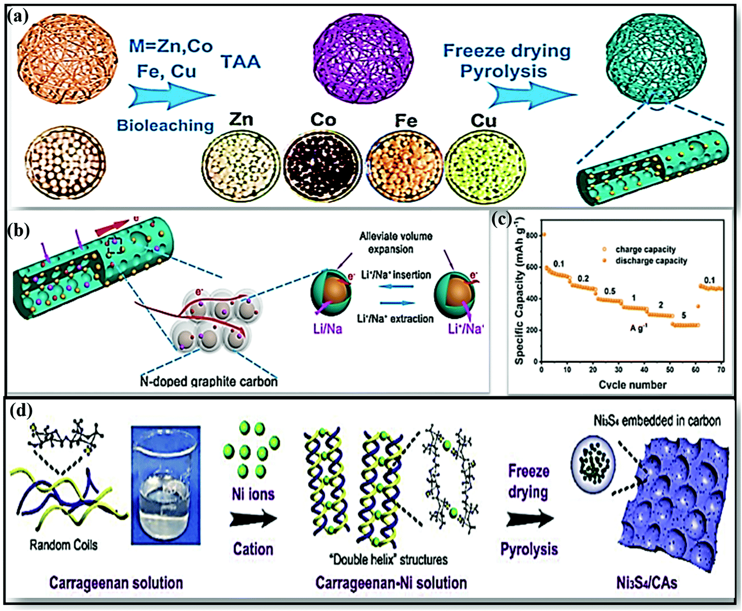 | ||
| Fig. 10 (a) A schematic illustration of the formation of MS/NCF (MS = ZnS, Co9S8, FeS, Cu1.81S). (b) A schematic illustration of the good storage performance of MS/NCF. (c) The rate performance of ZnS/NCF at various current densities. Reproduced with permission.163 Copyright: 2019, American Chemical Society. (d) The synthesis of Ni3S4/CAs. Reproduced with permission.164 Copyright: 2019, Elsevier. | ||
In a more noteworthy fashion, Daohao Li et al.165 used a double-helix carrageenan-metal hydrogel structure for the synthesis of series of hierarchical porous 3D nano-metal-sulfide (MxSy)/carbon aerogel (CA) materials, and these were used in high-performance SIBs. The unique structure improved the Na-ion storage performance through feasible ion/electron transport kinetics and through stabilizing the structure of MxSy. For example, a rationally designed FeS/CA anode (∼1.2 V vs. Na/Na+) composite showed a high reversible capacity with excellent cycling stability (280 mA h g−1 at 0.5 A g−1 for up to 200 cycles). Subsequently, a porous Ni3S4/carbon aerogel (CA)164 composite anode was fabricated with carrageenan and Ni hydrogel as the precursor via a pyrolysis route (Fig. 10d). The electrode, when used in SIBs, showed a stable reversible capacity of 297 mA h g−1 at 1 A g−1 after 100 cycles and good rate performance, with discharge capacities of 424 and 179 mA h g−1 at current densities of 0.2 and 5 A g−1, respectively.
Jiang-ping Tu et al. constructed a new composite from loofah sponge and metal sulfide (LSDCM/MoS2/N–C)166 in the form of ternary sandwich architecture. Due to the novel abundantly porous ternary architecture, the LSDCM/MoS2/N–C composite anode showed improved electrochemical performance, such as a high reversible capacity (∼534 mA h g−1 after 100 cycles at 0.2 A g−1) and good cycling stability (214 mA h g−1 after 300 cycles at 4.0 A g−1). This improved electrochemical performance could be attributed to the 3D sandwich core/shell structure, which prevents aggregation and limits the diffusion of polysulfides into the electrolyte, while the omni-directional conductive network facilitates faster reaction kinetics. Recently, Yuhui Zhang and co-workers167 designed a transition-metal-sulfide hollow NPs@CFs (TMS-HNP@CFs-T, where M = Co, Ni) material from abundant, renewable, and eco-friendly seaweed-derived alginate in the form of CFs. The 1D composite anode material was designed via annealing followed by a sulfuration strategy, as shown in Fig. 11a and b. In this scenario, the CFs effectively improved the electrode/electrolyte surface, resulting in improved electrode kinetics, and the S-doped CFs offer alternative electron transfer paths between the 1D CFs and TMS-HNP.
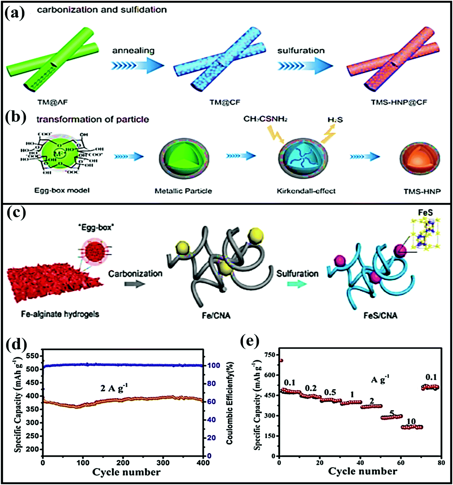 | ||
| Fig. 11 Schematic illustrations of the synthesis of (a) TMS-HNP@CFs and (b) the transformation of TMS-HNP. Reproduced with permission.167 Copyright: 2018, American Chemical Society. (c) A schematic illustration of the synthesis process of FeS/CNA. (d) The cycling performance of FeS/CNA at 2 A g−1 and (e) the rate performance of the FeS/CNA electrode. Reproduced with permission.168 Copyright: 2019, Elsevier. | ||
In another instance, a 1D porous Fe-carrageenan-based material (FeS/CFs)169 was prepared via pyrolysis. FeS NPs are formed in situ via interacting with the sulfur-containing groups of ι-carrageenan, and they are uniformly embedded in the unique 1D porous carbon fibrous matrix. As an anode, the FeS/CFs aerogel showed a high capacity of ∼310 mA h g−1, excellent cycling stability (retaining a capacity of 283 mA h g−1 after 400 cycles at 1 A g−1), and high rate performance (a reported capacity of 247 mA h g−1 even at 5 A g−1). Subsequently, FeS2 NPs anchored on biomass-derived carbon tubes170 also showed a high reversible capacity of 542.2 mA h g−1 at 0.5 A g−1 with reasonable rate performance (it delivers a capacity of 426.2 mA h g−1 even at 2 A g−1) and excellent cycling stability (95.4% retention after 1000 cycles). The outstanding electrochemical performances of all these FeS composite materials are due to the 1D network architectures, which provide paths for ion and electron transport, offer sufficient void space to alleviate volume expansion, improve the electronic conductivity, and enhance the transport kinetics of FeS particles. 3D carbon nanofiber aerogel with well-distributed FeS NPs (CNA)168 was fabricated via a carbonization and sulfuration strategy (Fig. 11c). Electrochemically, the aerogel not only showed a high reversible capacity and good cycling stability (97.4% capacity retention after 400 cycles) but it also showed exceptional high-rate capabilities (with capacities of 473 and 291 mA h g−1 at 0.1 and 5 A g−1, respectively) (Fig. 11d and e).
In a distinctive multi-step approach, Na7V3(P2O7)4@fungus-derived porous carbon171 was designed to form a 3D porous graphene-like carbon framework. Taking advantage of the porous framework, highly conductive skeleton, and good stability, the 3D hybrid achieved higher electrochemical performance via improved electron/ion transport. With a voltage of ∼4.0 V vs. Na/Na+, the composite reported a capacity of ∼90 mA h g−1, and it retains 91% of the initial capacity after 800 cycles.
4. Bimetallic hybrid composite materials
The use of hybrid materials, combining the advantages of individual components, has been considered as an ideal approach for forming unique nanostructures with improved storage performance. Furthermore, the formation of hybrid composites using carbonaceous materials has led to advantages for facile Na-ion storage performance. For instance, a bimetallic SbS@FeS hollow nanorod hybrid embedded into a N-doped carbon matrix172 was fabricated via a facile two-step solvothermal method (first Sb2S3 was obtained via a solvothermal method, then Sb2S3@Fe2O3 was prepared via a hydrothermal process, and this was combined with nitrogen-doped graphene) (Fig. 12a) and used as a high-performance anode (∼1.0 V vs. Na/Na+). The novel designed hybrid structure not only accelerated the electrode kinetics, providing enormous numbers of electrochemically active sites, but it also effectively alleviated volume expansion during cycling via maintaining high structural stability (Fig. 12b). Therefore, the composite reported a capacity as high as 882.2 mA h g−1 at 0.1 A g−1, and high rate performance of 537.9 mA h g−1 even at 10 A g−1, with 85.7% capacity retention even after 1000 cycles at 5 A g−1.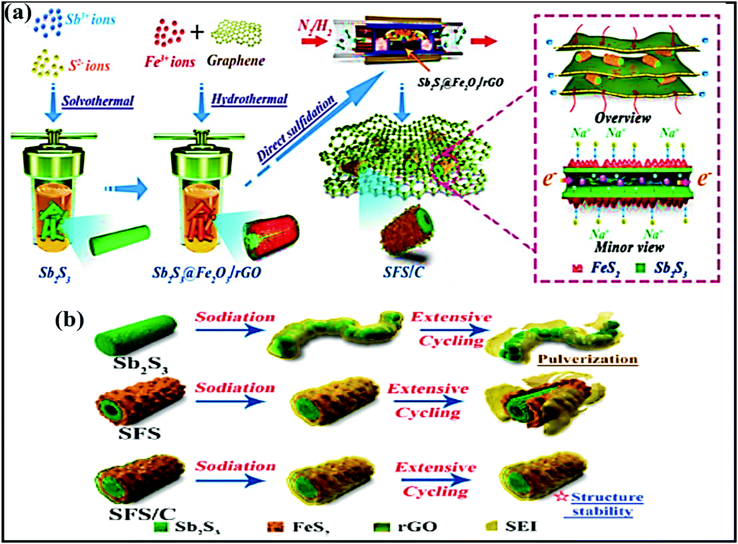 | ||
| Fig. 12 (a) A schematic illustration of the fabrication process of the SFS/C composite and (b) schematic diagrams of the evolution of Sb2S3, SFS, and SFS/C composites upon long-term cycling. Reproduced with permission.172 Copyright: 2020, American Chemical Society. | ||
A heterostructure composed of In2S3–Sb2S3 (I–S) was prepared via a solvothermal process173 and further modified with MCNTs (I–S@MCNTs) to improve the electronic conductivity and sodium storage performance. The resulting anode (∼0.7 V vs. Na/Na+), utilizing an intercalation-, conversion-, and alloy-based mechanism, reported excellent storage performance, with a high reversible capacity of 400 mA h g−1 at 200 mA g−1, high rate performance, and good cycling stability (a capacity of ∼400 mA h g−1 was retained even after 1000 cycles, with capacity retention of 84.2%). Therefore, the promising high electrochemical performance could be due to the formed microspheres, which provide abundant channels for facile diffusion, the dominant pseudocapacitive contribution due to the large surface area, and I–S modification, which lowers the migration barrier via improving the electronic structure of the heterostructure. In addition, MWCNTs maintained the structural integrity, providing effective buffer action and improving the electrode kinetics. Distinctly, 3D SnS–ZnS@C hollow nanoboxes embedded in graphene174 were prepared via incorporating a ZnS–SnS heterostructure. The heterostructured anode showed a capacity as high as 756 mA h g−1 at 0.1 A g−1 and it reported good rate capabilities of 347 mA h g−1, even at a high current density of 1 A g−1. In addition, the anode registered a capacity of 247 mA h g−1 after 1000 cycles at a current density of 2.0 A g−1via a conversion- and alloy-based mechanism.
In a similar fashion, Yongjin Fang et al.175 designed three-layered Cu2S@carbon@MOS2 nanoboxes through a multistep template-engaged strategy (the synthesis process and corresponding FESEM and TEM images are shown in Fig. 13a–c) and used this material as an anode (∼1.25 V vs. Na/Na+). The resultant composite is endowed with improved electrode kinetics and conductivity, and it strongly buffers volume variations during cycling and offers abundant active sites. Electrochemically, the hybrid@composite material, through an intercalation- and conversion-based mechanism, showed a charge capacity of 442 mA h g−1 at 0.05 A g−1 and reported decent rate capabilities of 316 and 297 mA h g−1 even at 2.0 and 3.0 A g−1, respectively (Fig. 13d). NiS2@CoS2 nanocrystals encapsulated in N-doped carbon nanocubes176 were prepared via the polymerization of polydopamine on the surface of NiCoCP and thermally induced sulfurization processes. When used as an anode (∼1.25 V vs. Na/Na+), capacities of 660 and 560 mA h g−1 were reported at 0.1 and 5 A g−1, respectively. This enhanced storage performance could be due to the mesoporous structure and interconnected network. Guozhao Fang et al.177 reported a bimetallic Co9S8/ZnS heterostructure embedded in hollow N-doped carbon nanosheets with excellent reversibility, a high diffusion coefficient, and pseudocapacitive effects. Indeed, when used as an anode (∼0.9 V vs. Na/Na+ with a conversion- and alloy-type mechanism) material, a dominant pseudocapacitive contribution (a surface contribution of 79.9% at 0.2 mV s−1) was reported with a high discharge capacity of 542 mA h g−1 at 0.1 A g−1, and good rate capabilities were demonstrated even at 10 A g−1, with a capacity of 258.6 mA h g−1, and a high diffusion coefficient value.
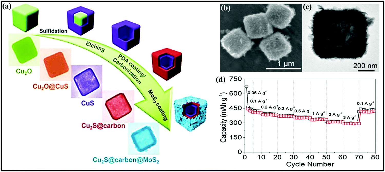 | ||
| Fig. 13 (a) A schematic diagram of the synthetic process of three-layered Cu2S@carbon@MoS2 nanoboxes and corresponding (b) FESEM and (c) TEM images of the three-layered Cu2S@carbon@MoS2 nanoboxes. (d) The rate performance of the Cu2S@carbon@MoS2 nanobox electrode. Reproduced with permission.175 Copyright: 2020, Wiley-VCH Verlag GmbH & Co. KGaA. | ||
Heterostructured Ni2P/ZnP4 embedded in P-doped carbon microspheres178 was reported to show robust structural integrity, abundant active sites, and fast charge-transfer kinetics. Electrochemically, the rationally designed composite (∼0.7 V vs. Na/Na+), through a conversion- and alloy-based mechanism, showed a capacity of 701 mA h g−1 at 100 mA g−1, and it managed decent capacities of 441 and 133 mA h g−1 at 0.1 and 2.0 A g−1 with capacity retention of 66.8% after 500 cycles at 500 mA g−1. Kunjie Zhu et al.179 prepared a MoS2/MoO3/N-doped carbon hybrid anode (∼1.3 V vs. Na/Na+) for the first time. The addition of heteroatoms, such as via N doping, and the unique porous structure increased the electroactive surface area, provided facile diffusion channels due to the 1D architecture, and reduced the transfer distance of ions from/to the electrodes with improved conductivity. In a SIB study, the hybrid retained a capacity of 538.7 mA h g−1 after 200 cycles at 300 mA g−1 and it maintained a capacity of 339.9 mA h g−1 after 220 cycles even at 1000 mA g−1 with nearly 100% capacity retention.
5. Organic composite materials
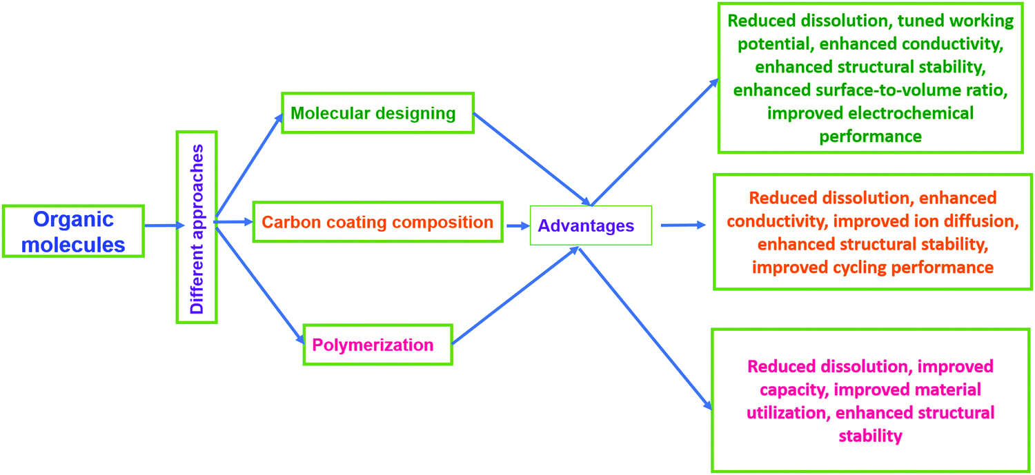
Electroactive organic materials and their derivatives represent promising alternatives to inorganic moieties and have attracted major research interest in recent years180 owing to their many fundamental merits, some of which are as follows: (i) organic electrode materials derived from renewable and abundant resources181,182 do not suffer from issues relating to scarcity or geopolitical conflict issues for resourcing; (ii) they are lightweight and flexible;183 (iii) they are eco-friendly and easily processable;184 (iv) they are cost-effective (being inexpensive, and heavy metals are not involved) and sustainable;4,185,186 (v) there are easy synthesis approaches (typically preparation involves low-cost solution-phase or wet chemistry routes); (vi) they have structural and chemical diversity and tunable properties;187,188 and (vii) there is a minimal environmental footprint.189,190However, on the contrary, electroactive organic materials and their derivatives often exhibit poor rate performance, high self-discharge, rapid capacity loss, and low practical capacities due to low electronic conductivity21,191 and solubility issues in common battery electrolytes.21,192–196 Therefore, several studies and modifications (Fig. 14) have been carried out following different strategies, such as the optimization197 and polymerization of native molecular structures,198–200 rational design/modification with highly conducting materials,180,201–204 and the use of solid-state or gel-state electrolytes.198 Among these strategies, molecular design and/or structural engineering with highly conducting but insoluble carbonaceous materials, such as graphene, GO, rGO, CNTs, CFs, CMK-3, etc., is the most preferred and elegant way to enhance the structural and electrochemical performances in common battery electrolytes. In this section, we will summarize various organic composite/hybrid materials, and methods adopted to enhance the electrochemical performance are highlighted.
 | ||
| Fig. 14 Different approaches for enhancing the properties of organic electrodes. | ||
5.1. Carbonyl-based composite materials
Organic carbonyl moieties are potential high-energy electrode materials due to their high capacities, strong mechanical properties, and fast electrode kinetics.205,206 Moreover, conjugated carbonyl moieties offer numerous chemical options for adjusting the redox properties. However, practical issues, such as low electrical conductivity and high solubility have resulted in low utilization and unsatisfactory electrochemical performance.187,196,205 In an effort to reduce the solubility and stabilize the electrochemical performance, carbonyls containing organic moieties were combined with insoluble carbonaceous materials.207,208 For instance, an effective novel strategy was applied to allow a carbonyl (3,4,9,10-perylene-tetracarboxylic acid-dianhydride; PTCDA) material to be confined on 3D graphene208 through strong π–π interactions (PTCDA particles are dispersed with GO and subjected to a hydrothermal process and, finally, graphene-aerogel-wrapped PTCDA particles (PGC) are obtained after freeze-drying) (Fig. 15a–d). The use of a 3D graphene framework significantly improves the electrical conductivity and Li+/Na+ ion accessibility, shortens the diffusion path length, and, mainly, prevents the dissolution of active material. Benefiting from the above advantages, the composite cathode (∼2.3 V vs. Na/Na+) showed moderate storage capacities (discharge/charge capacities of 81/97 mA h g−1 at a current density of 25 mA g−1) and long-term cycling stability (∼66.9 and 66.4% capacity retention even after 1000 cycles at 50 and 100 mA g−1, respectively), with Coulombic efficiency close to 100%.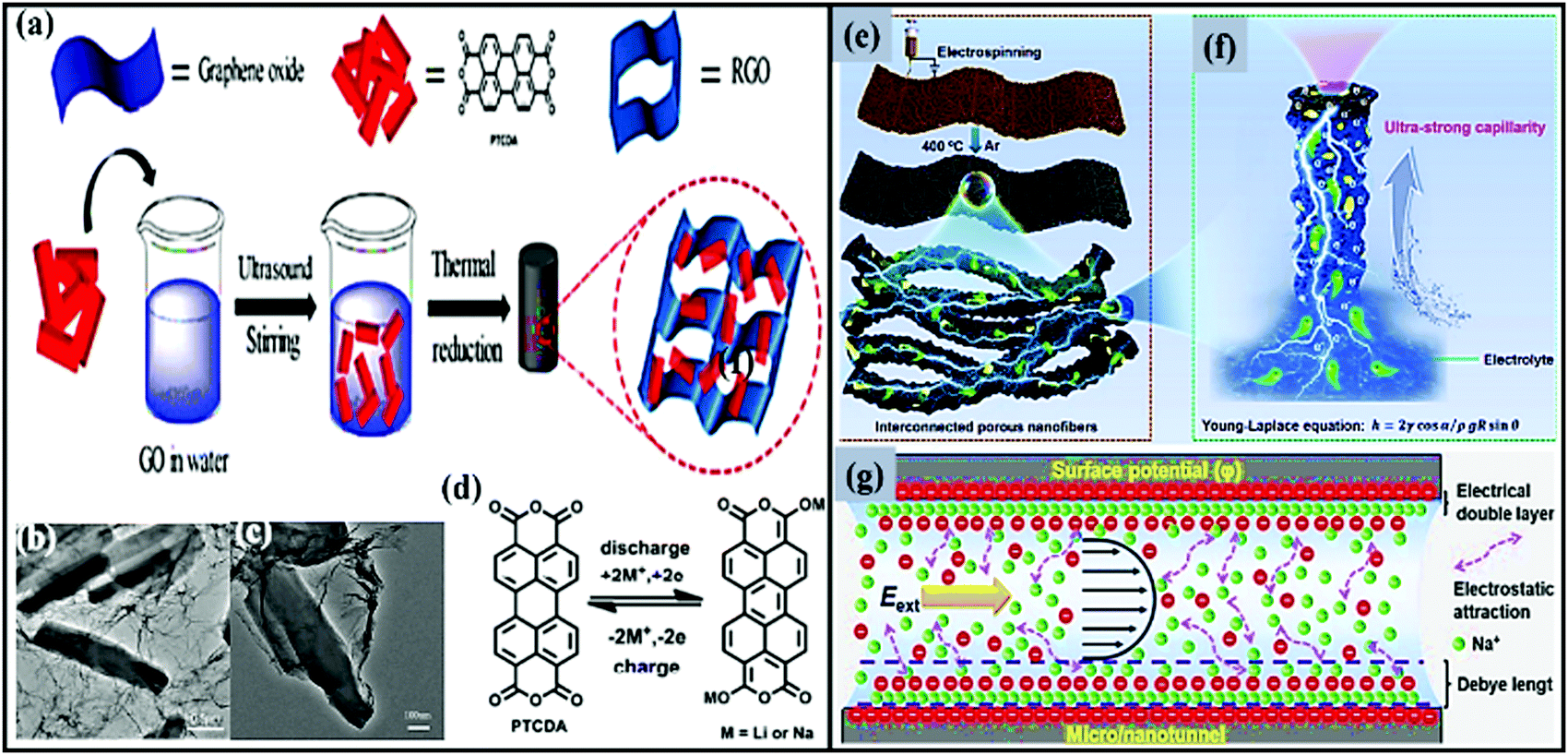 | ||
| Fig. 15 (a) A schematic representation of the fabrication process of PGC. (b and c) TEM images at different magnifications and (d) the redox process of PGC40 during the charge/discharge process. Reproduced with permission.208 Copyright: 2018, American Chemical Society. (e) The preparation of a PTCDA/NC/CNT electrode. (f) A schematic illustration of ultra-fast Na+ transport in a single porous PTCDA/NC/CNT nanofiber assisted by the ultra-strong capillary phenomenon, and (g) a schematic illustration of the ion transport behavior in a negatively charged micro/nanochannel. Eext denotes an external electric field. Reproduced with permission.209 Copyright: 2020, Elsevier. | ||
Considerable progress was achieved via introducing electroactive carbonyl compounds into CNTs. For example, 3,4,9,10-perylenetetracarboxylic dianhydride (PTCDA) was used as an organic carbonyl cathode210 (∼2.25 V vs. Na/Na+) modified with CNTs to overcome solubility issues and improve the storage performance. As expected, the rationally designed flexible and binder-free composite not only provided considerable reversible capacities (150 mA h g−1 at 50 mA g−1 in LIBs and 57.8 mA h g−1 at 25 mA g−1 in SIBs) but it also exhibited good cycling stability (over 500 cycles for LIBs and 300 cycles for SIBs) and good rate capabilities (48 mA h g−1 even at 2000 mA g−1 for LIBs and 48 mA h g−1 at 1000 mA g−1 for SIBs). Herein, CNTs used for composite formation not only act as a current collector but they also improved the electronic conductivity, reduced the solubility, and prevented drastic structural changes during subsequent cycling. Very recently, a PTCDA/N-doped carbon/carbon nanotube (PTCDA/NC/CNT) composite209 nanofiber cathode material, inspired by the microchannels of wood, was designed via electrospinning followed by heat-treatment at 400 °C under an Ar atmosphere (Fig. 15e). The material was designed in such a way that the composite showed fast ionic/electronic transport channels and facilitated fast reaction kinetics (Fig. 15f and g) due to synergetic co-operation between the interconnected conductive framework and ultra-strong capillaries derived from hierarchical micro/nanotunnels. More significantly, the rationally designed composite demonstrated superior structural stability and high in-plane conductivity. The resultant hybrid composite showed good cycling stability for over 500 cycles, with 95% capacity retention at 1 A g−1, and high energy (85 W h kg−1) and power (665 W kg−1) densities; the performance obtained using this hybrid is far superior to other reported SIB systems.
Recently, Aihua Li et al.211 prepared a composite of the sodium salt of poly(2,5-dihydroxy-p-benzoquinonyl sulfide) and rGO (Na2PDHBQS@rGO) to enhance the conductivity and electrochemical performance of Na2PDHBQS. As per their expectations, the Na2PDHBQS cathode performed well in terms of capacity (179 mA h g−1 for the first cycle and 183 mA h g−1 after 150 cycles), cycling performance, and rate performance (showing capacities of 228 and 147 mA h g−1 at 0.1 and 0.4C, respectively, compared to the pure Na2PDHBQS polymer, which showed capacities of 172 and 83 mA h g−1 at 0.1 and 0.4C, respectively) in composite form. The improved electrochemical performance of Na2PDHBQS could be attributed to (i) the insoluble conductive rGO scaffold, which not only enhances the conductivity, but also provides a suitable framework for pore formation; (ii) the formation of a porous structure, which facilitated rapid Na-ion transport and expanded the contact area between the electrode and the electrolyte; and (iii) the effectiveness of polymerization, which improved the electrochemical performance via reducing the solubility. A 4,8-dihydrobenzodithiophene-4,8-dione (BDT) organic cathode also exhibits poor cycling and rate performance due to its high solubility, poor mechanical strength, and low electrical conductivity.212,213 In an effort to reduce the solubility and to improve the cycling stability, Xiaoju and co-workers214 fabricated BDT with a graphene network (BDT-G). Indeed, the novel BDP@graphene composite cathode (∼2.2 V vs. Na/Na+) displayed a high reversible capacity of 217 mA h g−1 and showed better rate capabilities compared to the basic BDT electrode material. Therefore, composite formation with graphene significantly prevented the dissolution of BDT into the electrolyte and intensified the electrode reactions.
In addition to GO, rGO, and CNTs, other insoluble carbon-based materials, such as CMK-3, have also been reported for the fabrication/modification of organic moieties to overcome solubility issue and improve the conductivity. For example, Chunyang Guo and co-workers215 prepared a 9,10-anthraquinone@CMK-3 hybrid cathode composite to improve the electrochemical performance in ether-based electrolyte. At an optimized ratio of 1:1, encapsulated 9,10-anthraquinone demonstrated the highest discharge capacity of 214 mA h g−1 with 88% capacity retention over 50 cycles compared to a capacity of about 178 mA h g−1 with 71% capacity retention after the 50th cycle for an electrode without CMK. The author assumed that dissolution and/or decomposition are the main reasons for the low electrochemical performance of pure 9,10-anthraquinone. Subsequently, Shibing Zheng et al.216 designed a series of calix[4]quinone@ordered mesoporous carbon (CMK-3) composite cathodes (∼2.8 V vs. Na/Na+) to analyze the sodium storage properties. After systematic physical characterization studies, they found that calix[4]quinone was encapsulated inside the pores of CMK-3, and it demonstrated enhanced electrochemical properties due to the stable architecture and synergetic co-operation. This novel calix[4]quinone@CMK-3 composite (especially at a 1:2 ratio) reported an initial discharge capacity as high as 438 mA h g−1 and retained a capacity of 219.2 mA h g−1 after 50 cycles. Further, EIS studies reveal that higher conductivity (reduced cell impedance) and faster ionic mobility (high diffusion coefficient) were achieved in composite form than when using pure calix[4]quinone molecules. However, the authors believed that the CMK-3 nanoporous structure is mainly responsible for the dramatic improvements in the electrochemical performance because it provides high conductivity and fast ionic/electronic mobility and hinders dissolution via strongly encapsulating calix[4]quinone.
A disodium terephthalate@rGO (N2TP@rGO) composite217 hybrid anode (∼0.3 V vs. Na/Na+) was designed to overcome solubility issues and to enhance the Na-ion storage properties. Both hybrid (95% N2TP and 5% GO) and pristine compounds reported capacities in the range of 355–365 mA h g−1 at 0.1C, but improved cycling stability and rate performance were observed for the N2TP@rGOcomposite. Similar to many works in the literature, the GO used here for making the composite not only stabilized the structure of N2TP but it also improved the electrical conductivity after being electrochemically reduced. A 2,5-disodium-1,4-benzoquinone (Na2DBQ) organic anode (∼1.2 V vs. Na/Na+) was immobilized on ordered mesoporous carbon (OMC) through strong π–π supporting interactions. The intimate contact between Na2DBQ and the conductive carbon improved the specific surface area and electrochemical performance218 in an ionic-liquid-assisted electrolyte media. Liqiao Zhong et al. fabricated high-performance aqueous rechargeable SIBs using alloxazine@CMK-3219 as an anode and polyacrylamide hydrogel as an electrolyte. Alloxazine encapsulated in CMK-3 demonstrated a two-electron transfer reaction, with an initial discharge capacity of 160 mA h g−1, and the composite in full-cell configuration exhibited an energy density of 50 W h kg−1 (corresponding to 146 mA h g−1). Hua Wang et al.220 presented a novel biomolecule “juglone” derived from waste walnut epicarp and immobilized onto rGO nanosheets through π–π interactions. This ordered fabricated juglone recrystallized and assembled into microrods on the rGO layer, and it was directly used as an anode material (∼0.8 V vs. Na/Na+) without using a binder. In electrochemical studies, the pristine juglone molecules immobilized onto rGO nanosheets are less soluble in the electrolyte and they exhibited impressive electrochemical performance, such as high electronic/ionic conductivity and good reversibility, with a high discharge capacity of 305 mA h g−1, which is higher than the capacity of pure juglone molecules (40 mA h g−1) and the rGO network charge/discharge capacities (110/123 mA h g−1). Stable capacity retention (a capacity of ∼212 mA h g−1 is maintained after cycling up to 300 times) and high rate performance (capacities of ∼398 and 210 mA h g−1 are achieved at current densities of 0.05 and 0.4 A g−1, respectively) are also seen. It is believed that the great mechanical strength and high conductivity of rGO are the main reasons for the excellent electrochemical performance of the juglone molecules.
5.2. Carboxylate-based composite materials
Conjugated carboxylate moieties are considered as candidate materials with high capacities221 and high thermal stabilities222 for RLIB and SIB applications. However, the use of polymerizable molecular structures and easy-to-fabricate conductive materials is highly desirable to reduce solubility issues, stabilize structures, and improve electrochemical performances. For instance, a graphene-wrapped sodium naphthalene dicarboxylate (Na4C8H2O6)223 composited anode (∼0.4 V vs. Na/Na+) demonstrated a high reversible capacity of 226 mA h g−1, exceptional cycling stability (92% capacity retention over 100 cycles), and high rate capabilities. Meanwhile, the specific capacity of Na4C8H2O6 nanoflowers is limited to 179.5 mA h g−1 at 164.7 mA g−1 with 89% capacity retention over 100 cycles. Chao Luo et al.224 introduced a new croconic acid disodium salt (CADS) as an anode for SIB applications. CADS exhibited a high reversible capacity, but it suffers from fast capacity decay during subsequent GCD cycles. After a detailed investigation, the authors reveal that the loss of electrode performance is mainly attributed to large volume changes (phase transformation) rather than the dissolution of CADS into the electrolyte. Therefore, to overcome severe capacity loss, CADS particles were wrapped in GO to enhance the reversible specific capacity and stability. The resultant composite, benefiting from a synergetic effect between the GO scaffold and CADS NPs, shows a higher discharge capacity of 293 mA h g−1 (after subtracting the GO capacity contribution) at 20 mA g−1, with better cycling life compared to the performance of a basic CADS electrode. Subsequently, sodium humate (Na2HA), with non-conjugated carboxylate groups, coupled with rGO225 (Na2HA was mixed with a GO suspension via ultrasonic irradiation, and then the mixture was dried and thermally treated at 200 °C for 2 h under an Ar/H2 atmosphere) (Fig. 16a) was reported as an anode (∼0.6 V vs. Na/Na+) material with a reversible capacity of ∼133 mA h g−1 at a current density of 500 mA g−1. More significantly, the composite, especially with 6% rGO, was exceptionally stable, with a capacity retention of 91.6% even after 2000 repeated GCD cycles (Fig. 16b–d).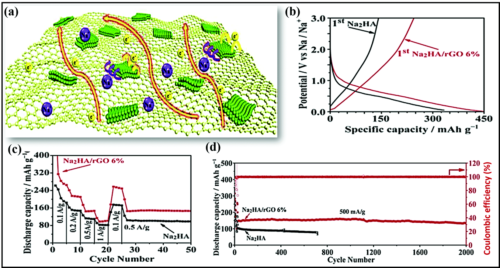 | ||
| Fig. 16 (a) A schematic illustration of charge transfer in a hybrid Na2HA@rGO electrode. (b) The initial charge–discharge curves from 0.01 to 3.0 V at a current density of 100 mA g−1, (c) the rate capabilities, and (d) the cycling stabilities of bare Na2HA and the Na2HA@rGO (6%) composite material at 500 mA g−1. Reproduced with permission.225 Copyright: 2018, Elsevier. | ||
5.3. Hydroxyl-based composite materials
Tianyuan Liu et al.226 reported a dopamine@rGO framework cathode, which was obtained via coating dopamine onto a 3D graphene framework. In this case, GO plays an important role as an oxidant and acts as a strong protective barrier and high surface area template to enhance polydopamine surface redox reactions. The resulting hybrid cathode (∼2.8 V vs. Na/Na+) showed high reversible capacities of 230 and 211 mA h g−1 in LIBs and SIBs, respectively, at 0.05 A g−1, and 1000 cycles could be carried out with more than 95% Coulombic efficiency. The impact of composite formation is further exemplified by polydopamine@few-walled CNT (FWCNT)227 composite cathode (∼3.2 V vs. Na/Na+) formation. Similar to the polydopamine@rGO framework,226 the polydopamine@FWCNTs composite demonstrated an improved gravimetric capacity of 133 mA h g−1 in a Li-ion cell and 109 mA h g−1 in a Na-ion cell. In subsequent cycles, the specific charge/discharge capacities (polydopamine@FWCNTs vs. Li/Li+) remained constant in a reversible manner with high cycling stability for over 10000 cycles. Moreover, the high-rate performance was also maintained via utilizing double-layer capacitance from the FWCNTs and multiple redox reactions involving polydopamine.
5.4. Polymer-based composite materials
A novel graphene@polyimide (GF-PI) hybrid composite228 was prepared via a one-step solvothermal process and used as a binder-free cathode (∼2.2 V vs. Na/Na+) material for LIB and SIB applications. Compared with polyimide, the graphene@polyimide composite showed an enhanced specific capacity and good cycling life. Here, the polyamide (PI) polymer is mainly responsible for the high stability and fast Li- and Na-ion diffusion properties. Similar beneficial effects were observed for a rationally designed PI@MWCNTs nanocomposite (Fig. 17a) material.229 The nanocomposite was prepared via two-step polycondensation. In the first step, the polycondensation of PTCDA and diaminopropane in NMP in the presence of MWCNTs leads to the formation of PAA/MWCNT and in the second step, the PI/MWCNTs nanocomposite is formed via the imidization of polyamic acid during stepwise thermal treatment up to 400 °C. The combination of MWCNTs with a gel-polymer electrolyte was used to stabilize the native PI and to improve the electrochemical performance. The resultant composite cathode (∼2.1 V vs. Na/Na+) material in gel-polymer electrolyte reported good cycling life for up to 3000 cycles and good rate performance (Fig. 17b and c) at rates up to 10C, despite a low specific capacity (the initial discharge capacity is 98 mA h g−1 and this will reach 100 mA h g−1 after a few cycles), compared to a novel graphene@polyimide (G@PI) hybrid composite material.228 However, the interconnected 3D network of the MWCNTs enhanced the electrode conductivity and improved the utilization of active material. A gel-polymer-electrolyte-based polyacrylonitrile nanofibrous membrane was also used to enhance the electrode kinetics.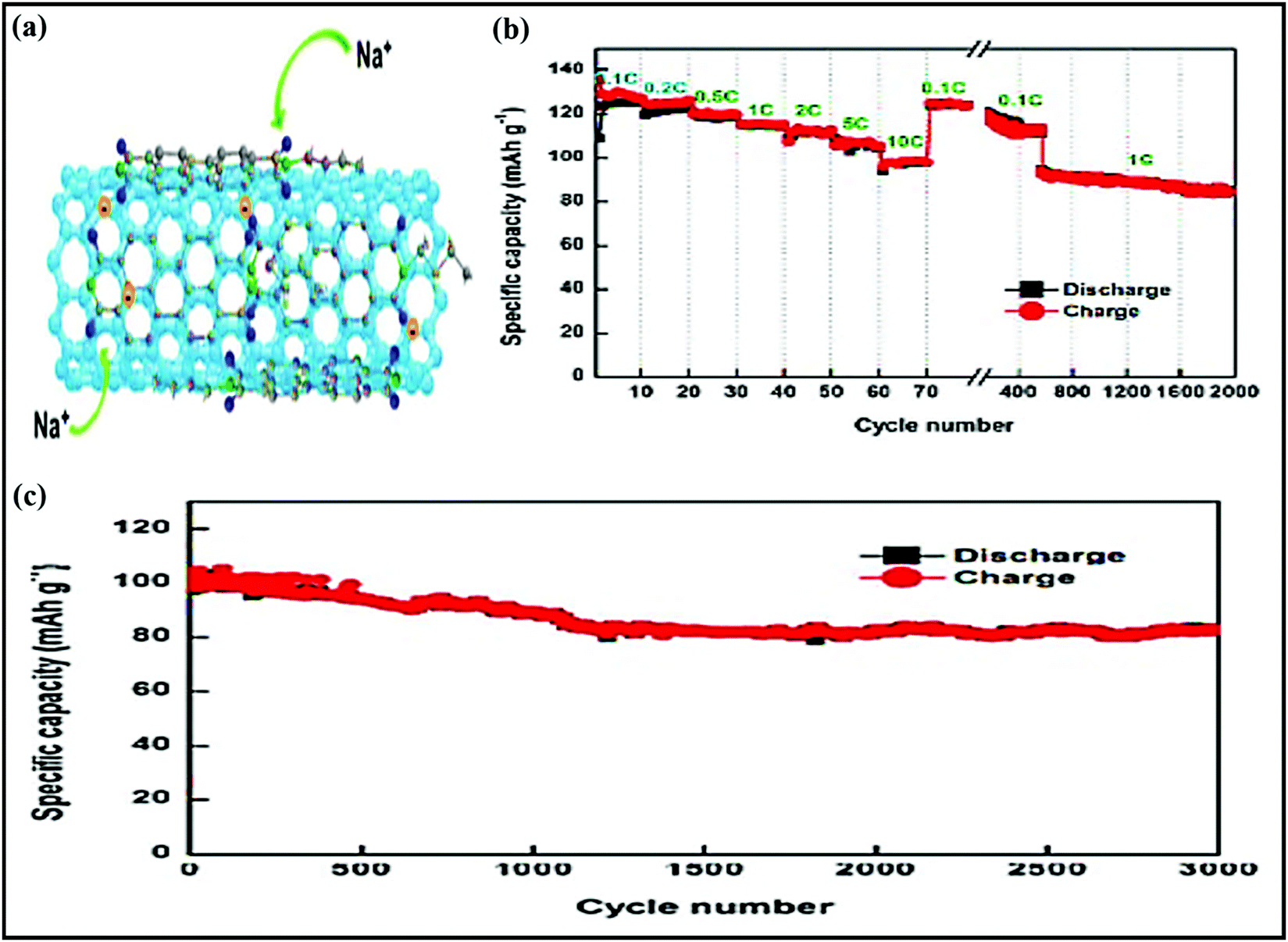 | ||
| Fig. 17 (a) The PI/MWCNT nanocomposite cathode. (b) The cycling performance at different C-rates and (c) the cycling performance at a rate of 5C of the PI/MWCNT nanocomposite cathode. Reproduced with permission.229 Copyright: 2018, American Chemical Society. | ||
Abundant, low-cost, and eco-friendly nitroxide radical polymers (NRPs) have been reported as high-voltage (∼3.47 V vs. Na/Na+) cathode materials,230 but they suffer from low electrochemical performance; nevertheless, they demonstrated high electrochemical performance in composite/hybrid form. For example, pyrene-functionalized NRPs were anchored on highly conductive CNTs through π–π interactions.230 Such pyrene-functionalized NRPs homogenously and non-covalently attached (like molecular glue) to CNTs forming a stable architecture. Detailed electrochemical studies revealed that the rationally designed composite not only demonstrated a high reversible capacity (107 mA h g−1 at a rate of 1C) but it also showed superior cycling stability (92% capacity was retained even after up to 6000 cycles at a current density of 2.2 A g−1) with good rate capabilities (78 mA h g−1 at 5.5 A g−1).
Similarly, the poly(2,2,6,6-tetramethyl piperidinyloxy-4-vinylmethacrylate) (PTMA) polymer was reported to be a promising cathode material for SIB applications, but its high self-discharging tendencies due to solubility issues raise questions relating to future rechargeable battery applications.192,231 However, to address the solubility issues and enhance the storage performance, Jae-Kwang Kim and co-workers synthesized a PTMA@CNTs hybrid composite material.193 The novel PTMA-impregnated CNT composite cathode (∼3.4 V vs. Na/Na+) exhibited high thermal stability, a large surface area (122.1 m2 g−1), high conductivity, fast electron transport properties, and enhanced electrochemical performance, with a high reversible capacity, better capacity retention, and higher rate capabilities. The used highly conductive CNTs not only alleviated the dissolution and self-discharge issues relating to PTMA but they also provided effective conducting paths and enabled rapid electron transport throughout the PTMA polymer.
A poly(2,5-dimercapto-1,3,4-thiadiazole) (PDMcT)@nitrogen and sulfur co-doped graphene nanosheets232 material was prepared via the polymerization of PDMcT on the surface of GO and subsequent calcination (Fig. 18a–c). The proposed PDMcT@rGO anode (∼1.2 V vs. Na/Na+) (Fig. 18d–h) showed a high discharge capacity of 240 mA h g−1 at 500 mA g−1 and exhibited superior cycling stability, with a capacity of 153 mA h g−1 even after 5000 cycles at 5000 mA g−1, and high rate performance (144 mA h g−1 even at 10 A g−1). Kinetics studies suggest that the surface contribution (a capacitive contribution of 85% was obtained at 2.0 mV s−1) is more dominant in this electrochemical process.
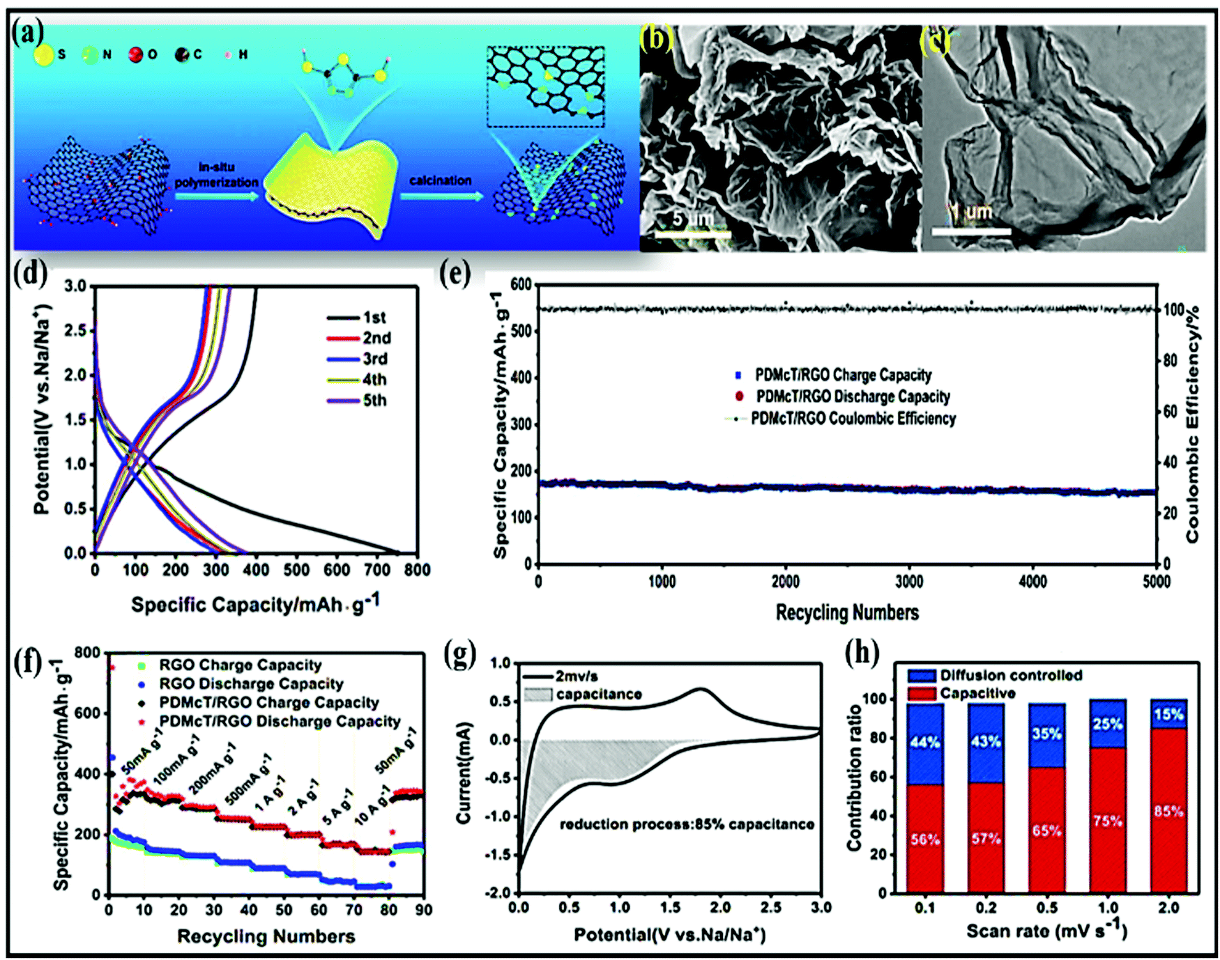 | ||
| Fig. 18 (a) The preparation process and (b and c) SEM and TEM images of PDMcT@rGO. (d) Charge/discharge profiles of PDMcT@rGO at 50 mA g−1, (e) the cycling stability of PDMcT@rGO at 5000 mA g−1, and (f) rate capability profiles of PDMcT@rGO and rGO at various current densities. (g) The separation of the capacitive and diffusion currents during the reduction process at a scan rate of 2.0 mV s−1 and (h) the capacitive contribution ratios of the PDMcT@rGO composite at different scan rates. Reproduced with permission.232 Copyright: 2018, American Chemical Society. | ||
Representative physical properties, capacity values, rate capabilities, and cycling performance data for organic composite materials are summarized in Table 3.
| Composite material | Method used | BET SA (m2 g−1) | Voltage window (V) | Discharge capacity (mA h g−1) | Rate capabilities (mA h g−1) | Cycling stability | Ref. |
|---|---|---|---|---|---|---|---|
| Potassium terephthalate@graphene | Wet chemistry | 0.01–2 | 210 at 0.1C | 192 and 95 at 0.1 and 2C, respectively | ∼91% after 200 cycles at 1C | 233 | |
| Pillar[5]quinone@CMK-3@SWCNTs | — | 1330 | 1.5–4.2 | 418 at 0.1C | ≈425 and 201 at 0.1 and 1C, respectively | ∼69% after 300 cycles at 0.1C | 234 |
| Pyromellitic dianhydride-4,4′-diaminodiphenyl etherpolyimide@CNTs | Electrospinning and step-by-step heat treatment | — | 1.2–3.5 | 123 at 0.1C | ∼123 and 56 at 0.1 and 1C, respectively | ∼93% after 200 cycles at 0.5C | 235 |
| PYT-TABQ@rGO | Direct polycondensation | 97.7 | 1.0–3.5 | ∼245 at 0.2 A g−1 | ∼254 and 210 at 0.2 and 1.0 A g−1, respectively | 98% after 1400 cycles at 0.5C | 236 |
| PDBM@graphene | — | — | 2.0–4.0 | 210 at 30 mA g−1 | ∼200 and 125 at 60 and 480 A g−1, respectively | ∼57% after 100 cycles at 30 mA g−1 | 237 |
| C4Q/CMK-3/SWCNTs | — | — | 1.2–4.2 | ∼440 at 0.1C | 439 and 346 at 0.1 and 1C, respectively | ∼65% after 100 cycles at 0.1C | 238 |
| DHTPA@CB | — | — | 0.01–2.0 | ∼100 at 25 mA g−1 | ∼95 and 73 at 25 and 1500 mA g−1, respectively | ∼90% after 100 cycles at 25 mA g−1 | 239 |
| Polyacrylonitrile/humic acid | Electrospinning and carbonization | 27.57 | 0.01–2.7 | 261.3 at 0.02 A g−1 | 208.6 and 81.7 at 0.2 and 1 A g−1, respectively | 92.8% after 100 cycles at 0.1 A g−1 | 240 |
| Na2TP@GE | Freeze-drying and sintering | — | 0.01–2 | 268.9 at 0.1 A g−1 | 141 at 0.6 A g−1 | 207.9 mA h g−1 after 500 cycles at 0.1 A g−1 (77.3% capacity retention) | 241 |
| PDIDA/CBs | In situ condensation | — | 1.50–3.50 | 90 at 2 A g−1 | — | No capacity loss after 1000 cycles at 1.0 A g−1 | 242 |
| Na2C6O6-PANI | Antisolvent precipitation | — | 0.5–3.2 | — | 220 at 500 mA g−1 | 174 mA h g−1 after 50 cycles (63% capacity retention) | 243 |
| PDI/RGO | Solvothermal and thermal treatment | 211.4 | 1.5–4.3 | — | 122 and 73 at 100 and 800 mA g−1 | ∼175 mA h g−1 after 500 cycles at 50 mA g−1 | 244 |
6. Organic–inorganic hybrid/composite materials
Inorganic–organic hybrid electrode materials used in SIBs mostly include metal–organic framework and polymeric nanocomposites.6.1. MOF-derived composites
The new fascinating class of periodic framework porous materials known as metal–organic frameworks (MOFs), prepared via the combination of various inorganic metals and organic ligands47,245,246 through coordination bonds, has shown great potential for energy (LIB) applications. Similarly, the application of MOFs in SIBs46,47,247 has been intensively investigating owing to their structural diversity, high surface areas, hierarchical nanostructures, high porosity, controllable functionality, good redox properties, and simple synthesis strategies.248,249Although MOFs have many attractive properties that are suitable for SIBs, most MOF parent/precursor materials are limited by inherent limitations, such as poor electrical conductivity and stability issues (limited cycle lives),47,245,249,250 which are detrimental to obtaining high reversible capacities, good rate capabilities, and long-term cyclability. However, MOF-derived materials, especially rationally designed MOF-derived materials such as composites and/or hybrids, encapsulated materials, substrate-supported materials, etc., are expected to exhibit remarkable electrochemical performances via improvements in electronic/ionic conductivity, electrochemical stability, insolubility, and flexibility through favorable synergetic effects.245,250
Furthermore, the desired composition and structural architecture (Fig. 19) can be obtained through tuning either the internal or external structure or a combination of both via a suitable synthetic pathway.251 For instance, Xijun et al.252 prepared advanced carbon-encapsulated metal selenides through calcination followed by a selenidation strategy (Fig. 20a). Rationally designed selenides, such as Cu2Se@C, Fe7Se8@C, and NiSe@C, can be used to generate anodes with particular nanostructured and microstructured architectures, demonstrating long-term cycling stability and superior rate performance (Fig. 20b and c). In particular, a MOF-derived Fe7Se8@C nanorod anode (∼1.25 V vs. Na/Na+) retained a specific capacity of 218 mA h g−1 after 500 cycles, while NiSe@C spheres with an intercalation-based mechanism reported a capacity of 160 mA h g−1, even after cycling for up to 2000 cycles at 3 A g−1, with high rate performance. A Co3O4@N-doped carbon composite anode (∼0.8 V vs. Na/Na+)253 derived from the MOF ZIF67 was fabricated to achieve a high storage capacity and to improve the cycling stability. As expected, the rationally designed Co3O4@N-doped carbon composite, through a conversion-based mechanism, reported GCD capacities (516/813 mA h g−1 at 0.1 A g−1) that are much higher than those of pure Co3O4 (326/495 mA h g−1 at 0.1 A g−1), and the rate performance results in capacities of 506 and 263 mA h g−1 at current densities of 100 and 1000 mA g−1, respectively. More importantly, capacity degradation of a mere 0.03% per cycle over 1100 cycles was seen, depicting the robust integrated composite framework. In this scenario, the nitrogen-doped carbon coating improved the electrode kinetics, reduced volume changes, and facilitated capacitive reaction. John B. Goodenough et al.254 designed robust integrated N-doped carbon hollow tubes from a bimetallic MOF-based nanocomposite precursor with abundant Na-ion sites. With a voltage of ∼1.0 V vs. Na/Na+, the rationally integrated N-doped carbon hollow tubes gave a high GCD capacity of around 346 mA h g−1. More significantly, unprecedented cycling stability for up to 10000 cycles with superior rate performance was demonstrated at 4.5 A g−1.
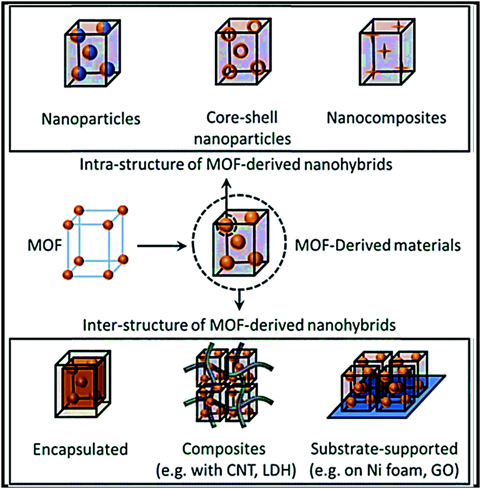 | ||
| Fig. 19 Variants of MOF-derived nanohybrids for energy-storage applications obtained via tuning either the internal or external structures, or a combination of both. Reproduced with permission.251 Copyright: 2018, Royal Society of Chemistry. | ||
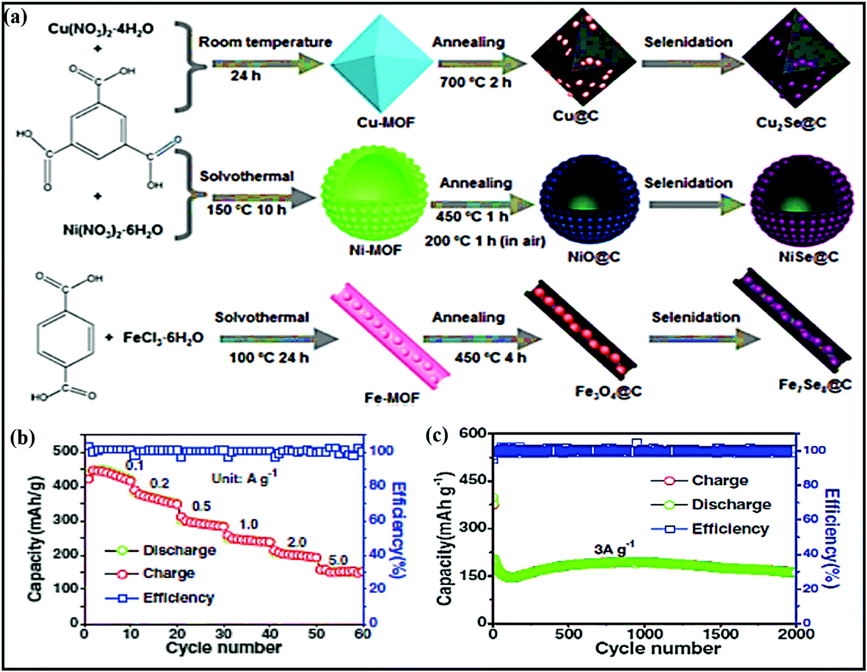 | ||
| Fig. 20 (a) A schematic illustration of the fabrication of MOF-derived Cu2Se@C porous octahedra, NiSe@C hollow microspheres, and peapod-like Fe7Se8@C nanorods. (b) The rate performance from 0.1 to 5 A g−1 and (c) the cycling performance of NiSe@C hollow spheres at 3 A g−1. Reproduced with permission.252 Copyright: 2018, Wiley-VCH Verlag GmbH & Co. KGaA. | ||
Wei Shuang et al.255 carried out the novel sulfuration of Ni-based MOFs and polypyrrole (PPy) coating strategies to achieve a N-doped carbon shell-confined Ni3S2 composite anode (the synthesis involves the solvothermal synthesis of Ni-MOF, the sulfuration of Ni-MOF to obtain the NiSx precursor, the coating of PPY onto NiSx, and annealing at 600 °C to achieve NiSx@C-600) (∼1.2 V vs. Na/Na+) (Fig. 21a) with a high specific capacity of 432.8 mA h g−1 for up to 100 cycles and high rate capabilities of 317.6 mA h g−1 at a rate of 6.4 A g−1 with a high capacitive contribution (90.78% at 0.6 mV s−1) (Fig. 21b). In this work, the authors believed that PPy in the N-doped carbon shell during the annealing process protects the nanosized particles from aggregation. Meanwhile, the nanosized architecture improved the reaction kinetics and shielded against volume changes. N-Doped carbon improves the electronic conductivity via connecting short electronic pathways and buffering volume changes during the conversion-based mechanism. In another instance, a 2D derived NiSe2/N-rich carbon composite anode (∼1.5 V vs. Na/Na+)256 prepared from a Ni-hexamine MOF through pyrolysis and a subsequent selenization process showed a reversible capacity of 410 mA h g−1 at 1 A g−1, with a capacity of 240 mA h g−1 even after 1000 cycles at 5 A g−1.
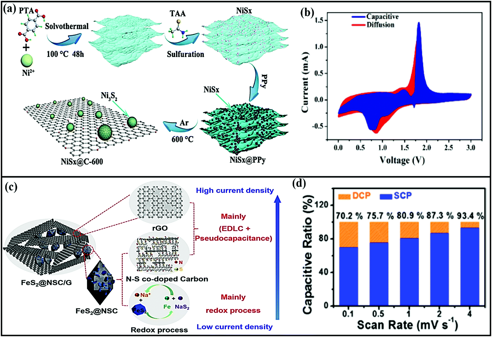 | ||
| Fig. 21 (a) A schematic diagram of the fabrication of NiSx@C-600 and (b) the capacitive and diffusion contributions to charge storage at 0.6 mV s−1. Reproduced with permission.255 Copyright: 2019, Elsevier. (c) A schematic illustration of the FeS2@NSC/G sodium storage mechanisms of the three components at different current densities and (d) a bar chart of the capacitive ratios at various scan rates (from 0.1 to 4.0 mV s−1). Reproduced with permission.257 Copyright: 2018, American Chemical Society. | ||
Meng Shao et al.257 designed a MOF-derived FeS2@C composite that has a dominant capacitive contribution (the surface contribution ratio is around 70.0% at 0.1 mV s−1). In battery-based analysis, the FeS2@NSC/G composite demonstrated improved rate capabilities of 200 mA h g−1 even at 10 A g−1. Sodium storage takes place via diffusion as a result of the redox properties at low current densities and the surface contribution at higher current densities (Fig. 21c and d). A CuO/Cu2O-GPC hybrid material258 derived from a Cu-based MOF via a one-step thermal transformation process demonstrated favorable electrochemical performance in both LIBs and SIBs. In SIB applications, the CuO/Cu2O-GPC composite anode (∼0.75 V vs. Na/Na+) recorded a stable discharge capacity of around 330 mA h g−1 at 50 mA g−1, and this was maintained at 303 mA h g−1 after cycling for up to 200 cycles with a conversion-type mechanism. In another instance, MOF-derived NiS2 anode hollow spheres encased in a graphene layer259 (during the process, the in situ formed graphene layer is thinly coated on the surface of nanosized NiS2) also showed a high reversible capacity of 1027 mA h g−1 and after 100 cycles a discharge capacity of 848 mA h g−1 was maintained at 0.1 A g−1 with excellent rate performance (a capacity of 527.8 mA h g−1 was obtained at 2 A g−1). This enhanced electrochemical performance could be due to an optimized unique structure and the highly graphitized carbon coating layers.
Xinye Liu et al.260 prepared a unique binary-MOF-derived hierarchical hollow Ni3S2/Co9S8/N-doped carbon hybrid composite anode (∼1.2 V vs. Na/Na+) via a carbonization and sulfurization strategy with different reaction times. A specific capacity of 419.9 mA h g−1 was reported at a current density of 0.1 A g−1 after 100 cycles (the initial discharge capacity was around 554 mA h g−1) through a conversion- and intercalation-based mechanism. In addition, good rate performance was seen (specific capacities of 416.7 and 347.8 mA h g−1 at current densities of 0.05 and 1 A g−1, respectively, were recorded, and even at 2 A g−1, it takes only 15 min to achieve a capacity of 323.2 mA h g−1), and 92% capacity retention was seen after 300 cycles. An Fe2O3@MIL-101(Fe)/C hierarchical hollow hybrid261 anode was also reported with improved electrochemical performance. A stable reversible capacity of 710 mA h g−1 was achieved with 93.2% capacity retention (a capacity of 662 mA h g−1 is retained) after 200 cycles with high rate performance through a conversion-based mechanism. The intrinsic hollow nanostructure architecture accommodates volume changes during (de)sodiation cycling.
The representative physical properties, capacity values, rate capabilities, and cycling performance data of MOF-derived composite materials are summarized in Table 4.
| Composite material | Method | BET SA (m2 g−1) | Voltage window vs. Na/Na+ (V) | Discharge capacity (mA h g−1) | Rate capabilities (mA h g−1) | Capacity retention | Ref. |
|---|---|---|---|---|---|---|---|
| ZnSe-NC@CoSe2-NC | Solution mixing | 100.18 | 0.005 to 3.0 | 882.6 at 0.1 A g−1 | 568 and 187 at 0.1 and 1.6 A g−1, respectively | 308 mA h g−1 after 150 cycles at 0.1 A g−1 | 262 |
| AGC-CoS2@NCNFs | Electrospinning | 107 | 0.01 to 3.0 | 876 at 100 mA g−1 | 425 and 201 at 100 and 3200 mA g−1, respectively | 148 mA h g−1 at a current density of 3.2 A g−1 over 1000 cycles | 263 |
| Co9S8@carbon | Precipitation | 1273 | 0.2 to 2.5 | 631 at 100 mA g−1 | 547 and 100 at 0.2 and 10.0 A g−1, respectively | 84.5% after 800 cycles at 10.0 A g−1 | 67 |
| Co3O4/N–C | Solvothermal and annealing | 30 | 0.01 to 3.0 | 229 within 150 cycles at 1 A g−1 | 818 and 529 at 0.1 and 5 A g−1, respectively | ∼620 mA h g−1 after 2000 cycles at 1 A g−1 (86.4% capacity retention) | 264 |
| Se/CoSe2/C | Hydrothermal | 3 | 0.5 to 3.0 | 663 at 0.1 A g−1 | 490 and 228 at 0.1 and 5 A g−1, respectively | ∼350 mA h g−1 at 2 A g−1 after 700 cycles | 265 |
| CoSe2@N-PGC/CNTs | Precipitation | 22.8 | 0.001 to 3.0 | 601 at 0.2 A g−1 | 482 and 368 at 0.2 and 5 A g−1, respectively | ∼424 mA h g−1 at 0.2 A g−1 after 100 cycles | 266 |
| Fe7S8/C | Solvothermal | — | 0.001 to 3.0 | 802 at 100 mA g−1 | 583 and 216 at 0.1 and 6.4 A g−1, respectively | ∼301 mA h g−1 after 1000 cycles at 1 A g−1 | 267 |
| NiO/Ni/graphene composite | Solvothermal | 104 | 0.005 to 3.0 | 992 at 100 mA g−1 | 385 and 207 at 200 and 2000 mA g−1, respectively | No capacity loss after 1000 cycles | 268 |
| P-Doped NiS2/C | Hydrothermal, sulfidation, and carbonization | ∼46.167 | ∼0.001 to 3.0 | 3546.7 at 0.1 A g−1 | 1601.4 and 557.2 at 0.1 and 2 A g−1, respectively | 766.8 mA h g−1 after 400 cycles at 0.5 A g−1 | 269 |
| FeS/C composite | Hydrothermal sulfurization and thermal reduction | — | 0.01 to 3.0 | 809 at 1 A g−1 | 632 and 249 at 0.1C and 5C, respectively | 77.3% after 100 cycles at 1 A g−1 | 270 |
| FeSe2@rGO | Hydrothermal and selenylation | 48.015 | 0.01–3.00 | 392 at 5 A g−1 | ∼558.5 and 455.1 at 0.1 and 2.0 A g−1, respectively | 350 mA h g−1 after 600 cycles at 5.0 A g−1 | 271 |
| MnS–(ZnCo)S/N–C | Gas–solid reaction | — | 0.0 to 3.0 | 770 at 0.05 A g−1 | 427 and 170 at 0.1 and 10 A g−1, respectively | 89.1% after 400 cycles at 1 A g−1 | 272 |
| N–ZnSe@rGO | Pyrolysis | 54.8 | 0.01 to 3.0 | 836 at 100 mA g−1 | 779 and 338 at 200 and 5000 mA g−1, respectively | 91% after 1000 cycles at 2000 mA g−1 | 273 |
| Co(Ni)Se2@NCC | — | 54.19 | 0 to 2.5 | 1323 at 0.1 A g−1 | 774 and 720 at 0.2 and 1 A g−1, respectively | (>85%) 735 mA h g−1 after 100 cycles at 0.1 A g−1 | 274 |
| Sn4P3@NPC | Solvothermal | — | 0.01 to 3.0 | 622 at 0.1 A g−1 | 365 and 146 at 0.1 and 2 A g−1, respectively | 319 mA h g−1 at 0.1 A g−1 after 100 cycles | 275 |
| Fe7S8/N-doped carbon nanohybrids | Solvothermal | — | 0.01 to 3.0 | 632 at 200 mA g−1 | 467 and 327 at 50 and 3200 mA g−1, respectively | 99.3% after 500 cycles at 500 mA g−1 | 276 |
| ZnS/rGO composite | Refluxing and annealing | 139.7 | 0.01 to 3.0 | 572 at 100 mA g−1 | 599 and 238 at 0.1 and 5 A g−1, respectively | 362 mA h g−1 at 1 A g−1 after 300 cycles | 277 |
| Co9S8/MoS2-CN | Solvothermal | 13.78 | 0.0 to 3.0 | 840 at 0.5 A g−1 | 840 and 275 at 0.5 and 20 A g−1, respectively | 93.2% after 250 cycles at 2 A g−1 | 278 |
| ZnO/rGO/C composite | Carbonization | 128.33 | 0.01 to 2.5 | 1579.6 at 0.05C | 162 and 100 at 0.2C and 0.4C, respectively | 300 mA h g−1 after 100 cycles | 279 |
| ZnS–Sb2S3@C | Sulfurization | — | 0.01 to 1.8 | 1675 at 100 mA g−1 | 1043 and 390 at 100 and 800 mA g−1, respectively | 630 mA h g−1 at 100 mA g−1 after 120 cycles | 280 |
| MoSe2/N-PCD | Annealing and hydrothermal | — | 0.01–3.00 | 464 at 0.2 A g−1 | 539 and 266 at 0.1 and 2 A g−1, respectively | 223 mA g−1 after 1000 cycles (capacity retention of ∼83%) | 281 |
| Ga2S3/C-PSM | Vacuum heat treatment and sulfuration | 90.5 | 0.01–2.5 | 1070 at 100 mA g−1 | 523 and 94 at 100 and 2000 mA g−1, respectively | 385 mA h g−1 after 200 cycles at 100 mA g−1 | 282 |
| CC@CN@MoS2 | Thermal treatment and hydrothermal process | — | 0.01–3.00 | 653.9 (second cycle) at 200 mA g−1 | 660 and 235 at 0.1 and 2.0 A g−1, respectively | 265 mA h g−1 after 200 cycles (75.3% retention rate) | 283 |
| G-NC@TiO2 | Solvothermal and calcination | 154.8 | 0.05–2.00 | 120 | 336 and 117 at 20 and 1000 mA g−1, respectively | 93% after 5000 cycles | 284 |
| RGO@CoP@FeP | Phosphorization | 55.6 | 0.01–3.00 | 968.0 at 100 mA g−1 | 480.2 and 374.6 at 0.1 and 1 A g−1, respectively | 285 mA h g−1 after 200 cycles at 100 mA g−1 | 285 |
| CoSnO3-NC | Carbonization | 526 | 0.01–3.00 | 733.8 at 0.1 A g−1 | 519.2 and 168.1 at 0.1 and 5 A g−1, respectively | 273.8 mA h g−1 after 1000 cycles at 1 A g−1 | 286 |
| CoNi2S4@C | Hydrothermal and calcination | 4.54 | 0.01–3.00 | 673.4 at 100 mA g−1 | 544 and 278 at 50 and 2000 mA g−1, respectively | 438 mA h g−1 after 50 cycles at 100 mA g−1 | 287 |
| Co3(NO3)2(OH)4@Zr-MOF@RGO | Solvothermal method followed by spray drying | 33 | 0.01–3.00 | 555 at 0.1 A g−1 | 555 and 340 at 0.1 and 1 A g−1, respectively | 525 mA h g−1 after 100 cycles (capacity retention of 94.3%) | 288 |
| Bi2S3@Co9S8/NC | Carbonization and sulfidation | — | 0.01–3.00 | 597 after 100 cycles at 0.1 A g−1 | 574 and 367 at 0.2 and 5 A g−1, respectively | 458 mA h g−1 after 1000 cycles (capacity retention of 95.2%) | 289 |
| P@N-MPC | Carbonization, vaporization, and condensation | 67.9 | ∼0.01–2.7 | ∼600 at 0.15 A g−1 | 684 and 291 at 0.3 and 9 A g−1, respectively | 450 mA h g−1 after 1000 cycles (0.02% capacity loss/cycle) | 290 |
| Ni-doped Co/CoO/NC | Calcination | 552 | 0.01–3.00 | ∼218 at 500 mA g−1 | 307 and 110 at 0.1 and 5 A g−1, respectively | 218.7 mA h g−1 after 100 cycles at 0.5 A g−1 | 291 |
| V2O3/C | Solvothermal and calcination | 258.954 | 0.01–3.00 | 425 (second cycle) at 50 mA g−1 | 417 and 149 at 50 and 2000 mA g−1, respectively | 181 mA h g−1 after 1000 cycles with a fade rate of 0.032%/cycle | 292 |
| CNT/CoSe2@NC | Acid treatment and selenization | 36.68 | ∼0.01–3.00 | 686 at 0.2 A g−1 | 480 and 363 at 0.2 and 5 A g−1, respectively | 83 mA h g−1 after 120 cycles at 0.2 A g−1 | 293 |
| CoSe2@NC-NR/CNT | Spray pyrolysis and selenization | 76.8 | 0.001–3 | 926 at 0.2 A g−1 | 645 and 517 at 0.2 and 5 A g−1, respectively | 555 mA h g−1 after 100 cycles at a current density of 0.2 A g−1 | 294 |
| MoS2/C | Sulfuration and heating | 51.04 | 0.01–3 | 972 at 100 mA g−1. | 535 and 242 at 0.1 and 5 A g−1, respectively | 128 mA h g−1 after 5000 cycles at 2 A g−1 (with a fade rate of 0.036%/cycle) | 295 |
| ZnSe-NC@CoSe2-NC | Precipitation, coating, carbonization, and selenization | 100.18 | 0.005–3.0 | 882.6 at 0.1 A g−1 | 568.6 and 187.5 at 0.1 and 1.6 A g−1, respectively | 308.5 mA h g−1 after 150 cycles at 0.1 A g−1 | 262 |
| ReS2/C | Pyrolysis and leaching | 117.40 | 0.01–2.50 | 365 at 100 mA g−1 | 365 and 145 at 100 and 2000 mA g−1, respectively | 100 mA h g−1 after >600 cycles at 2 A g−1 | 296 |
| Co3O4@N-CNFs | Annealing | — | ∼0.01–3.0 | 864.2 and 450 at 50 and 100 mA g−1, respectively | 520 and 205 at 100 and 3200 mA g−1, respectively | 220.1 mA h g−1 after 1000 cycles at 1.6 A g−1 | 297 |
| CoSe/C | Annealing | 134.5 | 0.01–3 | — | 597.2 and 361.9 at 0.2 and 16 mA g−1, respectively | 552.5 mA h g−1 (from the second cycle), retaining 531.6 mA h g−1 after 50 cycles at 500 mA g−1 | 298 |
| NG@SnSe/C | Thermal treatment and CVD | — | 0.01–2.5 | 650 at 0.05 A g−1 | 287.8 at 5 A g−1 | 500.6 mA h g−1 (from the second cycle) after 100 cycles at 0.2 A g−1 | 299 |
| FeF2@GC | Carbonization and hydrothermal | — | 0.8–4.5 | 611.4 at 50 mA g−1 | 304.2 and 5.5 at 0.05 and 10 A g−1, respectively | 87.0 mA h g−1 (fade rate of 0.041%/cycle) after 1000 cycles at 300 mA g−1 | 300 |
| P-NiSe@C | Hydrothermal, CVD, and calcination | — | 0.01–3.00 | 784.9 at 200 mA g−1 | 636.8 and 488.9 at 0.1 and 2 A g−1, respectively | 598.2 mA h g−1 after 100 cycles | 301 |
| Fe7S8/NSC | Pyrolysis | 234.8 | 0.01–3.00 | 731.9 at 0.5 A g−1 | 543.9 and 417.9 at 0.2 and 20 A g−1, respectively | 426.6 mA h g−1 after 1000 cycles at 5 A g−1 | 302 |
| V2O3/N-doped porous carbon | Pyrolysis | 99.87 | 1.0–4.0 | 180.9 (fifth cycle) at 1.0 A g−1 | 323.4 and 109 at 25 mA g−1 and 10 A g−1, respectively | 134.5 mA h g−1 after 3000 cycles (74.4% retention) at 1.0 A g−1 | 303 |
| Fe7S8@C-G | Salfurization | — | 0.01–3.00 | — | 463 and 306 at 0.1 and 2 A g−1, respectively | 478 mA h g−1 after 100 cycles at 100 mA g−1 | 304 |
| SnSe2@C | Carbonization and selenylation | 9.45 | 0.01–2.5 | 493 after 80 cycles at 0.5 A g−1 | 416 and 324 at 0.1 and 2 A g−1, respectively | 182.7 mA h g−1 after 1000 cycles at 5 A g−1 | 305 |
| MnS/C | Annealing | 185.23 | 0.005–3 | 297 after 100 cycles at 50 mA g−1 | 173.9 and 143.1 at 1 and 2.5 A g−1, respectively | 148.3 mA h g−1 after 5000 cycles at 1 A g−1 | 306 |
6.2. Polymeric nanocomposites of inorganic materials
In this section, we discuss mainly conducting-polymer-based binary or ternary composites with different inorganic materials and their synergistic interactions that improve the sodium-ion storage performance. Conducting polymers such as polyaniline (PANI), polypyrrole (Ppy), and poly(3,4-ethylenedioxythiophene) (PEDOT) are well known for electrochemical energy storage applications, both in supercapacitors and rechargeable batteries.307 They offer high conductivity for facile charge transport, high porosity for electrolyte infiltration, and network structures with flexibility to buffer volume changes of active material during (de)sodiation, remaining interconnected, thereby improving the capacity, rate capability, and cycling stability when present in composite electrodes.Liao et al.308 demonstrated that the electrochemical performance of layered titanate negative electrodes can be significantly improved upon the insertion of PANI, which acts as conductive pillars to increase the interlayer spacing, facilitate charge transfer, and provide structural stability. A PANI-incorporating protonated titanate electrode annealed at 600 °C could form TiO2-coated polyaniline intercalated layered titanate (Fig. 22a–c), which exhibited a high specific capacity of 191 mA h g−1 at a current density of 1 A g−1, accompanied by good rate performance, with discharge capacities of 257 and 151 mA h g−1 at 0.05 and 5 A g−1, respectively (Fig. 22d). Werner et al.309 demonstrated a high-performance SIB cathode via electropolymerizing PANI thin film coated onto a carbon-coated oxygen-deficient anatase TiO2 nanotube (TiO2−x–C NT) array, which was prepared via a one-step anodic oxidation process and subsequent annealing at high temperature. The high surface area of TiO2−x–C NTs and the favorable organized nanostructure caused good adhesion between the TiO2−x–C NTs and PANI, which synergistically improved the capacity, rate capability, and cycling stability of the composite cathode compare to the cathode without PANI.
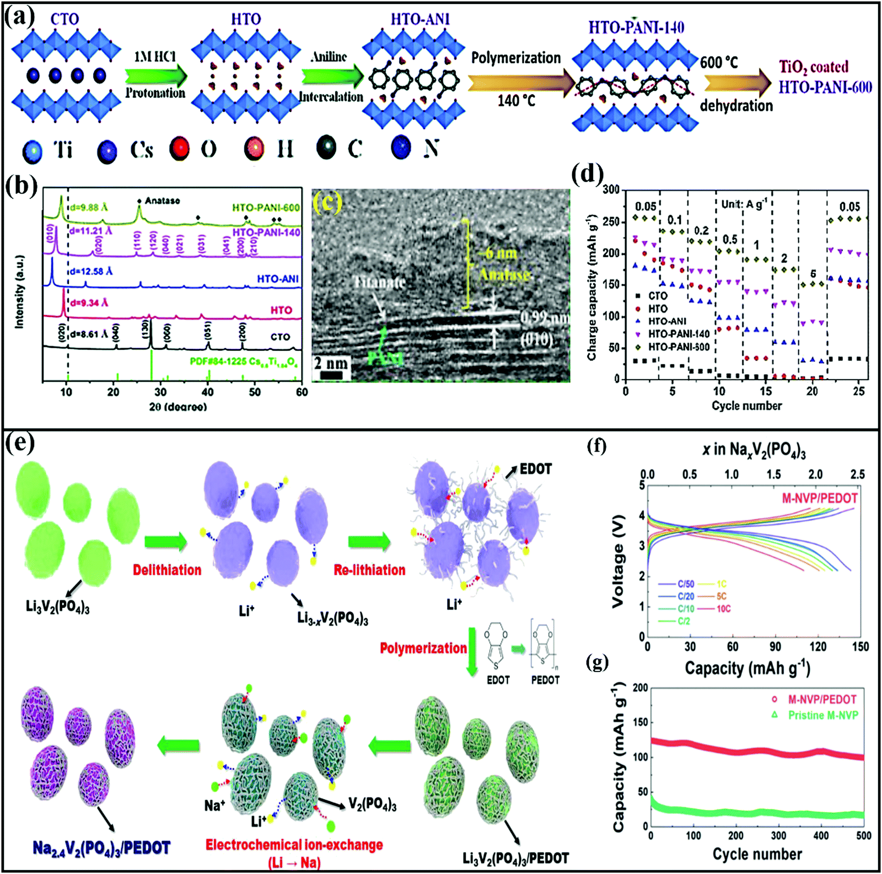 | ||
| Fig. 22 (a) A schematic illustration of the synthesis of TiO2-coated polyaniline intercalated layered titanate (HTO-PANI 600) starting from layered CsxTi(2−x/4)□x/4O4 (□ stands for a vacancy) followed by an ion-exchange reaction with HCl to form protonated titanate (HTO), followed by ultrasonication-assisted aniline insertion into HTO (HTO-ANI), followed by in situ polymerization to form hydrated HTO-PANI, with a subsequent dehydration step at 600 °C. (b) The XRD patterns obtained from the modified layered titanates at different stages of synthesis, showing an increase in the d spacing with PANI insertion. (c) A TEM image of HTO-PANI-600 and (d) a rate capability study showing the improved capacity of HTO-PANI-600 over other materials. Reproduced with permission.308 Copyright: 2020, Royal Society of Chemistry. (e) A schematic illustration of the synthesis process of the monoclinic Na2.4V2(PO4)3/PEDOT composite. (f) Charge discharge profiles at different C rates for the Na2.4V2(PO4)3/PEDOT cathode and (g) a comparison of the cycling stabilities of Na2.4V2(PO4)3/PEDOT and pristine Na2.4V2(PO4)3. Reproduced with permission.314 [10.1039/C8TA06238B] Copyright: 2018, Royal Society of Chemistry. | ||
Liu et al.310 demonstrated that the structural degradation of CoS2 can be significantly reduced in a rationally designed electrode via encapsulating it in hierarchical porous rGO, followed by coating with polypyrrole thin film via a simple hydrothermal route, followed by a vapor polymerization reaction. The ternary composite showed a higher specific capacity of 554 mA h g−1 at 2.0 A g−1 (compared to 495 mA h g−1 for a CoS2@rGO electrode) accompanied by cycling stability, with 65.8% capacity retention after 700 cycles. Wang et al.131 demonstrated the improved electrochemical performance of a MoS2 anode via encapsulating it with N-doped porous hollow carbon spheres and coating with PPy. After an initial irreversible capacity loss, the ternary composite anode exhibited a high specific capacity of 713 mA h g−1 at a low current density of 0.1 A g−1 for 100 cycles, and it maintained a high capacity of 294 mA h g−1 at 5 A g−1 for 500 cycles.
A thin-layer coating of PEDOT or PEDOT:PSS311 conducting polymers onto Prussian blue analogs via in situ polymerization or simple overlaying has been reported to elevate the electrochemical performance of PB electrodes via favourable synergistic interactions, improving the charge transfer kinetics, preventing metal dissolution, and protecting the structure from pulverization. Benefiting from such structural reinforcement, Wang et al.312 reported high cycling stability, with 78.2% capacity retention after 1000 cycles, using a manganese hexacyanoferrate@PEDOT cathode. The unique features of PEDOT for stabilizing active electrode materials have been realized in many other cases. Jongsoon Kim and coworkers demonstrated that an ultrathin coating layer of PEDOT on a polyanionic compound, for example, Na2FePO4F313 or Na2.4V2(PO4)3,314 can address the poor conductivity and improve the power performance and cycling stability of devices. A partially desodiated phase, Na2−xFePO4F, or delithiated phase, Li3−xV2(PO4)3, can accelerate the polymerization of EDOT to PEDOT, forming a nanolayer PEDOT coating. The follow-up re-insertion of sodium or lithium followed by ion exchange with sodium could form Na2FePO4F and Na2.4V2(PO4)3 uniformly coated with PEDOT. Notable, at a high rate (10C) Na2.4V2(PO4)3/PEDOT and Na2FePO4F/PEDOT electrodes showed high specific capacities of 109.8 mA h g−1 and 76.1 mA h g−1, respectively, which were ∼8.5–10 times higher than those shown by uncoated electrodes. A schematic illustration of the synthesis process of the Na2.4V2(PO4)3/PEDOT composite and electrochemical performance data are shown in Fig. 22e–g. Karthikeyan et al.315 demonstrated a cobalt-free O3-Na[Ni1/3Mn1/3Fe1/3]O2 (NNMF) cathode, which, when embedded in a PANI matrix, could be operated at a high operating voltage of 2–4.5 V (in contrast to 2–4.2 V for the NNMF cathode alone), leading to a high energy density of 567 W h kg−1 accompanied by excellent cycling stability, with ∼75% capacity retention after 750 cycles at 2 A g−1.
7. Non-carbonaceous metal composites
Similar to carbonaceous metal composites, non-carbonaceous metal composites and/or hybrids offer improved structural stability and improved electrochemical performance without sacrificing capacities. Therefore, composite routes could be an easy way to make use of the intrinsic qualities of two or more precursors/sources via tuning the physical, chemical, and electrochemical properties. Based on works from the literature, various metal–metal composites and/or hybrids and rational design strategies adopted for the advancement of SIBs are highlighted in this section.Nana Wang et al.316 prepared double-walled Sb@TiO2-x nanotubes as a composite anode via hydrolysis, calcination, and a facile reduction process, and the material showed superior high-rate performance and cycle life in SIBs and LIBs. With the advantages of a hollow structure and nanoscale size, the composite shows a maximum discharge capacity as high as ∼520 mA h g−1 in a fluoroethylene carbonate electrolyte, and the composite retained a capacity of ∼300 mA h g−1 even after 1000 cycles, which is much higher than pure Sb NPs (∼20 mA h g−1) and TiO2-x (∼130 mA h g−1) at 2.64 A g−1. The advantages of the synergetic effect and distinctive interactions between Sb/TiO2-x and the 1D tubular structure morphology remain during cycling. A novel 1D yolk–shell Sb@Ti–O–P nanostructure317 was prepared via reducing the core–shell Sb2O3@TiO2 nanorod anode (∼0.8 V vs. Na/Na+) with NaH2PO2, and capacities of 805 and 360 mA h g−1 were reported at current densities of 0.1 and 10 A g−1, respectively, which are higher than the individual components alone. Further, the composite retains a capacity of 346 mA h g−1 even at 3 A g−1 for up to 300 cycles, which corresponds to a capacity retention of 88%. In this case, the authors state that the Sb nanorod architecture enhanced the capacity, the Ti–O–P shell stabilizes the interface between electrode and electrolyte, and the gap between the core and the shell accommodates large volume changes during the (de)sodiation process.
Dandelion-clock-inspired core–shell TiO2@MoS2318 was prepared via a facile solvothermal process. The novel composite provides strong structural integrity and facile electron transfer, prevents aggregation, and increases the number of active sites. As an anode material (∼1.1 V vs. Na/Na+) with an intercalation- and conversion-based mechanism, the composite showed a stable discharge capacity of ∼440 mA h g−1 at 0.1 A g−1, and the composite showed reversible capacities of 427.3 (10th cycle) and 277.8 (170th cycle) mA h g−1 at 0.1 and 10 A g−1, respectively. In cycling stability testing, the composite retains a capacity of 375.2 mA h g−1 even after 345 cycles, with approximately 100% capacity retention from the 6th cycle at 0.5 A g−1. Pure MoS2 and TiO2 failed in comparison with the composite.
Shuai Liu and co-researchers320 reported a phosphorous@Ni–P core@shell (RP@Ni–P) composite with different Ni–P shell thicknesses and compositions, and their structural stabilities and electrochemical performances were analyzed. More significantly, the authors demonstrated the advantages of the core@shell composite and described how the composite is beneficial for the ion/electron transport and sodium intercalation/de-intercalation processes. Indeed, the RP@Ni–P high-rate composite anode (∼0.4 V vs. Na/Na+) showed a capacity as high as 1256.2 mA h g−1 after 200 cycles at 260 mA g−1, superior rate performance (delivering a capacity of 491 mA h g−1 even at a current density of 5200 mA g−1), and admirable cycling stability, with a capacity of 409.1 mA h g−1 after up to 2000 cycles at a current density of 5 A g−1. Distinct core–shell Sb@Co(OH)2 nanosheets321 were fabricated via the magnetron sputtering of Sb onto a Co(OH)2 substrate anchored onto stainless steel mesh. As an anode (∼0.75 V vs. Na/Na+), through an alloy-type mechanism, the composite reported a high discharge capacity of as high as 972.6 mA h g−1 at 0.2 A g−1, with high rate performance (delivering a capacity of 383.5 mA h g−1 even at 30 A g−1). Novel core–shell Sb@Co(OH)2 not only facilitates ion/electron transfer but also buffers volume changes and aggregation. Subsequently, 3D Sb–Co nanocomposites322 for Na-ion and K-ion battery applications were also reported with good capacities and rate performances. The 3D porous architecture with a strong synergetic effect improves the overall electrochemical performance, and the incorporation of a Co element buffers volume expansion, alleviates mechanical stress, and improves the electrode kinetics.
It is well known that MXens have recently been widely reported as superior electrode materials for energy storage applications due to their high theoretical capacities, high electronic conductivities, abundant functional groups, and flexible plasticity.323–325 Therefore, rationally integrating MXens with other metal oxides can achieve unconventional functionalities with improved electrochemical performance that cannot be obtained using pristine (bare) materials. For instance, Jimei Huang et al.319 prepared novel sandwich-like Na0.23TiO2/Ti3C2MXene composites (1D amorphous Na0.23TiO2 nanobelts grown on 2D Ti3C2 nanosheets) via a one-step in situ transformation reaction (which consisted of etching with HF, the partial oxidation of Ti3C2 layers using dissolved O2 in NaOH, and in situ transformation to Na0.23TiO2 nanobelts to achieve sandwich-like Na0.23TiO2/Ti3C2MXene composites) (Fig. 23a and b).
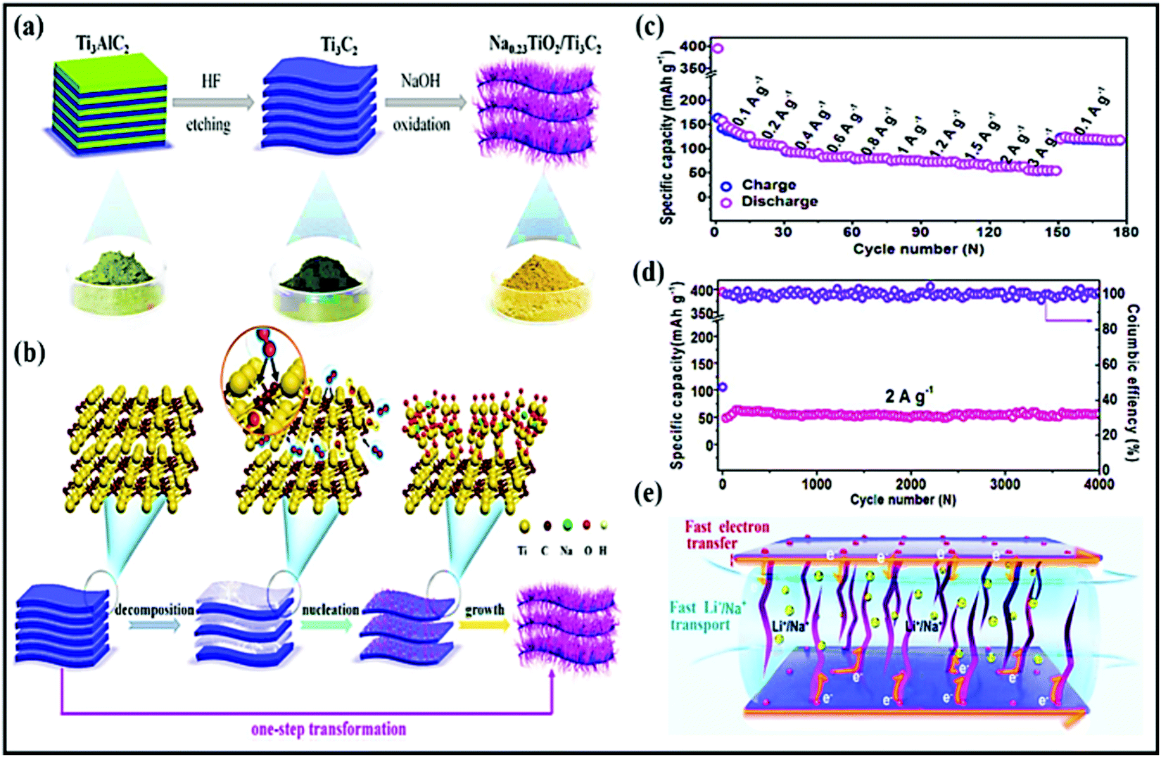 | ||
| Fig. 23 (a) A schematic representation of the synthetic route to the sandwich-like Na0.23TiO2/Ti3C2 composite and (b) a schematic illustration of the formation mechanism of the sandwich-like Na0.23TiO2/Ti3C2 composite through an in situ transformation reaction. (c) The rate performance, (d) long-term cycling performance, and (e) energy-storage mechanism during the discharge process using the Na0.23TiO2/Ti3C2 composite. Reproduced with permission.319 Copyright: 2018, Elsevier. | ||
As an anode material, a Na0.23TiO2/Ti3C2 MXene composite showed capacities of 138 and 47 mA h g−1 at 0.1 and 3 A g−1, respectively, and the composite retained a capacity of 56 mA h g−1 after up to 4000 cycles, with nearly 100% capacity retention (Fig. 23c and d). The novel sandwich-like composite composed of 1D and 2D architectures facilitates the charge-transport dynamics (Fig. 23e) and effectively relieves strain on the electrode during cycling. More significantly, Na0.23TiO2 nanobelts with ultra-small dimensions can reduce the diffusion length and buffer volume changes, while Ti3C2 nanosheets were electrically connected with Na0.23TiO2 and supported efficient 2D electron transfer. A distinctive two-step hydrothermal method for the in situ growth of hybrid NaT8O13/NaTiO2 nanoribbons on Ti3C2 MXene329 was reported, with the material showing good cycling stability. With an intercalation-type mechanism, the hybrid anode reported a stable voltage of ∼1.2 V and retained a capacity of 82 mA h g−1 even after 1900 cycles at 2 A g−1. In another instance, Feng Wu et al.326 reported a 3D VO2/MXene flower-like hybrid architecture to overcome solubility issues, low electronic conductivity, and significant volume changes during cycling. The resultant hybrid prepared via a facile hydrothermal method (which consists of etching, exfoliation, and mixing) (Fig. 24a) exhibited superior electrochemical performance through the combined effects of MXene and VO2. A reversible capacity of 280.9 mA h g−1 at 0.1 A g−1, a voltage of ∼1.25 V, and capacity retention of 141% over 200 cycles at 0.1 A g−1 (Fig. 24b) are seen, based on an intercalation-type mechanism. The high surface area and porous structure of this novel hybrid provide abundant active sites for sodium intercalation/de-intercalation. The flower-like hybrid structure also provided a high specific surface area that facilitated a greater degree of contact with the electrolyte and shortened the diffusion length via improving the electrode kinetics. Subsequently, a 2D phosphorene/Ti3C2Tx stable architecture with a fluorene hybrid interface327 (fabricated via a self-assembly process) (Fig. 24c–e) was also reported, with good sodium storage kinetics. The fluorene hybrid interface provided good mechanical support for stable and fast sodium storage. Indeed, the combined effects of 2D phosphorene nanosheets and Ti3C2Tx improved the electrode kinetics and alleviated volume variations, thereby enhancing the cycling performance. Electrochemically, the hybrid maintained capacities of 535 and 193 mA h g−1 at 0.1 and 5 A g−1, respectively, due to the large proportion of pseudocapacitive charge storage. In terms of cycling performance, the hybrid could be repeatedly cycled up to 1000 times and it retained a capacity of 298 mA h g−1 with 88% capacity retention. Chengxiang et al. also reported a heterostructured black phosphorous/Ti3C2 hybrid328 with improved storage performance. From DFT studies, they found that strong interactions between black phosphorous and Ti3C2 lower the binding energy to support the sodiation process. More significantly, the surface functional groups, such as –O, –F, and –OH, in Ti3C2 act as synergetic adsorption sites, accelerating sodiation and playing an important role in immobilizing black phosphorous (Fig. 23f–h). In a similar fashion, a Bi2S3/MXene sandwich-like stereochemical structure330 was reported with enhanced performance due to the high-capacity Bi2S3NPs and the high electrical conductivity of the Ti3C2Tx layers. As an anode material, the composite showed maximum/minimum discharge capacities of 407/168 mA h g−1 at 0.1/5 A g−1 and low capacity decay of only ∼0.22% per cycle for up to 250 (de)sodiation cycles. An optimized Si/TiN/Ti/Ge hybrid composite331 anode reported excellent electrochemical performance due to its novel 3D nanostructure and an effective conductive layer of TiN/Ti thin film. Theoretically, the adsorption and diffusion of sodium over the Si lattice was evidenced via first-principles calculations.
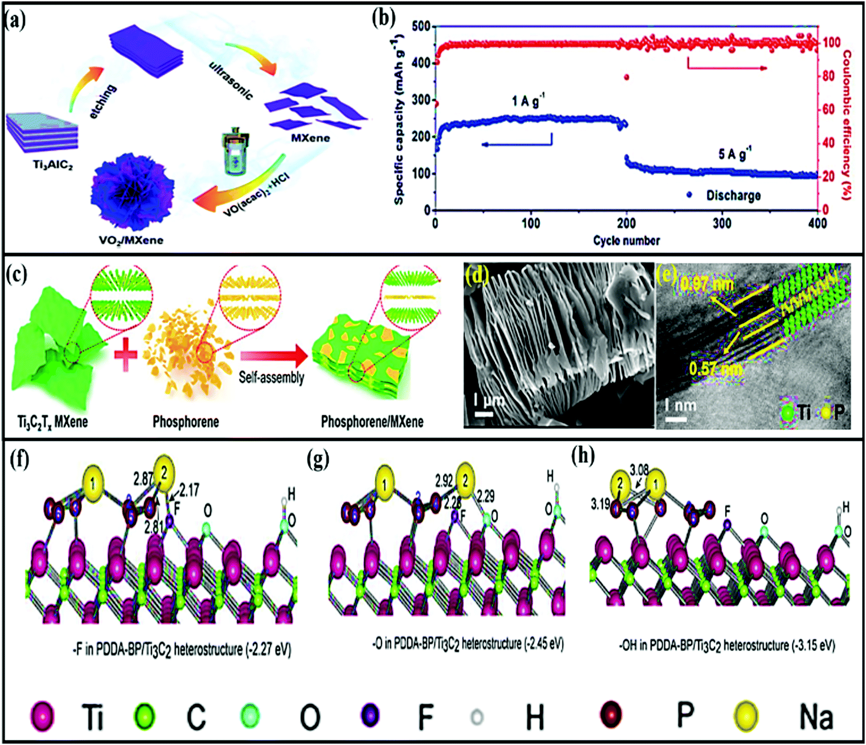 | ||
| Fig. 24 (a) A schematic illustration of the synthetic process for VO2/MXene hybrids and (b) the cycling performance of VO2/MX-1 at current densities of 1 and 5 A g−1. Reproduced with permission.326 Copyright: 2019, Royal Society of Chemistry. (c) A schematic illustration of the synthesis process for phosphorene/MXene hybrid structures. (d) An SEM image of etched-Ti3C2Tx. (e) A HRTEM image of the phosphorene/MXene architecture; the inset shows the corresponding atomic structural model. Reproduced with permission.327 Copyright: 2020, American Chemical Society. The sodiation process revealed via DFT calculations: (f–h) the most stable adsorption configurations for Na adsorption on top of functional heterostructure groups, such as –F, –O, and –OH. Reproduced with permission.328 Copyright: 2019, Elsevier. | ||
8. Conclusions and future scope
Although SIBs are considered as some of the most suitable alternatives to LIBs, their development for practical and large-scale applications has been hindered by poor electrochemical performance, mainly arising from the large size of Na+ and the lack of suitable electrode materials. In this review, we have summarized recent progress relating to rationally designed nanocomposite materials (both carbonaceous and non-carbonaceous) for use as electrodes aimed at improving the electrochemical performances of SIBs (Fig. 25).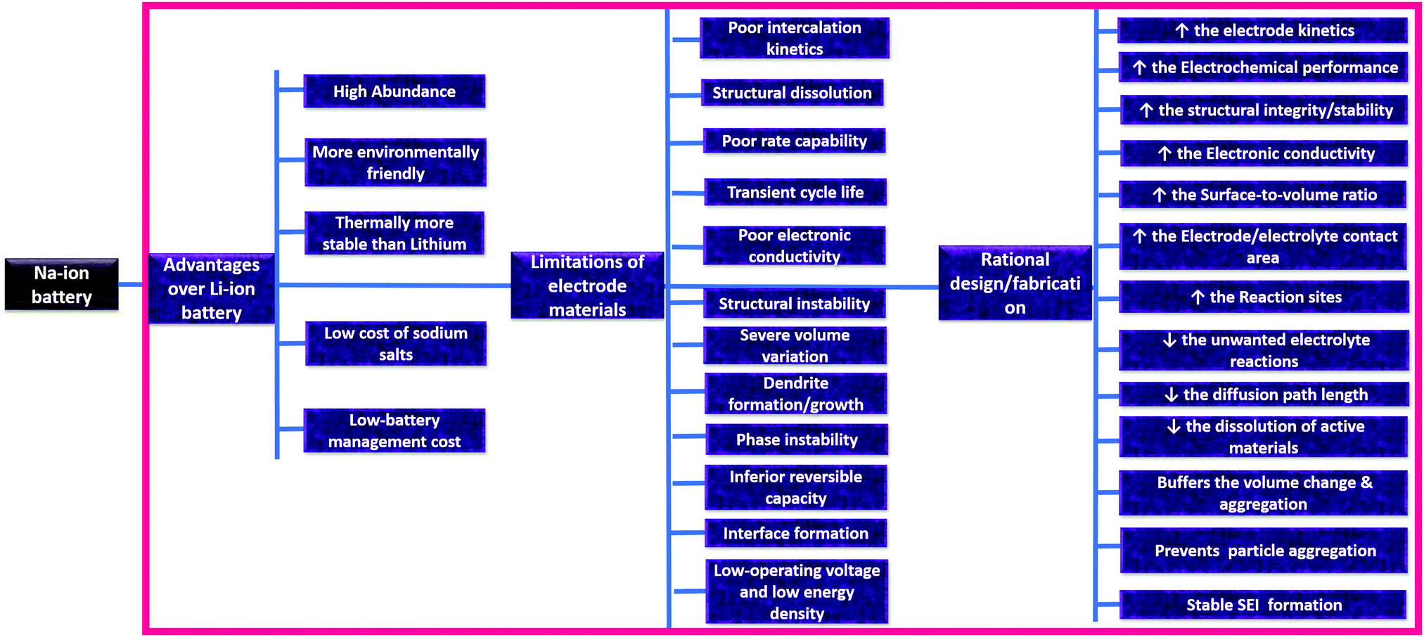 | ||
| Fig. 25 An overview of the advantages and limitations of Na-ion battery electrode materials and the merits of rational design/fabrication aimed at obtaining high electrochemical performance. | ||
In general, large numbers of available Na+ storage sites with facile solid-state Na+ diffusion, sufficient electronic conductivity for facile charge transfer, and flexibility to buffer huge volume changes during cycling are the most desired properties for any electrode material for SIBs. Notably, depending on the nature of the active material (inorganic or organic), much effort has been devoted to improving the electrochemical performance via optimizing crystal structures,332 nano-engineering,30 surface modifications,333 doping,334,335 creating vacancies,336 functionalization, extending conjugation,337,338etc. However, it is difficult to achieve all the beneficial properties for developing reliable practical batteries based on any single state-of-the-art investigated active material, and the task-specific design of nanocomposites where the components can synergistically overcome current limitations (the poor electronic conductivities of bare active materials, poor Na+ diffusion kinetics due to large sizes, and uncontrollable volume changes causing structural degradation during cycling) and obtain the aforementioned desired properties is a good approach. To summarize:
• The nanoengineering of active materials to achieve 0D, 1D, and 2D architectures with simultaneous composite formation with other active materials or conductive matrices has been found to be one of the most effective approaches for obtaining desired electrode performances in SIBs. Such engineered architectures not only increase the active surface area that is accessible to electrolytes for charge storage but, also, the open framework structures in such short-range ordered materials and enhanced interfacial connections can increase solid-state ion diffusion.
• Nanocomposites involving two or more active materials with engineered heterostructures (0D–2D, 0D–3D, 2D–2D, 1D–3D, etc.) can synergistically boost the electrochemical performance, resulting in improved electronic and kinetic properties. Engineered architectures, such as yolk–shell, core–shell with a hollow interior, and robust shell, are highly effective at stabilizing electrode architectures during cycling and improving the cycling stability.
• Connecting nanostructured active materials through porous conductive networks with high surface areas, carbonaceous materials (either synthesizing them in situ along with the active materials from soluble carbon precursors following post-processing or using engineered carbon substrates and directly anchoring the nanostructure active material to them) can not only maintain a conductive network throughout the material for facile charge transfer but they can also provide flexibility to buffer the effects of volume changes during cycling, prevent the agglomeration of particles, and maintain the structural integrity. Such porous nanocomposites also offer a significant capacitive contribution to the total charge storage.
• In the case of organic-material-based nanocomposite hybrids, the organic compounds are mostly physically adsorbed on carbon matrices through π–π interactions21,187,189,202,220 or chemically bonded to the carbon matrix.187,189,339,340 Therefore, the resulting heterogeneous (modified/rationally designed) hybrid structures exhibit unique structural and physicochemical properties different from the bulk forms. Such carbonaceous nanocomposite organic electrodes show reduced charge transfer resistance21,193 and increased electrode/electrolyte contact areas,202 prevent the dissolution of the active organic compound through stable chemical or non-covalent π–π stacking interactions,187,341 improve the electron transportation kinetics and diffusion properties,191,202,207etc.
• MOF-Derived composite materials fabricated via the simple pyrolysis of parent MOFs can produce well-defined metal compound (metals or metal oxides/sulfides/selenides/phosphides depending on the pyrolysis condition) NPs embedded in porous carbon matrix architectures. Such nanoarchitectures, with kinetically favorable large interstitial sites with ordered porosity, high conductivity, and high surface areas, are favorable for (de)sodiation when used as SIB electrodes.250
However, although the rational design of electrodes may boost the electrochemical performance, many challenges still remain. The performances of oxide-based materials in LIBs are quite outstanding, while the Na-storage performances are far from satisfactory, with low capacities and inferior cycling stabilities. It is a significant challenge to develop electrode materials with large interstitial spaces within their crystallographic structures that can host Na ions and achieve satisfactory electrochemical performance. Also, conversion- and alloying-based materials exhibit huge irreversible capacity losses. Furthermore, nanostructured materials exhibit high surface areas and low densities, accelerating electrolyte degradation and inevitably affecting the volumetric energy densities of these systems. Moreover, the unstable SEI layers formed during the first cycles induce the continuous consumption and trapping of Na ions during cycling with consequent low Coulombic efficiencies and quick capacity fading.
Based on the comprehensive analysis of rationally designed composite materials given in this review and the existing challenges, some possible future research directions are proposed for building reliable electrodes for use in SIBs.
• The rational design of layered electrode materials with chemical pre-intercalation or pillaring with foreign ions and molecules to improve the interlayer distance is a promising approach for improving Na+ diffusion coefficients, and it needs to be investigated in-depth and extensively.
• Robust core–shell or yolk–shell architectures can alleviate the cycling stability limitations of SIBs and require extensive investigation. In addition, compact void-free universal film formation strategies should be developed to enhance the volumetric energy densities of such electrodes.
• The structures and morphologies of parent MOFs and the transformation process greatly influence the structural, morphological, and compositional features and, in turn, the electrochemical performances of the derived products; in-depth analysis is required to develop synergistic interactions efficiently.
• A high-surface-area electrode often results in higher levels of electrolyte degradation; thus, the surface area should also be optimized. Along with the rational design of electrodes, pre-sodiation strategies should be adopted (especially for anodes) to overcome the loss of Na ions during SEI formation, which is a major cause of the initial low Coulombic efficiencies of SIBs.
• Mechanistic understanding of sodium ion transport and storage in nanocomposite electrodes and solid electrolyte interphase formation in SIBs is still at an early stage. Deep investigations of the specific electrochemical changes occurring in nanocomposite electrodes during cycling via different in situ techniques, like XRD, TEM, XAS, Raman spectroscopy, etc., and computational studies to correlate structural changes and the electrochemical performances of SIBs are needed for the future design of nanocomposite electrodes.
• The rational design of nanocomposite electrodes often involves multistep processes, which need to be reduced, and processes should be made cost-effective and compatible with industrial mass production. Moreover, even more complex nanocomposites with desired architectures and compositions need to be fabricated and tested for Na+ storage. In addition, more comprehensive studies (surface functionalities and reactions, electrode/electrolyte interfacial reactions and kinetics, defect analysis) are required to achieve high electrochemical performance.
• The behaviors of nanocomposite electrodes in high voltage aqueous electrolytes (water-in-salt electrolytes) and solid-state electrolytes have not been well explored. Considering the high safety of such electrolytes, detailed comprehensive studies of the structures at the interfaces and the Na+ transport and storage mechanisms should be carried out.
• Sodium-based dual-ion batteries also represent a promising and cost-effective technology; however, they have been relatively less explored, with challenges mainly arising due to the unavailability of suitable cathode materials and the degradation of conventional carbonate-based electrolytes at high voltages.342,343 Significant research should also be focused on designing sodium-based dual-ion batteries with high-performance electrodes with facile anion intercalation pathways, high structural integrity, and high voltage electrolyte combinations.
• Finally, computer simulations should be carried out for the rational design of future electrode materials to determine the most promising atomic configurations and interactions before attempting laboratory synthesis.
Conflicts of interest
There are no conflicts to declare.Acknowledgements
D. G. thanks SERB DST, India (ECR/2018/001039) for the research grant. D. G. and S. K. N. thank DST-Technology Mission Division, India (Ref No. DST/TMD/HFC/2K18/124(G)). S. K. N. thanks DST-Government of India, NANOMISSION PROJECT (SR/NM/NT-1073/2016) for financial support. S. K. N. thanks Talent Attraction Programme funded by the Community of Madrid Spain (2017-T1/AMB5610) for financial support.References
- T. Kim, W. Song, D.-Y. Son, L. K. Ono and Y. Qi, J. Mater. Chem. A, 2019, 7, 2942–2964 RSC.
- R. Marom, S. F. Amalraj, N. Leifer, D. Jacob and D. Aurbach, J. Mater. Chem., 2011, 21, 9938–9954 RSC.
- S. Goriparti, E. Miele, F. De Angelis, E. Di Fabrizio, R. Proietti Zaccaria and C. Capiglia, J. Power Sources, 2014, 257, 421–443 CrossRef CAS.
- M. Armand and J. M. Tarascon, Nature, 2008, 451, 652–657 CrossRef CAS PubMed.
- Z. Guo, S. Zhao, T. Li, D. Su, S. Guo and G. Wang, Adv. Energy Mater., 2020, 10, 1903591 CrossRef CAS.
- D. Chen, M. Lu, D. Cai, H. Yang and W. Han, J. Energy Chem., 2021, 54, 712–726 CrossRef.
- W. Zhang, J. Yin, W. Wang, Z. Bayhan and H. N. Alshareef, Nano Energy, 2021, 83 DOI:10.1016/j.nanoen.2021.105792.
- K. Zhang, K. O. Kirlikovali, J. M. Suh, J.-W. Choi, H. W. Jang, R. S. Varma, O. K. Farha and M. Shokouhimehr, ACS Appl. Energy Mater., 2020, 3, 6019–6035 CrossRef CAS.
- N. Wu, W. Yao, X. Song, G. Zhang, B. Chen, J. Yang and Y. Tang, Adv. Energy Mater., 2019, 9, 1803865 CrossRef.
- R. Nagaraj, S. Pakhira, K. Aruchamy, P. Yadav, D. Mondal, K. Dharmalingm, N. Sanna Kotrappanavar and D. Ghosh, ACS Appl. Energy Mater., 2020, 3, 3425–3434 CrossRef CAS.
- J.-Y. Hwang, S.-T. Myung and Y.-K. Sun, Chem. Soc. Rev., 2017, 46, 3529–3614 RSC.
- Z. Dai, U. Mani, H. T. Tan and Q. Yan, Small Methods, 2017, 1, 1700098 CrossRef.
- N. Yabuuchi, K. Kubota, M. Dahbi and S. Komaba, Chem. Rev., 2014, 114, 11636–11682 CrossRef CAS PubMed.
- Y. Zhang, X. Xia, B. Liu, S. Deng, D. Xie, Q. Liu, Y. Wang, J. Wu, X. Wang and J. Tu, Adv. Energy Mater., 2019, 9, 1803342 CrossRef.
- L. Yu, L. P. Wang, H. Liao, J. Wang, Z. Feng, O. Lev, J. S. C. Loo, M. T. Sougrati and Z. J. Xu, Small, 2018, 14, 1703338 CrossRef PubMed.
- A. Eftekhari and D.-W. Kim, J. Power Sources, 2018, 395, 336–348 CrossRef CAS.
- A. Eguia-Barrio, E. Castillo-Martínez, F. Klein, R. Pinedo, L. Lezama, J. Janek, P. Adelhelm and T. Rojo, J. Power Sources, 2017, 367, 130–137 CrossRef CAS.
- J.-H. Kim and D. K. Kim, J. Korean Ceram. Soc., 2018, 55, 307–324 CrossRef CAS.
- C. Wang, Y. Xu, Y. Fang, M. Zhou, L. Liang, S. Singh, H. Zhao, A. Schober and Y. Lei, J. Am. Chem. Soc., 2015, 137, 3124–3130 CrossRef CAS PubMed.
- A. Sabir, T. Zia, M. Usman, M. Shafiq, R. U. Khan and K. I. Jacob, Self-standing Substrates, 2020, ch. 12, pp. 353–368 DOI:10.1007/978-3-030-29522-6_12.
- M. Chen, C. Yang, Z. Xu, Y. Tang, J. Jiang, P. Liu, Y. Su and D. Wu, RSC Adv., 2016, 6, 13666–13669 RSC.
- Q. Ni, Y. Bai, F. Wu and C. Wu, Adv. Sci., 2017, 4, 1600275 CrossRef PubMed.
- C. Yang, S. Xin, L. Mai and Y. You, Adv. Energy Mater., 2020, 11, 2000974 CrossRef.
- Z. Hu, Q. Liu, S.-L. Chou and S.-X. Dou, Adv. Mater., 2017, 29, 1700606 CrossRef PubMed.
- R. Mukherjee, R. Krishnan, T.-M. Lu and N. Koratkar, Nano Energy, 2012, 1, 518–533 CrossRef CAS.
- C. Cai and Y. Wang, Materials, 2009, 2, 1205–1238 CrossRef CAS.
- P. Roy and S. K. Srivastava, J. Mater. Chem. A, 2015, 3, 2454–2484 RSC.
- R. Puttaswamy, R. Nagaraj, P. Kulkarni, H. K. Beere, S. N. Upadhyay, R. G. Balakrishna, N. Sanna Kotrappanavar, S. Pakhira and D. Ghosh, ACS Sustainable Chem. Eng., 2021, 9, 3985–3995 CrossRef CAS.
- J. Xie, L. Liu, J. Xia, Y. Zhang, M. Li, Y. Ouyang, S. Nie and X. Wang, Nano-Micro Lett., 2017, 10, 1–12 Search PubMed.
- Y. Fang, X.-Y. Yu and X. W. Lou, Matter, 2019, 1, 90–114 CrossRef.
- W. Wang, W. Li, S. Wang, Z. Miao, H. K. Liu and S. Chou, J. Mater. Chem. A, 2018, 6, 6183–6205 RSC.
- Y. Wang, Y. Liu, Y. Liu, Q. Shen, C. Chen, F. Qiu, P. Li, L. Jiao and X. Qu, J. Energy Chem., 2021, 54, 225–241 CrossRef.
- X. Zhang, J. Zhou, C. Liu, X. Chen and H. Song, J. Mater. Chem. A, 2016, 4, 8837–8843 RSC.
- Y. Lu, N. Zhang, S. Jiang, Y. Zhang, M. Zhou, Z. Tao, L. A. Archer and J. Chen, Nano Lett., 2017, 17, 3668–3674 CrossRef CAS PubMed.
- X. Chang, X. Zhou, X. Ou, C. S. Lee, J. Zhou and Y. Tang, Adv. Energy Mater., 2019, 9, 1902672 CrossRef CAS.
- B. Wang, T. Ruan, Y. Chen, F. Jin, L. Peng, Y. Zhou, D. Wang and S. Dou, Energy Storage Mater., 2020, 24, 22–51 CrossRef.
- Y. Zhao, L. P. Wang, M. T. Sougrati, Z. Feng, Y. Leconte, A. Fisher, M. Srinivasan and Z. Xu, Adv. Energy Mater., 2017, 7, 1601424 CrossRef.
- L. Ji, W. Zhou, V. Chabot, A. Yu and X. Xiao, ACS Appl. Mater. Interfaces, 2015, 7, 24895–24901 CrossRef CAS PubMed.
- T. Jin, Q. Han and L. Jiao, Adv. Mater., 2019, 32, 1806304 CrossRef PubMed.
- L. N. Zhao, T. Zhang, H. L. Zhao and Y. L. Hou, Mater. Today Nano, 2020, 10, 100072 CrossRef.
- T. Jin, H. Li, K. Zhu, P.-F. Wang, P. Liu and L. Jiao, Chem. Soc. Rev., 2020, 49, 2342–2377 RSC.
- M. Tang, H. Li, E. Wang and C. Wang, Chin. Chem. Lett., 2018, 29, 232–244 CrossRef CAS.
- H. Wang, C.-J. Yao, H.-J. Nie, K.-Z. Wang, Y.-W. Zhong, P. Chen, S. Mei and Q. Zhang, J. Mater. Chem. A, 2020, 8, 11906–11922 RSC.
- K. Amin, L. Mao and Z. Wei, Macromol. Rapid Commun., 2019, 40, 1800565 CrossRef PubMed.
- M. Luo, H. Yu, F. Hu, T. Liu, X. Cheng, R. Zheng, Y. Bai, M. Shui and J. Shu, Chem. Eng. J., 2020, 380, 122557 CrossRef CAS.
- R. Zhao, Z. Liang, R. Zou and Q. Xu, Joule, 2018, 2, 2235–2259 CrossRef CAS.
- H. B. Wu and X. W. Lou, Sci. Adv., 2017, 3, eaap9252 CrossRef PubMed.
- T. Chen, X. Liu, L. Niu, Y. Gong, C. Li, S. Xu and L. Pan, Inorg. Chem. Front., 2020, 7, 567–582 RSC.
- S. Qi, B. Xu, V. T. Tiong, J. Hu and J. Ma, Chem. Eng. J., 2020, 379, 122261 CrossRef CAS.
- Y. Fang, J. Zhang, L. Xiao, X. Ai, Y. Cao and H. Yang, Adv. Sci., 2017, 4, 1600392 CrossRef PubMed.
- A. Beda, C. Villevieille, P.-L. Taberna, P. Simon and C. Matei Ghimbeu, J. Mater. Chem. A, 2020, 8, 5558–5571 RSC.
- E. Irisarri, A. Ponrouch and M. R. Palacin, J. Electrochem. Soc., 2015, 162, A2476–A2482 CrossRef CAS.
- H.-G. Wang, W. Li, D.-P. Liu, X.-L. Feng, J. Wang, X.-Y. Yang, X.-b. Zhang, Y. Zhu and Y. Zhang, Adv. Mater., 2017, 29, 1703012 CrossRef PubMed.
- Y. Liang, W.-H. Lai, Z. Miao and S.-L. Chou, Small, 2018, 14, 1702514 CrossRef PubMed.
- K. C. Wasalathilake, H. Li, L. Xu and C. Yan, J. Energy Chem., 2020, 42, 91–107 CrossRef.
- H. Ming, H. Zhou, X. Zhu, S. Zhang, P. Zhao, M. Li, L. Wang and J. Ming, Energy Technol., 2018, 6, 766–772 CrossRef CAS.
- Y. Zhao, F. Wang, C. Wang, S. Wang, C. Wang, Z. Zhao, L. Duan, Y. Liu, Y. Wu, W. Li and D. Zhao, Nano Energy, 2019, 56, 426–433 CrossRef CAS.
- L. Wang, Z. Wei, M. Mao, H. Wang, Y. Li and J. Ma, Energy Storage Mater., 2019, 16, 434–454 CrossRef.
- G. D. Moon, Nanomaterials, 2020, 10, 675 CrossRef CAS PubMed.
- Y. Zhang, C. Wang, H. Hou, G. Zou and X. Ji, Adv. Energy Mater., 2017, 7, 1600173 CrossRef.
- S. Qiu, L. Xiao, X. Ai, H. Yang and Y. Cao, ACS Appl. Mater. Interfaces, 2016, 9, 345–353 CrossRef PubMed.
- S. Li, Z. Wang, J. Liu, L. Yang, Y. Guo, L. Cheng, M. Lei and W. Wang, ACS Appl. Mater. Interfaces, 2016, 8, 19438–19445 CrossRef CAS PubMed.
- Q. Chen, S. Sun, T. Zhai, M. Yang, X. Zhao and H. Xia, Adv. Energy Mater., 2018, 8, 1800054 CrossRef.
- Y. Wu, J. Meng, Q. Li, C. Niu, X. Wang, W. Yang, W. Li and L. Mai, Nano Res., 2017, 10, 2364–2376 CrossRef CAS.
- B. Chen, H. Qin, K. Li, B. Zhang, E. Liu, N. Zhao, C. Shi and C. He, Nano Energy, 2019, 66, 104133 CrossRef CAS.
- Z. Zhang, Y. Huang, X. Liu, X. Wang and P. Liu, Electrochim. Acta, 2020, 342, 136104 CrossRef CAS.
- Y. Zhao, Q. Fu, D. Wang, Q. Pang, Y. Gao, A. Missiul, R. Nemausat, A. Sarapulova, H. Ehrenberg, Y. Wei and G. Chen, Energy Storage Mater., 2019, 18, 51–58 CrossRef.
- M. Chen, Z. Zhang, L. Si, R. Wang and J. Cai, ACS Appl. Mater. Interfaces, 2019, 11, 35050–35059 CrossRef CAS PubMed.
- Z. Liu, T. Lu, T. Song, X.-Y. Yu, X. W. Lou and U. Paik, Energy Environ. Sci., 2017, 10, 1576–1580 RSC.
- Y.-X. Wang, J. Yang, S.-L. Chou, H. K. Liu, W.-x. Zhang, D. Zhao and S. X. Dou, Nat. Commun., 2015, 6, 8689 CrossRef CAS PubMed.
- H. Kong, Y. Wu, W. Hong, C. Yan, Y. Zhao and G. Chen, Energy Storage Mater., 2020, 24, 610–617 CrossRef.
- S. H. Choi, Y. N. Ko, J.-K. Lee and Y. C. Kang, Adv. Funct. Mater., 2015, 25, 1780–1788 CrossRef CAS.
- E. Pan, Y. Jin, C. Zhao, M. Jia, Q. Chang, M. Jia, L. Wang and X. He, ACS Appl. Energy Mater., 2019, 2, 1756–1764 CrossRef CAS.
- Z. Kong, X. Liu, T. Wang, A. Fu, Y. Li, P. Guo, Y.-G. Guo, H. Li and X. S. Zhao, Appl. Surf. Sci., 2019, 479, 198–208 CrossRef CAS.
- Y. Wang, D. Kong, S. Huang, Y. Shi, M. Ding, Y. Von Lim, T. Xu, F. Chen, X. Li and H. Y. Yang, J. Mater. Chem. A, 2018, 6, 10813–10824 RSC.
- X. Xie, T. Makaryan, M. Zhao, K. L. Van Aken, Y. Gogotsi and G. Wang, Adv. Energy Mater., 2016, 6, 1502161 CrossRef.
- D. Zhang, L. Liu, T. Aihaiti, X. Xu and S. Ding, ChemistrySelect, 2017, 2, 5283–5287 CrossRef CAS.
- D. Sun, X. Zhu, B. Luo, Y. Zhang, Y. Tang, H. Wang and L. Wang, Adv. Energy Mater., 2018, 8, 1801197 CrossRef.
- X. Lin, X. Cui, H. Yan, J. Lei, P. Xu, J. Fan, R. Yuan, M. Zheng and Q. Dong, ACS Sustainable Chem. Eng., 2019, 7, 15729–15738 CrossRef CAS.
- L. Yang, Y.-E. Zhu, J. Sheng, F. Li, B. Tang, Y. Zhang and Z. Zhou, Small, 2017, 13, 1702588 CrossRef PubMed.
- M. Liu, P. Zhang, Z. Qu, Y. Yan, C. Lai, T. Liu and S. Zhang, Nat. Commun., 2019, 10, 3917 CrossRef PubMed.
- S. Chen, Y. Pang, J. Liang and S. Ding, J. Mater. Chem. A, 2018, 6, 13164–13170 RSC.
- C. Chen, Y. Yang, X. Tang, R. Qiu, S. Wang, G. Cao and M. Zhang, Small, 2019, 15, 1804740 CrossRef PubMed.
- P. Senguttuvan, G. Rousse, V. Seznec, J.-M. Tarascon and M. R. Palacín, Chem. Mater., 2011, 23, 4109–4111 CrossRef CAS.
- Y. Chen, X. Hu, B. Evanko, X. Sun, X. Li, T. Hou, S. Cai, C. Zheng, W. Hu and G. D. Stucky, Nano Energy, 2018, 46, 117–127 CrossRef CAS.
- S. Tan, Y. Jiang, Q. Wei, Q. Huang, Y. Dai, F. Xiong, Q. Li, Q. An, X. Xu, Z. Zhu, X. Bai and L. Mai, Adv. Mater., 2018, 30, 1707122 CrossRef PubMed.
- P. Ge, S. Li, L. Xu, K. Zou, X. Gao, X. Cao, G. Zou, H. Hou and X. Ji, Adv. Energy Mater., 2019, 9, 1803035 CrossRef.
- Z. Wei, L. Wang, M. Zhuo, W. Ni, H. Wang and J. Ma, J. Mater. Chem. A, 2018, 6, 12185–12214 RSC.
- X. Ou, C. Yang, X. Xiong, F. Zheng, Q. Pan, C. Jin, M. Liu and K. Huang, Adv. Funct. Mater., 2017, 27, 1606242 CrossRef.
- Y. Huang, Z. Wang, Y. Jiang, S. Li, Z. Li, H. Zhang, F. Wu, M. Xie, L. Li and R. Chen, Nano Energy, 2018, 53, 524–535 CrossRef CAS.
- X. Wang, D. Kong, Z. X. Huang, Y. Wang and H. Y. Yang, Small, 2017, 13, 1603980 CrossRef PubMed.
- Z. Zhang, Y. Fu, X. Yang, Y. Qu and Z. Zhang, ChemNanoMat, 2015, 1, 409–414 CrossRef CAS.
- X. Wang, H.-M. Kim, Y. Xiao and Y.-K. Sun, J. Mater. Chem. A, 2016, 4, 14915–14931 RSC.
- Q. Xia, W. Li, Z. Miao, S. Chou and H. Liu, Nano Res., 2017, 10, 4055–4081 CrossRef CAS.
- W. Zhang, M. Dahbi, S. Amagasa, Y. Yamada and S. Komaba, Electrochem. Commun., 2016, 69, 11–14 CrossRef CAS.
- L. Liu, Q. Li, Z. Wang, J. Yan and Y. Chen, Funct. Mater. Lett., 2018, 11, 1830001 CrossRef CAS.
- M. Walter, M. I. Bodnarchuk, K. V. Kravchyk and M. V. Kovalenko, Chimia, 2015, 69, 724–728 CrossRef CAS PubMed.
- Q. Li, Z. Li, Z. Zhang, C. Li, J. Ma, C. Wang, X. Ge, S. Dong and L. Yin, Adv. Energy Mater., 2016, 6, 1600376 CrossRef.
- Y. Xu, B. Peng and F. M. Mulder, Adv. Energy Mater., 2018, 8, 1701847 CrossRef.
- C. Chen, H. Xu, T. Zhou, Z. Guo, L. Chen, M. Yan, L. Mai, P. Hu, S. Cheng, Y. Huang and J. Xie, Adv. Energy Mater., 2016, 6, 1600322 CrossRef.
- L. Wang, X. Bi and S. Yang, Adv. Mater., 2016, 28, 7672–7679 CrossRef CAS PubMed.
- B. Luo, Y. Hu, X. Zhu, T. Qiu, L. Zhi, M. Xiao, H. Zhang, M. Zou, A. Cao and L. Wang, J. Mater. Chem. A, 2018, 6, 1462–1472 RSC.
- B. Qu, C. Ma, G. Ji, C. Xu, J. Xu, Y. S. Meng, T. Wang and J. Y. Lee, Adv. Mater., 2014, 26, 3854–3859 CrossRef CAS PubMed.
- Y. Liu, H. Kang, L. Jiao, C. Chen, K. Cao, Y. Wang and H. Yuan, Nanoscale, 2015, 7, 1325–1332 RSC.
- C. Masquelier and L. Croguennec, Chem. Rev., 2013, 113, 6552–6591 CrossRef CAS PubMed.
- B. Senthilkumar, C. Murugesan, L. Sharma, S. Lochab and P. Barpanda, Small Methods, 2018, 3, 1800253 CrossRef.
- P. Rangaswamy, G. S. Suresh and M. K. Mahadevan, ChemistrySelect, 2016, 1, 1472–1483 CrossRef CAS.
- R. Puttaswamy, G. S. Suresh, K. M. Mahadevan and Y. Arthoba Nayaka, ChemistrySelect, 2018, 3, 3056–3069 CrossRef CAS.
- J.-c. Zheng, Y.-d. Han, B. Zhang, C. Shen, L. Ming and J.-f. Zhang, ACS Appl. Mater. Interfaces, 2014, 6, 13520–13526 CrossRef CAS PubMed.
- Y. Fang, L. Xiao, J. Qian, Y. Cao, X. Ai, Y. Huang and H. Yang, Adv. Energy Mater., 2016, 6, 1502197 CrossRef.
- B. Zhao, B. Lin, S. Zhang and C. Deng, Nanoscale, 2015, 7, 18552–18560 RSC.
- P. Lei, K. Liu, X. Wan, D. Luo and X. Xiang, Chem. Commun., 2019, 55, 509–512 RSC.
- Y. Liu, N. Zhang, F. Wang, X. Liu, L. Jiao and L.-Z. Fan, Adv. Funct. Mater., 2018, 28, 1801917 CrossRef.
- X. Ma, Z. Pan, X. Wu and P. K. Shen, Chem. Eng. J., 2019, 365, 132–141 CrossRef CAS.
- Y. Xu, Q. Wei, C. Xu, Q. Li, Q. An, P. Zhang, J. Sheng, L. Zhou and L. Mai, Adv. Energy Mater., 2016, 6, 1600389 CrossRef.
- X. Rui, W. Sun, C. Wu, Y. Yu and Q. Yan, Adv. Mater., 2015, 27, 6670–6676 CrossRef CAS PubMed.
- L. Ke, J. Dong, B. Lin, T. Yu, H. Wang, S. Zhang and C. Deng, Nanoscale, 2017, 9, 4183–4190 RSC.
- G. Yang, B. Ding, J. Wang, P. Nie, H. Dou and X. Zhang, Nanoscale, 2016, 8, 8495–8499 RSC.
- Y. Liu, S. Xu, S. Zhang, J. Zhang, J. Fan and Y. Zhou, J. Mater. Chem. A, 2015, 3, 5501–5508 RSC.
- W. Wang, X. Liu, Q. Xu, H. Liu, Y.-G. Wang, Y. Xia, Y. Cao and X. Ai, J. Mater. Chem. A, 2018, 6, 4354–4364 RSC.
- Y. Liu, R. Rajagopalan, E. Wang, M. Chen, W. Hua, B. Zhong, Y. Zhong, Z. Wu and X. Guo, ACS Sustainable Chem. Eng., 2018, 6, 16105–16112 CrossRef CAS.
- Y. Meng, Q. Li, T. Yu, S. Zhang and C. Deng, CrystEngComm, 2016, 18, 1645–1654 RSC.
- M. Chen, D. Cortie, Z. Hu, H. Jin, S. Wang, Q. Gu, W. Hua, E. Wang, W. Lai, L. Chen, S.-L. Chou, X.-L. Wang and S.-X. Dou, Adv. Energy Mater., 2018, 8, 1800944 CrossRef.
- S. Li, X. Song, X. Kuai, W. Zhu, K. Tian, X. Li, M. Chen, S. Chou, J. Zhao and L. Gao, J. Mater. Chem. A, 2019, 7, 14656–14669 RSC.
- T. Yu, B. Lin, Q. Li, X. Wang, W. Qu, S. Zhang and C. Deng, Phys. Chem. Chem. Phys., 2016, 18, 26933–26941 RSC.
- J. Sun, H.-W. Lee, M. Pasta, H. Yuan, G. Zheng, Y. Sun, Y. Li and Y. Cui, Nat. Nanotechnol., 2015, 10, 980–985 CrossRef CAS PubMed.
- J. H. Choi, S.-K. Park and Y. C. Kang, Small, 2019, 15, 1803043 CrossRef PubMed.
- G. Li, D. Luo, X. Wang, M. H. Seo, S. Hemmati, A. Yu and Z. Chen, Adv. Funct. Mater., 2017, 27, 1702562 CrossRef.
- Y. Li, Y. Liang, F. C. Robles Hernandez, H. Deog Yoo, Q. An and Y. Yao, Nano Energy, 2015, 15, 453–461 CrossRef CAS.
- X. Xie, Z. Ao, D. Su, J. Zhang and G. Wang, Adv. Funct. Mater., 2015, 25, 1393–1403 CrossRef CAS.
- G. Wang, X. Bi, H. Yue, R. Jin, Q. Wang, S. Gao and J. Lu, Nano Energy, 2019, 60, 362–370 CrossRef CAS.
- Y. Wang, K. Wang, C. Zhang, J. Zhu, J. Xu and T. Liu, Small, 2019, 15, 1903816 CrossRef CAS PubMed.
- P. Li, J. Y. Jeong, B. Jin, K. Zhang and J. H. Park, Adv. Energy Mater., 2018, 8, 1703300 CrossRef.
- J. K. Kim, S.-K. Park, J.-S. Park and Y. C. Kang, J. Mater. Chem. A, 2019, 7, 2636–2645 RSC.
- Y. Pang, S. Zhang, L. Liu, J. Liang, Z. Sun, Y. Wang, C. Xiao, D. Ding and S. Ding, J. Mater. Chem. A, 2017, 5, 17963–17972 RSC.
- M. Lin, M. Deng, C. Zhou, Y. Shu, L. Yang, L. Ouyang, Q. Gao and M. Zhu, Electrochim. Acta, 2019, 309, 25–33 CrossRef CAS.
- Y. Zhang, P. Zhu, L. Huang, J. Xie, S. Zhang, G. Cao and X. Zhao, Adv. Funct. Mater., 2015, 25, 481–489 CrossRef CAS.
- J. K. Kim, K. E. Lim, W. J. Hwang, Y. C. Kang and S. K. Park, ChemSusChem, 2019, 13, 1546–1555 CrossRef PubMed.
- Z. Li, J. Ding, H. Wang, K. Cui, T. Stephenson, D. Karpuzov and D. Mitlin, Nano Energy, 2015, 15, 369–378 CrossRef CAS.
- H. Gao, T. Zhou, Y. Zheng, Y. Liu, J. Chen, H. Liu and Z. Guo, Adv. Energy Mater., 2016, 6, 1601037 CrossRef.
- J. Zhou, Z. Jiang, S. Niu, S. Zhu, J. Zhou, Y. Zhu, J. Liang, D. Han, K. Xu, L. Zhu, X. Liu, G. Wang and Y. Qian, Chem, 2018, 4, 372–385 CAS.
- C. Zhang, X. Wang, Q. Liang, X. Liu, Q. Weng, J. Liu, Y. Yang, Z. Dai, K. Ding, Y. Bando, J. Tang and D. Golberg, Nano Lett., 2016, 16, 2054–2060 CrossRef CAS PubMed.
- Y. Liu, A. Zhang, C. Shen, Q. Liu, X. Cao, Y. Ma, L. Chen, C. Lau, T.-C. Chen, F. Wei and C. Zhou, ACS Nano, 2017, 11, 5530–5537 CrossRef CAS PubMed.
- X. Liang, C. Chang, W. Guo, X. Jiang, C. Xiong and X. Pu, ChemElectroChem, 2019, 6, 5721–5727 CrossRef CAS.
- S. Hao, H. Li, Z. Zhao and X. Wang, ChemElectroChem, 2019, 6, 5712–5720 CrossRef CAS.
- X. Xie, M.-Q. Zhao, B. Anasori, K. Maleski, C. E. Ren, J. Li, B. W. Byles, E. Pomerantseva, G. Wang and Y. Gogotsi, Nano Energy, 2016, 26, 513–523 CrossRef CAS.
- Y. Ding, P. Zeng and Z. Fang, J. Power Sources, 2020, 450, 227688 CrossRef CAS.
- X. Liu, M. Gao, H. Yang, X. Zhong and Y. Yu, Nano Res., 2017, 10, 4360–4367 CrossRef CAS.
- S. H. Choi and Y. C. Kang, Nanoscale, 2015, 7, 3965–3970 RSC.
- G. D. Park and Y. C. Kang, Chem. – Eur. J., 2016, 22, 4140–4146 CrossRef CAS PubMed.
- C. Wu, P. Kopold, Y.-L. Ding, P. A. van Aken, J. Maier and Y. Yu, ACS Nano, 2015, 9, 6610–6618 CrossRef CAS PubMed.
- S. Liu, Z. Luo, J. Guo, A. Pan, Z. Cai and S. Liang, Electrochem. Commun., 2017, 81, 10–13 CrossRef CAS.
- Z. Li, J. Zhang, Y. Lu and X. W. Lou, Sci. Adv., 2018, 4, eaat1687 CrossRef PubMed.
- D. Li, J. Zhou, X. Chen and H. Song, ACS Appl. Mater. Interfaces, 2016, 8, 30899–30907 CrossRef CAS PubMed.
- Y. Zhang, L. Fan, P. Wang, Y. Yin, X. Zhang, N. Zhang and K. Sun, Nanoscale, 2017, 9, 17694–17698 RSC.
- Y. Ding, W. Wang, M. Bi, J. Guo and Z. Fang, Electrochim. Acta, 2019, 313, 331–340 CrossRef CAS.
- Q. Guo, Y. Ma, T. Chen, Q. Xia, M. Yang, H. Xia and Y. Yu, ACS Nano, 2017, 11, 12658–12667 CrossRef CAS PubMed.
- M. Wang, Z. Yang, J. Wang, W. Li, L. Gu and Y. Yu, Small, 2015, 11, 5381–5387 CrossRef CAS PubMed.
- Z. Tong, S. Liu, Y. Zhou, J. Zhao, Y. Wu, Y. Wang and Y. Li, Energy Storage Mater., 2018, 13, 223–232 CrossRef.
- P. Sennu, N. Arun, S. Madhavi, V. Aravindan and Y.-S. Lee, J. Power Sources, 2019, 414, 96–102 CrossRef CAS.
- Y. Zhong, X. Xia, S. Deng, J. Zhan, R. Fang, Y. Xia, X. Wang, Q. Zhang and J. Tu, Adv. Energy Mater., 2018, 8, 1701110 CrossRef.
- L. Zeng, B. Kang, F. Luo, Y. Fang, C. Zheng, J. Liu, R. Liu, X. Li, Q. Chen, M. Wei and Q. Qian, Chem. – Eur. J., 2019, 25, 13411–13421 CrossRef CAS PubMed.
- J. Li, L. Wang, L. Li, C. Lv, I. V. Zatovsky and W. Han, ACS Appl. Mater. Interfaces, 2019, 11, 8072–8080 CrossRef CAS PubMed.
- R. Guo, D. Li, C. Lv, Y. Wang, H. Zhang, Y. Xia, D. Yang and X. Zhao, Electrochim. Acta, 2019, 299, 72–79 CrossRef CAS.
- D. Li, D. Yang, X. Yang, Y. Wang, Z. Guo, Y. Xia, S. Sun and S. Guo, Angew. Chem., Int. Ed., 2016, 55, 15925–15928 CrossRef CAS PubMed.
- D. Xie, X.-h. Xia, W.-j. Tang, Y. Zhong, Y.-d. Wang, D.-h. Wang, X.-l. Wang and J.-p. Tu, J. Mater. Chem. A, 2017, 5, 7578–7585 RSC.
- Y. Zhang, C. Lv, X. Wang, S. Chen, D. Li, Z. Peng and D. Yang, ACS Appl. Mater. Interfaces, 2018, 10, 40531–40539 CrossRef CAS PubMed.
- H. Liu, C. Lv, S. Chen, X. Song, B. Liu, J. Sun, H. Zhang, D. Yang, X. She and X. Zhao, J. Alloys Compd., 2019, 795, 54–59 CrossRef CAS.
- D. Li, Y. Sun, S. Chen, J. Yao, Y. Zhang, Y. Xia and D. Yang, ACS Appl. Mater. Interfaces, 2018, 10, 17175–17182 CrossRef CAS PubMed.
- K. Chen, G. Li, Y. Wang, W. Chen and L. Mi, Green Energy Environ., 2020, 5, 50–58 CrossRef.
- Q. Li, B. Lin, S. Zhang and C. Deng, J. Mater. Chem. A, 2016, 4, 5719–5729 RSC.
- L. Cao, X. Gao, B. Zhang, X. Ou, J. Zhang and W.-B. Luo, ACS Nano, 2020, 14, 3610–3620 CrossRef CAS PubMed.
- Y. Huang, Z. Wang, Y. Jiang, S. Li, M. Wang, Y. Ye, F. Wu, M. Xie, L. Li and R. Chen, Adv. Sci., 2018, 5, 1800613 CrossRef PubMed.
- Y. Zhang, P. Wang, Y. Yin, X. Zhang, L. Fan, N. Zhang and K. Sun, Chem. Eng. J., 2019, 356, 1042–1051 CrossRef CAS.
- Y. Fang, D. Luan, Y. Chen, S. Gao and X. W. Lou, Angew. Chem., Int. Ed., 2020, 59, 7178–7183 CrossRef CAS PubMed.
- Y. Lin, Z. Qiu, D. Li, S. Ullah, Y. Hai, H. Xin, W. Liao, B. Yang, H. Fan, J. Xu and C. Zhu, Energy Storage Mater., 2018, 11, 67–74 CrossRef.
- G. Fang, Z. Wu, J. Zhou, C. Zhu, X. Cao, T. Lin, Y. Chen, C. Wang, A. Pan and S. Liang, Adv. Energy Mater., 2018, 8, 1703155 CrossRef.
- L. Huang, X. Cao, A. Pan, J. Chen, X. Kong, Y. Yang, S. Liang and G. Cao, Sci. China Mater., 2019, 62, 1857–1867 CrossRef CAS.
- K. Zhu, X. Wang, J. Liu, S. Li, H. Wang, L. Yang, S. Liu and T. Xie, ACS Sustainable Chem. Eng., 2017, 5, 8025–8034 CrossRef CAS.
- Y. Su, Y. Liu, P. Liu, D. Wu, X. Zhuang, F. Zhang and X. Feng, Angew. Chem., Int. Ed., 2015, 54, 1812–1816 CrossRef CAS PubMed.
- T. Sun, Z.-j. Li, H.-g. Wang, D. Bao, F.-l. Meng and X.-b. Zhang, Angew. Chem., Int. Ed., 2016, 55, 10662–10666 CrossRef CAS PubMed.
- K. A. See, S. Hug, K. Schwinghammer, M. A. Lumley, Y. Zheng, J. M. Nolt, G. D. Stucky, F. Wudl, B. V. Lotsch and R. Seshadri, Chem. Mater., 2015, 27, 3821–3829 CrossRef CAS.
- S. Sun, Y. Chen and J. Yu, J. Phys. Chem. C, 2015, 119, 25770–25777 CrossRef CAS.
- K. Hernández-Burgos, S. E. Burkhardt, G. G. Rodríguez-Calero, R. G. Hennig and H. D. Abruña, J. Phys. Chem. C, 2014, 118, 6046–6051 CrossRef.
- Y. Sun, Y. Sun, Q. Pan, G. Li, B. Han, D. Zeng, Y. Zhang and H. Cheng, Chem. Commun., 2016, 52, 3000–3002 RSC.
- T. Ma, Q. Zhao, J. Wang, Z. Pan and J. Chen, Angew. Chem., 2016, 128, 6538–6542 CrossRef.
- G. Yang, Y. Zhang, Y. Huang, M. I. Shakir and Y. Xu, Phys. Chem. Chem. Phys., 2016, 18, 31361–31377 RSC.
- S. Lee, G. Kwon, K. Ku, K. Yoon, S.-K. Jung, H.-D. Lim and K. Kang, Adv. Mater., 2018, 30, 1704682 CrossRef PubMed.
- M. Lee, J. Hong, H. Kim, H.-D. Lim, S. B. Cho, K. Kang and C. B. Park, Adv. Mater., 2014, 26, 2558–2565 CrossRef CAS PubMed.
- A. Wild, M. Strumpf, B. Häupler, M. D. Hager and U. S. Schubert, Adv. Energy Mater., 2017, 7, 1601415 CrossRef.
- W. Ai, W. Zhou, Z. Du, C. Sun, J. Yang, Y. Chen, Z. Sun, S. Feng, J. Zhao, X. Dong, W. Huang and T. Yu, Adv. Funct. Mater., 2017, 27, 1603603 CrossRef.
- T. Suga, H. Konishi and H. Nishide, Chem. Commun., 2007, 17, 1730–1732 RSC.
- J.-K. Kim, Y. Kim, S. Park, H. Ko and Y. Kim, Energy Environ. Sci., 2016, 9, 1264–1269 RSC.
- Y. Zhang, J. Wang and S. N. Riduan, J. Mater. Chem. A, 2016, 4, 14902–14914 RSC.
- C. Wang, C. Jiang, Y. Xu, L. Liang, M. Zhou, J. Jiang, S. Singh, H. Zhao, A. Schober and Y. Lei, Adv. Mater., 2016, 28, 9182–9187 CrossRef CAS PubMed.
- D. Wu, Y. Huang and X. Hu, Chem. Commun., 2016, 52, 11207–11210 RSC.
- Y. Morita, S. Nishida, T. Murata, M. Moriguchi, A. Ueda, M. Satoh, K. Arifuku, K. Sato and T. Takui, Nat. Mater., 2011, 10, 947–951 CrossRef CAS PubMed.
- Z. Zhu, M. Hong, D. Guo, J. Shi, Z. Tao and J. Chen, J. Am. Chem. Soc., 2014, 136, 16461–16464 CrossRef CAS PubMed.
- D. Chen, A.-J. Avestro, Z. Chen, J. Sun, S. Wang, M. Xiao, Z. Erno, M. M. Algaradah, M. S. Nassar, K. Amine, Y. Meng and J. F. Stoddart, Adv. Mater., 2015, 27, 2907–2912 CrossRef CAS PubMed.
- Y. Ishii, K. Tashiro, K. Hosoe, A. Al-zubaidi and S. Kawasaki, Phys. Chem. Chem. Phys., 2016, 18, 10411–10418 RSC.
- Y. Xu, M. Zhou and Y. Lei, Mater. Today, 2018, 21, 60–78 CrossRef CAS.
- Z. Zhu and J. Chen, J. Electrochem. Soc., 2015, 162, A2393–A2405 CrossRef CAS.
- J. Wang, K. Tee, Y. Lee, S. N. Riduan and Y. Zhang, J. Mater. Chem. A, 2018, 6, 2752–2757 RSC.
- Y. Lu, Q. Zhao, L. Miao, Z. Tao, Z. Niu and J. Chen, J. Phys. Chem. C, 2017, 121, 14498–14506 CrossRef CAS.
- Y. Lu, Q. Zhang, L. Li, Z. Niu and J. Chen, Chem, 2018, 4, 2786–2813 CAS.
- B. Häupler, A. Wild and U. S. Schubert, Adv. Energy Mater., 2015, 5, 1402034 CrossRef.
- Q. Zhao, Y. Lu and J. Chen, Adv. Energy Mater., 2017, 7, 1601792 CrossRef.
- C. Yuan, Q. Wu, Q. Li, Q. Duan, Y. Li and H.-g. Wang, ACS Sustainable Chem. Eng., 2018, 6, 8392–8399 CrossRef CAS.
- G. Zhou, L. Mo, C. Zhou, Y. Wu, F. Lai, Y. Lv, J. Ma, Y.-E. Miao and T. Liu, Chem. Eng. J., 2021, 420, 127597 CrossRef CAS.
- C. Yuan, Q. Wu, Q. Shao, Q. Li, B. Gao, Q. Duan and H.-g. Wang, J. Colloid Interface Sci., 2018, 517, 72–79 CrossRef CAS PubMed.
- A. Li, Z. Feng, Y. Sun, L. Shang and L. Xu, J. Power Sources, 2017, 343, 424–430 CrossRef CAS.
- Y. Liang, P. Zhang, S. Yang, Z. Tao and J. Chen, Adv. Energy Mater., 2013, 3, 600–605 CrossRef CAS.
- B. Häupler, T. Hagemann, C. Friebe, A. Wild and U. S. Schubert, ACS Appl. Mater. Interfaces, 2015, 7, 3473–3479 CrossRef PubMed.
- X. Chen, Y. Wu, Z. Huang, X. Yang, W. Li, L. C. Yu, R. Zeng, Y. Luo and S.-L. Chou, J. Mater. Chem. A, 2016, 4, 18409–18415 RSC.
- C. Guo, K. Zhang, Q. Zhao, L. Pei and J. Chen, Chem. Commun., 2015, 51, 10244–10247 RSC.
- S. Zheng, J. Hu and W. Huang, Inorg. Chem. Front., 2017, 4, 1806–1812 RSC.
- T. Cao, W. Lv, S.-W. Zhang, J. Zhang, Q. Lin, X. Chen, Y. He, F.-Y. Kang and Q.-H. Yang, Chem. – Eur. J., 2017, 23, 16586–16592 CrossRef CAS PubMed.
- B. E. Gurkan, Z. Qiang, Y.-M. Chen, Y. Zhu and B. D. Vogt, J. Electrochem. Soc., 2017, 164, H5093–H5099 CrossRef CAS.
- L. Zhong, Y. Lu, H. Li, Z. Tao and J. Chen, ACS Sustainable Chem. Eng., 2018, 6, 7761–7768 CrossRef CAS.
- H. Wang, P. Hu, J. Yang, G. Gong, L. Guo and X. Chen, Adv. Mater., 2015, 27, 2348–2354 CrossRef CAS PubMed.
- Z. Song and H. Zhou, Energy Environ. Sci., 2013, 6, 2280–2301 RSC.
- M. Armand, S. Grugeon, H. Vezin, S. Laruelle, P. Ribière, P. Poizot and J. M. Tarascon, Nat. Mater., 2009, 8, 120–125 CrossRef CAS PubMed.
- W. Deng, J. Qian, Y. Cao, X. Ai and H. Yang, Small, 2016, 12, 583–587 CrossRef CAS PubMed.
- C. Luo, Y. Zhu, Y. Xu, Y. Liu, T. Gao, J. Wang and C. Wang, J. Power Sources, 2014, 250, 372–378 CrossRef CAS.
- D. Wu, K. Luo, S. Du and X. Hu, J. Power Sources, 2018, 398, 99–105 CrossRef CAS.
- T. Liu, B. Lee, B. G. Kim, M. J. Lee, J. Park and S. W. Lee, Small, 2018, 14, 1801236 CrossRef PubMed.
- T. Liu, K. C. Kim, B. Lee, Z. Chen, S. Noda, S. S. Jang and S. W. Lee, Energy Environ. Sci., 2017, 10, 205–215 RSC.
- Y. Huang, K. Li, J. Liu, X. Zhong, X. Duan, I. Shakir and Y. Xu, J. Mater. Chem. A, 2017, 5, 2710–2716 RSC.
- J. Manuel, X. Zhao, K.-K. Cho, J.-K. Kim and J.-H. Ahn, ACS Sustainable Chem. Eng., 2018, 6, 8159–8166 CrossRef CAS.
- K. Zhang, Y. Hu, L. Wang, M. J. Monteiro and Z. Jia, ACS Appl. Mater. Interfaces, 2017, 9, 34900–34908 CrossRef CAS PubMed.
- Y.-H. Wang, M.-K. Hung, C.-H. Lin, H.-C. Lin and J.-T. Lee, Chem. Commun., 2011, 47, 1249–1251 RSC.
- X. Xu, H. Zeng, D. Han, K. Qiao, W. Xing, M. J. Rood and Z. Yan, ACS Appl. Mater. Interfaces, 2018, 10, 37172–37180 CrossRef CAS PubMed.
- Q. Deng, S. Feng, C. Tian, Y. Ding, R. Yang, Y. Yan and Y. Xu, J. Electroanal. Chem., 2018, 827, 145–150 CrossRef CAS.
- W. Xiong, W. Huang, M. Zhang, P. Hu, H. Cui and Q. Zhang, Chem. Mater., 2019, 31, 8069–8075 CrossRef CAS.
- N. Liu, Y. Liu, Y. Zhao, Y. Liu, Q. Lan, J. Qin, Z. Song and H. Zhan, ACS Appl. Mater. Interfaces, 2019, 11, 46726–46734 CrossRef CAS PubMed.
- Y. Chen, H. Li, M. Tang, S. Zhuo, Y. Wu, E. Wang, S. Wang, C. Wang and W. Hu, J. Mater. Chem. A, 2019, 7, 20891–20898 RSC.
- L. Zhu, G. Ding, J. Liu, Z. Liu, L. Xie and X. Cao, Int. J. Energy Res., 2019, 1–11 Search PubMed.
- B. Yan, L. Wang, W. Huang, S. Zheng, P. Hu and Y. Du, Inorg. Chem. Front., 2019, 6, 1977–1985 RSC.
- H. Ha, S. Nam, S.-H. Jeong and S. Hyun, J. Mech. Sci. Technol., 2019, 33, 3865–3870 CrossRef.
- P.-Y. Zhao, B.-J. Yu, S. Sun, Y. Guo, Z.-Z. Chang, Q. Li and C.-Y. Wang, Electrochim. Acta, 2017, 232, 348–356 CrossRef CAS.
- Y. Wang, K. Kretschmer, J. Zhang, A. K. Mondal, X. Guo and G. Wang, RSC Adv., 2016, 6, 57098–57102 RSC.
- D. Wu, G. Zhang, D. Lu, L. Ma, Z. Xu, X. Xi, R. Liu, P. Liu and Y. Su, J. Mater. Chem. A, 2018, 6, 13613–13618 RSC.
- Y. Huang, G. Jiang, J. Xiong, C. Yang, Q. Ai, H. Wu and S. Yuan, Appl. Surf. Sci., 2020, 499, 143849 CrossRef CAS.
- T. Huang, D. Lu, L. Ma, X. Xi, R. Liu and D. Wu, Chem. Eng. J., 2018, 349, 66–71 CrossRef CAS.
- Y. Li, Y. Xu, W. Yang, W. Shen, H. Xue and H. Pang, Small, 2018, 14, 1704435 CrossRef PubMed.
- C. Janiak and J. K. Vieth, New J. Chem., 2010, 34, 2366–2388 RSC.
- Y. Zhao, Z. Song, X. Li, Q. Sun, N. Cheng, S. Lawes and X. Sun, Energy Storage Mater., 2016, 2, 35–62 CrossRef.
- G. Zou, H. Hou, P. Ge, Z. Huang, G. Zhao, D. Yin and X. Ji, Small, 2018, 14, 1702648 CrossRef PubMed.
- Z. Liang, R. Zhao, T. Qiu, R. Zou and Q. Xu, EnergyChem, 2019, 1, 100001 CrossRef.
- Y. Xue, S. Zheng, H. Xue and H. Pang, J. Mater. Chem. A, 2019, 7, 7301–7327 RSC.
- H. Zhang, X. Liu, Y. Wu, C. Guan, A. K. Cheetham and J. Wang, Chem. Commun., 2018, 54, 5268–5288 RSC.
- X. Xu, J. Liu, J. Liu, L. Ouyang, R. Hu, H. Wang, L. Yang and M. Zhu, Adv. Funct. Mater., 2018, 28, 1707573 CrossRef.
- Y. Wang, C. Wang, Y. Wang, H. Liu and Z. Huang, J. Mater. Chem. A, 2016, 4, 5428–5435 RSC.
- Y. Chen, X. Li, K. Park, W. Lu, C. Wang, W. Xue, F. Yang, J. Zhou, L. Suo, T. Lin, H. Huang, J. Li and J. B. Goodenough, Chem, 2017, 3, 152–163 CAS.
- W. Shuang, H. Huang, L. Kong, M. Zhong, A. Li, D. Wang, Y. Xu and X.-H. Bu, Nano Energy, 2019, 62, 154–163 CrossRef CAS.
- S. Liu, D. Li, G. Zhang, D. Sun, J. Zhou and H. Song, ACS Appl. Mater. Interfaces, 2018, 10, 34193–34201 CrossRef CAS PubMed.
- M. Shao, Y. Cheng, T. Zhang, S. Li, W. Zhang, B. Zheng, J. Wu, W.-W. Xiong, F. Huo and J. Lu, ACS Appl. Mater. Interfaces, 2018, 10, 33097–33104 CrossRef CAS PubMed.
- A. Y. Kim, M. K. Kim, K. Cho, J.-Y. Woo, Y. Lee, S.-H. Han, D. Byun, W. Choi and J. K. Lee, ACS Appl. Mater. Interfaces, 2016, 8, 19514–19523 CrossRef CAS PubMed.
- R. Bi, C. Zeng, H. Huang, X. Wang and L. Zhang, J. Mater. Chem. A, 2018, 6, 14077–14082 RSC.
- X. Liu, F. Zou, K. Liu, Z. Qiang, C. J. Taubert, P. Ustriyana, B. D. Vogt and Y. Zhu, J. Mater. Chem. A, 2017, 5, 11781–11787 RSC.
- C. Li, Q. Hu, Y. Li, H. Zhou, Z. Lv, X. Yang, L. Liu and H. Guo, Sci. Rep., 2016, 6, 25556 CrossRef CAS PubMed.
- X. Hu, X. Liu, K. Chen, G. Wang and H. Wang, J. Mater. Chem. A, 2019, 7, 11016–11037 RSC.
- W. Zhang, Z. Yue, Q. Wang, X. Zeng, C. Fu, Q. Li, X. Li, L. Fang and L. Li, Chem. Eng. J., 2020, 380, 122548 CrossRef CAS.
- W. Kang, Y. Zhang, L. Fan, L. Zhang, F. Dai, R. Wang and D. Sun, ACS Appl. Mater. Interfaces, 2017, 9, 10602–10609 CrossRef CAS PubMed.
- X. Yang, S. Wang, D. Y. W. Yu and A. L. Rogach, Nano Energy, 2019, 58, 392–398 CrossRef CAS.
- S.-K. Park, J. K. Kim and Y. C. Kang, Chem. Eng. J., 2017, 328, 546–555 CrossRef CAS.
- X. Wu, H. Zhao, J. Xu, Z. Zhang, W. Sheng, S. Dai, T. Xu, S. Zhang, X. Wang, Y. Wang and X. Li, Appl. Surf. Sci., 2019, 492, 504–512 CrossRef CAS.
- F. Zou, Y.-M. Chen, K. Liu, Z. Yu, W. Liang, S. M. Bhaway, M. Gao and Y. Zhu, ACS Nano, 2015, 10, 377–386 CrossRef PubMed.
- L. Wang, Z. Han, Q. Zhao, X. Yao, Y. Zhu, X. Ma, S. Wu and C. Cao, J. Mater. Chem. A, 2020, 8, 8612–8619 RSC.
- Y. Yao, J. Zheng, Z. Gong, Z. Ding, J. Zhang, W. Yu, D. A. M. Bengono, H. Li, B. Zhang and H. Tong, J. Alloys Compd., 2019, 790, 288–295 CrossRef CAS.
- Y. Zhang, Y. Wu, W. Zhong, F. Xiao, M. Kashif Aslam, X. Zhang and M. Xu, ChemSusChem, 2021, 14, 1336–1343 CrossRef CAS PubMed.
- D. Cao, W. Fan, W. Kang, Y. Wang, K. Sun, J. Zhao, Z. Xiao and D. Sun, Mater. Today Energy, 2019, 12, 53–61 CrossRef.
- X. Liu, Y. Liu, M. Feng and L.-Z. Fan, J. Mater. Chem. A, 2018, 6, 23621–23627 RSC.
- Z. Xu, Y. Huang, C. Chen, L. Ding, Y. Zhu, Z. Zhang and Z. Guang, Ceram. Int., 2020, 46, 4532–4542 CrossRef CAS.
- E. Pan, Y. Jin, C. Zhao, Q. Chang and M. Jia, Ionics, 2018, 24, 3281–3285 CrossRef CAS.
- A. Jin, M.-J. Kim, K.-S. Lee, S.-H. Yu and Y.-E. Sung, Nano Res., 2019, 12, 695–700 CrossRef CAS.
- R. Zhang, J. Xu, M. Jia, E. Pan, C. Zhou and M. Jia, J. Alloys Compd., 2019, 781, 450–459 CrossRef CAS.
- Y. Wang, W. Kang, D. Cao, M. Zhang, Z. Kang, Z. Xiao, R. Wang and D. Sun, J. Mater. Chem. A, 2018, 6, 4776–4782 RSC.
- Y. Wang, Q. Deng, W. Xue, Z. Jian, R. Zhao and J. Wang, J. Mater. Sci., 2018, 53, 6785–6795 CrossRef CAS.
- S. Dong, C. Li, X. Ge, Z. Li, X. Miao and L. Yin, ACS Nano, 2017, 11, 6474–6482 CrossRef CAS PubMed.
- X. Xie, K. Huang, X. Wu, N. Wu, Y. Xu, S. Zhang and C. Zhang, Carbon, 2020, 169, 1–8 CrossRef CAS.
- K. Wang, W. Ye, W. Yin, W. Chai, Y. Rui and B. Tang, Electrochim. Acta, 2019, 322, 134790 CrossRef CAS.
- W. Ren, H. Zhang, C. Guan and C. Cheng, Adv. Funct. Mater., 2017, 27, 1702116 CrossRef.
- Z. Zhang, Y. An, X. Xu, C. Dong, J. Feng, L. Ci and S. Xiong, Chem. Commun., 2016, 52, 12810–12812 RSC.
- Z. Li, L. Zhang, X. Ge, C. Li, S. Dong, C. Wang and L. Yin, Nano Energy, 2017, 32, 494–502 CrossRef CAS.
- G. Zou, H. Hou, G. Zhao, P. Ge, D. Yin and X. Ji, J. Mater. Chem. A, 2018, 6, 4839–4847 RSC.
- T. Xu, J. Zhao, L. Li, J. Mao, J. Xu and H. Zhao, New J. Chem., 2020, 44, 13141–13147 RSC.
- S. Zhang, X. Li, B. Ding, H. Li, X. Liu and Q. Xu, J. Alloys Compd., 2020, 822, 153624 CrossRef CAS.
- Y. Huang, X. Zhu, D. Cai, Z. Cui, Q. Wang and H. Zhan, J. Energy Chem., 2021, 59, 473–481 CrossRef.
- W. Li, S. Hu, X. Luo, Z. Li, X. Sun, M. Li, F. Liu and Y. Yu, Adv. Mater., 2017, 29, 1605820 CrossRef PubMed.
- Y. V. Kaneti, J. Zhang, Y.-B. He, Z. Wang, S. Tanaka, M. S. A. Hossain, Z.-Z. Pan, B. Xiang, Q.-H. Yang and Y. Yamauchi, J. Mater. Chem. A, 2017, 5, 15356–15366 RSC.
- Y. Cai, G. Fang, J. Zhou, S. Liu, Z. Luo, A. Pan, G. Cao and S. Liang, Nano Res., 2017, 11, 449–463 CrossRef.
- S. H. Yang, S.-K. Park and Y. C. Kang, Chem. Eng. J., 2019, 370, 1008–1018 CrossRef CAS.
- S.-K. Park and Y. C. Kang, ACS Appl. Mater. Interfaces, 2018, 10, 17203–17213 CrossRef CAS PubMed.
- Y. Cai, H. Yang, J. Zhou, Z. Luo, G. Fang, S. Liu, A. Pan and S. Liang, Chem. Eng. J., 2017, 327, 522–529 CrossRef CAS.
- Y. Von Lim, S. Huang, Q. Wu, Y. Zhang, D. Kong, Y. Wang, T. Xu, Y. Shi, Q. Ge, L. K. Ang and H. Y. Yang, Nano Energy, 2019, 61, 626–636 CrossRef CAS.
- L. Li, Q. Wang, X. Zhang, L. Fang, X. Li and W. Zhang, Appl. Surf. Sci., 2020, 508, 145295 CrossRef.
- Y. Zhang, A. Pan, L. Ding, Z. Zhou, Y. Wang, S. Niu, S. Liang and G. Cao, ACS Appl. Mater. Interfaces, 2017, 9, 3624–3633 CrossRef CAS PubMed.
- C. Lu, Z. Li, Z. Xia, H. Ci, J. Cai, Y. Song, L. Yu, W. Yin, S. Dou, J. Sun and Z. Liu, Nano Res., 2019, 12, 3051–3058 CrossRef CAS.
- A. Y. Maulana, C. M. Futalan and J. Kim, J. Alloys Compd., 2020, 840, 155719 CrossRef CAS.
- C. Su, Q. Ru, S. Cheng, Y. Gao, F. Chen, L. Zhao and F. C.-C. Ling, Composites, Part B, 2019, 179, 107538 CrossRef CAS.
- L. Chen, L. Han, X. Liu, Y. Li and M. Wei, Chem. – Eur. J., 2020, 27, 2104–2111 CrossRef PubMed.
- L. Kong, M. Zhong, Y. Liu, W. Xu and X.-H. Bu, J. Power Sources, 2018, 405, 37–44 CrossRef CAS.
- W. Huang, H. Sun, H. Shangguan, X. Cao, X. Xiao, F. Shen, K. Mølhave, L. Ci, P. Si and J. Zhang, Nanoscale, 2018, 10, 7851–7859 RSC.
- F. Zhang, Y. Shen, M. Shao, Y. Zhang, B. Zheng, J. Wu, W. Zhang, A. Zhu, F. Huo and S. Li, ACS Appl. Mater. Interfaces, 2019, 12, 2346–2353 CrossRef PubMed.
- X. Gao, X. Zhang, J. Jiang and J. Chen, Mater. Lett., 2018, 228, 42–45 CrossRef CAS.
- G. A. Snook, P. Kao and A. S. Best, J. Power Sources, 2011, 196, 1–12 CrossRef CAS.
- J. Liao, Q. Hu, J. Mu, F. Chen, X. He, F. Chen, Z. Wen and C. Chen, Chem. Commun., 2020, 56, 8392–8395 RSC.
- D. Werner, C. Griesser, D. Stock, U. J. Griesser, J. Kunze-Liebhäuser and E. Portenkirchner, ACS Appl. Energy Mater., 2020, 3, 3477–3487 CrossRef CAS PubMed.
- X. Liu, H. Ma, H. Xu, Z. Tan, Q. Liu, Y. Wang, H. Shu and D. Wang, J. Solid State Electrochem., 2019, 24, 81–91 CrossRef.
- D. S. Kim, H. Yoo, M.-S. Park and H. Kim, J. Alloys Compd., 2019, 791, 385–390 CrossRef CAS.
- X. Wang, B. Wang, Y. Tang, B. B. Xu, C. Liang, M. Yan and Y. Jiang, J. Mater. Chem. A, 2020, 8, 3222–3227 RSC.
- W. Ko, J.-K. Yoo, H. Park, Y. Lee, H. Kim, Y. Oh, S.-T. Myung and J. Kim, J. Power Sources, 2019, 432, 1–7 CrossRef CAS.
- Y. Lee, J.-K. Yoo, Y. Oh, H. Park, W. Go, S.-T. Myung and J. Kim, J. Mater. Chem. A, 2018, 6, 17571–17578 RSC.
- K. Kaliyappan, Z. Bai and Z. Chen, J. Phys. Chem. C, 2019, 123, 11464–11475 CrossRef CAS.
- N. Wang, Z. Bai, Y. Qian and J. Yang, Adv. Mater., 2016, 28, 4126–4133 CrossRef CAS PubMed.
- N. Wang, Z. Bai, Y. Qian and J. Yang, ACS Appl. Mater. Interfaces, 2016, 9, 447–454 CrossRef PubMed.
- Y.-L. Bai, X.-Y. Wu, Y.-S. Liu, C. Ma, X. Wei, K.-X. Wang and J.-S. Chen, J. Alloys Compd., 2020, 815, 152386 CrossRef CAS.
- J. Huang, R. Meng, L. Zu, Z. Wang, N. Feng, Z. Yang, Y. Yu and J. Yang, Nano Energy, 2018, 46, 20–28 CrossRef CAS.
- S. Liu, J. Feng, X. Bian, J. Liu, H. Xu and Y. An, Energy Environ. Sci., 2017, 10, 1222–1233 RSC.
- Y. Zhang, H. Gao, J. Niu, W. Ma, Y. Shi, M. Song, Z. Peng and Z. Zhang, ACS Nano, 2018, 12, 11678–11688 CrossRef CAS PubMed.
- Y. Zhang, M. Li, F. Huang, Y. Li, Y. Xu, F. Wang, Q. Yao, H. Zhou and J. Deng, Appl. Surf. Sci., 2020, 499, 143907 CrossRef CAS.
- S. Sun, C. Liao, A. M. Hafez, H. Zhu and S. Wu, Chem. Eng. J., 2018, 338, 27–45 CrossRef CAS.
- L. Verger, V. Natu, M. Carey and M. W. Barsoum, Trends Chem., 2019, 1, 656–669 CrossRef CAS.
- H. Tang, Q. Hu, M. Zheng, Y. Chi, X. Qin, H. Pang and Q. Xu, Prog. Nat. Sci.: Mater. Int., 2018, 28, 133–147 CrossRef CAS.
- F. Wu, Y. Jiang, Z. Ye, Y. Huang, Z. Wang, S. Li, Y. Mei, M. Xie, L. Li and R. Chen, J. Mater. Chem. A, 2019, 7, 1315–1322 RSC.
- X. Guo, W. Zhang, J. Zhang, D. Zhou, X. Tang, X. Xu, B. Li, H. Liu and G. Wang, ACS Nano, 2020, 14, 3651–3659 CrossRef CAS PubMed.
- R. Zhao, Z. Qian, Z. Liu, D. Zhao, X. Hui, G. Jiang, C. Wang and L. Yin, Nano Energy, 2019, 65, 104037 CrossRef CAS.
- X. Sun, K. Tan, Y. Liu, J. Zhang, L. Hou and C. Yuan, Chin. Chem. Lett., 2020, 31, 2254–2258 CrossRef CAS.
- Q. Yang, W. Gao, W. Zhong, M. Tao, Y. Qi, S.-j. Bao and M. Xu, New J. Chem., 2020, 44, 3072–3077 RSC.
- C. Yue, Y. Yu, S. Sun, X. He, B. Chen, W. Lin, B. Xu, M. Zheng, S. Wu, J. Li, J. Kang and L. Lin, Adv. Funct. Mater., 2015, 25, 1386–1392 CrossRef CAS.
- R. Chen, Y. Huang, M. Xie, Q. Zhang, X. Zhang, L. Li and F. Wu, ACS Appl. Mater. Interfaces, 2016, 8, 16078–16086 CrossRef CAS PubMed.
- A. Lahiri, M. Olschewski, R. Gustus, N. Borisenko and F. Endres, Phys. Chem. Chem. Phys., 2016, 18, 14782–14786 RSC.
- H. Usui, S. Yoshioka, K. Wasada, M. Shimizu and H. Sakaguchi, ACS Appl. Mater. Interfaces, 2015, 7, 6567–6573 CrossRef CAS PubMed.
- T. Wu, J. Sun, Z. Q. Jeremy Yap, M. Ke, C. Y. H. Lim and L. Lu, Mater. Des., 2020, 186, 108287 CrossRef CAS.
- Y. Zhang, L. Tao, C. Xie, D. Wang, Y. Zou, R. Chen, Y. Wang, C. Jia and S. Wang, Adv. Mater., 2020, 32, 1905923 CrossRef CAS PubMed.
- T. Sun, J. Xie, W. Guo, D. S. Li and Q. Zhang, Adv. Energy Mater., 2020, 10, 1904199 CrossRef CAS.
- X. Yin, S. Sarkar, S. Shi, Q. A. Huang, H. Zhao, L. Yan, Y. Zhao and J. Zhang, Adv. Funct. Mater., 2020, 30, 1908445 CrossRef CAS.
- V. Georgakilas, M. Otyepka, A. B. Bourlinos, V. Chandra, N. Kim, K. C. Kemp, P. Hobza, R. Zboril and K. S. Kim, Chem. Rev., 2012, 112, 6156–6214 CrossRef CAS PubMed.
- Q. Zhao, J. Wang, C. Chen, T. Ma and J. Chen, Nano Res., 2017, 10, 4245–4255 CrossRef CAS.
- H. Wu, K. Wang, Y. Meng, K. Lu and Z. Wei, J. Mater. Chem. A, 2013, 1, 6366–6372 RSC.
- G. Zhang, X. Ou, C. Cui, J. Ma, J. Yang and Y. Tang, Adv. Funct. Mater., 2019, 29, 1806722 CrossRef.
- D. Xie, M. Zhang, Y. Wu, L. Xiang and Y. Tang, Adv. Funct. Mater., 2019, 30, 1906770 CrossRef.
| This journal is © The Royal Society of Chemistry 2021 |