
 Open Access Article
 This Open Access Article is licensed under a Creative Commons Attribution-Non Commercial 3.0 Unported Licence
Molecular gate effects observed in fluoroalkylsilane self-assembled monolayers grafted on LiNi0.5Mn1.5O4 cathodes: an application to efficient ion-exchange reactions†
Youn
Charles-Blin
a,
Hitomi
Todoki
a,
Nobuyuki
Zettsu
 *ab and
Katsuya
Teshima
ab
*ab and
Katsuya
Teshima
ab
aDepartment of Materials Chemistry, Faculty of Engineering, Shinshu University, 4-17-1 Wakasato, Nagano, 380-8553, Japan. E-mail: zettsu@shinshu-u.ac.jp
bResearch Initiative for Supra-Materials, Shinshu University, 4-17-1 Wakasato, Nagano, 380-8553, Japan
First published on 22nd June 2021
Abstract
We demonstrated the role of fluoroalkylsilane (FAS) self-assembled monolayers in improving the high-voltage durability and C-rate capabilities of spinel LiNi0.5Mn1.5O4 (LNMO) cathodes. The influence of the cathode–electrolyte interface (CEI) layer formation was assessed and compared with various linear carbonates and fluoroethylenecarbon (FEC) additives using electrochemical impedance and X-ray photoemission spectroscopies. The densely grafted FAS monolayer provided a less resistive CEI with a nearly three times lower charge transfer resistance owing to the formation of lower amounts of Li2CO3 and LiPF6 salt degradation byproducts and the significant reduction of Mn dissolution by almost a third in full cells after cycling. Notably, high voltage stabilities dependent on non-cyclic carbonates were proportional to the depth of their HOMO-level positions. However, the addition of FEC drastically degraded the capacity retention in the FAS-grafted LNMO cathode systems during the cycles with the a thick CEI layer formation. This suggests that it was because of the enhancement of affinity, driven by the strong intermolecular interaction among fluorine-containing compounds. Furthermore, we found that the Li+ diffusion coefficient was larger than that for bare LNMO electrodes, which suggested significant changes in the kinetics of the Li+ exchange reaction (Li+ adsorption and diffusion processes) on the electrode/electrolyte associated with polarization mitigation. We believe that the grafted FAS layer plays a role as a molecular gate, and while blocking the diffusion of uncoordinated free-carbonate solvents to the electrode surface, it tends to preferentially permeate both solvated Li+ and counter PF6−, and partially permeate fluorine-substituted additives, which nearly eliminate the oxidation decomposition of free-carbonate solvents and promote an efficient Li+-exchange reaction.
Introduction
Specifications of lithium-ion batteries (LIBs) are shifting toward continuously increasing energy densities, driven by the strong need to move toward achieving environmentally sustainable societies. For instance, the large-scale replacement of internal combustion engines with zero emission electrified systems (such as electric vehicles) may further decrease greenhouse gas pollution. The energy density and input/output characteristics of LIB systems are limited by cathode materials. Hence, they are being studied extensively to develop materials that match the electrochemical performance of the most common graphite anode material. The emerging commercial LIBs rely on layered oxide cathode materials, such as LiCoO2.1 However, two additional oxide cathode material families known as spinels and polyanions2–5 have been discovered. These materials are more environmentally benign and abundant as compared with cobalt, and hence, are advantageous as alternatives. The face-centered spinel LiMn2O4 (Fd![[3 with combining macron]](https://www.rsc.org/images/entities/char_0033_0304.gif) m) and its sub-compounds have been considered as promising cathode materials owing to their relatively easy synthesis at low costs.6 However, the dissolution of Mn from the lattice into the electrolyte under acidic conditions causes the release of Mn2+ and its subsequent migration to the anode at elevated temperatures.7,8 The deposition of Mn on the graphite anode severely limits battery cycle life.9 Dahn et al. reported improved electrochemical behavior with a Ni-doped spinel phase LiNi0.5Mn1.5O4 (LNMO).10 LNMO is considered one of the most promising cathode materials because of its relatively high electrochemical plateau around 4.7 V (vs. Li/Li+), owing to the two-electron redox reaction of Ni2+/Ni3+/Ni4+. It has a relatively good theoretical specific capacity of up to 147 mA h g−1 for the extraction of one Li+ ion.11 Furthermore, LNMO demonstrates a high energy density of 650 W h kg−1 and can potentially lower costs for power sources in electrical applications, including electric vehicles.
m) and its sub-compounds have been considered as promising cathode materials owing to their relatively easy synthesis at low costs.6 However, the dissolution of Mn from the lattice into the electrolyte under acidic conditions causes the release of Mn2+ and its subsequent migration to the anode at elevated temperatures.7,8 The deposition of Mn on the graphite anode severely limits battery cycle life.9 Dahn et al. reported improved electrochemical behavior with a Ni-doped spinel phase LiNi0.5Mn1.5O4 (LNMO).10 LNMO is considered one of the most promising cathode materials because of its relatively high electrochemical plateau around 4.7 V (vs. Li/Li+), owing to the two-electron redox reaction of Ni2+/Ni3+/Ni4+. It has a relatively good theoretical specific capacity of up to 147 mA h g−1 for the extraction of one Li+ ion.11 Furthermore, LNMO demonstrates a high energy density of 650 W h kg−1 and can potentially lower costs for power sources in electrical applications, including electric vehicles.
However, the high potential applied at the LNMO cathode–electrolyte interface has been shown to promote the unfavorable excessive oxidative degradation of most conventional electrolytes. Several strategies have been attempted to mitigate both electrolyte degradation and transition metal dissolution. Materials of various morphologies and crystal shapes were obtained and assessed by optimizing the synthesis conditions.12,13 Post-synthesis annealing treatments have been attempted,14 and a porous morphology,15 or waxberry-like architecture16 was found to provide improvements in capacity retention during the cycles. Furthermore, the insertion of small quantities of transition metal substitutes, such as Zr,17 Al,18 Zn,19 and Cu,19 in the transition metal sites increased the local electron density and lattice strength, thereby effectively suppressing the Mn dissolution and improving the cycle life of the battery. In addition to the benefit of cation substitution analogies, multi-anion systems further enhanced battery performances owing to the F-doped20 and S-doped21 LNMO surface. Use of multiple anions with different electronegativities and polarizabilities as compared to those of oxides facilitates the excellent controllability of chemical bonds and electronic structures to offer unique coordination and crystal structures. This method is currently accepted to provide fundamentally different innovative functions utilizable in battery reactions.22
An additional strategy consists of protecting the LNMO surface from the electrolyte by the deposition of a protective coating made of oxides such as SiO2,23 TiO2,24 LaFeO3,25 LiMn2O4,26 Li2TiO3,27 and Li3BO3,28 on LNMO. The formation of a thick coating layer has enabled the achievement of enhanced cyclability at the expense of energy density and power density of the electrodes; however, these layers resulted in the degradation of their kinetic parameter in the ion exchange reaction at the electrolyte interface owing to their functioning as insulating layers to counteract the decrease in the direct contact area with electrolytes.
Based on the above background, we have proposed a self-assembled FAS-17 (1H,1H,2H,2H-perfluorodecyltriethoxysilane, F3C(CF2)7(CH2)2Si(OCH3)3) monolayer coating on LNMO cathodes as one of the candidate coating materials offering high voltage durability.29,30 Owing to its highly oriented fluoroalkyl chain immobilized on the LNMO surface via strong siloxane bonds, both cyclability and C rate capability were improved in the FAS-17-modified LNMO electrodes, as comparing to bare LNMO electrodes. In contrast to the approach based on electrolyte additive chemistry, which aims to control reactions selectively by modifying the highest occupied molecular orbital/lowest unoccupied molecular orbital (HOMO/LUMO) levels of the electrolyte, the FAS monolayer-coating approach directly passivates the LNMO surface by the Mn–O–Si– bond formation in association with significant changes in the electronic structures (density of states in Mn3d, Ni3d, and O2p orbitals). Valence band spectra, ionization potential as evaluated by ultra-violet photoelectron spectroscopy, and density functional theory calculation delivered evidential facts for supporting such drastic changes in the chemical states of the LNMO surface by FAS17 coating.30 The highly stabilized LNMO surface improved high voltage durability significantly mitigated the dissolution of transition metal cations into the electrolyte solution and subsequently the deposition of reduced metal species on the surface of the counter graphite anodes.
In this study, we assess the influence of the cathode–electrolyte interface (CEI) layer formation during the cycle tests at elevated temperatures via comparing with various non-cyclic carbonates and fluoroethylenecarbon (FEC) additives to further understand the role of fluoroalkylsilane (FAS) self-assembled monolayers in improving the high-voltage durability and C-rate capabilities.
Methods
The P4332-type LiNi0.5Mn1.5O4 (LNMO) particles were used in this study. Average particle size was of ca. 5 μm. It was evaluated by a particle size analyzer based on the phenomenon of dielectrophoretic and diffracted light. The LNMO based composite electrodes were prepared on an Al current collector using a conventional pasting technique; a weight ratio of 90![[thin space (1/6-em)]](https://www.rsc.org/images/entities/char_2009.gif) :5:5 was used with acetylene black (Denka Company Limited, Japan) as conductive additive and 10 w% PVDF (polyvinylidene fluoride, Kishida Chemical Co. Ltd, Japan) as binder, dissolved in NMP (N-methyle-2-pyrrolidone, Kishida Chemical Co. Ltd, Japan). The prepared slurry was cast on a 20 μm thick Al foil using a baker-type applicator coupled with a compact sheet coating machine (PI-1210, Hosen Ltd, Japan). The electrodes were dried at 120 °C under vacuum (VOM-1000B, Tokyo Rika Kikai Ltd, Japan) for 12 h. After drying, the cathodes were punched out using a 14 mm hand punch and pressed at 50 kN using a hydraulic press (P-1B, RIKEN KIKI Ltd, Japan). The mass of LNMO particle and the corresponding electrode density were adjusted to ca. 4.8 mg cm−2 and ca. 2.6 g cm−3, respectively. The self-assembled monolayers (SAM) were directly immobilized on LNMO electrode surface (not particles) using a vapor phase deposition conducted at 150 °C under atmospheric pressure in a sealed SUS container. From the viewpoint of environmental regulations, the rules for the use of fluoroalkyl compounds with long carbon chains have become stricter year by year, and the use of FAS-17 has become difficult even at the research level. In this work, we used FAS-13 (1H,1H,2H,2H-perfluorooctyltriethoxysilane: F3C(CF2)5(CH2)2Si(OCH3)3)31 as an alternative compound, which has a short carbon chain length compared to FAS-17. A volume of 50 μL FAS-13 was used as the precursor molecule for the SAM coating. Various cyclic carbonate compounds with different electrochemical windows were used for this study, including dimethyl carbonate (DME), ethylmethyl carbonate (EMC), and diethyl carbonate (DEC). All the electrolytes were mixed with ethylene carbonate (EC) a volume ratio of 1:2 vol% with 1 M LiPF6. According to the purpose, we further added 1 wt% fluoroethyl carbonate (FEC) as an additive for studying the fluorine–fluorine intermolecular interaction. A 25-μm thick porous polypropylene film (Celgard #2400) was used as a separator. The cells were assembled in an Ar-filled glovebox (MDB-2BL, MIWA MFG Co, Ltd, Japan) with a controlled level of H2O and O2 not exceeding 1 ppm. Galvanostatic charge–discharge test were performed using a potentio-galvanostat (HJ-SD8 series, Hokuto Denko Ltd, Japan) in a cutoff voltage range of 3.5–4.8 V (vs. Li+/Li). Prior every battery property characterization, a step of initialization was applied to all the cells by the completion of 3 charge/discharge cycles at 0.2C rate.
:5:5 was used with acetylene black (Denka Company Limited, Japan) as conductive additive and 10 w% PVDF (polyvinylidene fluoride, Kishida Chemical Co. Ltd, Japan) as binder, dissolved in NMP (N-methyle-2-pyrrolidone, Kishida Chemical Co. Ltd, Japan). The prepared slurry was cast on a 20 μm thick Al foil using a baker-type applicator coupled with a compact sheet coating machine (PI-1210, Hosen Ltd, Japan). The electrodes were dried at 120 °C under vacuum (VOM-1000B, Tokyo Rika Kikai Ltd, Japan) for 12 h. After drying, the cathodes were punched out using a 14 mm hand punch and pressed at 50 kN using a hydraulic press (P-1B, RIKEN KIKI Ltd, Japan). The mass of LNMO particle and the corresponding electrode density were adjusted to ca. 4.8 mg cm−2 and ca. 2.6 g cm−3, respectively. The self-assembled monolayers (SAM) were directly immobilized on LNMO electrode surface (not particles) using a vapor phase deposition conducted at 150 °C under atmospheric pressure in a sealed SUS container. From the viewpoint of environmental regulations, the rules for the use of fluoroalkyl compounds with long carbon chains have become stricter year by year, and the use of FAS-17 has become difficult even at the research level. In this work, we used FAS-13 (1H,1H,2H,2H-perfluorooctyltriethoxysilane: F3C(CF2)5(CH2)2Si(OCH3)3)31 as an alternative compound, which has a short carbon chain length compared to FAS-17. A volume of 50 μL FAS-13 was used as the precursor molecule for the SAM coating. Various cyclic carbonate compounds with different electrochemical windows were used for this study, including dimethyl carbonate (DME), ethylmethyl carbonate (EMC), and diethyl carbonate (DEC). All the electrolytes were mixed with ethylene carbonate (EC) a volume ratio of 1:2 vol% with 1 M LiPF6. According to the purpose, we further added 1 wt% fluoroethyl carbonate (FEC) as an additive for studying the fluorine–fluorine intermolecular interaction. A 25-μm thick porous polypropylene film (Celgard #2400) was used as a separator. The cells were assembled in an Ar-filled glovebox (MDB-2BL, MIWA MFG Co, Ltd, Japan) with a controlled level of H2O and O2 not exceeding 1 ppm. Galvanostatic charge–discharge test were performed using a potentio-galvanostat (HJ-SD8 series, Hokuto Denko Ltd, Japan) in a cutoff voltage range of 3.5–4.8 V (vs. Li+/Li). Prior every battery property characterization, a step of initialization was applied to all the cells by the completion of 3 charge/discharge cycles at 0.2C rate.
X-Ray photoemission spectroscopy, XPS (JPS-0910, JEOL Co., Ltd, Japan), with a monochromatic Mg–K source operated at 15 kV and a current of 15 mA was used to recorded high resolution spectra of core level of the surface elements. Morphological characteristics were evaluated by using field emission scanning electron microscopy (FE-SEM, JSM-7600F at 2 kV; JEOL, Japan). Galvanostatic charge–discharge tests were performed in the cut-off voltage window 3.5–4.8 V (vs. Li+/Li) using a battery test unit HJ1001SD8 from HOKUTO DENKO Co., Ltd, Japan. Electrochemical impedance spectroscopy EIS measurements were performed in the frequency range between 2 MHz and 1 mHz using a VSP-300 electrochemical workstation form Bio-Logic Co. Ltd, France.
Results and discussions
The LNMO electrode surface was densely covered with the FAS13 monolayer. Fig. S1 (ESI†) shows the changes in the peak area ratio of Si2p3/2/Mn2p2/3 with increase in time. The peak area ratio became constant after 15 h. This suggests that the LNMO surface was densely covered with FAS monolayer based on Langmuir type adsorption theory. Furthermore, the thickness of the FAS13 self-assembled monolayer immobilized on a Si wafer was ca. 0.6 nm, as reported by Shimoda et al.32Fig. 1(a) shows the results of the cyclability tests of LiNi0.5Mn1.5O4 (LNMO)/Li half cells with EC-based electrolytes comprising various linear carbonates, conducted at 50 °C under 2C rate. The discharge capacity retention of the FAS-grafted LNMO electrode after 100 cycles in an electrolyte system of EC mixed with DMC was 83%. Since the capacity retention was 56% in the bare LNMO electrode, the FAS layer grafting applied to the electrode surface significantly improved the high voltage durability in the LNMO systems. As a result of changing the linear carbonate to EMC and DEC, the effect of the FAS coating on high voltage durability was found to be different depending on the linear carbonates used. The capacity retention after 100 cycles was highest in DMC, followed by EMC and DEC. The change in the chemical state of the electrode surface after the cycles was evaluated using the F1s-XPS core-level spectra. The corresponding peak area of LiF is shown in Fig. 1(b–e). A marginal but clear difference in the amount of LiF formed was observed. The lowest LiF deposition was observed in the EC/DMC mixed electrolyte system. The contribution of decomposed PVDF to the XPS signal assigned to LiF cannot be fully excluded; however, its contribution should be smaller than that of the oxidative-decomposition products of the electrolyte due to their electrochemical stability (both PVDF and FAS-13 do not contain unsaturated hydrocarbons with high reactivity). Thus, the amount of LiF formation has a strong correlation with high voltage durability. Cyclic voltammetry was further conducted to study the high voltage durability with respect to the HOMO levels of linear carbonates. As shown in Fig. S2 (ESI†), the current at approximately 5.0 V (vs. Li/Li+) decreased in the order: DMC, EMC, and DEC, in contrast to those at 4.7 V that correspond to the oxidation of Ni2+/Ni3+/Ni4+. The current observed at approximately 5.0 V is attributed to the leakage current arising due to the decomposition of the electrolyte. The effect of suppressing the oxidative decomposition of the electrolytic solution by the FAS coating was most prominent in EC/DMC. The HOMO energy levels of DMC, EMC, and DEC are known to be −8.08 eV, −7.67 eV, and −7.67 eV, respectively.33 The EC/DMC system offered best cyclability in the FAS13 grafted LNMO electrode system. This strongly implies that the HOMO energy level of linear carbonate determines the stability to electrochemical oxidation of the electrolyte at 5.0 V independent of FAS coating. The static contact angle measurements of each electrolyte without 1 M LiPF6 salts were further carried out for FAS-13 immobilized on glass substrates, which were used as model surfaces. The average contact angle was found to be the largest in DMC (DMC: 89°, EMC: 86°, and DEC: 80°). The lipophilicity determined by contact angle measurements indicates the affinity of the electrolytic solution for the solid surface. The difference in wettability has a considerable effect on the overvoltage for promoting electrolyte decomposition. It is considered that the grafted FAS-13 monolayer causes further improvement in the electrochemical stability of DME on the LNMO electrode surface. The highest capacity retention was offered by the DMC solvent, which demonstrated the highest homo energy level (highest stability) as well as highest contact angle (lowest affinity). The dependence of cyclability on linear carbonates can be explained by previously proposed and widely accepted mechanisms that describe the formation of the CEI film on positive electrode.34 Note that the grafted FAS-13 monolayer possibly plays the role of an artificial CEI layer bearing selective intermolecular interactions.
 | ||
| Fig. 1 Effects of non-cyclic carbonates combined with EC electrolyte solvent on the cyclabilities of FAS-13 monolayer immobilized LNMO electrodes/Li half-cells: (a) specific capacity retention over 100 cycles at 1C rate at 50 °C, (b–d) XPS-F1s core-level spectra of cycled LNMO electrode surface, and (e) the corresponding peak area assigned to LiF component. | ||
To investigate the effect of the intermolecular interaction between the FAS13 monolayer and electrolyte molecules on the cyclability of the half cells in association with the CEI formation at the LNMO electrode surface, we have used a mixed electrolyte system of EC/DMC with 2 wt% FEC (a partially fluorinated cyclic carbonate) possessing a higher HOMO energy level of −8.88 eV. It has been reported that the FEC additive can form a stable CEI layer directly on the high-voltage cathodes via an oxidative decomposition reaction. Subsequently, the saturated electrolyte diffuses and is deposited as a stable SEI layer on the surface of negative electrodes. It has been widely accepted that the addition of a small quantity of FEC significantly changed the high-voltage durability of the LNMO/EC-DMC system via the passivation of the LNMO surface with stable CEI formation. Fig. 2 shows the FE-SEM images of the LNMO cathode collected after the completion of 100 cycles at 50 °C in half cells. The surface morphology of the pristine LNMO cathode surface is shown in Fig. S3 (ESI†). The LNMO particles exhibit typical octahedral shapes with well-defined facets. By contrast, the morphology of cycled LNMO is more likely corroded. Many tiny particles were deposited on the LNMO particles that were cycled in the standard FEC-free EC-DMC electrolyte (LNMO[EC-DMC]). These particles were composed of byproducts containing CH2OCO2Li, Li2CO3, LixPOyFz, and others via the oxidative decomposition reaction of the EC-DMC electrolyte with LiPF6 salts at the LNMO cathode surface, leading to poor cycling efficiency (the details are described in Fig. 4(a)). The influence of the FEC additive on CEI formation is clearly visible as the LNMO surface (LNMO [EC-DMC/FEC]) morphology has been maintained for most of the surface deposition. This result is in good agreement with a previous report.35 A similar morphology with no visible deposits was observed in FAS13 modified LNMO electrodes cycled with FEC-free electrolyte (FAS-LNMO[EC-DMC]). As can be inferred from Fig. 1(a), the FAS-13 monolayer acted as a protection layer to side reactions with electrolytes and can improve the cycle performance by as much as that of LNMO [EC-DMC/FEC]. By contrast, the combination of FAS13 monolayer coating and FEC additive (FAS-LNMO [EC-DMC/FEC]) resulted in the formation of isolated bright and small particles on the LNMO particle surface, which could imply the existence of an interaction between the grafted FAS13 molecules and FEC, promoting an unexpected excess oxidative decomposition of FEC and over-saturated CEI layer growth.
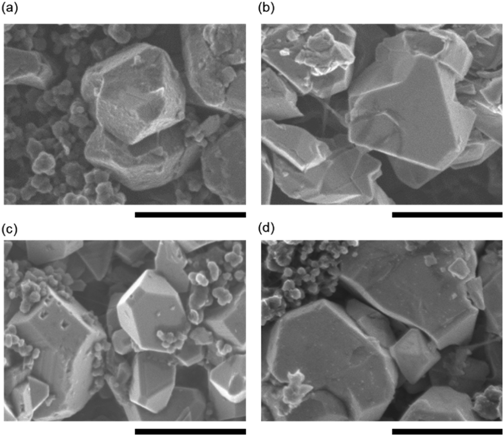 | ||
| Fig. 2 FE-SEM images of the surface of the LNMO cathode (a) LNMO(EC-DMC), (b) FAS-LNMO(EC-DMC), (c) LNMO(EC-DMC/FEC), and (d) FAS-LNMO(EC-DMC/FEC), after 100 cycles. All scale bars are 1.0 μm. | ||
To further understand the qualitative FE-SEM observations, electrochemical impedance spectroscopy (EIS) was performed on the cycled cells. Fig. 3(a) and (b) show the Nyquist plot taken from the half-cells after aging process (0.2C for 3 cycles at room temperature) and taken from the cycled half-cell under a current density of 2C for 100 cycles at 50 °C. Their state of charge was controlled to 100% (fully delithiated state). All the cells present similar profiles, with two capacitive semicircles in the frequency ranges of 200 kHz to 5793 Hz and 5793 to 82 Hz, respectively. The lowest frequencies exhibit linear Warburg impedance, which is derived from the Li+ diffusion within the electrodes. Numerical analysis using the equivalent circuit model displayed in Fig. 3(c) was performed to associate each impedance component. The values of the resistance components are given in Fig. 3(d), in the descending order of their frequency. The initial resistance values of the cells after the aging cycle for CEI formation, between 1.3 and 1.4 Ω, are attributed to the electrolyte; neither the FEC additive nor the FAS layer affects the electrolyte resistance. After 100 cycles, as shown in Fig. 3(b), the electrolyte resistances are barely modified in any of the systems and remain in the same order of magnitude. Therefore, the diffusion of Li ions within the electrolyte is not affected by the addition of high viscosity FEC (2 wt%). After the CEI formation aged via three cycles, the resistance assigned to the CEI layer (RCEI) values of all the systems were found to be in a narrow range of resistance, between 4.5 and 5.2 Ω. Although the FEC additive or FAS grafting does not influence the CEI resistance significantly, it is evident that the LNMO [EC-DMC/FEC] samples have the lowest resistance while the FAS-LNMO [EC-DMC] have the highest. Concerning the charge transfer resistance Rct, the FAS-immobilized LNMO electrodes exhibit slightly higher values than all LNMO electrodes, independent of the addition of FEC to EC-DMC electrolyte. This suggests that the FAS grafting layer behaves as a resistive layer in the early stage of the cycling due to its electron insulating properties. All the systems exhibited higher RCEI values after 100 cycles. The CEI thickness or density is continuously increased during long cycling under harsh temperature conditions. Both LNMO [EC-DMC/FEC] and FAS-LNMO [EC-DMC/FEC] electrodes exhibited significantly lower RCEI in comparison with that of LNMO [EC-DMC], which supports the fact of improved cycling performance. The FAS grafting on the LNMO crystal surface led to the formation of a CEI layer with a resistance (13.0 Ω) close to that of the CEI layer formed on bare LNMO in the presence of the FEC additive (11.9 Ω). Thus, we can expect similar electrochemical behavior for the two systems. Lower RCEI values should either mean that a thinner CEI is formed or that the composition of the CEI has been modified to facilitate higher Li-ion conductivity. Furthermore, trifluoromethylene chain with a helical structured carbon skeleton in FAS molecules possesses a negative dielectric polarization, which attracts Li ions and influences the kinetics of the desolvation process. FAS13 layer having a large polarization with respect to an external electric field might generate an internal electric field along the opposite direction instead of canceling it formed inside of an electric double layer. If the electric field is amplified, it might contribute to accelerate a faster ion change reaction at the electrolyte interface under high C rates. Furthermore, the FAS-LNMO [EC-DMC/FEC] cells exhibited higher RCEI values, close to those of the LNMO [EC-DMC] cells. This may originate from a strong fluorine-mediated intermolecular interaction between the FAS monolayer and FEC molecule, promoting excess CEI layer growth via oxidative decomposition. Furthermore, it suppresses the diffusion of the oxidatively decomposed molecules from the deposited CEI layer on the LNMO surface to the anode surface, which corroborates the observation made from the FE-SEM images of FAS-LNMO [EC-DMC/FEC]. This indicates that a dense and thick CEI layer was formed on the LNMO surface.
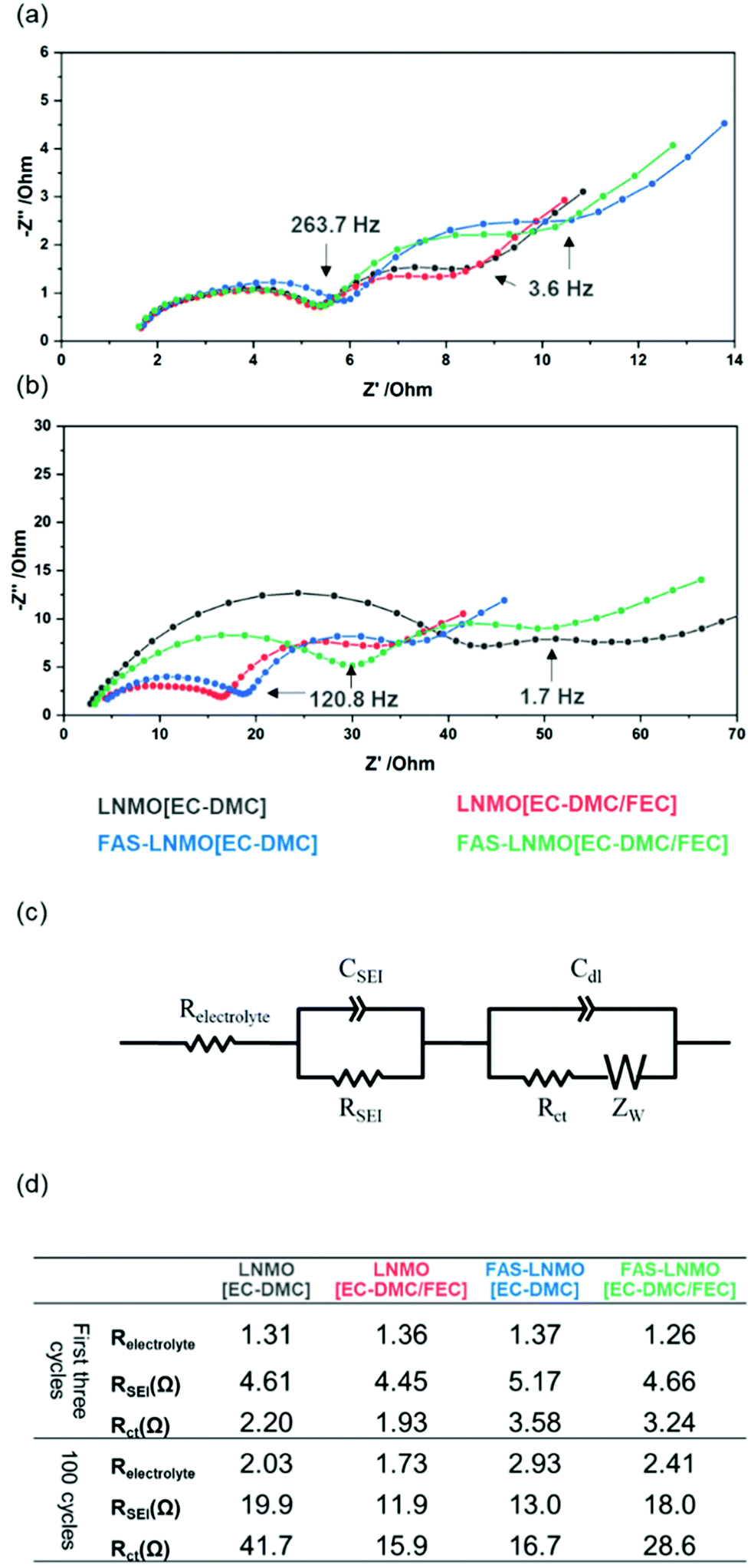 | ||
| Fig. 3 Nyquist plot series of LNMO electrode-based half cells: (a) after first three cycles at 0.2C under room temperature for CEI formation, (b) after 100 cycles at 2C rate under 50 °C, (c) equivalent circuit used for fitting and (d) table of impedance parameters. | ||
The LNMO [EC-DMC] cells exhibited a high RCT value of 41.7 Ω as against 15.9 and 16.7 Ω for LNMO [EC-DMC/FEC] and FAS-LNMO [EC-DMC], respectively. RCT in FAS-LNMO [EC-DMC/FEC] was measured to be 28.6 Ω, which also clearly supports the presence of an interaction between FEC and grafted FAS molecules. Both FE-SEM observations and EIS analysis suggest that the CEI layer formed on the LNMO cathode is influenced by the FAS monolayer like FEC affects the CEI. Moreover, it appears that the FAS monolayer exhibited a selective permeation of specific molecules, behaving like a molecular gate. This might promote effective passage of solvated lithium ions possible and fluorinated molecules, in contrast to the blocking of free solvents and hydrocarbonates.
X-Ray photoemission spectroscopy (XPS) was used to describe, more precisely, the nature of the CEI and identify its constituent species. Indeed, XPS is known to be a powerful analysis technique to investigate the SEI, with several reports available. Fig. 4(a) and (b) display the C1s and P2p core-level high resolution spectra of the LNMO cathode collected after the completion of 100 cycles. The C1s spectrum of the LNMO [EC-DMC] electrode, displayed in black, can be deconvoluted with a component located at 284.6 eV for the aliphatic carbons C–C and the acetylene carbon from the electrode, a component at 285.8 eV for C–O bond environments, 287.0 eV for OCO environments and 289.5 eV for both CH2OCO2Li and species.36 CH2OCO2Li and Li2CO3 are known to be the products of the reactions of both EC and DMC with two electrons and two Li+.37 The noticeable presence of Li2CO3 on the LNMO [EC-DMC] electrodes could contribute to degraded electrochemical performances because of its high resistivity. The CEI appears to be thick on the LNMO electrodes as the CF2–CH2 environment is not detected. The C1s spectrum of FAS-LNMO [EC-DMC] can be deconvoluted using the same components but with a much smaller proportion of Li2CO3. Furthermore, the CF2–CH2 environment from the PVDF is detected, certainly due to a thinner CEI formation, supporting the protective behavior of the FAS monolayer. Since the thinner resistive CEI layer was formed, the electrochemical behavior of FAS-LNMO [EC-DMC] might be superior to that of the LNMO [EC-DMC] system.
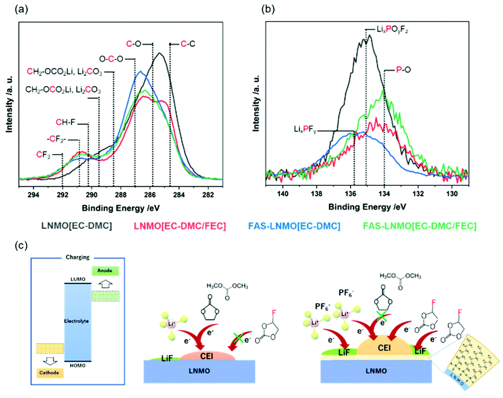 | ||
| Fig. 4 Superimposed LNMO(EC-DMC), FAS-LNMO(EC-DMC), LNMO(EC-DMC/FEC), and FAS-LNMO(EC-DMC/FEC) XPS high resolution spectra after completion of 100 cycles (a) C1s, (b) P2p, and (c) schema summarizing species detected within the CEI layer. | ||
In the case of cells using FEC, FAS-LNMO [EC-DMC], and FAS-LNMO [EC-DMC/FEC], the Li2CO3 species is no longer detected on the LNMO cathode surfaces. Instead, a new component is detected at 290.2 eV in the case of FAS-LNMO [EC-DMC/FEC], which can be attributed to the CH–F environments that may originate from the oxidative decomposition of the FEC additive.38 The FEC˙+ cation is formed by transferring one electron from FEC to the high-voltage LNMO cathode and the DMC˙+ radical cation. Interestingly, this new component was not detected in the systems with LNMO [EC-DMC]. This observation strongly supports our previous hypothesis that the FAS13 monolayer preferentially interacts with the FEC molecules (Fig. 4(c)). Although it is widely accepted that the FEC molecules offer higher stability against oxidative decomposition compared to cyclic and linear carbonates, the significant enhancement in the affinity (wettability) of FEC molecules with the FAS13 monolayer through the negative dielectric polarization of the CF3 groups accelerated their oxidative decomposition at high voltages in association with the modification of the HOMO level of the FEC.
By contrast, when bare LNMO positive electrode is used, FEC is minimally decomposed by oxidation and the CEI layer immediately passivates the LNMO surface. The decomposition of EC and DMC does not dominate excessively with the formation of carbonate species. By comparing the C–O and C![[double bond, length as m-dash]](https://www.rsc.org/images/entities/char_e001.gif) O ratios for all the systems, the following relative ratios are obtained: 30.9%:42.1%, 11.3%:60.7%, 14.7%:60.4%, and 17.7%:55.2% for LNMO [EC-DMC], LNMO [EC-DMC/FAS], FAS-LNMO [EC-DMC], and FAS-LNMO [EC-DMC/FEC], respectively. When a FAS13 monolayer or FEC is present independently at the electrolyte interface, there was a reduction in the formation of polymeric species such as polyethylene oxide (PEO) inside the CEI, compared with that of inorganic carbonates.
O ratios for all the systems, the following relative ratios are obtained: 30.9%:42.1%, 11.3%:60.7%, 14.7%:60.4%, and 17.7%:55.2% for LNMO [EC-DMC], LNMO [EC-DMC/FAS], FAS-LNMO [EC-DMC], and FAS-LNMO [EC-DMC/FEC], respectively. When a FAS13 monolayer or FEC is present independently at the electrolyte interface, there was a reduction in the formation of polymeric species such as polyethylene oxide (PEO) inside the CEI, compared with that of inorganic carbonates.
The XPS P2p core-level spectra exhibit byproducts that originated from the decomposition of LiPF6. The LNMO [EC-DMC] electrode presents a wide and intense P2p signal, which can be deconvoluted with three doublets of components, and only the 2p3/2 binding energies are present. The first one is located at 134.0 eV, corresponding to the P–O environments. They originate from secondary reactions between LiPF6 or PF5 and Li2CO3, or trace amounts of water, which form the intermediate compound POF3 that reacts with R–O–Li to form phosphate species such as OP(OR)3.39 The second and most important component is located at 135.0 eV and is attributed to the fluorophosphate species LixPOyFz, while the third component is located at 135.7 eV and corresponds to LixPFy species. On comparison with bare [STD], a much lower content of degraded salt was observed from the FAS [STD] surface. The proportion of P–O is significantly reduced with a balanced content of both LixPOyFz and LixPFy species. Therefore, the FAS monolayer clearly prevents the degradation of LiPF6 from the LNMO electrode surface in an FEC-free environment. The use of FEC in the electrolyte also suppresses a large LiPF6 degradation but in a less significant way. Moreover, the FEC additive strongly promotes the formation of P–O bonding environments over that of other species.
The EIS measurements and XPS analysis demonstrated the influence of the FAS monolayer on CEI formation by lowering the Li2CO3 content, leading to less impedance growth during the cycles. As described above, the FAS monolayer also exhibits an affinity to the FEC additive, which promotes the continuous oxidative decomposition of FEC molecules in association with consuming several electrons for the CEI formation. The influence of the FAS monolayer on the electrochemical behavior is evaluated in half-cells cycled with cut-off voltages ranging from 3.5 to 4.8 V (vs. Li/Li+) at 2C rate and 50 °C for 200 cycles, as shown in Fig. 5(a). The galvanostatic curves obtained for all the systems in the first charge–discharge reaction are shown in Fig. S4(a) (ESI†). The initial charge/discharge curves show a plateau at 4.7 V vs. Li+/Li derived from Ni3+/Ni4+ and a very small part around 4.0 V vs. Li+/Li originated from Mn3+/Mn4+. The initial charge curves showed a plateau at 4.7 V vs. Li+/Li derived from the sequential oxidation reaction from Ni2+ to Ni3+ and Ni4+. Furthermore, a very small inflexion point observed at around 4.0 V vs. Li+/Li corresponds to the oxidation reaction of Mn3+ to Mn4+. The initial discharge capacities of LNMO [EC-DMC] and FAS-LNMO [EC-DMC] were measured to be up to 135 and 129 mA h g−1, respectively, whereas LNMO [EC-DMC/FEC] and FAS-LNMO [EC-DMC/FEC] exhibited 136 and 131 mA h g−1, respectively. The FAS-modification made the initial capacities lower without depending on the FEC additive, which can be related to the higher initial resistances measured in EIS. Furthermore, the weight increase owing to the immobilization of the self-assembled FAS monolayer lowers the apparent specific capacities due to the increase in the weight of electrodes per unit area. Notably, the first Coulombic efficiency of FAS-LNMO [EC-DMC] was the highest even though the highest capacity was obtained with LNMO [EC-DMC/FEC] cells. This can be explained by the different origins of the excellent oxidation resistance of the FAS monolayer and FEC for the high-voltage LNMO positive electrode. The coulombic efficiencies of the first cycle were 97.9% and 98.1% for LNMO [EC-DMC] and FAS-LNMO [EC-DMC], and 97.9% and 97.9% for LNMO [EC-DMC/FEC] and FAS-LNMO [EC-DMC/FEC]. All the coulombic efficiencies for the first cycle are contained in a narrow range because Li ions are consumed for the CEI and SEI formation in the early cycles in all the systems. The FAS-LNMO [EC-DMC] system mitigates the oxidative decomposition of the electrolyte due to the minimized direct contact area with electrolyte via lower affinity as well as surface stabilization, resulting in an enhanced coulombic efficiency. By contrast, the other cells, including the LNMO [EC-DMC/FEC] cell, exhibited a degradation in the first coulombic efficiency owing to the stable CEI formation via the oxidative decomposition of the electrolyte or FEC. Although it is not desirable to reduce the apparent specific capacity of the electrodes in the FAS-LNMO [EC-DMC] cells due to the increase in the electrode weight from FAS monolayer coating, we believe that improving the initial Coulombic efficiency will contribute to improving cyclability in the full cell system.
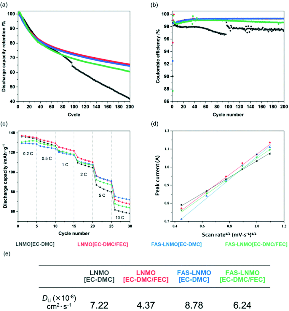 | ||
| Fig. 5 (a) Specific capacity retention over 200 cycles at 1C rate and at 50 °C, (b) corresponding coulombic efficiency over 200 cycles, (c) C-rate tests performed at room temperature, (d) peak current plot vs. voltage sweep rate based on Randles–Sevcik equation, and (e) the corresponding calculated Li ion diffusion coefficient. | ||
After 200 cycles, both LNMO [EC-DMC/FEC] and FAS-LNMO [EC-DMC] cathodes demonstrated the best capacity retention, whereas the LNMO [EC-DMC] cathodes suffered from strong capacity degradation. Interestingly, the electrochemical behaviors of the systems seem to follow the previous observation made from XPS analysis, i.e., the excess CEI layer formation was highly mitigated by the densely grafted FAS monolayer. Fig. 5(b) shows the coulombic efficiencies over 200 cycles at 50 °C. Upon long cycling, LNMO [EC-DMC] exhibited lower and unstable coulombic efficiencies, between 96.5 and 98.5%, whereas the other systems exhibited efficiencies between 99.2 and 98.9% on average for FAS-LNMO [EC-DMC/FEC]. The discharge median voltage, shown in Fig. S4(b) (ESI†), can be used to evaluate the polarization of the cells. LNMO [EC-DMC] cells exhibited a significant deterioration of the discharge median voltage over cycling, with a large drop of 0.11 V after 200 cycles. However, in the case of FAS-LNMO [EC-DMC], the voltage drop after 200 cycles was recorded to be only 0.02 V. Thus, the FAS monolayer effectively mitigates the increase of the cell polarization owing to its reduced Li-ion charge transfer resistance. The FAS-LNMO [EC-DMC/FEC] cells exhibited a lower discharge voltage for the first 40 to 50 cycles; hence, we presume that the CEI formation on the positive electrode surface is not completed and stable until around 50 cycles.
The results of the C-rate tests, between 0.2C and 10C at 25 °C, are shown in Fig. 5(c). At 10C, the FAS-LNMO [EC-DMC] cells provided 55.7% on the 0.2C capacity while only 41.8% of the initial capacity could be recovered at 10C with LNMO [EC-DMC]. LNMO [EC-DMC/FEC] and FAS-LNMO [EC-DMC] exhibited intermediate values of 49.3% and 49.1% respectively. The smaller CEI and charge transfer resistance of the FAS-modified cathode without combination with the FEC additive facilitate better performances at high current density. Moreover, we believe that the grafted FAS molecules could aid the Li-ion desolvation, to provide better high-rate capacity.
To further investigate the kinetic parameters, cyclic voltammetry was systematically conducted at different voltage sweep rates (0.2, 0.4, 0.6, 0.8, 1.0, and 1.2 mV s−1) for all the systems (Fig. S5, ESI†). Fig. 5(d) shows the relationship between the square root of the peak current value, calculated from the Randles–Sevcik equation,40 and the voltage sweep rates for all systems. The slope of the linear fit is the square root of the Li+ diffusion coefficient; therefore, the Li+ diffusion coefficient of the LNMO cathode in each system can be compared qualitatively. As shown in Fig. 5(e), the LNMO [EC-DMC/FEC] cathode exhibited lowest diffusion coefficient while FAS-LNMO [EC-DMC] exhibited the highest. Intermediate slopes are observed for LNMO [EC-DMC] and FAS-LNMO [EC-DMC/FEC], which is in good agreement with the C-rate specific capacities previously described. Based on all results of both cyclability and C rate capability, the FAS monolayer is considered to play the role of preferentially permeating solvated ions rather than uncoordinated solvated molecules. In addition to the negative dielectric polarization effects, the FAS monolayer might also contribute to accelerating the kinetic parameter in the Li+ desolvation step at the LNMO surface via molecular-selective permeation in association with lower activation energy (probably, via splitting its activation barrier). This can be considered a molecular gate effect associated with the drastic change in electrophilic characteristics in the EC-DMC electrolyte solvent solvated to Li ion.
The counter electrode surface has also been studied. High-voltage spinel active materials are known for the dissolution of manganese into the electrolyte, which can be deposited on the anode surface, resulting in a degraded electrochemical behavior.41Fig. 6(a) shows the photographs of Li metal counter electrodes for the four systems studied. A dark deposition is observed on the surfaces of all the Li metal electrodes, indicative of the formation of the SEI. The most significant deposition was observed on the LNMO [EC-DMC] electrode, whereas the FAS-LNMO [EC-DMC] surface exhibited the least deposition, which is in good agreement with the previous electrochemical results.29,30 To evaluate both the dissolution and deposition of Mn and Ni containing compounds on the anode surface, XPS core-level spectroscopy was performed on the separator surface after 100 cycles. The high-resolution spectra of the transition metals are shown in Fig. 6. A comparison of the Mn2p and Ni2p core spectra is shown in Fig. 6(b) and (c). From the binding energies of the peaks, it is evident that Mn does not exist as a metal (2p3/2 binding energy of approximately 638.6 eV) but as a compound such as an oxide or fluoride of a higher oxidation state.42 These Mn compounds formed a resistive layer against Li-ion transport, especially when MnF2 is formed, which affects the electrochemical behavior of the batteries.43 Comparing the peaks of the Ni2p core-level spectra, the peak intensities are clearly weaker in LNMO [EC-DMC/FEC] and FAS-LNMO [EC-DMC]. It is considered that the elution of Ni2+ is highly suppressed owing to the stable and thinner CEI formation. These results also help to explain the improved electrochemical behavior.
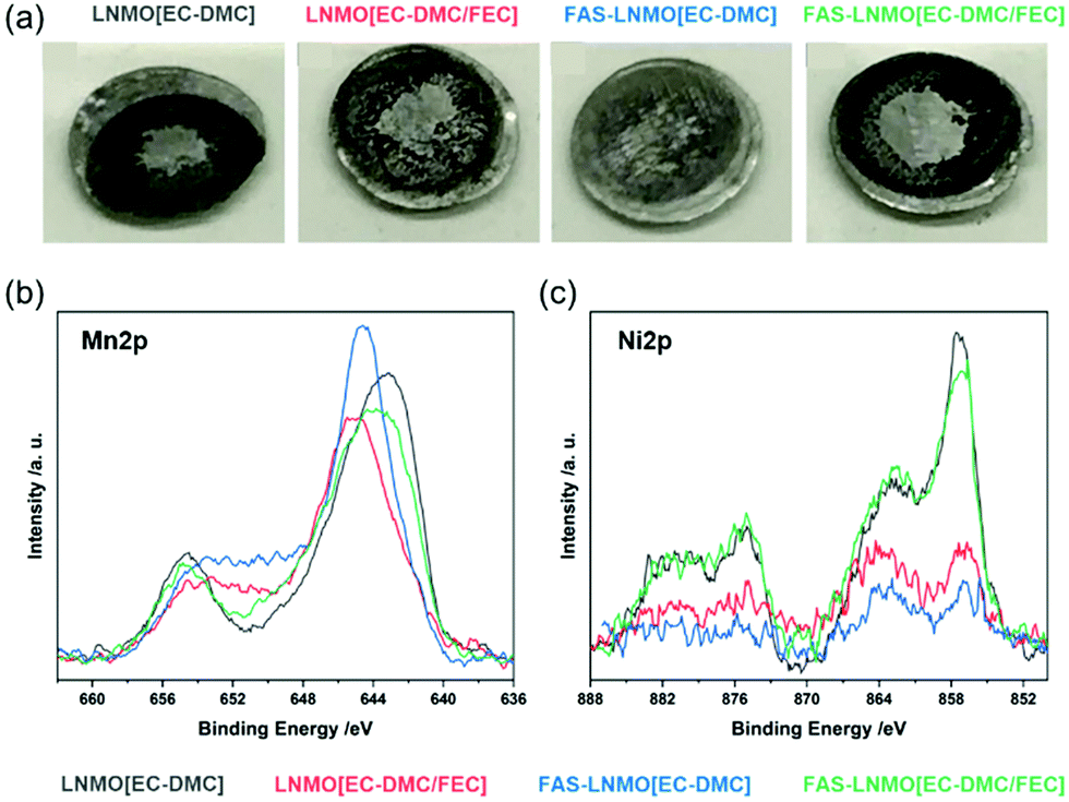 | ||
| Fig. 6 (a) Photograph of the Li metal anode after 200 cycles; (b) XPS core-level spectra of Mn2p and Ni2p recorded on polypropylene separators in each pair of half cells after cycles. | ||
Conclusion
The FAS layer prevented the electrochemical decomposition of carbonate-based electrolytes; however, it enhanced the kinetics of ion exchange reactions at the electrolyte interface including an enhanced C rate capability, a higher ion diffusion constant, and a lower impedance. These facts indicate that the FAS layer is dually working as a protecting layer for preventing the decomposition as well as a mediator for improving the kinetics (lowering activation energy) of the ion exchange reaction at the interface. By contrast, the FAS layer promoted the electrochemical decomposition of electrolyte by adding partially fluorinated linear cyclic carbonates (FEC), as compared to the LNMO bare surface. A small portion of FEC molecules drastically modified the chemical nature of the FAS layer and this resulted in a loss of the protecting function for the decomposition of carbonate-based electrolytes. Furthermore, the Li ion diffusion coefficient evaluations using the Randles–Sevcik equation indicated that the FAS13 monolayer promoted the Li ion exchange reaction at the interface of the FEC-free electrolyte. This trend implies that highly ordered helical –(CF2)6– chains with CF3 groups at the molecular ends perform the function of a molecular gate. It offered selective permeation of solvated-Li ions as well as fluorinated ether which accelerates the kinetic parameter in the desolvation step by splitting its activation barrier. The advantages of FAS coating to the LNMO electrode were similar to those obtained using the FEC additive to bare LNMO electrodes; however, the molecular gate effects in the FAS13 monolayer immobilized on the LNMO surface created an important advantage in its first coulombic efficiency over that of the FEC additives. We believe that the introduction of highly designed molecular systems onto the electrode surface could potentially provide multi-functions that are difficult to achieve with conventional additive technology.Author contributions
Y. C. and H. T contributed to the preparation and electrochemical analysis of the electrodes and cells. Y. C., H. T. and N. Z. contributed to the drafting of this paper. N. Z. contributed to the concept and design of this study. K. T. contributed to managing this project.Conflicts of interest
There are no conflicts to declare.Acknowledgements
This work was partially supported by the MEXT Regional Innovation Ecosystems Program. N. Z. and Y. C. acknowledge the NEDO programs.Notes and references
- K. Mizushima, P. C. Jones, P. J. Wiseman and J. B. Goodenough, Mater. Res. Bull., 1980, 15, 783–789 CrossRef CAS.
- M. M. Thackeray, W. I. F. David, P. G. Bruce and J. B. Goodenough, Mater. Res. Bull., 1983, 18, 461–472 CrossRef CAS.
- A. Manthiram and J. B. Goodenough, J. Solid State Chem., 1987, 71, 349–360 CrossRef CAS.
- A. Manthiram and J. B. Goodenough, J. Power Sources, 1989, 26, 403–408 CrossRef CAS.
- A. K. Padhi, J. Electrochem. Soc., 1997, 144, 1188 CrossRef CAS.
- J. M. Tarascon and B. Guyomard, J. Electrochem. Soc., 1991, 138, 2864 CrossRef CAS.
- A. Du Pasquier, J. Electrochem. Soc., 1999, 146, 428 CrossRef CAS.
- R. J. Gummow, A. de Kock and M. M. Thackeray, Solid State Ionics, 1994, 69, 59–67 CrossRef CAS.
- C. Zhan, J. Lu, A. Jeremy Kropf, T. Wu, A. N. Jansen, Y. K. Sun, X. Qiu and K. Amine, Nat. Commun., 2013, 4, 1–8 Search PubMed.
- Q. Zhong, B. Arman, Z. Meijie, G. Yuan and J. R. Dahn, J. Electrochem. Soc., 1997, 144, 205 CrossRef CAS.
- R. Santhanam and B. Rambabu, J. Power Sources, 2010, 195, 5442–5451 CrossRef CAS.
- J. H. Kim, S. T. Myung, C. S. Yoon, S. G. Kang and Y. K. Sun, Chem. Mater., 2004, 16, 906–914 CrossRef CAS.
- S. Zhou, T. Mei, X. Wang and Y. Qian, Nanoscale, 2018, 10, 17435–17455 RSC.
- C. Gao, H. Liu, S. Bi, H. Li and C. Ma, Green Energy Environ., 2021, 6(1), 114–123 CrossRef.
- L. Wang, G. Liu, W. Wu, D. Chen and G. Liang, J. Mater. Chem. A, 2015, 3, 19497–19506 RSC.
- W. Sun, Y. Li, Y. Liu, Q. Guo, S. Luo, J. Yang, C. Zheng and K. Xie, J. Mater. Chem. A, 2018, 6, 14155–14161 RSC.
- J. Yoon, M. Jeong, I. T. Bae, K. W. Nam and W. S. Yoon, J. Power Sources, 2017, 368, 1–10 CrossRef CAS.
- P. Sun, Y. Ma, T. Zhai and H. Li, Electrochim. Acta, 2016, 191, 237–246 CrossRef CAS.
- H. Shiiba, N. Zettsu, S. Kida, D.-W. Kim and K. Teshima, J. Mater. Chem. A, 2018, 6, 22749–22757 RSC.
- D.-W. Kim, H. Shiiba, N. Zettsu, T. Yamada, T. Kimijima, G. Sánchez-Santolino, R. Ishikawa, Y. Ikuhara and K. Teshima, NPG Asia Mater., 2017, 9, e398 CrossRef CAS.
- D.-W. Kim, N. Zettsu, H. Shiiba, G. Sánchez-Santolino, R. Ishikawa, Y. Ikuhara and K. Teshima, J. Mater. Chem. A, 2020, 8, 22302–22314 RSC.
- H. Kageyama, K. Hayashi, K. Maeda, J. P. Attfield, Z. Hiroi, J. M. Rondinelli and K. R. Poeppelmeier, Nat. Commun., 2018, 9, 772 CrossRef PubMed.
- W. K. Shin, Y. S. Lee and D. W. Kim, J. Mater. Chem. A, 2014, 2, 6863–6869 RSC.
- H. Wang, L. Ben, H. Yu, Y. Chen, X. Yang and X. Huang, J. Mater. Chem. A, 2017, 5, 822–834 RSC.
- J. Mou, Y. Deng, L. He, Q. Zheng, N. Jiang and D. Lin, Electrochim. Acta, 2018, 260, 101–111 CrossRef CAS.
- T. Qiu, J. Wang, Y. Lu and W. Yang, Electrochim. Acta, 2014, 147, 626–635 CrossRef CAS.
- H. Deng, P. Nie, H. Luo, Y. Zhang, J. Wang and X. Zhang, J. Mater. Chem. A, 2014, 2, 18256–18262 RSC.
- R. Zhu, S. Zhang, Q. Guo, Y. Zhou, J. Li, P. Wang and Z. Gong, Electrochim. Acta, 2020, 342, 136074 CrossRef CAS.
- N. Zettsu, S. Kida, S. Uchida and K. Teshima, Sci. Rep., 2016, 6, 1–8 CrossRef.
- D.-W. Kim, S. Uchida, H. Shiiba, N. Zettsu and K. Teshima, Sci. Rep., 2018, 8, 1–9 CrossRef.
- S. Shibuichi, T. Yamamoto, T. Onda and K. Tsujii, J. Colloid Interface Sci., 1998, 208, 287–294 CrossRef CAS.
- T. Shimoda, S. Miyashita, O. Takai and H. Sugimura, JP 3879312, 2007.
- H. B. Son, M.-Y. Jeong, J.-G. Han, K. Kim, K. H. Kim, K.-M. Jeong and N.-S. Choi, J. Power Sources, 2017, 368, 1–10 CrossRef.
- D. Aurbach, J. Power Sources, 2000, 89, 206–218 CrossRef CAS.
- J. Kim, N. Go, H. Kang, A. Tron and J. Mun, J. Electrochem. Sci. Technol., 2017, 8, 53–60 CrossRef CAS.
- P. Verma, P. Maire and P. Novák, Electrochim. Acta, 2010, 55, 6332–6341 CrossRef CAS.
- H. Yoshida, T. Fukunaga, T. Hazama, M. Terasaki, M. Mizutani and M. Yamachi, J. Power Sources, 1997, 68, 311–315 CrossRef CAS.
- G. M. Veith, M. Doucet, R. L. Sacci, B. Vacaliuc, J. K. Baldwin and J. F. Browning, Sci. Rep., 2017, 7, 1–15 CrossRef CAS PubMed.
- S. Laruelle, S. Pilard, P. Guenot, S. Grugeon and J.-M. Tarascon, J. Electrochem. Soc., 2004, 151, A1202 CrossRef CAS.
- P. Zanello, Voltammetric Techniques – Inorganic Electrochemistry: Theory, Practice and Application, 2003 Search PubMed.
- A. Bhandari and J. Bhattacharya, J. Electrochem. Soc., 2017, 164, A106–A127 CrossRef CAS.
- M. C. Biesinger, B. P. Payne, A. P. Grosvenor, L. W. M. Lau, A. R. Gerson and R. S. C. Smart, Appl. Surf. Sci., 2011, 257, 2717–2730 CrossRef CAS.
- J. B. Gieu, V. Winkler, C. Courrèges, L. El Ouatani, C. Tessier and H. Martinez, J. Mater. Chem. A, 2017, 5, 15315–15325 RSC.
Footnote |
| † Electronic supplementary information (ESI) available. See DOI: 10.1039/d1ma00426c |
| This journal is © The Royal Society of Chemistry 2021 |