
 Open Access Article
 This Open Access Article is licensed under a Creative Commons Attribution-Non Commercial 3.0 Unported Licence
Sulfur promotes hydrogen evolution on molybdenum carbide catalysts†
Ju Ye
Kim
 abcd,
Per
Lindgren
a,
Yin-Jia
Zhang
e,
Seok Ki
Kim
d,
Thomas M.
Valentin
a,
Hee-Tae
Jung
bc and
Andrew A.
Peterson
*a
abcd,
Per
Lindgren
a,
Yin-Jia
Zhang
e,
Seok Ki
Kim
d,
Thomas M.
Valentin
a,
Hee-Tae
Jung
bc and
Andrew A.
Peterson
*a
aSchool of Engineering, Brown University, Providence, Rhode Island 02912, USA. E-mail: andrew_peterson@brown.edu
bDepartment of Chemical and Biomolecular Engineering, Korea Advanced Institute of Science and Technology (KAIST), Daejeon, 34141, South Korea
cKAIST Institute for the NanoCentury, KAIST, 291 Daehak-ro, Yuseong-gu, Daejeon 34141, Republic of Korea
dCarbon Resources Institute, Korea Research Institute of Chemical Technology, 141 Gajeongro, Yuseong, Daejeon, Korea
eDepartment of Chemistry, Brown University, Providence, Rhode Island 02912, USA
First published on 30th June 2021
Abstract
We report the synthesis of sulfur-doped molybdenum carbide (Mo2C) catalysts with high activity towards electrochemical hydrogen evolution and excellent stability under acidic conditions. We show that sulfur – a well-known catalyst poison – acts as a promoter by weakening the hydrogen binding energy of Mo2C, which is generally considered to bind hydrogen too strongly. Physical and chemical characterizations of sulfur-doped Mo2C catalysts suggest that sulfur is successfully doped into the Mo2C crystal lattice. We found the optimal sulfur loading to be around 7 wt%, which required −92 mV overpotential for −10 mA cm−2 with Tafel slope value of 51 mV dec−1. In our analysis, the sulfur atoms in the lattice occupied the original hydrogen adsorption sites in the Mo2C lattice. This weakens the hydrogen binding energy, to which we attribute the higher activity towards hydrogen evolution.
Introduction
Hydrogen is a promising energy carrier because of its high energy density and usefulness in renewable energy processes, such as fuel cell technologies.1–3 A scalable hydrogen economy is dependent upon the development of efficient and inexpensive cathode materials for the hydrogen evolution reaction (HER)—the cathodic reaction of water electrolysis. Platinum (Pt) is the best HER catalyst discovered to date, with extremely low onset potential and excellent current response with applied potential (Tafel slope). However, the high cost and low abundance of Pt hinder large-scale implementation. Therefore, the development of inexpensive and earth-abundant electrocatalysts with high activity and stability under scale-up process conditions is a critical issue that addresses future energy demands and environmental problems.1–3 To date, transition metal compounds are considered some of the most promising HER catalysts because of their low cost, earth-abundance and relatively high activity towards hydrogen evolution.2–7 Among them, molybdenum carbide (MoxC) materials have garnered attention because of their good electrical conductivity, Pt-like d-band electronic structure properties,8 chemical stability6,9 and high catalytic activity towards hydrogen evolution.Previous work10,11 has concluded that the presence of adsorbates such as OH or CO on certain molybdenum-based catalysts can increase the catalysts’ activity for hydrogen evolution. This is perhaps surprising since these adsorbates would be expected to interfere with (that is, poison) available active sites; however, the increase in activity has been attributed to a weakening of the surface–hydrogen bond, making the surface more active for hydrogen evolution. Since the site-blocking effect is fractional while the binding-energy effect is exponential, the exponential effect dominates and the net result is improved activity. These coverage effects are prominent especially for Mo2C among various transition metal carbides (TMCs).7,12 Outside of the hydrogen evolution reaction, many reports have shown enhanced catalytic effects via CO poisoning. For instance, gold surfaces that are pre-occupied with adsorbed CO can provide advantageous OH adsorption sites leading the oxidation of CO in solution13 and can be a preferable alcohol oxidation sites by promoting C–H bond breaking.14
However, the transient nature of these co-adsorbates (they can easily undergo proton-coupled electron transfer or surface coupling reactions) means that they can readily leave the surface. Thus, we require a more permanent co-adsorbate that can enhance the HER activity of Mo2C by weakening the hydrogen binding energy.
Sulfur (S) is an obvious choice for this role, as it is well-known to be a recalcitrant catalyst poison.15 Here, we hypothesized that the presence of sulfur on Mo2C would result in a catalyst with both high activity and long-term stability. We performed electronic structure calculations to understand how sulfur coverage affects the hydrogen binding energy of Mo2C. The computational results suggest that the presence of sulfur significantly affects the hydrogen binding energy, and monotonically weakens it as the coverage increases, as shown in Fig. 1. Computational details are included in the ESI.†
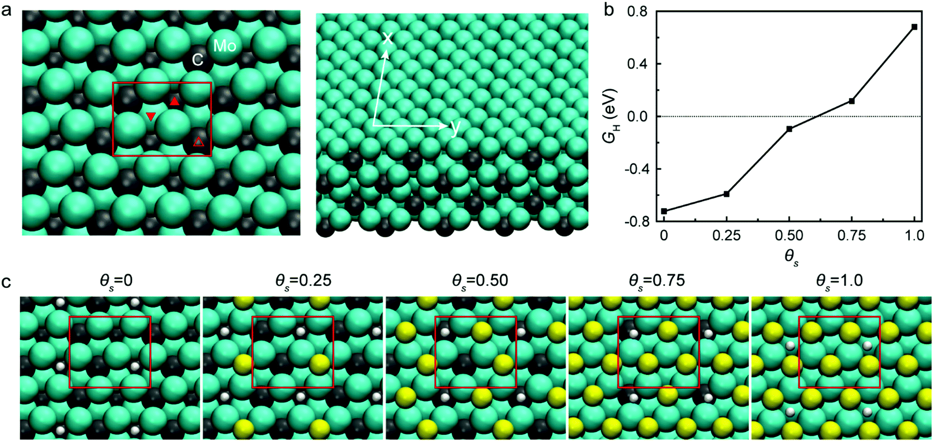 | ||
| Fig. 1 Hydrogen binding energy calculations and related illustrations for various sulfur coverages. (a) Mo2C system and its three distinct hollow sites: subsurface interstitial (filled up), subsurface carbon (open up), and subsurface molybdenum (filled down). (b) Hydrogen binding energy on bare Mo2C and Mo2C with varying sulfur coverages. (c) Favorable hydrogen adsorption sites on sulfur doped Mo2C depending on sulfur coverages: θS = 0.25, θS = 0.50, θS = 0.75, and θS = 1.0. | ||
Motivated by these insights, we synthesized sulfur-doped Mo2C catalysts with varying sulfur concentrations and performed electrocatalytic tests. So far, there are a few studies using sulfur-containing molybdenum carbide. MoS2-decorated molybdenum carbides (MoSx@Mo2C) were fabricated for hydrogen evolution,16 but sulfur was just used for fabricating MoSx. Nitrogen and sulfur co-doped Mo2C nanosheets have also been reported,17 but the study focused on wetting effects rather than changes in the intrinsic properties of the catalyst. Due to the lack of knowledge about sulfur in Mo2C, here we developed a method to synthesize sulfur-doped Mo2C catalysts with optimal sulfur doping concentration conditions for high activity, and then demonstrated how doped sulfur affects the intrinsic catalytic activity of Mo2C.
As we will show, the synthesized catalysts are more intricate than what was initially assumed in the computational work; the sulfur does not adsorb onto the surface, but rather integrates within the Mo2C lattice. Electrochemical tests reveal significantly enhanced HER performance with −92 mV overpotential at −10 mA cm−2 and excellent stability. Our catalysts perform as well or better than the most-active Mo2C preparations reported to date, which all rely on intricate support interactions or sophisticated hierarchical structures.5,18–20 As we will further show, as the concentration of sulfur increases, the HER activity improves until the excess sulfur segregates as MoS2 islands on the catalyst surface. In other words, a Mo2C/MoS2 composite catalyst showed inferior performance compared to doped Mo2C with intermediate sulfur loading. We believe these findings can contribute to the understanding of doping effects on the catalytic property of Mo2C towards hydrogen evolution.
Results and discussion
Physical characterization
To understand the influence of sulfur on HER, we designed sulfur-doped Mo2C with varying sulfur concentrations (Fig. S1, ESI†); Fig. 2 shows the composition and morphology of our synthesized electrocatalysts. The exact sulfur amounts in the synthesized samples were further analyzed by using inductively coupled plasma atomic emission spectroscopy (ICP-AES, Table S1, ESI†) to be 1.1, 7.2, and 11.1 wt%; we will refer to these sulfur-doped Mo2C catalysts as S(1), S(7), and S(11), respectively.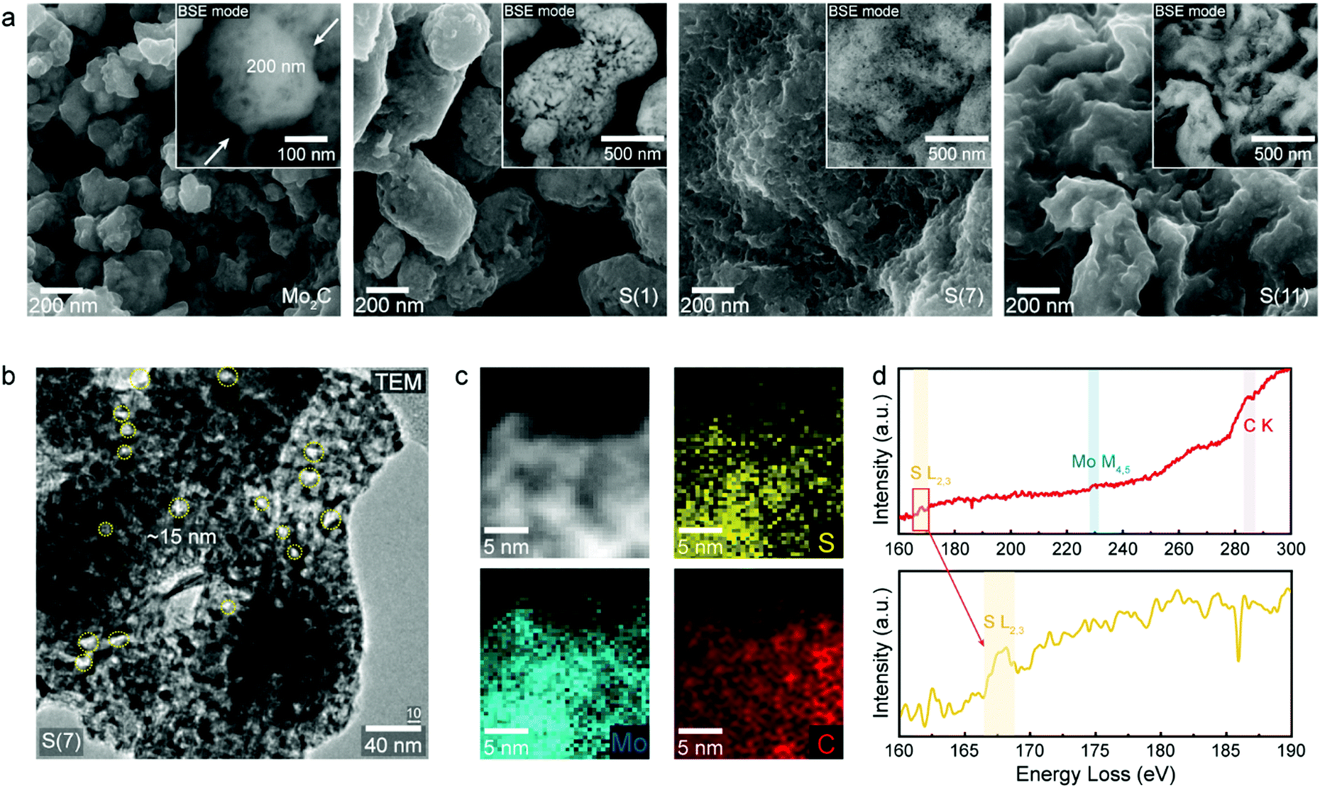 | ||
| Fig. 2 Characterization observations of as-synthesized sulfur doped molybdenum carbides. (a) Morphology investigation with scanning electron microscopy (SEM) depending on sulfur doping concentrations: Mo2C, S(1), S(7) and S(11). (b) Transmission electron microscopy (TEM) image of S(7) to demonstrate porous morphology and pore size. (c) Electron energy loss spectroscopy (EELS) mapping image of S(7) and (d) element spectrum of fabricated sulfur doped Mo2C. | ||
The morphology of our electrocatalysts are shown in Fig. 2a and b using scanning electron microscope (SEM) with back-scatter detector (BSE) mode and high-resolution trans mission electron microscopy (HR-TEM). The Mo2C and sulfur-doped Mo2C were fabricated with a porous structure after the carburization process, since the urea is thermally decomposed in high temperature of carburization process.21 As sulfur concentrations increased, the bulk structures changed from nanoparticles to sheets (Fig. 2a). (An additional low magnification image of S(7) was represented in Fig. S2, ESI.†) The normal molybdenum carbide without sulfur doping shows a particle shape of 200 nm diameter whereas S(1) forms larger nanoparticle morphologies of around 500 nm diameter. When the sulfur concentration increases, the nanoparticle morphology starts to be destroyed, resulting in connected sheets instead as seen for of S(7) and S(11).
Surface area and pore size of synthesized materials were observed by the Brunauer–Emmett–Teller (BET) and Barrett–Joyner–Halenda (BJH) methods, respectively, and related data are shown in Fig. S3 and Table S2 of the ESI.† We observed that the surface area decreased as the sulfur loading increased, which we attribute to the morphology differences discussed above.
Fig. 2b shows a transmission electron microscopy (TEM) image of S(7). The morphology again shows a sheet structure, as observed in SEM (Fig. 2a), and pore size dimensions are well matched with BJH analysis having 17 nm pore size (Table S2, ESI†). To observe elemental distributions within fabricated catalysts further characterization was conducted. Since molybdenum (Mo) and sulfur (S) elements have small energy differences (14 eV) by energy dispersive X-ray spectroscopy (EDS), it is hard to distinguish Mo and S elements with the energy resolution in EDS (130–150 eV). Instead, electron energy loss spectroscopy (EELS) analysis was carried out by cs-corrected Titan TEM. The sulfur (S), molybdenum (Mo) and carbon (C) atoms were distributed uniformly according to the EELS mapping observations in Fig. 2c. Fig. 2d shows EEL spectra of each elements indicating the existence of S, Mo and C contents in S(7) from the S L2,3 (167 eV), Mo M4,5 (228.5 eV) and C K (285 eV) signals, respectively.22,23
Chemical structure analysis depending on sulfur concentrations
Fig. 3 contains crystal structure analysis of fabricated molybdenum carbides and related observations depending on sulfur doping concentrations. To characterize the crystal structure, high resolution transmission electron microscopy (HR-TEM) and lattice fringe analysis were performed as shown in Fig. 3a. The distances between lattice fringes were measured by averaging 10 or more distances. D-Spacing values of S(7) were 0.224 nm and 0.239 nm with an angular of 61.5°, which correspond to (211) and (020) lattice planes of orthorhombic phase of Mo2C, respectively (the detailed calculations of d-spacing and angle are explained in the ESI†). Thus, intermediate sulfur loadings (7 wt%) can be successfully inserted into the molybdenum carbide without destroying the crystalline structure whereas higher sulfur loadings (11 wt%) start to generate MoS2 islands; starting from the S(11), we could clearly observe MoS2 formation on the surface (Fig. S4, ESI†). This indicates that the excess sulfur easily aggregates on the Mo2C surface. For comparison, the characterizations for the Mo2C (non-sulfur doped porous Mo2C) were represented in Fig. S5 (ESI†).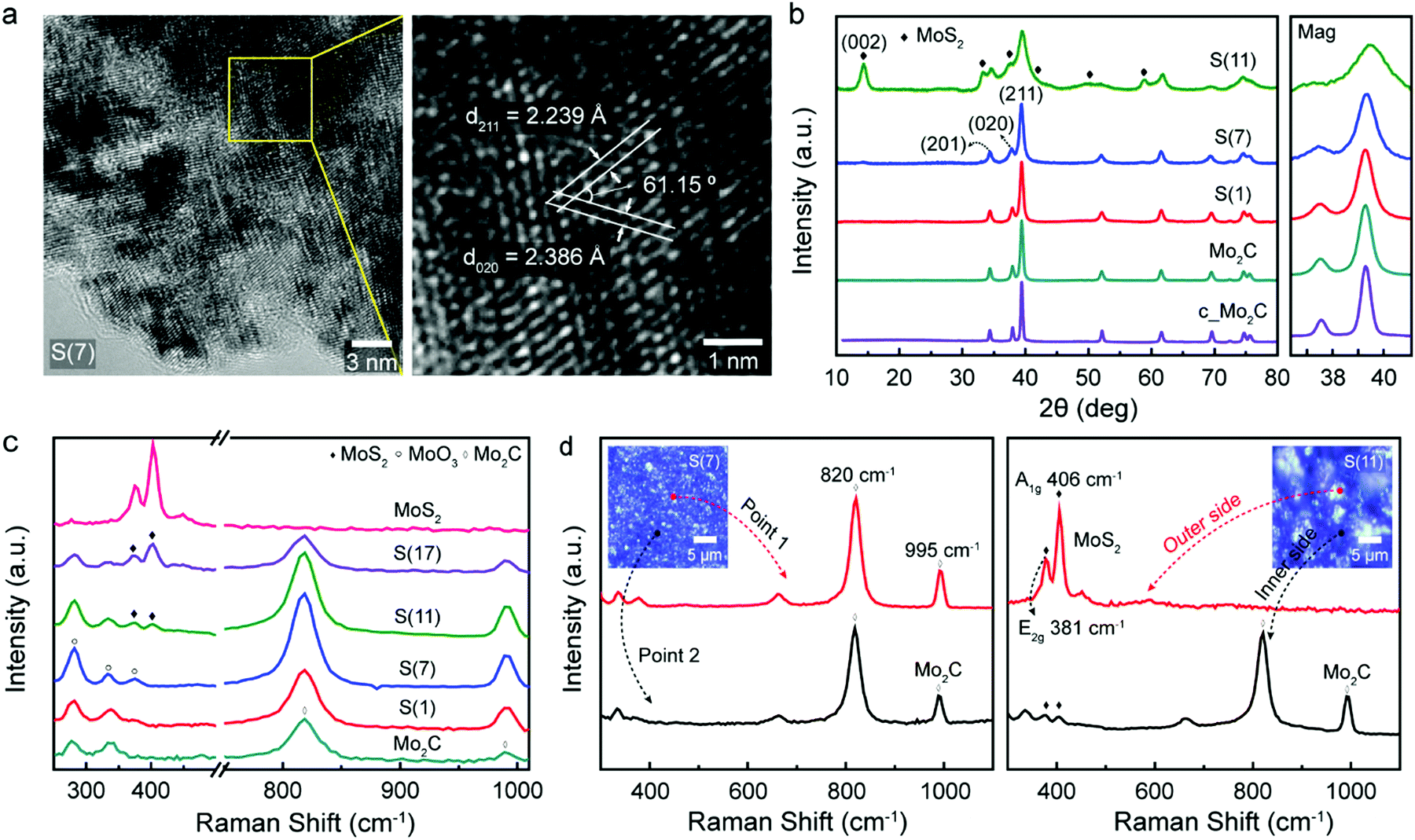 | ||
| Fig. 3 Crystal structure analysis of synthesized molybdenum carbides. (a) High resolution transmission electron microscopy (HR-TEM) analysis of S(7), and related lattice fringe measurements. (b) X-Ray diffraction (XRD) peaks of fabricated samples: Mo2C, S(1), S(7), and S(11). The magnified XRD peak around 39° is on the right. (c) Raman spectra of as-synthesized molybdenum carbide, sulfur doped molybdenum carbide on various concentrations, and molybdenum disulfide. (d) Raman spectra of S(7) and S(11) in the range of 300–1100 cm−1. | ||
These observations are also match with X-ray diffraction (XRD) experiments in Fig. 3b. All diffraction peaks of synthesized samples were consistent with a reference (PDF No. 01-077-0720, β-Mo2C)9,24 while higher sulfur loadings Mo2C (11 wt%) has additional MoS2 crystalline phase patterns (PDF No. 00-024-0513),25 which come from the MoS2 formation by excess sulfur. For Mo2C, the obtained diffraction peaks are 34.3°, 37.9°, and 39.3° which are attributed to the (201), (020), and (211) planes of Mo2C. The crystallinity of Mo2C slightly decreased as sulfur doping (see the magnified XRD graphs in Fig. 3b), which indicates the successful sulfur doping into Mo2C lattice.26 In addition to Mo2C diffraction peaks, in the case of S(11) a strong peak at 14.3° indicates the (002) lattice plane of molybdenum disulfide. This agrees with the TEM analysis discussed above. Raman observations further confirm that the synthesized Mo2C has both Raman spectra peaks at 820 cm−1 and 995 cm−1 (Fig. 3c), which are typical two Mo2C peaks.27 The small typical in-plane E2g (381 cm−1) and out-of-plane A1g (406 cm−1) peaks of MoS228 starts to show in higher sulfur-doped catalysts (over 11 wt%), from the formation of MoS2.
As shown in Fig. 3d, S(7) has a uniform, bulk morphology and contains the typical Mo2C Raman spectrum everywhere. Especially, the disappearance of typical sulfur peaks (153, 218, and 474 cm−1)29 indicates the successful dispersion of sulfur in Mo2C crystal structure (Fig. S6, ESI†). On the other hand, for higher sulfur-loading Mo2C, S(11), the aggregated bulk MoS2 islands begins to form on the surface (Fig. S7, ESI†) since the limitation of sulfur-doping has been reached. The island shows only the MoS2 Raman spectrum without Mo2C Raman peaks (Fig. 3d, the red-line on the right graph for S(11)). On the inner side under MoS2 island, however, both Mo2C and tiny MoS2 Raman spectrum peaks were observed (Fig. 3d, black-line on the right graph for S(11)). That is, higher sulfur loadings showed morphologies consistent with a mixture of MoS2 and Mo2C while lower sulfur loadings had uniform Mo2C in overall areas as shown in Fig. 3d (left graph for S(7)). Overall, it is clearly demonstrated that for the lower sulfur concentrations, the sulfur was successfully inserted into the Mo2C crystal structure.
Sulfur position in the Mo2C structure
To investigate how doped sulfur exists in the molybdenum carbide structures, we conducted X-ray photoelectron spectroscopy (XPS) measurements. In Fig. 4, the obtained XPS spectra of C 1s and S 2p were represented by calibrating based on the C–C peak, 284.7 eV.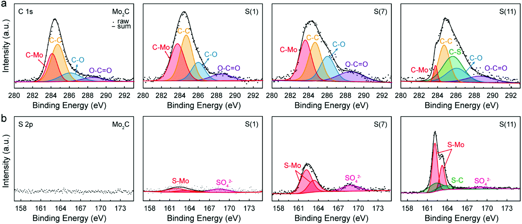 | ||
| Fig. 4 X-Ray photoelectron spectroscopy (XPS) observations with fabricated catalysts. (a) C 1s spectra and (b) S 2p spectra of Mo2C, S(1), S(7), and S(11). | ||
For C 1s photoelectron analysis (Fig. 4a), the binding energy of deconvoluted peaks were 283.64, 284.7, 286.06, and 288.58 eV, corresponding to C–Mo, C–C, C–O, and O–C–O, respectively (Table S3, ESI†).30–32 Due to the sulfur dopings, the C–Mo binding energy was down-shifted to 283.64 eV, while non-sulfur doped Mo2C had 284.11 eV in this study. For intermediate sulfur loadings (≤7 wt%) there are no C–S peaks in both C 1s and S 2p spectrums, indicating that sulfur has replaced carbon. In contrast, for higher sulfur loadings (≥11 wt%) the excess sulfur started to bind with carbon, forming C–S bonds as shown in both C 1s (C–S peak, 1s 285.67 eV) and S 2p spectra (S–C double peaks, 2p3/2 162.23 and 2p1/2 163.53 eV.33,34); in the presence of excessive sulfur, S starts to be used to form MoS2 resulting in a Mo2C/MoS2 composite when the limit of sulfur replacement of carbon site is reached. For S(11), the formation of MoS2 is assigned to a typical S 2p spectrum of MoS2 (Fig. 4b).31 In addition, the newly formed MoS2 leads to a reduction in the C–Mo peak intensity under the same Mo salt (see the Fig. 4a).
The high-resolution spectrum of S 2p has three main peaks at 162.13, 163.23, and 168.7 eV which can be assigned35–38 to 2p3/2, 2p1/2, and SO42− demonstrating the sulfur in Mo2C; as sulfur replaces the carbon site, Mo–S bonds generate instead of Mo–C bonds. Thus, by XPS observations we can confirm that intermediate sulfur loadings (≤7 wt%) lead to successful insertion of S into Mo2C corresponding to the HR-TEM and XRD results. Consistent with our previous findings, in Fig. 4b the S–C peaks at 162.23 and 163.53 eV were evident only for higher sulfur loadings Mo2C (≥11 wt%).
For intermediate sulfur loadings Mo2C (especially for 7 wt%), sulfur atoms are well integrated in the Mo2C crystal structure and create a “long-lasting poison”, which decreases the hydrogen adsorption energy. In contrast, higher sulfur loadings facilitate agglomeration of MoS2 islands on the catalyst, whose HER activity is apparently lower than that of sulfur doped Mo2C (see the polarization curve in Fig. 5a).
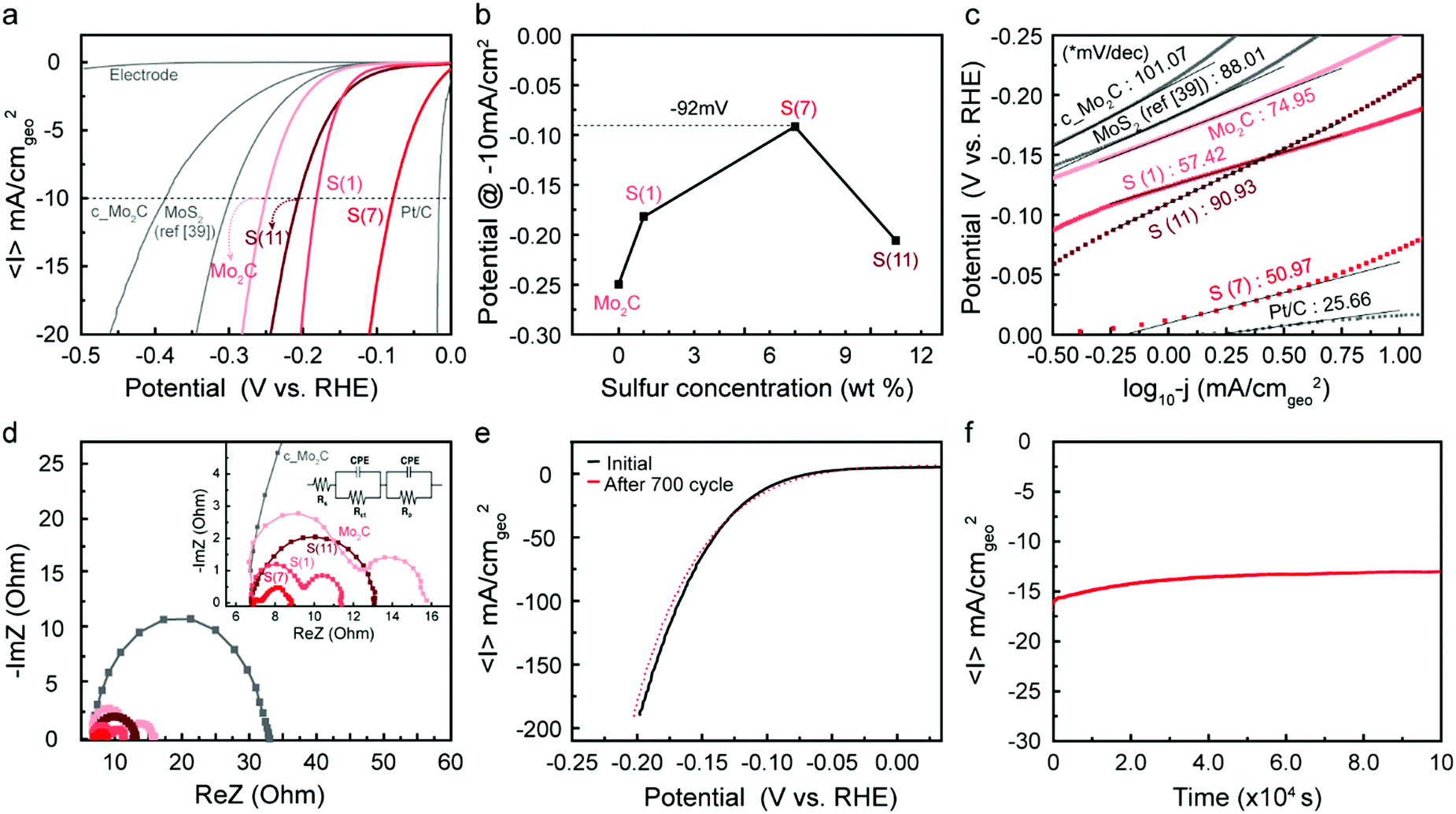 | ||
| Fig. 5 Electrochemical characteristics of synthesized catalysts. (a) Polarization curves (linear sweep voltammetry test, LSV) of hydrogen evolution reaction (HER) and (b) corresponding potential plot depending on sulfur loadings at −10 mA cmgeo−2. The scan rate was 10 mV s−1 and the catalyst loading was 0.0294 mg cmgeo−2. (c) Tafel slopes of MoS2, c_Mo2C, fabricated Mo2C, S(1), S(7), S(11) and Pt/C. (d) Potentiostatic electrochemical impedance spectroscopy (PEIS) test at −0.4 V (vs. RHE) ranging from 1 MHz to 0.5 Hz and corresponding fitted plots. The inset shows related equivalent circuit model. (e) Durability test of S(7) at a range from 0.05 V to −0.2 V. (f) Long-term stability test at −0.8 V (vs. RHE) for 28 hours. All the experiments were operated by using 0.5 M H2SO4 electrolyte under Ar environment. Current densities were divided by geometric area. | ||
Electrocatalytic performance
Fig. 5 shows electrochemical testing of these synthesized catalysts, as well as comparisons to reference samples. Fig. 5a shows linear sweep voltammetry normalized per geometric surface area of the electrode, where we mark the current at −10 mA cm−2 as a point to compare overpotentials between catalysts. First, we note that our synthesized molybdenum carbide nanoparticles (denoted as Mo2C) showed higher current densities than commercial samples (purchased from Sigma-Aldrich and denoted as c_Mo2C); this is attributed to the increased surface area due to the nanoparticle shape and porosity characteristics. When sulfur is doped into the Mo2C catalysts, we see an increase in catalytic activity, resulting in a significant decrease in the overpotential depending on the sulfur doping level (see the Fig. 5b). The overpotential decreased with increased sulfur loadings, to as low as −92 mV at 7 wt% S, then increased as the loading was further raised to 11 wt%.The decreased activity at 11 wt% correlates with the observed formation of MoS2 islands, as discussed in the characterization section. After an optimum amount of sulfur is inserted into Mo2C, the sulfur forms MoS2 islands on the catalyst, leading to decreased electrocatalytic activity compared to the sulfur-doped Mo2C catalyst. The improved HER performance was maximized when considering the real surface area (based on BET) and estimated electrochemical surface area (ECSA) from double-layer capacitance (Cdl) (Fig. S8–S10, ESI†), supporting the enhancement of intrinsic activity via sulfur doping.
To provide standard points of comparison, a Pt/C catalyst and a commercial MoS2 (Sigma-Aldrich, 99%) were also tested under identical electrocatalysis conditions. The MoS2 has similar dimensions (particle size ∼2 μm) with that of a published study39 and was tested under the same catalyst preparation conditions; that is, unlike our Mo2C samples, we did not use Nafion as a binder, so ref. 39 was reproduced identically. The sample was noted as MoS2 (ref. 39). The purchased standard catalysts resulted in similar behavior with previous reports6,39 indicating the reliability of our system.
Tafel slopes were generated to investigate the current response to the applied potential (Fig. 5c). Since Tafel slopes are inverse measures of current response with respect to applied potential, a low Tafel slope indicates a good kinetic response. The S(7) catalyst has both a low onset potential as well as a low Tafel slope of 51 mV dec−1. In addition to this, the Tafel plot is often used to predict the rate-determining step and possible reaction mechanism for the HER. In acidic conditions, three steps are typically considered for HER. After a proton adsorbs on the catalyst surface at the initial stage (Volmer step, 120 mV dec−1, primary discharge, H+ + e− → Hads), (1) an adsorbed hydrogen atom reacts with a proton and an electron (Heyrovsky step, 40 mV dec−1, electrochemical desorption, Hads + H+ + e− → H2) or (2) two adsorbed hydrogen atoms react, generating H2 (Tafel step, 30 mV dec−1, recombination, Hads + Hads → H2). Considering that all the prepared catalysts except Pt/C were in a Tafel slope range between 40 and 120, this may suggest a Volmer-limited or Heyrovsky-limited reaction. Through sulfur doping on Mo2C, the hydrogen adsorption binding energy can be adjusted as discussed in Fig. 1b, which significantly affects the HER path. Thus, the kinetic properties (overpotential and Tafel slope) are improved depending on the increased sulfur concentration until the optimum loading is reached; note that the Tafel slope was decreased from 75 mV dec−1 (Mo2C) to 51 mV dec−1 (S(7)). The inserted sulfur seems to act as a “long-lasting poison” which we believe leads to more favorable energetics of the reaction intermediates.
Potentiostatic electrochemical impedance spectroscopy (PEIS) tests can help to interpret the charge-transfer processes at the electrode. The Nyquist plots of PEIS are shown in Fig. 5d and the inserted equivalent circuit model is composed of three related parameters: a solution (electrolyte) resistance (Rs), a constant phase element (CPE), and a charge-transfer resistance (Rct). Rct is typically assumed to represent resistances at the electrode/electrolyte interface. Hence, a smaller arc diameter (lower Rct) means faster charge-transport kinetics. In Fig. 5d, all single or double semicircles start at ∼7 Ohm, corresponding to constant solution resistance (Rs) in the reaction environment. While two samples (c_Mo2C, and S(11)) exhibited single semi-circles in PEIS graphs, three synthesized samples (Mo2C, S(1), and S(7)) showed double semi-circles, which indicates that an additional resistance exists, which we take to be the surface porosity (Rp) in the fabricated catalysts. This is also discussed earlier in the context of Fig. 2. Due to the porous structure, there is a second charge-transfer resistance at inner side, which represents the 2nd semi-circle.7,40 For S(11), the PEIS graph displayed a single semi-circle despite the porosity of the catalyst. Since excess sulfur leads to formation of MoS2 on the surface as shown in Fig. 3b–d and Fig. S5 of the ESI,† the second charge transfer may be inhibited. Overall, the arc diameter decreased in the order S(7) < S(1) < S(11) < Mo2C. These results agree with the electrochemical activity tests in Fig. 5a and b. The polarization curves, Tafel slopes, and PEIS results all indicate that with an optimum sulfur loading (7 wt%) of Mo2C, the catalytic activity can be enhanced significantly by improving the performance of each active site.
Durability is a crucial factor to evaluate the practicality of a catalyst. Fig. 5e represents polarization curves in a range of 0.05 V to −0.2 V before and after 700-cycle scanning of S(7). After 700 cycles, the polarization curve (red dot in Fig. 5e) showed a negligible decrease in HER performance, which indicates that as-synthesized samples are stable electrocatalysts under acidic reaction conditions. Long-term stability tests of the S(7) catalyst were also conducted at −0.8 V (vs. RHE) over 28 hours. The time-dependent current density in Fig. 5f also indicates good stability of the fabricated catalyst. Thus, we successfully demonstrated that sulfur-doping in molybdenum carbide can significantly improve HER performance by reducing the overpotential down to −92 mV at −10 mV cm−2 with high stability. The performance is comparable to the recently reported excellent catalysts, especially among the catalysts without using any carbon supports (Fig. S11, ESI†).
Experimental section
Chemicals
Ammonium molybdate tetrahydrate ((NH4)6Mo7O24·4H2O, ACS reagent, 81.0–83.0%), thioacetamide (reagent grade, 98%), urea (ACS reagent, 99.0–100.5%), molybdenum carbide (Mo2C), Pt/C (platinum on activated charcoal), and molybdenum disulfide (MoS2, particle size ∼2 μm) were purchased from Sigma-Aldrich. All catalysts were prepared with ultrapurified deionized water (Millipore, 18.2 MΩ cm−1). The Nafion solution (DUPONT, D520) was obtained from Ion Power.Fabrication of sulfur-doped molybdenum carbide
Sulfur-doped molybdenum carbide was prepared by modifying the Mo2C system reported by Kim et al.10 and Cho et al.21 The overall fabrication process is shown in Fig. S1 of the ESI.† First, 102 mg of ammonium molybdate tetrahydrate ((NH4)6Mo7O24·4H2O, Mo salt) and 10 mL of ethanol were mixed uniformly and then 15 mL of DI water was added. After Mo precursors were dissolved completely, 0.1 g of urea was poured for porous morphology. Thioacetamide (sulfur salt) was placed into the Mo and urea mixture solutions and the amount was adjusted by target concentration. Subsequently, the solution was heated at 90 °C for six hours in a sealed container and then dried at 110 °C overnight. The final compound powder was used for the next carburization process in a tubular furnace (TF55035A-1, Lindberg Blue M) under H2/CH4 gas environment following the reaction process (Fig. S1, ESI†). The temperature was increased from room temperature to 550 °C for 40 min in Ar environment and the temperature was held constant for three hours. For the carburization process, the temperature was increased to 700 °C at a heating rate of 7.5 °C min−1 in a CH4/H2 atmosphere, and then kept at 700 °C for three hours. Thereafter, the furnace was cooled down to room temperature in H2 environment and the final products were ground carefully. The synthesis of the non-sulfur doped molybdenum carbide (Mo2C) was conducted using the same method as for the sulfur doped Mo2C without adding thioacetamide. The detail synthesis process is shown in Fig. S1 of the ESI.†Electrochemical activity
HER activity tests of synthesized catalysts were performed with linear sweep voltammetry (LSV) using a Bio-Logic VSP Potentiostat. The catalysts were tested in a rotating disk electrode (RDE, Pine Research Instrumentation) setup. A glassy carbon substrate (0.196 cm2) was polished carefully with alumina slurry (0.05 μm and 0.1 μm) before each experiment. The working electrodes were prepared with 10 mg of catalyst, 10 μL of Nafion solution, 800 μL of DI water and 190 μL of ethanol. The solutions were mixed and sonicated for at least 10 min. Thereafter, 15 μL of catalyst ink was dropped onto the glassy carbon electrode and dried at room temperature. 100 mL of 0.5 M H2SO4 was used as electrolyte in a three-electrode cell at room temperature under Ar gas flow. Before each measurement, the cell was purged with Ar for at least for 10 min. Ag/AgCl (4 M KCl) and Pt wire were used as reference and counter electrodes, respectively. Polarization curves were obtained by sweeping from 0 V to −0.5 V (vs. RHE) at a 10 mV s−1 scan rate and a rotation speed of 2000 rpm under Ar flow. All reported results are averaged by at least three individually prepared catalysts after stabilization and IR correction. Potentiostatic electrochemical impedance spectroscopy (PEIS) experiments were also conducted at −0.4 V (vs. RHE) with a frequency ranging from 1 MHz to 0.5 Hz in identical conditions. All potential data was converted from Ag/AgCl to the reversible hydrogen electrode (RHE) scale by the following equation.41| ERHE = EAg/AgCl + 0.059pH + E0Ag/AgCl |
Catalyst characterization
The morphology of the catalysts was observed by transmission electron microscopy (TEM, Talos F200X, 200 kV and Titan cubed G2 60-300) and scanning electron microscopy (SEM, Magellan 400). The elemental distribution in catalysts was confirmed using electron energy loss spectroscopy (EELS). All the samples were prepared by dispersing in DI water from Millipore with sonication and then dropped on a lacey carbon coated Ni TEM grid and Si wafer for TEM and SEM observations, respectively. For lattice fringe analysis from HR-TEM, DigitalMicrograph 365 software was used and the distances were measured by averaging 10 or more distances. To confirm the exact concentration of sulfur in each catalyst, elemental analysis was conducted with inductively coupled plasma atomic emission spectroscopy (ICP-AES, Thermo Scientific iCAP 7400 DUO). First, samples were dissolved in mixture of nitric acid (HNO3, 2 wt% diluted) and hydrogen peroxide (H2O2) solutions. Solutions were treated with microwaves (Milestone Ultrawave Single Reaction Chamber (SRC) Microwave Digestion System, from 60 °C to 260 °C with a heating rate of 10 °C min−1 and maintained for 20 min under 150 bar) to confirm that all elements were dissolved completely. The samples were then analyzed with ICP-AES after microwave treatment. The surface area and pore size analysis were conducted with Brunauer–Emmett–Teller (BET) and Barrett–Joyner–Halenda (BJH) method (Micromeritics, 3Flex). The crystal structures of as-synthesized catalysts were analyzed using an X-ray Diffractometer (Bruker D8 Discovery 2D XRD, Cu Kα, λ = 1.54056 Å, 40 kV, 40 mA) from 10° to 90° (2Θ) at a speed of 5° min−1. Additional surface analysis was carried out using Raman Microscope (Witec Alpha 300 Confocal, 532 nm wavelength laser sources). X-Ray Photoelectron Spectrometry (XPS, ThermoFisher K-Alpha, Al Kα micro-focused monochromator X-Ray source and Thermo Avantage v5.962 Data System) was used in order to confirm the existence of the sulfur and analyze the related bindings. All the collected data were shifted based on the binding energy of C–C, 284.7 eV.Conclusions
The synthesized sulfur-doped Mo2C with varying sulfur loadings showed high catalytic activity and stability for the hydrogen evolution reaction under acidic reaction conditions. For sulfur loadings up to about 7 wt%, the sulfur atoms are successfully inserted into Mo2C crystal structure, whereas higher sulfur loadings lead to the formation of MoS2 islands, as demonstrated by TEM, XRD, Raman and XPS measurements. We attribute the effect of sulfur loading on HER performance to be related to changes in the binding energy of the reactive intermediates; that is, the presence of the sulfur weakens the hydrogen binding energy of the catalyst surface as suggested by electronic structure calculations. Thus, the catalyst with 7 wt% sulfur showed significant HER performance with −92 mV overpotential at −10 mA cm−2. The low Tafel slope value (−51 mV dec−1) indicates good kinetic response of the sulfur-doped molybdenum carbide catalysts. In addition, the most active catalyst showed excellent stability during 28 hour chronoamperometry and cycling. Moreover, the existence of an appropriate long-lasting sulfur poison promotes HER activity effectively. We believe that this highly active sulfur-doped molybdenum carbide material with good stability has promising potential as an earth-abundant HER catalyst. This work emphasizes the important role of dopants in the HER performance of Mo2C electrocatalysts, which has originally strong bonds with hydrogen.Conflicts of interest
There are no conflicts to declare.Acknowledgements
The synthetic, performance, and electronic structure work was supported by the U.S. Office of Naval Research via award N00014-16-1-2355. The characterization work was supported by KAIST Institute for the NanoCentury. High-performance computational work was carried out at the Center for Computation & Visualization (CCV) at Brown University.References
- X. Zou and Y. Zhang, Chem. Soc. Rev., 2015, 44, 5148–5180 RSC.
- M. Miao, J. Pan, T. He, Y. Yan, B. Y. Xia and X. Wang, Chem. – Eur. J., 2017, 23, 10947–10961 CrossRef CAS PubMed.
- C. Lu, D. Tranca, J. Zhang, F. Rodríguez Hernández, Y. Su, X. Zhuang, F. Zhang, G. Seifert and X. Feng, ACS Nano, 2017, 11, 3933–3942 CrossRef CAS PubMed.
- J.-S. Li, Y. Wang, C.-H. Liu, S.-L. Li, Y.-G. Wang, L.-Z. Dong, Z.-H. Dai, Y.-F. Li and Y.-Q. Lan, Nat. Commun., 2016, 7, 11204 CrossRef CAS PubMed.
- Z. Shi, K. Nie, Z.-J. Shao, B. Gao, H. Lin, H. Zhang, B. Liu, Y. Wang, Y. Zhang, X. Sun, X.-M. Cao, P. Hu, Q. Gao and Y. Tang, Energy Environ. Sci., 2017, 10, 1262–1271 RSC.
- L. Ma, L. R. L. Ting, V. Molinari, C. Giordano and B. S. Yeo, J. Mater. Chem. A, 2015, 3, 8361–8368 RSC.
- S. K. Kim, Y. Qiu, Y. J. Zhang, R. Hurt and A. A. Peterson, Appl. Catal., B, 2018, 235, 36–44 CrossRef CAS.
- J. R. Kitchin, J. K. Nørskov, M. A. Barteau and J. G. Chen, Catal. Today, 2005, 105, 66–73 CrossRef CAS.
- M. A. Anjum, M. H. Lee and J. S. Lee, J. Mater. Chem. A, 2017, 5, 13122–13129 RSC.
- S. K. Kim, Y. J. Zhang, H. Bergstrom, R. Michalsky and A. A. Peterson, ACS Catal., 2016, 6, 2003–2013 CrossRef CAS.
- Y.-J. Zhang, V. Sethuraman, R. Michalsky and A. A. Peterson, ACS Catal., 2014, 4, 3742–3748 CrossRef CAS.
- R. Michalsky, Y. J. Zhang and A. A. Peterson, ACS Catal., 2014, 4, 1274–1278 CrossRef CAS.
- P. Rodríguez, A. Koverga and M. Koper, Angew. Chem., Int. Ed., 2010, 49, 1241–1243 CrossRef PubMed.
- P. Rodriguez, Y. Kwon and M. T. M. Koper, Nat. Chem., 2012, 4, 177–182 CrossRef CAS PubMed.
- S. M. Tan, Z. Sofer and M. Pumera, Nanoscale, 2015, 7, 8879–8883 RSC.
- C. Tang, W. Wang, A. Sun, C. Qi, D. Zhang, Z. Wu and D. Wang, ACS Catal., 2015, 5, 6956–6963 CrossRef CAS.
- H. Ang, H. T. Tan, Z. M. Luo, Y. Zhang, Y. Y. Guo, G. Guo, H. Zhang and Q. Yan, Small, 2015, 11, 6278–6284 CrossRef CAS PubMed.
- Z. Xu, G. Zhang, C. Lu, H. Tian, X. Xi, R. Liu and D. Wu, J. Mater. Chem. A, 2018, 6, 18833–18838 RSC.
- H. Ang, H. Wang, B. Li, Y. Zong, X. Wang and Q. Yan, Small, 2016, 12, 2859–2865 CrossRef CAS PubMed.
- J. Dong, Q. Wu, C. Huang, W. Yao and Q. Xu, J. Mater. Chem. A, 2018, 6, 10028–10035 RSC.
- S.-Y. Cho, J. Y. Kim, O. Kwon, J. Kim and H.-T. Jung, J. Mater. Chem. A, 2018, 6, 23408–23416 RSC.
- Y. Zhu, Q. M. Ramasse, M. Brorson, P. G. Moses, L. P. Hansen, C. F. Kisielowski and S. Helveg, Angew. Chem., Int. Ed., 2014, 53, 10723–10727 CrossRef CAS PubMed.
- M. Zhao, Y. Ye, Y. Han, Y. Xia, H. Zhu, S. Wang, Y. Wang, D. A. Muller and X. Zhang, Nat. Nanotechnol., 2016, 11, 954–959 CrossRef CAS PubMed.
- M. Wu, J. Y. Kim, H. Park, D. Y. Kim, K. M. Cho, E. Lim, O. B. Chae, S. Choi, Y. Kang, J. Kim and H.-T. Jung, ACS Appl. Mater. Interfaces, 2020, 12, 32633–32641 CrossRef CAS PubMed.
- M. R. Saber, G. Khabiri, A. A. Maarouf, M. Ulbricht and A. S. Khalil, RSC Adv., 2018, 8, 26364–26370 RSC.
- S. A. Bakar and C. Ribeiro, J. Mol. Catal. A: Chem., 2016, 421, 1–15 CrossRef.
- J. Qiu, Z. Yang, Q. Li, Y. Li, X. Wu, C. Qi and Q. Qiao, J. Mater. Chem. A, 2016, 4, 13296–13306 RSC.
- S.-Y. Cho, S. J. Kim, Y. Lee, J.-S. Kim, W.-B. Jung, H.-W. Yoo, J. Kim and H.-T. Jung, ACS Nano, 2015, 9, 9314–9321 CrossRef PubMed.
- X. Yang, W. Zhu, G. Cao and X. Zhao, RSC Adv., 2016, 6, 7159–7171 RSC.
- W.-J. Ong, L.-L. Tan, S.-P. Chai and S.-T. Yong, Dalton Trans., 2015, 44, 1249–1257 RSC.
- K. Zhang, Y. Zhao, S. Zhang, H. Yu, Y. Chen, P. Gao and C. Zhu, J. Mater. Chem. A, 2014, 2, 18715–18719 RSC.
- Q. Gao, X. Zhao, Y. Xiao, D. Zhao and M. Cao, Nanoscale, 2014, 6, 6151–6157 RSC.
- A. Vesel, J. Kovac, G. Primc, I. Junkar and M. Mozetic, Materials, 2016, 9, 1–14 CrossRef PubMed.
- K. H. Lee, P. E. Schwenn, A. R. Smith, H. Cavaye, P. E. Shaw, M. James, K. B. Krueger, I. R. Gentle, P. Meredith and P. L. Burn, Adv. Mater., 2011, 23, 766–770 CrossRef CAS PubMed.
- D. R. Cummins, U. Martinez, R. Kappera, D. Voiry, A. Martinez-Garcia, J. Jasinski, D. Kelly, M. Chhowalla, A. D. Mohite, M. K. Sunkara and G. Gupta, J. Phys. Chem. C, 2015, 119, 22908–22914 CrossRef CAS.
- D. R. Cummins, U. Martinez, A. Sherehiy, R. Kappera, A. Martinez-Garcia, R. K. Schulze, J. Jasinski, J. Zhang, R. K. Gupta, J. Lou, M. Chhowalla, G. Sumanasekera, A. D. Mohite, M. K. Sunkara and G. Gupta, Nat. Commun., 2016, 7, 1–10 Search PubMed.
- Y. Hu and D. H. C. Chua, Sci. Rep., 2016, 6, 28088 CrossRef CAS PubMed.
- T. N. Y. Khawula, K. Raju, P. J. Franklyn, I. Sigalas and K. I. Ozoemena, J. Mater. Chem. A, 2016, 4, 6411–6425 RSC.
- M. R. Gao, M. K. Y. Chan and Y. Sun, Nat. Commun., 2015, 6, 1–8 Search PubMed.
- M. A. Abu-Dalo, N. A. Al-Rawashdeh and A. Ababneh, Desalination, 2013, 313, 105–114 CrossRef CAS.
- L. Wang, C. Y. Lee and P. Schmuki, J. Mater. Chem. A, 2013, 1, 212–215 RSC.
Footnote |
| † Electronic supplementary information (ESI) available. See DOI: 10.1039/d1ma00281c |
| This journal is © The Royal Society of Chemistry 2021 |