
 Open Access Article
 This Open Access Article is licensed under a Creative Commons Attribution-Non Commercial 3.0 Unported Licence
The distortion of two FePO4 polymorphs with high pressure†
Craig L.
Bull
 *ab,
Christopher J.
Ridley
a,
Nicholas P.
Funnell
a,
Craig W.
Wilson
c and
Simon G.
MacLeod
c
*ab,
Christopher J.
Ridley
a,
Nicholas P.
Funnell
a,
Craig W.
Wilson
c and
Simon G.
MacLeod
c
aISIS Neutron and Muon Facility, Rutherford Appleton Laboratory, Chilton, UK. E-mail: craig.bull@stfc.ac.uk; Tel: +44(0)1235 445706
bSchool of Chemistry, University of Edinburgh, David Brewster Road, Edinburgh EH9 3FJ, Scotland
cAWE, Aldermaston, Reading, RG7 4PR, UK
First published on 11th June 2021
Abstract
Both the trigonal (Berlinite-type, phase-I), and orthorhombic (CrVO4-type, phase-II) forms of FePO4 have been studied at high-pressure using neutron powder diffraction. Phase-II was prepared by a high-pressure, high-temperature synthetic route, and recovered to ambient conditions. We report the first experimental high-pressure structural study of this phase up to ∼8.4 GPa at room temperature. It is shown that with increasing pressure, the FeO6 octahedra become more regular and decrease in volume, while the PO4 tetrahedra become less regular and increase in volume. For phase-I, similar changes in volume are determined, though without changes in distortion. At ∼2 GPa a signature of amorphisation has been observed for phase-I with the appearance of broad phase-II reflections. To support the results of the high-pressure study, Raman spectroscopic and SQUID magnetometry studies have been performed.
1 Introduction
The most common polymorph of FePO4, here referred to as phase-I, is iso-structural with Berlinite (AlPO4), with trigonal P3121 symmetry, consisting of a network of corner-shared FeO4 and PO4 tetrahedra as shown in Fig. 1.1 By the application of pressure and temperature (∼5 GPa at 1170 K) phase-I transforms to phase-II, which is iso-structural with CrVO4, with orthorhombic Cmcm symmetry. Phase-II is recoverable to ambient conditions (with a density ∼23% higher than phase-I).2 In phase-II the coordination of Fe3+ ions changes from 4 to 6, forming edge-shared chains of FeO6 octahedra along the c-axis which are linked via corner sharing PO4 tetrahedra (see Fig. 1).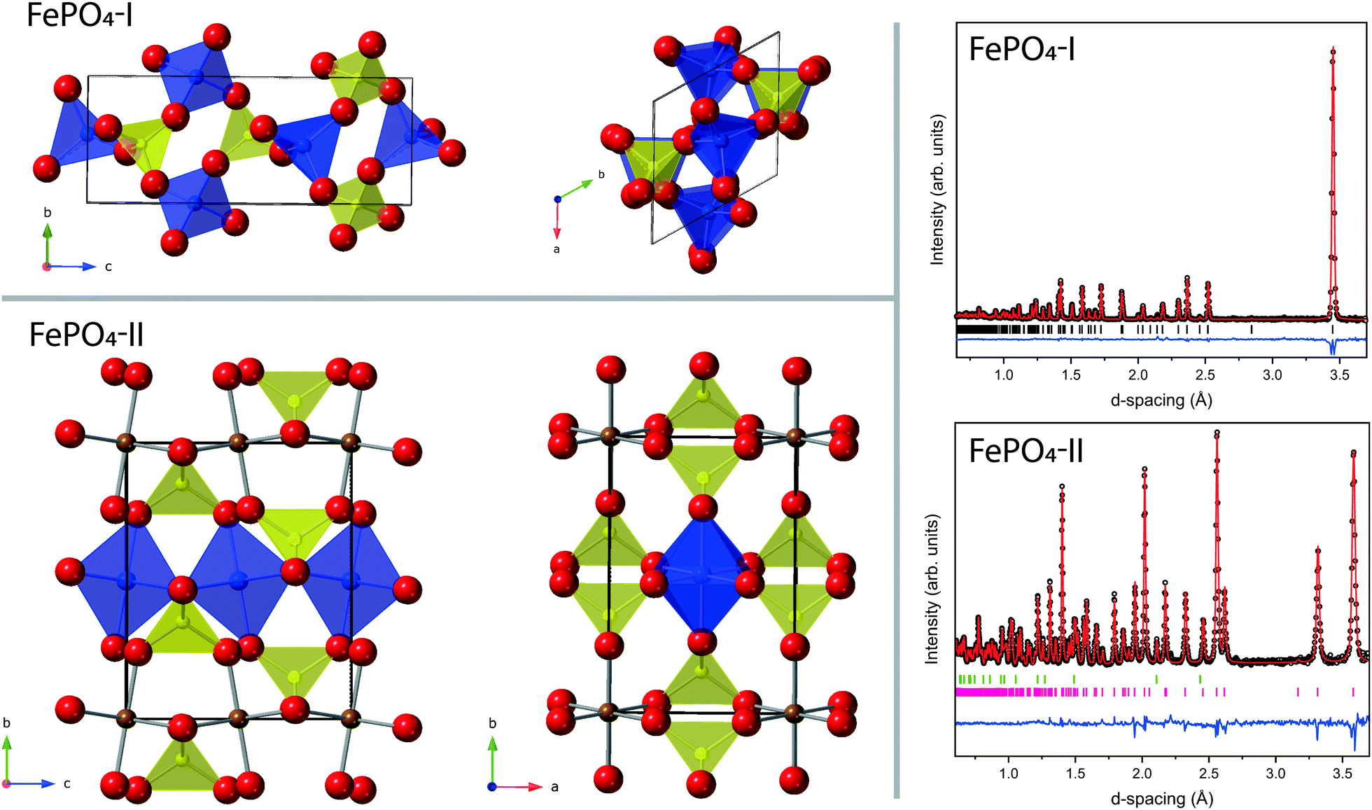 | ||
| Fig. 1 Top left: Ambient pressure structure of FePO4-I. Bottom left: Ambient pressure structure of FePO4-II. In both structures the yellow and purple polyhedra are the phosphorus and iron polyhedral units respectively and the red spheres the oxygen atoms. The FeO6 octahedra in FePO4-II are only shown in purple for one row along the c-axis, for clarity. The black outline indicates the unit cell. Top right: Ambient pressure neutron diffraction patterns and Rietveld fit for FePO4-I. Bottom right: Ambient pressure neutron diffraction patterns and Rietveld fit for FePO4-II. In both diffraction patterns the open black circles are the measured data, the solid red line is the Rietveld fit, the blue trace is the residual to the fit, the vertical tick marks index reflections to the P3121 for FePO4-I and Cmcm structure for FePO4-II respectively, also shown in the pattern of FePO4-II are the tick marks (in green) for the reflections of the contaminant phase MgO. | ||
Some applications of FePO4 include use as a catalyst in the manufacture of acrylic composites,3 oxidation prevention of metals,4 base coating for improved paint adhesion5 and as intercalated electrodes in lithium-ion batteries.6 It also finds an application as an approved pesticide in organic farming.7
Mössbauer studies show that phase-I is antiferromagnetic with a Néel temperature of 25 K.8 This is confirmed by susceptibility and neutron diffraction measurements which also suggested spin-reorientation transition at ∼17 K.9 In contrast, phase-II has a Néel temperature of ∼60 K with weak chain coupling leading to a relaxation phenomena between 43 K and TN. Phase-I has a resistivity greater than 4 × 10¹³ Ω cm and phase-II at room temperature is an insulator with a resistivity of 2 × 10⁷ Ω cm.10
The physical and structural properties of many ABO4-type oxides have been well studied,11 these include the orthophosphates, vanadates12 and quartz-like silicates13e.g. CrPO4,14 TiPO415 and InPO4.16 Some of these materials have been studied because they are homeotypes of α-quartz. Varying the cation size changes the level of distortion in the material through chemical means. The use of high-pressures on these homeotypes helps to understand silica polymorphism at less experimentally achievable pressures, to aid our understanding of processes which occur in the Earth's mantle.17,18 The orthophosphates are of interest, as the structures are intermediate between purely tetrahedral (quartz-like) and purely octahedral coordinated cations. Orthophosphates are predicted to undergo phase transitions to the latter under compression. An example where this has been observed is AlPO4 (pure tetrahedral), which transforms to a highly crystalline CrVO4 structure (mixed tetrahedral/octahedral) under compression and laser annealing. Further compression of this phase at ambient temperature shows a continuous transformation complete by ∼75 GPa to a monoclinic distorted CaCl2 structure (pure octahedral).17
The room temperature high-pressure behaviour of phase-I has been previously investigated by X-ray diffraction and Raman spectroscopy and found to transform to the orthorhombic phase (phase-II) at around 2.5 GPa. This is accompanied by a significant amount of amorphisation, and upon recovery does not convert back to phase-I but remains a mixture of poorly crystalline phase-II and amorphous FePO4.19 Such behaviour is similar to that observed in SiO2, which forms an ordered sixfold coordinated structure at 60 GPa.20 However, the presence of the amorphous material prevented a detailed structural study of phase-II at high pressure. There has also been. theoretical work published on the relative stability of phase I and II.21
For the present study, highly crystalline phase-II is instead synthesised and recovered to ambient conditions, as described by Kinomura et al.22 This allows the crystallographic changes in the structure of phase-II to be determined starting from ambient pressure up to a pressure of ∼8 GPa. In particular we have been able to determine the behaviour of the FeO6 and PO4 polyhedra. To complement this study, we have performed the equivalent diffraction study on phase-I. In addition, Raman scattering and magnetic measurements have been performed to support the work.
2 Experimental
2.1 Synthesis and characterisation
Trigonal phase-I was prepared by mixing stoichiometric amounts of dried Fe2O3 and (NH4)2HPO4. The ground powder was annealed at 1173 K for 24 hours in air.2 The resulting material is beige in colour and was confirmed to be pure phase-I by X-ray diffraction (details below). To synthesise phase-II, approximately 200 mg of phase-I was sealed within a platinum capsule and mounted inside a high temperature gasket assembly.23 The gasket assembly was compressed to ∼5 GPa within a V4 Paris-Edinburgh Press24 and annealed at ∼1200 K for 60 minutes. The temperature was decreased to ambient and the sample pressure slowly returned to ambient. The sample was removed from the platinum capsule, and the sample colour had changed to pale green. An X-ray diffraction pattern confirmed the transformation to the orthorhombic Cmcm phase, using a Bruker Phaser D2 with a 2θ range of 15–80° and a step size of 0.01°. The synthesis process was repeated to produce multiple batches, which were all confirmed individually to be single phase, and then combined. A neutron powder diffraction measurement was performed on both phases using the POLARIS instrument at the ISIS Neutron and Muon Source, UK.252.2 High-pressure neutron diffraction
High-pressure neutron-diffraction measurements were performed on the PEARL instrument at the ISIS Neutron and Muon Source, UK.26 The sample was loaded into a TiZr null-scattering encapsulated gasket.27 Phase-I was loaded within a standard single toroidal setup, and phase-II was loaded into a double toroidal setup, both using zirconia toughened alumina anvils.28 In both cases, a lead pellet was included with the sample to act as a pressure marker29 and perdeuterated methanol![[thin space (1/6-em)]](https://www.rsc.org/images/entities/char_2009.gif) :ethanol (4:1 by volume) was included as a pressure-transmitting medium.30 Load was applied to the assemblies using a V3 Paris-Edinburgh press.24 Time-of-flight (ToF) diffraction patterns were obtained in the transverse geometry and diffraction data were collected for ∼2 hours per pressure step for phase-I and ∼8 hours for phase-II. The data were reduced and corrected for anvil attenuation using Mantid.31 The resulting ToF diffraction patterns were analysed using the GSAS suite of programmes.32
:ethanol (4:1 by volume) was included as a pressure-transmitting medium.30 Load was applied to the assemblies using a V3 Paris-Edinburgh press.24 Time-of-flight (ToF) diffraction patterns were obtained in the transverse geometry and diffraction data were collected for ∼2 hours per pressure step for phase-I and ∼8 hours for phase-II. The data were reduced and corrected for anvil attenuation using Mantid.31 The resulting ToF diffraction patterns were analysed using the GSAS suite of programmes.32
2.3 Raman spectroscopy
Raman spectra were obtained in back scattering geometry using a Princeton Instruments SP2500i spectrometer fitted with a 1800 g mm−1 holographic blaze grating. A 532 nm diode laser was focused using a 20× Mitutoyo objective with a power of 5 mW at the sample position. All spectra were obtained at room temperature. The Raman measurements obtained at high-pressure were performed in a Almax Nitro membrane driven diamond anvil cell (DAC) equipped with 500 μm culet diamonds, a ruby sphere was included in the sample chamber to act as a pressure calibrant, using the fluorescence method.33 Methanol:ethanol (4:1) was also included as a pressure transmitting medium.
2.4 Magnetic characterisation
Magnetisation measurements were performed with a Quantum Design MPMS3 SQUID magnetometer in VSM (Vibrating Sample Magnetometry) mode. Finely ground samples (typically ∼20 mg) were loaded into gelatine capsules, and held in plastic straws within the SQUID at 300 K. Measurements of the DC magnetisation were made as a function of temperature on warming (M vs. T) over the range 4–370 K in an applied field of 100 Oe. Both field-cooled (FC) and zero-field-cooled (ZFC) data were collected.3 Results
3.1 Ambient pressure structure
The neutron diffraction patterns and associated Rietveld refined fits to the phase-I and phase-II structures are shown in Fig. 1. The results of the refinements of both phases are presented in Table 1. Phase-I is shown to be single phase, and the structure is comparable to that previously published.34 The sample of phase-II is contaminated with a small quantity of MgO from the gasket assembly and the results of the refinement are in reasonable agreement with previous published data collected by X-ray diffraction.35| Parameter | FePO4-I | FePO4-II |
|---|---|---|
| Space group | P3121 | Cmcm |
| a (Å) | 5.03783(7) | 5.23106(19) |
| b (Å) | 5.03783(7) | 7.7745(3) |
| c (Å) | 11.2498(3) | 6.3326(2) |
| Unit cell volume (Å3) | 247.265(6) | 257.540(18) |
| Fex | 0.4568(5) | 0 |
| Fey | 0 | 0 |
| Fez | 0.33333 | 0 |
| Px | 0.4570(9) | 0 |
| Py | 0 | 0.3504(2) |
| Pz | 0.83333 | 0.25 |
| O(1)x | 0.4153(7) | 0 |
| O(1)y | 0.3164(6) | 0.24185(13) |
| O(1)z | 0.39594(17) | 0.05057(16) |
| O(2)x | 0.4113(8) | 0.2437(2) |
| O(2)y | 0.2650(6) | 0.46706(13) |
| O(2)z | 0.8752(2) | 0.25 |
| wRp, Rp | 3.1,4.4 | 3.5,4.9 |
| χ 2 | 3.8 | 4.9 |
The work of Baur looked at the distortions of PO4 tetrahedra in many materials.36 It was shown that there was a range of P–O bond distances with an average value of 1.537 Å and the tetrahedral angles O–P–O ideally being ∼109.5°. However, the majority of PO4 tetrahedra are distorted through variations in P–O bond distances and O–P–O bond angles. Distortions in Fe and P polyhedra can be quantified using distortion indices (DI), defined as

 the mean bond distance within the polyhedron. A value of zero indicates an ideal undistorted polyhedron. The DI for the polyhedra of phases-I- and II at ambient pressure are given in Table 2, showing that the polyhedra in phase-II are more distorted than in phase-I.
| Parameter | FePO4-I | FePO4-II |
|---|---|---|
| P–O(1) (Å) | 1.534 | 1.519 |
| P–O(2) (Å) | 1.538 | 1.565 |
| 〈P–O〉 (Å) | 1.536 | 1.542 |
| DIPO | 0.0012 | 0.0148 |
| Fe–O(1) (Å) | 1.848 | 1.907 |
| Fe–O(2) (Å) | 1.857 | 2.090 |
| 〈Fe–O〉 (Å) | 1.852 | 2.029 |
| DIFeO | 0.0024 | 0.0401 |
3.2 Compressibility of phase-I and -II
Upon compression there are no unexpected changes in the diffraction patterns of phase-I up to ∼1.7 GPa. However, above this there is a decrease in the intensity of reflections, most apparent in the (102) reflection around 3.37 Å (Fig. 2), with the emergence of a new broad feature at ∼3.56 Å. This broad peak can be approximately indexed as the (111) reflection of the orthorhombic phase-II. The reflections of phase-I disappear completely upon further compression to ∼2.28 GPa, and the broad (111) reflection of phase-II increases in intensity but remains broad. The intensity and width remain unchanged between ∼2.28 GPa and 4.2 GPa. Upon recovery to ambient pressure the sample does not revert back to phase-I and the crystallinity does not return.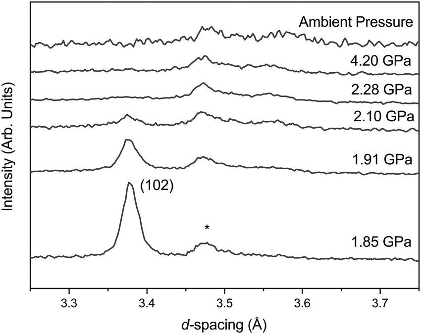 | ||
| Fig. 2 Neutron diffraction patterns of FePO4-I with increasing pressure. The reflection at ∼3.37 Å is the (102) reflection of FePO4-I, the reflection at ∼3.47 Å is the (asterisk) reflection of the Al2O3 from the anvil and the emerging but broad feature at ∼3.56 Å can be indexed as the (111) reflection of FePO4-II. | ||
Diffraction data collected in a vanadium holder on the POLARIS instrument of the recovered sample show broad reflections sitting on an amorphous-like background. The crystalline peaks can be indexed to that of phase-II but not fitted to any acceptable metric by Rietveld refinement techniques as a result of the strained and broad nature of the reflections (see ESI†) suggesting that only phase-II is present albeit strained and poorly crystalline form as indicated by the width of the (111) reflection. The recovered state of the sample is referred to here as phase-Ir.
Prior to the start of the transformation to the strained orthorhombic phase no discontinuous behaviour is observed and the compressibilities of the unit-cell axes are 14.0(4) TPa−1 for the a-axis and 6.8(2) TPa−1 for the c axis. The variation in unit-cell volume with pressure has been fitted with a 2nd and 3rd order Birch–Murnaghan equation of state (EoS); the fits are shown in the ESI,† and the results given in Table 3. A value of 24 GPa for B0 agrees with that previously reported by Pasternak et al.19
| Phase (BM order) | V 0 | B 0 | B′ |
|---|---|---|---|
| I (2nd) | 285.14(11) | 25.4(3) | — |
| I (3rd) | 285.28(19) | 24.2(12) | 5.5(16) |
| II (2nd) | 256.99(10) | 111(1) | — |
| II (3rd) | 257.19(14) | 104(4) | 5.7(10) |
| Phase | Median compressibility K (TPa−1) | ||
|---|---|---|---|
| a | b | c | |
| I | 14.01(39) | 14.01(39) | 6.75(19) |
| II | 0.97(14) | 2.50(17) | 3.37(15) |
In contrast phase-II remains crystalline up to ∼8 GPa (see Fig. 3) and no changes in crystal symmetry are observed. The determined unit-cell volumes have been fitted with a Birch–Murnaghan EoS and the values are given in Table 3, and no discontinuous behaviour in unit-cell volume is observed. The determined value of bulk modulus (B0) of 104(4) GPa is significantly higher than that determined for phase-I of 24 GPa. However, given that phase-II is 23% higher in density than phase-I this is not surprising.22 The value is similar to that reported previously by Pasternak et al. of 96 GPa which was determined from a sample formed by compression of phase-I and measured in the presence of the amorphous material and strained phase-II.19 Other iso-structural Cmcm materials show similar values of B0 for example, 97(6) GPa and 118(7) GPa for InPO4 and AlPO4 respectively.37,38 Similar increases in B0 are observed in SiO2 when transformed from the α-quartz form to coesite (∼38.5 GPa to 93 GPa).39
 | ||
| Fig. 3 Neutron diffraction patterns of FePO4-II with increasing pressure. | ||
Table 3 shows the behaviour of the individual unit-cell axes of phase-II; the c-axis is the least compressible and the a and b-axes are significantly more compressible, with the b-axis slightly stiffer than of the a-axis (see Table 3). The c-axis is the direction in which the chains of FeO6 octahedra are formed explaining the resistance in comparison to the other directions (Fig. 1). Upon compression to 8.4 GPa the angle between the octahedra (O(2)–O(2)′–O(2)′′) increases from 162.0(2)° to 175.7(9)°.
3.3 Polyhedral behaviour with pressure
Fig. 4 shows the variation in the FeO4 and PO4 tetrahedra of phase-I up to 1.7 GPa beyond which the phase transition described above occurs. All of the Fe–O bonds in the tetrahedra decrease in length with increasing pressure, resulting in a decrease in tetrahedral unit volume (see Fig. 4). The bond lengths decrease at a similar rate, so no measurable change in the distortion of the FeO4 tetrahedra are observed. The PO4 tetrahedra behave differently, with the longer P–O bonds of the tetrahedra contracting with pressure and the shorter bonds extending. Overall this results in an increase of the tetrahedral unit volume, though still without a measurable change in distortion. This is instead accommodated by a change in angle between the Fe- and P-tetrahedra, which decreases with applied pressure (see Fig. 4).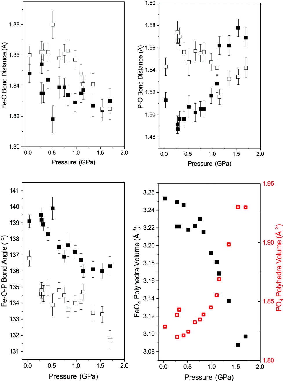 | ||
| Fig. 4 Polyhedra behaviour in FePO4-I with pressure. Top left: Variation in the distinct Fe–O bond lengths in the FeO4 tetrahedra (Fe–O(1) filled squares and Fe–O(2) open squares). Top right: Variation in the two distinct P–O bond lengths in the PO4 tetrahedra (P–O(1) filled squares and P–O(2) open squares). Bottom left: Variation in distinct Fe–O–P bond angles (filled squares – Fe–O(1)–P and open squares –Fe–O(2)–P) between the PO4 and FeO4 tetrahedra. Bottom right: Variation in volume of the PO4 (open red squares) and FeO4 tetrahedra (filled black squares). | ||
The behaviour of the octahedral Fe–O bonds in phase-II are shown in Fig. 5 with the longer of the Fe–O bonds decreasing in length whilst the shorter Fe–O bond show very little change with increasing pressure. The longer Fe–O bonds lie in the a–c plane and the shorter Fe–O bonds are tilted off axis along b. The combination of these two opposing bond length changes within the polyhedra result in a decrease in the distortion of the FeO6 polyhedra as shown by a decrease in the distortion index (DIFeO, Fig. 5).
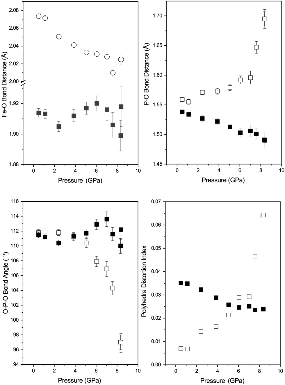 | ||
| Fig. 5 Polyhedra behaviour of FePO4-II with pressure. Top left: Variation in Fe–O bond lengths in the FeO6 octahedra (Filled squares – Fe–O(1) and open squares Fe–O(2)). Top right: Variation in P–O bond lengths in PO4 tetrahedra (Filled squares – P–O(1) and open squares P–O(2)). Bottom left: Variation in O–P–O bond angles (solid squares – O(1)–P–O(1) and the filled squares O(2)–P–O(2)) in the PO4 tetrahedra. Bottom right: Variation in the distortion indices (DIPO) for the PO4 tetrahedra (open squares) and FeO6 octahedra (DIFeO) shown by filled squares. | ||
The behaviour of the bond lengths in the PO4 tetrahedra of phase-II are shown in Fig. 5. At ambient pressure the two distinct P–O bond lengths are similar, however, with increasing pressure the P–O(1) bonds decrease in length and the longer P–O(2) bonds show a significant increase in length. Similarly, the O(1)–P–O(1) and O(1)–P–O(2) bond angles show very little variation within experimental error, however, the O(2)–P–O(2) bond angle shows a significant pressure dependence and a decrease away from the ideal tetrahedral value of 109.5°. The distortion indices (DIPO) for the PO4 tetrahedra show an increase with compression in contrast to that seen for the FeO6 octahedra. This is different to the behaviour of the isostructural CrVO4 structured InPO4 at high pressure.37 Upon compression of orthorhombic InPO4 both of the P–O bonds in the PO4 tetrahedra decrease in length at a similar rate to each other, and both of the O–P–O angles increase, resulting in no change in overall distortion of the tetrahedral unit with increasing pressure.
In the compression study of AlPO4 the transition from the orthorhombic phase to a monoclinic phase is observed in which both P and Al are octahedrally coordinated.17 In this phase, there is an elongation of the P–O distances, and a contraction of the Al–O distances with pressure. This transition is sluggish in nature occurring over the range 46–76 GPa (as is the case of the equivalent transition in SiO2). The transformation requires such high pressures as a result of the highly covalent nature of the P–O bonds.41 Whilst we do not see direct evidence of a transformation to a third phase of FePO4 we observe an increased distortion of the PO4 tetrahedra, which may well result in a phase transition at higher pressure, or there is a tendency for the co-ordination number of the phosphate polyhedra to be increasing beyond 4. In iso-structural materials (InPO4 and TiPO4) calculations suggest at high pressure a transformation to a wolframite structure occurs, in which the PO6 and In/TiO6 octahedra are irregular, albeit at a significantly higher pressure than the current study.12 Experimentally, symmetrisation of the TiO6 polyhedra was also observed in TiPO4 with pressure42 and an increase in co-ordination of the PO polyhedra from 4 to 5. The work of Errandonea and Manjón, based upon relative ionic radii suggest that with increasing pressure a structural transition from orthorhombic Cmcm to monoclinic C2/m or P2/c symmetry may occur in FePO4-II. However, no indication of the expected transition pressure is provided.43 It may be that in the current study any initial distortion upon going to lower crystallographic symmetry may be small and hence determination of its effect crystallographically may be beyond the resolution of the current experimental setup.
3.4 Raman measurements
Fig. 6 shows the Raman spectrum of phase-I as synthesised and is compared to that previously reported and shown to be in good agreement.44 The Raman spectrum is dramatically different to that of the orthorhombic phase-II (Fig. 6). Based upon theoretical work of Dwivedi et al. on the Raman spectrum of InPO4, we are able to tentatively assign the modes in the spectrum as shown in Fig. 6,37 the Raman modes are interpreted in terms of frequencies of PO4 tetrahedra as the covalent P–O bonds will result in higher intensity modes than the Fe–O bonds which are more ionic in character.45 The sample of phase-Ir from the neutron large-volume high-pressure compression experiment was recovered from the encapsulated gasket and the Raman spectra obtained and is shown in Fig. 6. This is clearly similar to that of phase-II, with some remnants of the signal from phase-I, a similar spectrum is seen from the sample compressed in the DAC and recovered back to ambient pressure (Fig. 6). Changes to the Raman spectrum of phase-I have also been followed upon compression to 5 GPa. The majority of vibrational modes harden or are invariant with increasing pressure and just below 2 GPa there is an abrupt change in the Raman signal to that of orthorhombic phase-II similar to that observed in the neutron diffraction experiment upon compression of phase-I (see ESI†). In phase II the vibrational modes observed in the Raman spectrum harden or are invariant with increasing pressure up to the maximum pressure of ∼5 GPa.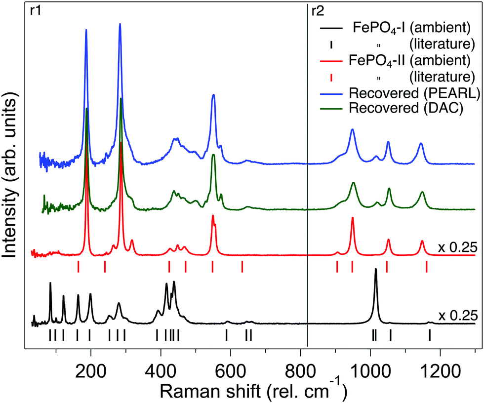 | ||
| Fig. 6 Raman spectra of FePO4. From bottom to top: Raman spectrum of FePO4-I as synthesised (black trace), the vertical tick marks below indicate the previously reported assigned peak positions of the Raman spectra.44 Raman spectrum of bulk synthesised FePO4-II (red trace), the vertical tick marks below indicate the assigned Raman peaks from the iso-structural InPO4.37 Green trace: Raman spectrum of FePO4 at ambient pressure recovered from a sample of FePO4-I compressed to 5 GPa in the DAC. Blue top trace: Raman spectrum of FePO4-Ir at ambient pressure recovered from sample of FePO4-I compressed to 4.2 GPa in the Paris-Edinburgh press. The spectra shown are combination of two separate spectral regions (r1 and r2) where the 1800 g mm−1 grating was centred on 460 and 940 rel cm−1, respectively. | ||
3.5 SQUID magnetometry
Plots of the inverse susceptibility (χ−1) behaviour with temperature of both phases of FePO4 are shown in Fig. 7. The Néel temperature of phase-I was found to be 28.0(5) K, which increases to 56.5(5) K for phase-II. In the paramagnetic regime, the data are fitted to the Curie–Weiss relation, where θ, is the Curie temperature, and C, the Curie constant. The final determined values to the ZFC data are shown in Fig. 7(a). The calculated effective moments of the Fe cations are 5.45μb and 6.45μb for phase-I and -II respectively. The value for phase-II is slightly different to the reported value 6.06μb,10 which may be due to the presence of the MgO impurity providing additional paramagnetic background to the present study. This is supported by the otherwise close agreement in fitted Curie temperature from the same study, 110(1) K. Aside from this, the value of the effective moment is close to ∼5.9μb, as expected from spin-only contributions from octahedrally coordinated Fe3+.46 Phase-I, which had no measurable crystalline impurity phases in the neutron data, has a lower effective moment than expected, but instead lies in closer agreement with previous literature values for octahedrally coordinated LiFe2+ PO4 (μeff = 5.45μb, θ = −88 K, TN = 50 K),47 and NaFe2+ PO4 (μeff = 5.48μb, θ = −147 K, TN = 61 K).48 The tetrahedral coordination in phase-I results in lower orbital splitting energies, which increases electron–electron repulsion between them, and causes the vast majority of simple tetrahedral complexes to be high-spin. For d5-complexes this means that the theoretical spin-only effective moment is identical as that for octahedral coordination. An alternative cause for a lower effective moment, may be an oxygen deficiency, resulting in a proportion of Fe2+ in the sample. Refining the two site occupancies against the ambient neutron-diffraction data gives values of 0.97(1) and 0.96(1). This would average to give Fe2.7+, still not completely accounting for the measured value being lower than expected. Alternatively, there could be a mixture of high- and low-spin Fe3+, though this would have been evident in the isomer shift in previous Mössbauer studies, which appear consistent with a high-spin arrangement. It is therefore likely that some undetectable (via neutron diffraction) level of impurity in the precursor material exists.
 | ||
| Fig. 7 Temperature dependence of magnetic susceptibility of FePO4. (a) ZFC inverse susceptibility of the two phases of FePO4 at ambient pressure, fitted to Curie–Weiss law (red dashed line, see text). (b) ZFC (solid/squares) and FC (dashed/circles) inverse susceptibilities of both phases at ambient pressure, compared with that of the recovered sample (FePO4-Ir) from 4.2 GPa (red squares and circles) below TN. | ||
No anomalies are observed in the susceptibility of phase-I at ∼17 K as initially reported by Battle et al.,9 and confirmed more recently by Grandjean et al. with Mössbauer, attributed to an antiferromagnetic spin reorientation, which may be due to differences in measuring field (see ESI†).49
Phase-Ir, shows very different magnetisation behaviour from both phase-I and phase-II. While the Néel temperature for phase-II is greater than phase-I, it is greater still for phase-Ir, 66(2) K. Additionally there is a clear split in the FC and ZFC datasets, which is not observed to the same level in either phase-I or phase-II. This suggests that there is a significant degree of uncompensated moment in the antiferromagnetic state. This type of behaviour may be attributed to a number of phenomena, such as super-paramagnetism (as is observed with DyPO450), domain wall pinning, clustering, or spin-glass behaviour. Literature measurements on amorphous MnPO4, obtained by delithiation of LiMnPO4, and annealing at 970 K in O2 atmosphere, showed a similar large discrepancy in FC/ZFC curves, though the authors suggest that an impurity phase may be the cause of this.51 In the present study, this spin canting may be due to a highly strained frustrated intermediate state between phase-I and -II, which is supported by the evidence for reduced crystallinity in the diffraction data. Similar effects are seen in CoPO4 units when frustrated through layering in the compound Ba(CoPO4)2.52 Further time dependent, and AC measurements would be required to aid differentiating between these possibilities, which are beyond the scope of the present study.
4 Conclusions
We have for the first time followed the structural behaviour of both the trigonal and orthorhombic phases of FePO4 as a function of pressure at room temperature using neutron diffraction. With increasing pressure the FeO4 and PO4 tetrahedra of phase-I show no significant change in distortion however, the FeO4 units decrease in volume and the PO4 tetrahedra increase in volume. At ∼1.8 GPa phase-I appears to partially amorphise, concurrent with the appearance of the orthorhombic phase-II with broad reflections indicating a highly strained state. This state is recoverable when the pressure is reduced back to ambient conditions. Raman measurements on the recovered sample show properties similar to that of pure phase-II, while SQUID data shows a large increase in TN, and large uncompensated moment in the antiferromagnetic state. In contrast to the behaviour of phase-I, the PO4 tetrahedra in phase-II increase in volume and increase in distortion with pressure, and the FeO6 octahedra show an decrease in volume and a small decrease in distortion from regular octahedra. The behaviour described of both the trigonal and orthorhombic phases of FePO4 could have implications for geological iso-structural materials. Structural studies of many geologically relevant materials may not be achievable using neutron diffraction techniques as a result of the higher pressures required to induce such structural transformations, and the behaviour observed in FePO4 can be used to extrapolate behaviour in minerals. Studies at higher pressures may also be limited by the degree of resolution required to determine accurate crystallographic information at these extremes.Conflicts of interest
There are no conflicts to declare.Acknowledgements
We acknowledge the support of ISIS, STFC for providing access to the PEARL instrument53 and Express access to the POLARIS instrument54–56 and the help of Ron Smith (ISIS) for providing diffraction data and support on the POLARIS instrument. We also thank ISIS, STFC for access to the Materials Characterisation Laboratory and facilities therein. Finally, we acknowledge Professor Kevin Knight for his helpful discussions related to this work. British Crown Owned Copyright 2021/AWE. Published with permission of the Controller of Her Britannic Majesty's Stationery Office.References
- H. N. Ng and C. Calvo, Can. J. Chem., 1975, 53, 2064–2067 CrossRef CAS.
- P. Battle, C. Gibb, G. Hu, D. Munro and J. Attfield, J. Solid State Chem., 1986, 65, 343–350 CrossRef CAS.
- M. Gadgil and S. Kulshreshtha, J. Solid State Chem., 1994, 111, 357–364 CrossRef CAS.
- B. Ptacek, F. Dalard and J. Rameau, Surf. Coat. Technol., 1996, 82, 277–283 CrossRef CAS.
- S.-J. Lee, D. Hung-Toan, Y.-H. Chena and H.-C. Peng, Int. J. Electrochem. Soc., 2016, 11, 2306–2316 Search PubMed.
- A. K. Padhi, J. Electrochem. Soc., 1997, 144, 1188 CrossRef CAS.
- S. Freitag, E. M. Krupp, A. Raab and J. Feldmann, Environ. Sci.: Processes Impacts, 2013, 15, 463–469 RSC.
- W. Bruckner, W. Fuchs and G. Ritter, Phys. Lett. A, 1967, 26, 32–33 CrossRef.
- P. D. Battle, A. K. Cheetham, C. Gleitzer, W. T. A. Harrison, G. J. Long and G. Longworth, J. Phys. C: Solid State Phys., 1982, 15, L919–L924 CrossRef CAS.
- M. E. Arroyo y de Dompablo, N. Biskup, J. M. Gallardo-Amores, E. Moran, H. Ehrenberg and U. Amador, Chem. Mater., 2010, 22, 994–1001 CrossRef CAS.
- E. J. Baran, J. Mater. Sci., 1998, 33, 2479–2497 CrossRef CAS.
- S. López-Moreno and D. Errandonea, Phys. Rev. B: Condens. Matter Mater. Phys., 2012, 86, 104112 CrossRef.
- L. Gracia, A. Beltrán and D. Errandonea, Phys. Rev. B: Condens. Matter Mater. Phys., 2009, 80, 094105 CrossRef.
- M. Touboul and K. Melghit, J. Mater. Chem., 1995, 5, 147–150 RSC.
- N. Kinomura, F. Muto and M. Koizumi, J. Solid State Chem., 1982, 45, 252–258 CrossRef CAS.
- R. C. L. Mooney, Acta Crystallogr., 1956, 9, 113–117 CrossRef CAS.
- J. Pellicer-Porres, A. M. Saitta, A. Polian, J. P. Itié and M. Hanfland, Nat. Mater., 2007, 6, 698–702 CrossRef CAS PubMed.
- J. Haines and O. Cambon, Z. Kristallogr. – Cryst. Mater., 2004, 219, 314–323 CrossRef CAS.
- M. P. Pasternak, G. K. Rozenberg, A. P. Milner, M. Amanowicz, T. Zhou, U. Schwarz, K. Syassen, R. Dean Taylor, M. Hanfland and K. Brister, Phys. Rev. Lett., 1997, 79, 4409–4412 CrossRef CAS.
- S. M. Sharma and S. Sikka, Prog. Mater. Sci., 1996, 40, 1–77 CrossRef CAS.
- N. Lethole, H. Chauke and P. Ngoepe, Comput. Theor. Chem., 2019, 1155, 67–74 CrossRef CAS.
- N. Kinomura, M. Shimada, M. Koizumi and S. Kume, Mater. Res. Bull., 1976, 11, 457–460 CrossRef CAS.
- Y. Le Godec, M. T. Dove, D. J. Francis, S. C. Kohn, W. G. Marshall, A. R. Pawley, G. D. Price, S. A. T. Redfern, N. Rhodes, N. L. Ross, P. F. Schofield, E. Schooneveld, G. Syfosse, M. G. Tucker and M. D. Welch, Mineral. Mag., 2001, 65, 737–748 CrossRef CAS.
- J. M. Besson, R. J. Nelmes, G. Hamel, J. S. Loveday, G. Weill and S. Hull, Phys. B, 1992, 180, 907–910 CrossRef.
- R. I. Smith, S. Hull, M. G. Tucker, H. Y. Playford, D. J. McPhail, S. P. Waller and S. T. Norberg, Rev. Sci. Instrum., 2019, 90, 115101 CrossRef CAS PubMed.
- C. L. Bull, N. P. Funnell, M. G. Tucker, S. Hull, D. J. Francis and W. G. Marshall, High Press. Res., 2016, 36, 493–511 CrossRef.
- W. G. Marshall and D. J. Francis, J. Appl. Crystallogr., 2002, 35, 122–125 CrossRef CAS.
- P. F. Funnell, C. J. Ridley and C. L. Bull, In preparation.
- A. D. Fortes, RAL Technical Reports, 2019, RAL-TR-2019-002.
- S. Klotz, J. C. Chervin, P. Munsch and G. L. Marchand, J. Phys. D: Appl. Phys., 2009, 42, 075413 CrossRef.
- O. Arnold, J. C. Bilheux, J. M. Borreguero, A. Buts, S. I. Campbell, L. Chapon, M. Doucet, N. Draper, R. Ferraz Leal, M. A. Gigg, V. E. Lynch, A. Markvardsen, D. J. Mikkelson, R. L. Mikkelson, R. Miller, K. Palmen, P. Parker, G. Passos, T. G. Perring, P. F. Peterson, S. Ren, M. A. Reuter, A. T. Savici, J. W. Taylor, R. J. Taylor, R. Tolchenov, W. Zhou and J. Zikovsky, Nucl. Instrum. Methods Phys. Res., Sect. A, 2014, 764, 156–166 CrossRef CAS.
- B. H. Toby, J. Appl. Crystallogr., 2001, 34, 210–213 CrossRef CAS.
- K. Syassen, High Press. Res., 2008, 28, 75 CrossRef CAS.
- J. Haines, O. Cambon and S. Hull, Z. Kristallogr., 2003, 218, 193 CAS.
- M. E. Arroyo-de Dompablo, J. M. Gallardo-Amores and U. Amador, Electrochem. Solid-State Lett., 2005, 8, A564 CrossRef CAS.
- W. H. Baur, Acta Crystallogr., Sect. B: Struct. Sci., 1974, 30, 1195–1215 CrossRef CAS.
- A. Dwivedi, R. Kaiwart, M. Varma, S. Velaga and H. Poswal, J. Solid State Chem., 2020, 282, 121065 CrossRef CAS.
- H. K. Poswal, N. Garg, M. Somayazulu and S. M. Sharma, Am. Mineral., 2013, 98, 285–291 CrossRef CAS.
- H. Mao, B. Sundman, Z. Wang and S. Saxena, J. Alloys Compd., 2001, 327, 253–262 CrossRef CAS.
- M. J. Cliffe and A. L. Goodwin, J. Appl. Crystallogr., 2012, 45, 1321–1329 CrossRef CAS.
- J. S. Tse and D. D. Klug, Science, 1992, 255, 1559–1561 CrossRef CAS PubMed.
- M. Bykov, E. Bykova, M. Hanfland, H.-P. Liermann, R. K. Kremer, R. Glaum, L. Dubrovinsky and S. van Smaalen, Angew. Chem., Int. Ed., 2016, 55, 15053–15057 CrossRef CAS PubMed.
- D. Errandonea and F. J. Manjón, Prog. Mater. Sci., 2008, 53, 711–773 CrossRef CAS.
- M. Souleiman, P. Hermet, A. Haidoux, C. Levelut, J. Haines and O. Cambon, RSC Adv., 2013, 3, 22078–22086 RSC.
- M. Rokita, M. Handke and W. Mozgawa, J. Mol. Struct., 2000, 555, 351–356 CrossRef CAS.
- C. M. Julien, A. Ait-Salah, A. Mauger and F. Gendron, Ionics, 2006, 12, 21–32 CrossRef CAS.
- R. P. Santoro and R. E. Newnham, Acta Crystallogr., 1967, 22, 344–347 CrossRef CAS.
- I. Bobrikov, A. Balagurov, C.-W. Hu, C.-H. Lee, T.-Y. Chen, S. Deleg and D. Balagurov, J. Power Sources, 2014, 258, 356–364 CrossRef CAS.
- F. Grandjean and G. J. Long, Inorg. Chem., 2019, 58, 13314–13322 CrossRef CAS PubMed.
- T. Sorop, M. Evangelisti, M. Haase and L. de Jongh, J. Magn. Magn. Mater., 2004, 272-276, 1573–1574 CrossRef CAS.
- Y. Huang, J. Fang, F. Omenya, M. O'Shea, N. A. Chernova, R. Zhang, Q. Wang, N. F. Quackenbush, L. F. J. Piper, D. O. Scanlon and M. S. Whittingham, J. Mater. Chem. A, 2014, 2, 12827–12834 RSC.
- R. David, H. Kabbour, A. Pautrat and O. Mentré, Inorg. Chem., 2013, 52, 8732–8737 CrossRef CAS PubMed.
- C. L. Bull, C. J. Ridley, N. P. Funnell, C. Wilson and S. MacCleod, STFC ISIS Neutron and Muon Source, 2019 DOI:10.5286/ISIS.E.RB2000049-1.
- C. L. Bull, C. J. Ridley and N. P. Funnell, STFC ISIS Neutron and Muon Source, 2020 DOI:10.5286/ISIS.E.RB2090075-1.
- C. L. Bull, C. J. Ridley and N. P. Funnell, STFC ISIS Neutron and Muon Source, 2019 DOI:10.5286/ISIS.E.RB1990184-1.
- C. L. Bull, C. J. Ridley and N. P. Funnell, STFC ISIS Neutron and Muon Source, 2019 DOI:10.5286/ISIS.E.RB1990183-1.
Footnote |
| † Electronic supplementary information (ESI) available. See DOI: 10.1039/d1ma00227a |
| This journal is © The Royal Society of Chemistry 2021 |