
 Open Access Article
 This Open Access Article is licensed under a Creative Commons Attribution-Non Commercial 3.0 Unported Licence
Photoluminescence and electroluminescence characterization of high-performance near-infrared emitters based on 1,5-naphthyridin-4-ol-containing heteroleptic platinum(II) complexes†
Hagos Tesfay
Kidanu
 abc,
Jian Haur
Lee
abc and
Chin-Ti
Chen
*a
abc,
Jian Haur
Lee
abc and
Chin-Ti
Chen
*a
aInstitute of Chemistry, Academia Sinica, Taipei 11529, Taiwan, Republic of China. E-mail: chintchen@gate.sinica.edu.tw; Fax: +886 2 27831237; Tel: +886 2 55728542
bSustainable Chemical Science and Technology (SCST), Taiwan International Graduate Program (TIGP), Academia Sinica, Taipei 11529, Taiwan, Republic of China
cDepartment of Applied Chemistry, National Yang Ming Chiao Tung University, Hsinchu 30050, Taiwan, Republic of China
First published on 8th April 2021
Abstract
Four 1,5-naphthyridin-4-ol-containing platinum complexes, AtFOND, AtFNND, PBSOND, and PBSNND, have been synthesized and characterized for their photoluminescence (PL) and electroluminescence (EL) properties. In addition to supporting the aggregate/excimer formation of the four platinum complexes in the solid state, the absorption and emission spectra of the solution, dopant thin film, and solid state suggest that the metal–metal-to-ligand charge transfer (MMLCT) is the main reason for the very long emission wavelengths of λmax 770 and 774 nm for PL and EL of AtFOND, respectively. The MMLCT is inferable from the single-crystal X-ray structure, namely, the Pt–Pt contacts which are short (3.39 and 3.88 Å) and almost normal to the molecular planes of AtFOND. The solid-state PL quantum yield (PLQY) has been determined to be 9%, 58%, 53%, and 33% for AtFOND, AtFNND, PBSOND, and PBSNND, respectively. Although the four platinum complexes show green to yellow (λPLmax 523–546 nm) PL in diluted solution, all non-dopant OLEDs with a thin emissive layer (2 nm) based on AtFOND, AtFNND, PBSOND, and PBSNND display NIR (λELmax 704–774 nm) EL with EQE values of 1.8%, 6.5%, 4.0%, and 10.1%, respectively. The relatively high EQE (10.1%) of the PBSNND NIR OLED can be ascribed to the molecular alignment in the thin film that enhances the light outcoupling of the devices. Together with the single-crystal X-ray structure, the 2D-GIWAXS study provides convincing evidence for the advantageous molecular alignment of PBSNND.
Introduction
Different from displays and lighting, essentially invisible near-infrared (NIR) emitters find their niche applications in fibre optic telecommunication, night vision technologies, wound healing, and bioimaging and as chemosensing materials.1–5 For practical reasons, NIR organic light-emitting diodes (OLEDs) attract increasing research efforts due to their high electroluminescence (EL) efficiency.6–8 Most NIR emitters exhibit low EL efficiency, except for Pt complexes.9–11 Complexes, having a square planar molecular structure, are known to form excimers emitting long wavelengths in the deep red or NIR region (λmax > 700 nm).12–14 Due to the exciton self-trapping of excimers,15 the detrimental triplet–triplet annihilation, which is usually prevalent for a heavy metal-based phosphorescence emitter in a non-dopant thin film, is alleviated.16,17 NIR emissions from the excimer of Pt complexes have the advantage of high EL efficiency over other NIR emitters. A high external quantum efficiency (EQE) of >10%, even as high as >20%, has been reported in recent years.13,18Herein, we report four NIR emitting heteroleptic Pt complexes based on two 1,5-naphthyridin-4-ol (ND) derivatives, 4-hydroxy-8-phenoxy-1,5-naphthyridine (OPhNDH) and 4-hydroxy-8-dimethylamino-1,5-naphthyridine (dmaNDH) (Scheme 1), the Pt complexes of which have been demonstrated by us for high-performance hybrid white OLEDs before.19–21 By incorporating the second ligand, either 2-(4-methoxyphenyl)-5-(trifluoromethyl)pyridine (AtF) or 2-phenylbenzo[d]thiazole (PBS), the Pt complexes of AtFOND, AtFNND, PBSOND, and PBSNND (Scheme 1) have been synthesized and characterized. We have studied their photoluminescence (PL) and EL in detail. The voltage-independent NIR with λELmax of 774, 744, 726, and 702 nm has been observed for AtFOND, AtFNND, PBSOND, and PBSNND, respectively, among which an EQE as high as 10.1% has been achieved for PBSNND NIR OLEDs. Considering its moderate solid-state photoluminescence quantum yield (PLQY) of ∼32%, such an EQE is quite unusual. Through the study reported here, we have found that the unusual EQE is due to the enhanced light outcoupling of OLEDs, which was verified by 2D-GIWAXS and single-crystal X-ray crystallography.
 | ||
| Scheme 1 Synthetic route for AtFOND, AtFNND, PBSOND, and PBSNND. The chemical structures of OPhNDH and dmaNDH are depicted. | ||
Results and discussion
Molecular design and synthesis
The synthesis of the new platinum complexes follows the previous protocol (Scheme 1).19–21 However, instead of the common method via the Pt μ-dichloro-bridged dimer, the four heteroleptic Pt-complexes reported here were prepared through the corresponding monometallic Pt-complex, (AtF)2PtCl or (PBS)2PtCl. Compared with Pt μ-dichloro-bridged dimer counterparts, monometallic Pt-complexes have a more reasonable solubility, enabling the purification by column chromatography. Purer intermediate monometallic complexes facilitate the final synthesis of the four platinum complexes with much higher yields, although the purity of the two intermediate monometallic complexes isolated from the reaction is already good enough and we just used them directly without further purification. While the synthesis and preparation of ligands, AtF, PBS, and dmaNDH, readily followed a literature procedure,22,23OPhONDH was synthesized and prepared by a modified procedure23 with much improved yields (see the Synthesis and materials section for details). The formulation of these complexes was confirmed by NMR spectroscopy, mass spectrometry (see Fig. S1–S14, ESI†), and elemental analyses. Moreover, AtFOND, AtFNND and PBSNND complexes were structurally characterized by single-crystal X-ray crystallography.X-Ray crystallography
Single crystals of AtFOND, AtFNND, and PBSNND were grown from a dichloromethane/methanol solution. The ORTEP diagrams and some crystal data are shown in Fig. 1 and ref. 24, respectively. All three platinum complexes adopt a distorted square planar geometry and a trans conformation between two coordinating nitrogen atoms of AtF/PBS and OND/NND ligands. See Table S1 (ESI†) for selected bond distances and bond angles, including those from the DFT calculation and single-crystal X-ray structure. Although sharing a common ligand of AtF, the crystal of AtFOND and AtFNND grows in two different space groups, i.e., Pbcn for AtFOND and P![[1 with combining macron]](https://www.rsc.org/images/entities/char_0031_0304.gif) for AtFNND. More importantly, the molecular contact in the crystal of AtFOND and AtFNND is very different, although both AtFOND and AtFNND take a pair-wise stacking structure.
for AtFNND. More importantly, the molecular contact in the crystal of AtFOND and AtFNND is very different, although both AtFOND and AtFNND take a pair-wise stacking structure.
 | ||
| Fig. 1 Top three figures: ORTEP diagram of AtFOND, AtFNND, and PBSNND with thermal ellipsoids shown at about 50% probability level (Pt atoms in the bottom three figures are shown in higher level for clarity). Bottom three figures: molecular stacking diagram (from two viewing angles ∼90° difference) with an emphasis on the near-vertical (to the molecular plane) and short contacts (3.39 and 3.88 Å) among Pt atoms of AtFOND, but the side-ways sliding and long contacts among Pt atoms of AtFNND (6.24, and 6.52 Å) or PBSNND (5.62 Å). In the bottom three figures, all hydrogen atoms are removed for clarity. | ||
The crystal of AtFOND has short Pt–Pt contacts (3.39 and 3.88 Å), and the Pt–Pt contacts just slightly deviate from the normal direction of the molecular planes. Differently, the crystal of AtFNND has long Pt–Pt contacts (5.62 and 6.24 Å), and the Pt–Pt contacts much more deviate from the normal direction of the molecular planes. Essentially, such molecular stacking of AtFNND excludes the possible long wavelength absorption from the MMLCT excited state, of which short and near-vertical Pt–Pt contacts are prerequisites. We suggest that this is the reason for the bright yellow colour for the crystal of AtFNND but dark brownish red for AtFOND (Fig. 2). On the other hand, molecular packing is much tighter for AtFOND than AtFNND (Fig. 1), which is not favourable for a strong emission in the solid state and consistent with the photoluminescence images of both AtFOND and AtFNND as crystalline solids (Fig. 2).
 | ||
| Fig. 2 Solution and solid images of AtFOND, AtFNND, PBSOND, and PBSNND (from the left to right). Top row: in a degassed dilute dichloromethane solution of 1 × 10⁻⁵ M. Crystals or non-crystalline powders obtained from a solution process of a single crystal grown under 365 nm UV (centre row) and under ambient conditions (bottom row). | ||
Regarding PBSNND crystals, long (5.62 Å) and off-vertical Pt–Pt contacts between the molecular planes (Fig. 1) have been observed. Unfortunately, the solid of PBSOND obtained from the same single crystal growing process is not suitable for X-ray diffraction. Based on a similar yellowish orange colour for both solids of PBSOND and PBSNND (Fig. 2), we surmise that the molecular stacking of PBSOND has long and off-vertical Pt–Pt contacts, more similar to those of PBSNND or AtFNND rather than those of AtFOND. Based on the dark brownish red colour of AtFOND and its longest PL wavelength of 750 nm among the four platinum complexes, we can reasonably infer that AtFOND has a MMLCT excited state.
Among the four platinum complexes studied here, AtFOND is the only one showing MMLCT-origin absorption and emission in the solid state. By observing the molecular contacts in the single crystal of AtFOND, AtFNND, and PBSNND (Fig. S16, ESI†), no particular short π–π or other contacts but the near-vertical (along the normal direction) and short Pt–Pt contacts (3.39 and 3.88 Å) can be found for AtFOND only.
In summary, all four platinum complexes show deep red or NIR PL (Fig. 2 centre row) and EL (see the Electroluminescence properties section) in the solid state, which is very different from the green to yellow emission in solution (Fig. 2 top row). Accordingly, all four platinum complexes form aggregates/excimers in the solid state. From the X-ray crystallography data, only AtFOND is possible to have MMLCT in the aggregates/excimers. The solid state (powder and/or crystal) absorption spectra (see Fig. 3 right) of the four platinum complexes show an absorption onset around 650–700 nm for AtFOND, which is far longer than ∼570 nm of PBSOND and PBSNND, and ∼530 nm of AtfNND. Therefore, the solid state absorption spectra further support the existence of the MMLCT excited state of AtFOND, which is inferred from the single-crystal X-ray structure.
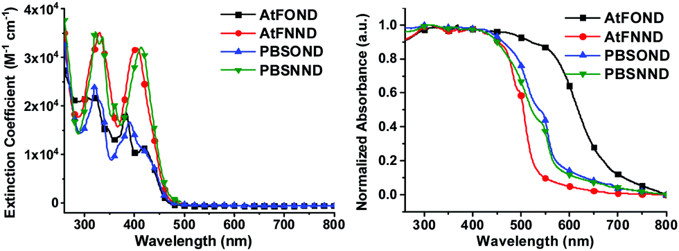 | ||
| Fig. 3 UV-vis absorption spectra of the studied platinum complexes in CH2Cl2 at a concentration of 1 × 10⁻⁵ M (left) and as a crystal/powder (right). | ||
UV-vis absorption spectroscopic analysis
The solution and solid-state UV-vis absorption spectra of the four platinum complexes are shown in Fig. 3, and the corresponding data are summarized in Table 1.| Pt complexes | λ max (ε) [nm] in CH2Cl2 (103 M−1 cm−1) | λ PLmax (nm) in CH2Cl2 | λ PLmax (nm) neat film | ϕ PL | τ p (μs) | ||
|---|---|---|---|---|---|---|---|
| 2 × 10⁻⁵ M | 2 × 10⁻⁴ M | 2 × 10⁻³ M | |||||
| a PLQY determined in degassed CH2Cl2 at 2 × 10⁻⁵ M using [Ru(bpy)3](PF6)2 (bpy = 2,2′-bipyridine) in acetonitrile as a reference (ϕPL = 0.062).25 The second number is the solid state (15 wt% dopants in the 4P-NPD thin film) PLQY determined by the integrating sphere method with monochromated incident light at a wavelength of 442 nm. b Room temperature PL lifetime determined in degassed CH2Cl2. | |||||||
| AtFOND | 419(11) | 532 | 548 | 690 | 770 | 0.09, 0.09 | 1.99 |
| AtFNND | 406(32) | 523 | 528 | 715 | 750 | 0.18, 0.58 | 1.17 |
| PBSOND | 414–416(11) | 543 | 587 | 711 | 740 | 0.24, 0.53 | 1.52 |
| PBSNND | 413(32) | 546 | 592 | 715 | 732 | 0.36, 0.32 | 0.71 |
These platinum complexes display two regions of absorbance, approximately 280–375 nm and 375–475 nm. The more intense short wavelength absorption in the near-UV region (< 375 nm) is mainly due to the ligand-based π–π* transitions that are associated with either (C^N) or (N^O) ligands. The less intense absorption bands at a longer wavelength (375–475 nm) could be assigned to some admixture of ligand-to-ligand charge transfer (LLCT) and singlet metal-to-ligand charge transfer (1MLCT) and/or triplet metal-to-ligand charge transfer (3MLCT) (5d → π*) electronic transitions.
Compared with those of AtFOND and PBSOND, the spectra of AtFNND and PBSNND show a very similar spectral feature, i.e., relatively featureless and much intense absorption bands. The featureless absorption bands can be attributed to a more charge transfer (CT) characteristic. Similar and more intense absorption bands have been observed for other ND-based heteroleptic platinum complexes, having morpholine- or piperidine-substituted ND.19,20 These have been attributed to the strong donating power of dialkylamino substituents, such as morpholinyl, piperidinyl, and dimethylamino groups. Our spectroscopic analysis is basically consistent with the calculated electron density of the HOMO (highest occupied molecular orbital) of the four platinum complexes, of which the electron density resides primarily on the OND or NND ligand, and secondarily on the Pt atom and the anisole group and phenyl group of AtF and PBS, respectively (Fig. 4). Accordingly, the stronger donor-containing ND ligand, i.e., NND, causes more featureless and more intense absorption bands.
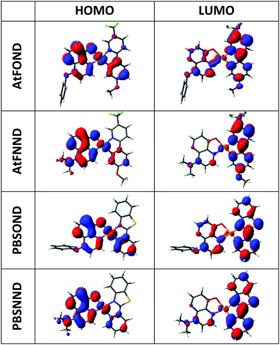 | ||
| Fig. 4 Calculated electron density contour plots of the frontier molecular orbitals of the studied complexes (isovalue = 0.0250). | ||
On the other hand, regardless of AtF or PBS, whenever OND is included as one of the coordination ligands, there are multiple absorption bands and their intensity is significantly reduced (Fig. 3). Moreover, the absorption energy gap of the four platinum complexes is determined by the OND or NND ligand, not by the AtF or PBS ligand. This is because the NND-containing platinum complexes always exhibit a shorter wavelength of λabmax (Table 1 and Fig. 3) than that of the OND-containing platinum complexes, regardless of the AtF or PBS ligand. Such spectroscopic results are very much consistent with that of the HOMO electrons that reside mostly on the OND or NND ligand, which dictate the absorption spectra of the four platinum complexes.
Photoluminescence spectroscopic analysis
The PL spectra of the studied platinum complexes in both solutions with varied concentrations and drop-cast thin films with varied host materials are shown in Fig. 5. Different from the absorption spectra, AtF or PBS (not OND or NND) is the decisive ligand for the PL spectra of the four platinum complexes. This is consistent with our DFT/TD-DFT calculations, revealing that the electron density of the LUMO (lowest unoccupied molecular orbital) primarily distributes on the AtF or PBS ligand, and sporadically on the Pt atom and the phenoxypyridine and dimethylaminopyridine of the OND and NND, respectively (Fig. 4).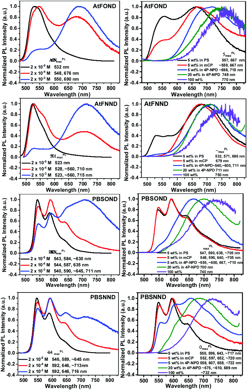 | ||
| Fig. 5 Normalized PL spectra of the studied platinum complexes in CH2Cl2 with varied concentrations (left) and as a solution drop-cast thin film of 5 wt% doped PS, mCP, 4P-NPD, 20 wt% doped 4P-NPD, and the neat film (100 wt%), respectively, where PS is polystyrene, mCP is N,N′-dicarbazolyl-3,5-benzene, and 4P-NPD is N,N′-di-1-napthalenyl-N,N′-diphenyl-[1,1′:4′,1′′:4′′,1′′′-quaterthiophene]-4,4′′′-diamine.21 | ||
At a lower solution concentration of 2 × 10⁻⁵ M, all the platinum complexes show a PL emission with peak wavelengths of 532, 523, 543, and 546 nm for AtFOND, AtFNND, PBSOND, and PBSNND, respectively. First, λPLmax of AtFOND and AtFNND is shorter than that of PBSOND and PBSNND, respectively. Second, the more distinct and stronger vibronic emission bands observed for PBSOND and PBSNND than AtFOND and AtFNND indicate that AtF or PBS dictates the PL spectra. This is consistent with the calculated electron density of the LUMO which is distributed mostly on the AtF or PBS (Fig. 4). The distinct and strong vibronic emission bands observed for PBSOND and PBSNND can be explained by a more extended π-conjugation of the PBS ligand, and hence a more local excitation (LE) characteristic in the emission state. Upon increasing the solution concentration of these platinum complexes to 2 × 10⁻⁴ M and 2 × 10⁻³ M, the emission profiles were broadened due to the emerging emission bands with λPLmax around the deep red or NIR region (Fig. 5). The PL spectra become a mixture of the monomeric emissions (λPLmax of 523–546 nm) and the aggregate/excimer emissions (λPLmax of 675–716 nm). When the solution concentration is increased, the aggregate/excimer emissions are intensified, and the monomeric emissions are weakened. Moreover, while aggregate/excimer emissions are clearly seen at 2 × 10⁻⁴ M for AtFOND and AtFNND, it takes a higher concentration of 2 × 10⁻³ M to develop aggregate/excimer emissions of PBSOND and PBSNND, of which substantial monomeric emissions still remain in the spectra. Such solution PL spectra demonstrate that either AtFOND or AtFNND is more prone to aggregate/excimer formation than PBSOND and PBSNND. In addition to a less tendency to aggregate/excimer formation, emissions associated with a higher LE characteristic may be the reason for higher solution PLQYs of 24% and 36% for PBSOND and PBSNND than 9% and 18% for AtFOND and AtFNND, respectively. Moreover, we have observed that OND-containing platinum complexes always have a lower solution PLQY than that of NND-containing ones, such as 9% and 18% of AtFOND and AtFNND and 24% and 36% of PBSOND and PBSNND, respectively. Such solution PLQY results can be understood by the fact that OND has a higher vibrational freedom than NND because of the phenoxy substituent. Otherwise, the solution PL lifetimes of the four platinum complexes have been measured. They are all in the microsecond regimes; 7.78 μs for AtFOND, 1.17 μs for AtFNND, 1.52 μs for PBSOND, and 0.71 μs for PBSNND (Fig. S15, ESI†). Such PL lifetimes are in general consistent with the solution PLQYs, i.e., the lowest PLQY AtFOND having the longest PL lifetime; the highest PLQY PBSNND having the shortest PL lifetime.
While the formation of aggregates/excimers is concentration-dependent in solution, the host material is decisive for showing deep red or NIR emissions for the four platinum complexes in the solid state, including the doped thin films. The 4P-NPD hosted thin films always promote the aggregate/excimer emissions of the four platinum complexes more than PS or mCP hosted thin films. Nevertheless, as a 100 wt% sample (neat film), all of the four platinum complexes display broad NIR emissions with a λPLmax of 770, 750, 740, and 732 nm for AtFOND, AtFNND, PBSOND, and PBSNND, respectively. All of these NIR emission spectra virtually show no trace of greenish yellow emissions, even though some of these NIR emissions are relatively weak. Similarly, as those in solution, either AtFOND or AtFNND always exhibits more genuine deep red or NIR emissions (with much less intense greenish yellow monomeric emissions) than PBSOND and PBSNND in the doped thin films (Fig. 5). For AtFOND, the long wavelength emissions from the MMLCT due to the short (and hence strong) Pt–Pt contacts may be the main reason. For AtFNND, there are many short molecular contacts (2.44–3.19 Å) found on the methoxy group (OCH3) of AtF (Fig. S16, ESI†). The short contacts involve the oxygen of the OCH3 group, the CH3 of the dimethylamino group, the CH3 of the OCH3 group, the H of the benzene ring (of anisole), the H of the naphthyridine ring, the CH3 of the OCH3 group, the oxygen of ArO–Pt, and the CF3 of the trifluoromethyl group. There is also a π–F contact found in the crystal of AtFNND. These molecular contacts bring the molecules of AtFNND closer in the solid state and in high-concentration (2 × 10⁻³ M) solution, reducing the green emissions of non-aggregated AtFNND. Even though AtFNND has many short molecular contacts that extend the emission wavelength, the solid-state PLQY of AtFNND does not seem to be affected. Probably, many of these short contacts occur in the peripheral structures of AtFNND, not much involving the light-emitting π-conjugated moieties. The solid-state PLQY of AtFNND was determined to be 58%, the highest among the four platinum complexes (Table 1). In sharp contrast, the solid-state PLQY of AtFOND was measured to be less than 10%, the lowest among the four platinum complexes. We may attribute such a low PLQY mainly to the energy gap law, in which the non-radiative pathway dictates the relaxation of the excited state of the deep red or NIR emitters. Otherwise, there is no particularly effective short molecular contact, except for the short and near-vertical Pt–Pt contact (Fig. 1 and Fig. S16, ESI†), which is unique among the four platinum complexes. We surmise that the low PLQY may be due to the MMLCT of AtFOND.
Electrochemical properties and the energy level of HOMO/LUMO
The redox properties of the studied platinum complexes are illustrated by the cyclic voltammograms (CVs) in Fig. 6 and the numerical data are summarized in Table 2.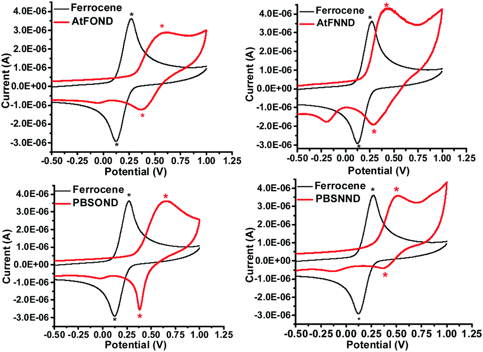 | ||
| Fig. 6 Cyclic voltammograms of AtFOND, AtFNND, PBSOND, BSNND, and ferrocene (reference) in CH2Cl2 (1 mM) in the presence of 0.1 M TBAPF6 at 295 K. | ||
| Pt complexes |
E
oxd1/2
![[thin space (1/6-em)]](https://www.rsc.org/images/entities/char_2009.gif) (V)
(V) |
E HOMO (eV) | λ onset (nm) | E g (eV) | E LUMO (eV) |
|---|---|---|---|---|---|
| a E oxd1/2 (V) refers to [(Epa + Epc)/2], where Epa and Epc are the anodic and cathodic peak potentials, respectively; 0.196 V for Fc+/Fc. b Determined from the onset wavelength of the absorption spectrum. c Estimated from the onset absorption spectrum by the equation Eg = 1240/λonset. d Deduced from the EHOMO and Eg. | |||||
| AtFOND | 0.49 | −5.09 | 462 | 2.68 | −2.41 |
| AtFNND | 0.37 | −4.98 | 460 | 2.69 | −2.29 |
| PBSOND | 0.52 | −5.12 | 466 | 2.65 | −2.47 |
| PBSNND | 0.45 | −5.06 | 461 | 2.69 | −2.37 |
The first oxidation potential, EOXD1/2, exhibits the trend of similarity with the type of ancillary ligands NND and OND, 0.45–0.52 V and 0.61–0.60 V vs. Fc+/Fc, respectively. Such CV results are much consistent with the calculated HOMO electron density (Fig. 4), which distributes primarily on the OND or NND involving coordinated platinum. The anodic signals of AtFOND and PBSOND are at higher potentials than those of AtFNND and PBSNND, which is consistent with the stronger electron-donating strength of the dimethylamino group than that of the phenoxy group. Taking the absorption onset wavelength as the optical energy gap (Eg), the LUMO energy level (ELUMO) of each platinum complex can be calculated based on the CV-determined HOMO energy level (EHOMO) (Table 2). The materials used for device fabrication, including 4P-NPD, mCP, and TPBi, were determined by the same method for EHOMO and ELUMO. They are all aligned and displayed in Fig. 7. Accordingly, singlet excitons can be well confined on the light-emitting layer of the platinum complex in the device of ITO/4P-NPD/mCP/Pt complex/TPBi/LiF/Al.
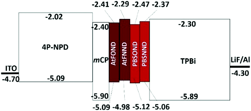 | ||
| Fig. 7 Energy level (eV) alignment of materials involved in the NIR OLEDs. | ||
Electroluminescence properties
The ultrathin light-emitting layers (EMLs) have been demonstrated to enhance the efficiency of non-dopant platinum complex OLEDs.26–28 Accordingly, the ultrathin light-emitting layers of the NIR OLEDs were fabricated by vacuum thermal evaporation as ITO/4P-NPD (40 nm)/mCP (5 nm)/Pt complex (2 nm)/TPBi (45 nm)/LiF (0.8 nm)/Al (100 nm) for AtFOND, AtFNND, PBSOND, and PBSNND, respectively. Data of EL characteristics are summarized in Table 3 and the corresponding device performance is displayed in Fig. 8–10.| NIR emitter | λ ELmax (nm) |
V
turnon
(V) |
EQEb (%) (mA cm−2) | Brightnesscd (cd m−2) |
|---|---|---|---|---|
| a Turn-on voltage is the one at which the luminescence is over 1 cd m−2. b The maximum value of external quantum efficiency (EQE) and the corresponding current density (in parenthesis). c Electroluminescence obtained at maximum values. d Based on human visual perception, cd m−2 is not suitable for genuine NIR OLEDs. | ||||
| AtFOND | 774 | 8.0 | 1.77(6.34) | 220 |
| AtFNND | 744 | 4.0 | 6.54(0.14) | 440 |
| PBSOND | 726 | 5.5 | 3.95(1.43) | 830 |
| PBSNND | 704 | 4.0 | 10.12(2.85) | 1400 |
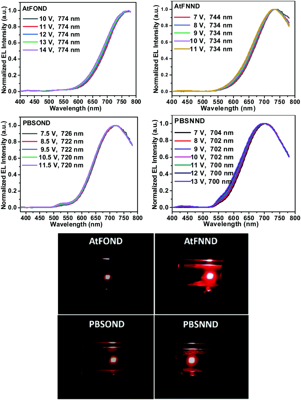 | ||
| Fig. 8 Top figures: intensity normalized EL spectra AtFOND, AtFNND, PBSOND, and PBSNND NIR OLEDs at varied voltage. Bottom figures: corresponding photographs of each device at ∼4–6 V. | ||
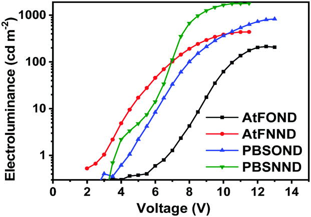 | ||
| Fig. 9 Voltage dependency of electroluminescence (cd m−2) of NIR OLEDs. | ||
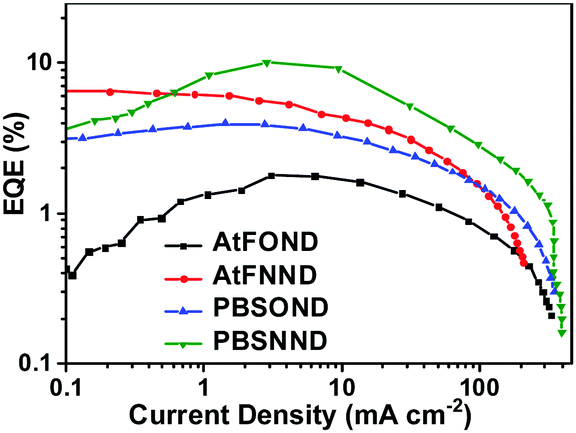 | ||
| Fig. 10 External quantum efficiency as a function of current density. | ||
As shown in the EL spectra in Fig. 8, the λELmax values are 774, 736, 726, and 704 nm for AtFOND, AtFNND, PBSOND, and PBSNND OLEDs, respectively. Since all the λELmax values are >700 nm, these are all NIR OLEDs. All the NIR EL have broad and featureless emission bands, typical for the aggregates/excimers of the platinum complexes. By carefully examining the EL spectra in Fig. 8, there are some minor greenish yellow emissions observed around 500–550 nm and 525–575 nm, which are discernible in PBSOND and PBSNND spectra, respectively. Such greenish yellow emissions are virtually invisible in AtFOND and AtFNND spectra. This is very much similar to the PL spectra of the four platinum complexes in the solid state (Fig. 5). It has been demonstrated from both PL and EL spectra that the aggregates/excimers are more in AtFOND and AtFNND than in PBSOND and PBSNND.
Although a camera is different from a spectroradiometer in terms of brightness and detection sensitivity to NIR, these photographs (Fig. 8 bottom) qualitatively show the relative brightness of each device with a driving voltage of around 4–6 V. While the AtFOND NIR OLED has the least brightness in all driving voltages, the brightest NIR OLED is based on AtFNND instead of PBSNND. Interestingly, such photographs are generally in accordance with the electroluminescence data of the four NIR OLEDs driven at ∼4–6 V (Fig. 9), although the electroluminescence (cd m−2) does not really work for the nearly invisible light from these NIR OLEDs.
Nevertheless, from the photographs shown in Fig. 8, the PBSOND device shows a more orange colour than the other three devices, due to its relatively short NIR EL wavelength (726 nm) and the greenish yellow emission around 520–550 nm, which is most pronounced among the four platinum complexes. Since a conventional camera simply cannot detect NIR, the AtFOND device is the darkest and the most reddish one among the four devices, because of the longest NIR EL wavelength (774 nm) and the longest PL wavelength (750 nm) among the four platinum complexes. The very low PLQY (<10%), either in solution or thin film, is another reason for its feeble PL and EL.
The EQE characteristics of the four NIR OLEDs are plotted as a function of current density in Fig. 10. The figure shows that 1.77%, 6.54%, 3.95%, and 10.12% are the determined maximum EQE values for PBSOND, PBSNND, AtFOND, and AtFNND NIR OLEDs, respectively.
Except for the AtFNND one, the NIR OLEDs exhibit EQE peaked around 1–7 mA cm−2, corresponding to 5–9 V of the OLEDs (Fig. S17, ESI†). Except for the AtFNND one, within a range of 10–100 mA cm−2, the NIR OLEDs exhibit approximately similar EQE roll-off. In addition to a rather similar rising slope of the current density vs. driving voltage (Fig. S17, ESI†), we may infer that the efficiency of electron–hole recombination (charge-balance factor) is about the same for AtFOND, PBSOND, and PBSNND OLEDs, but they are all better than that of AtFNND OLEDs. Since the thickness of the different layers in the four NIR OLEDs is the same, we surmise that such results may be due to the LUMO energy level of AtFNND, which is the highest lying one among the four platinum complexes and is somewhat higher than that of TPBi, the electron transporting material in these NIR OLEDs. Analysing the correlation between the device's EQE and the material's solid state PLQY, the lowest EQE (1.77%) of AtFOND OLEDs can be mainly ascribed to the very low thin film PLQY (<10%) and the very long EL wavelength of 774 nm, of which nearly half of the EL is beyond the detection limit of the spectroradiometer (780 nm of PR-670). A relatively high EQE (6.54%) of AtFNND OLEDs is probably due to its much higher thin film PLQY (58%) and a comparatively shorter EL wavelength of 744 nm. With a reasonable inference, a relatively lower thin film PLQY (52%) of PBSOND can be the reason for its lower EQE (3.95%) of OLEDs. The most surprising EQE is the 10.17% of PBSNND OLEDs. Such an EQE is unusually high, considering the thin film PLQY (ϕPL) of PBSNND, which is only 32% (Table 1). Assuming 100% for both the radiative exciton fraction (ηr) and the efficiency of the electron–hole recombination (γ), lower limits for the light outcoupling efficiency (ηout) can be estimated around 32%, based on an EQE = γ × ηr × ϕPL × ηout. For a conventional OLED with randomly oriented light-emitting molecules and no additional light outcoupling enhancements, the average or regular ηout is ∼20%. Therefore, for such PBSNND NIR OLEDs, an ηout higher than 20% strongly suggests that some PBSNND molecules have special molecular orientation that enhances the ηout of OLEDs.
2D-GIWAXS and molecular orientation
A relatively weak and diffused signal has been identified on the 2D-GIWAXS patterns at the Qz of 0.55 Å−1 (Fig. 11 top). The corresponding d-spacing is calculated to be 11.4 Å (Fig. S18, ESI†). From the X-ray single-crystal data of PBSNND, we have found two correlated distances of 12.0 and 12.2 Å (see Fig. 11 centre). In a unit cell of the PBSNND crystal, molecules of PBSNND are stacked pairwise, two pairs in the upper part and another two pairs in the lower part along the c-axis of the unit cell (see Fig. 11 centre and bottom). | ||
| Fig. 11 Top: 2D-GIWAXS patterns for a vacuum-deposited thin film of PBSNND. Centre: Molecular array in the crystal structure of PBSNND with a ∼90° difference of two viewing angles. Bottom: The schematic display of the centre picture with the labels of MLCT transition dipole, molecular mean plane, and d-spacing. | ||
The projection (∼60–70°) of the molecular transition dipole of the MLCT onto the molecular mean plane (see Fig. 11 bottom) is coincident with the direction of s-polarized waves of the emitting light of the OLEDs, if the molecular mean plane is parallel to the horizontal direction. As such, the light outcoupling of PBSNND OLEDs is enhanced. Therefore, the GIWAXS results together with the single-crystal X-ray structure of PBSNND reasonably explain that the high EQE is due to an enhanced ηout of ∼32%.
Conclusions
In summary, we have successfully synthesized and characterized AtFOND, AtFNND, PBSOND, and PBSNND platinum complexes for PL and EL studies. All four platinum complexes exhibit green to yellow PL in diluted solution but deep red or NIR PL in the solid state. Based on the colours and absorption spectra of the platinum complexes in the solid state, we believe that the MMLCT occurs only for AtFOND among the four platinum complexes. The proposed MMLCT is consistent with the Pt–Pt contacts, which are short (3.39 and 3.88 Å) and almost normal to the molecular planes of the platinum complex evident from the single-crystal X-ray structure. This is probably the reason for AtFOND showing the longest wavelengths of 770 and 774 nm for NIR PL and EL, respectively, in the solid state. However, such MMLCT does not help in the solid-state PLQY or the EQE of the NIR OLEDs. Both PLQY and EQE are the lowest, 9% and 1.8%, among the four platinum complexes. On the other hand, PBSNND shows a relatively high EQE (∼10.1%) of the NIR (λELmax 704 nm) OLEDs, considering its moderate solid-state PLQY of ∼32%. From both 2D-GIWAXS and single-crystal X-ray studies, we have verified that such a high EQE can be attributed to an appropriate molecular alignment of PBSNND that enhances the light outcoupling efficiency to 32%, which is ∼1.6 times higher than ∼20% of most conventional OLEDs.Experimental section
General information
1H and 13C NMR spectra were recorded using Bruker AV-400 MHz and AV-500 MHz NMR Fourier transform spectrometers at room temperature. Elemental analyses were performed at the Instrumentation Center, National Taiwan University. Electron ionization (EI) or fast atom bombardment (FAB) mass spectroscopy (MS) was performed at the Mass Spectroscopic Laboratory, an in-house service of the Institute of Chemistry, Academic Sinica. Solution UV-vis absorption spectra were recorded using a Hewlett-Packard 8453 diode array spectrophotometer. Powder or crystal solid-state absorption spectra were obtained via surface reflection spectroscopy (JASCO V-670 spectrophotometer). Room temperature photoluminescence (PL) spectra of solution, thin film, or powder were recorded using a Hitachi fluorescence spectrophotometer F-7000 or Edinburgh FL920.Solution PLQY was determined using a degassed acetonitrile solution of [Ru(bpy)3](PF6)2 (bpy = 2,2′-bipyridine) as the standard solution (ΦPL = 6.2%).33 The thin film PLQY was determined by the integrating-sphere (Titan Electro-Optics Co., Ltd, Taiwan) method using a monochromated light source (IK5451R-E Kimmon Koha Co., Ltd, Japan) with an excitation wavelength of 442 nm and a Hitachi-F-7000 spectrophotometer as a photodetector. The photoluminescence lifetime was determined on degassed solution samples with an Edinburgh FL920 time-correlated pulsed single-photon-counting instrument.
Redox potentials of the platinum complexes were determined by cyclic voltammetry (CV) using a BAS 100B electrochemical analyser with a scanning rate at 100 mV s−1. FBNNND was dissolved in deoxygenated dry CH2Cl2 with 0.1 M tetrabutylammonium perchlorate as the electrolyte. We used a platinum working electrode and a saturated nonaqueous Ag/AgNO3 reference electrode. Ferrocene was used for potential calibration (the reported potentials are referenced against Ag/Ag+) and for reversibility criteria. The energy level of ferrocene (4.8 V below the vacuum level)29 was used as the reference.
In preparing samples for GIWAXS measurements, samples of PBSNND were deposited on the (100) surface of a silicon wafer. GIWAXS measurements were conducted using the facilities (beamline 17A) of the National Synchrotron Radiation Research Centre (NSRRC) at Hsinchu, Taiwan. The experiments were carried out with an X-ray photon energy of 12.043 keV and a wavelength (λ) of 1.3213 Å. The sample-to-detector distance is 80.00 mm.
X-Ray crystallography studies
Single crystals for the XRD analysis were obtained by slow evaporation of a methanol-dichloromethane solution of the complex at room temperature. Data collection was carried out using a Bruker X8APEX CCD diffractometer at 100 K for the FBNNND single crystal. Mo radiation (λ = 0.71073 Å) was used for both crystals. The unit cell parameters were obtained by a least-squares fit to the automatically centered settings for reflections. Intensity data were collected using the ω/2θ scan mode. Corrections were made for Lorentz and polarization effects. The structures were solved by direct methods SHELX-97.30 All non-hydrogen atoms were located from the difference Fourier maps and were refined by full-matrix least-squares procedures. The position of hydrogen atoms was calculated and located. Calculations and full-matrix least-squares refinements were performed utilizing the WINGX program package31 in the evaluation of the values of R(Fo) for reflections with I > 2σ(I) and Rw(Fo), where R = ∑‖Fo| − |Fc||/∑|Fo| and Rw = [∑{w(Fo2 − Fc2)2}/∑{w(Fo2)2}]1/2. Intensities were corrected for absorption.OLED device fabrication and measurements
OLED devices were fabricated by vacuum–thermal deposition using Sumimoto Cryogenics at a chamber pressure of 10−6 torr. The ITO substrate with a sheet resistance of around 30 Ω sq−1 was purchased from Ruilong Optoelectronics, Taiwan. ITO-coated glass substrates were cleaned with detergent, deionized water, acetone, and isopropanol, followed by oxygen plasma treatment. The current density–voltage characteristics of the devices were measured using a Keithley 2400 source meter, and the device brightness (or electroluminescence, cd m−2) and EL spectra were monitored and recorded with a spectroradiometer (PR-670, Photo Research), respectively.Synthesis and materials
For the materials used in device fabrication, mCP was obtained from Shine Materials Technology Co. CBP,32 TPBI,33and 4P-NPD21 were prepared via the published methods. Except for (AtF)2PtCl and (PBS)2PtCl, these synthesized materials were purified by vacuum train sublimation before use in the device fabrication process. The general synthesis methodology of the corresponding monometallic platinum complex precursors, (AtF)2PtCl and (PBS)2PtCl, is reported herein. Including the much improved synthesis of OPhONDH, the synthesis and characterization of AtFOND, AtFNND, PBSOND, and PBSNND are shown below.:2) and the last yellow band was collected and dried to yield a yellow solid. The product was isolated as a golden yellow solid (0.31 g, 0.48 mmol, 92%). The single crystals for the X-ray diffraction structure analysis were obtained by slow evaporation of methanol–dichloromethane solution of AtFNND at room temperature. 1H NMR (400 MHz, CDCl3, δ): 9.55 (S, 1H), 8.61(d, 1H, J = 6.4 Hz), 8.28 (d, 1H, J = 5.2 Hz), 7.94 (d, 1H, J = 8.2 Hz), 7.58 (d, 1H, J = 8.4 Hz), 7.50 (d, 1H, J = 8.5 Hz), 7.05 (S, 1H), 6.87 (d, 1H, J = 5.3 Hz), 6.70 (d, 1H, J = 8.4 Hz), 6.54 (d, 1H, J = 6.4 Hz), 3.93 (S, 3H), 3.57 (S, 6H)). 13C NMR (125 MHz, CDCl3, δ): 173.27, 169.79, 161.42, 154.95, 149.01, 147.21, 146.53, 146.50, 146.15, 143.02, 139.14, 137.54, 135.02, 126.95, 124.11, 123.44, 123.17, 122.90, 121.95, 118.37, 117.35, 112.39, 108.30, 105.00.
FAB-HRMS: calcld 635.1108, m/z = 636.1194 (M + H+). Anal. found (calcd) for C23H19F3N4O2Pt C 43.44(43.47), H 3.11(3.01), N 8.82(8.82).
:1) and the last yellow band was collected. The product was isolated as a red solid (0.09 g, 0.13 mmol, 62%). 1H NMR (400 MHz, CDCl3, δ): 9.46 (d, 1H, J = 8.4 Hz), 8.90 (d, 1H, J = 5.9 Hz), 8.58 (d, 1H, J = 5.5 Hz), 7.81 (d, 1H, J = 7.9 Hz), 7.65 (t, 1H, J = 7.9 Hz), 7.44–7.53 (m, 5H), 7.37 (d, 1H, J = 7.0 Hz), 7.31 (d, 2H, J = 7.6 Hz), 7.13 (t, 2H, J = 6.8 Hz), 7.01 (d, 1H, J = 5.4 Hz), 6.71 (d, 1H, J = 6 Hz). 13C NMR (125 MHz, CDCl3, δ): 107.06, 113.46, 122.06, 123.59, 126.18, 128.07, 130.96, 137.80, 138.59, 142.09, 147.14, 150.72, 153.73, 163.77, 175.08, 181.35. FAB-HRMS: calcld: 642.0689, m/z = 643.0772 (M + H+). Anal. found (calcd) for C27H17N3O2PtS C 47.19(50.47), H 2.56(2.67), N 6.24(6.54).
Conflicts of interest
There are no conflicts to declare.Acknowledgements
The authors thank the Ministry of Science and Technology (MOST 106-2113-M-001-016-MY3) of Taiwan for financial support. The International Graduate Program (TIGP) of Academia Sinica, Institute of Chemistry of Academia Sinica, and National Yang Ming Chiao Tung University are acknowledged.References
- T. Weil, T. Vosch, J. Hofkens, K. Peneva and K. Müllen, Angew. Chem., Int. Ed., 2010, 49, 9068–9093 CrossRef CAS.
- Z. Guo, S. Park, J. Yoon and I. Shin, Chem. Soc. Rev., 2014, 43, 16–29 RSC.
- E. C. Lee, H. Jung and D. Kim, Sensors, 2011, 11, 2319–2333 CrossRef CAS.
- L. Maggini, I. Cabrera, A. Ruiz-Carretero, E. A. Prasetyanto, E. Robinet and L. De Cola, Nanoscale, 2016, 8, 7240–7247 RSC.
- B. N. G. Giepmans, S. R. Adams, M. H. Ellisman and R. Y. Tsien, Science, 2006, 312, 217–224 CrossRef CAS PubMed.
- J. L. Liu, J. Q. Zhang, Z. L. Tang, Y. Zhuo, Y. Q. Chai and R. Yuan, Chem. Sci., 2019, 10, 4497–4501 RSC.
- A. Zampetti, A. Minotto and F. Cacialli, Adv. Funct. Mater., 2019, 29, 1807623 CrossRef.
- X. Du, J. Qi, Z. Zhang, D. Ma and Z. Y. Wang, Chem. Mater., 2012, 24, 2178–2185 CrossRef CAS.
- Y. Yuan, J. Liao, S. Ni, A. K.-Y. Jen, C. Lee and Y. Chi, Adv. Funct. Mater., 2019, 1906738 Search PubMed.
- J. V. Caspar, E. M. Kober, B. P. Sullivan and T. J. Meyer, J. Am. Chem. Soc., 1982, 104, 630–632 CrossRef CAS.
- F. C. Spano and C. Silva, Annu. Rev. Phys. Chem., 2014, 65, 477–500 CrossRef CAS PubMed.
- M. Ibrahim-Ouali and F. Dumur, Molecules, 2019, 24, 1412 CrossRef CAS PubMed.
- X. Yang, H. Guo, X. Xu, Y. Sun, G. Zhou, W. Ma and Z. Wu, Adv. Sci., 2019, 6, 1801930 CrossRef.
- K. R. Graham, Y. Yang, J. R. Sommer, A. H. Shelton, K. S. Schanze, J. Xue and J. R. Reynolds, Chem. Mater., 2011, 23, 5305–5312 CrossRef CAS.
- M. A. Baldo and S. R. Forrest, Phys. Rev. B: Condens. Matter Mater. Phys., 2000, 62, 958–966 Search PubMed.
- Q. Wang, I. W. H. Oswald, X. Yang, G. Zhou, H. Jia, Q. Qiao, Y. Chen, J. Hoshikawa-halbert and B. E. Gnade, Adv. Mater., 2014, 26, 8107–8113 CrossRef CAS PubMed.
- P. Ganesan, W. Hung, J. Tso, C. Ko, T. Wang, P. Chen, H. Hsu, S. Liu, G. Lee, P. Chou, A. K. Jen and Y. Chi, Adv. Funct. Mater., 2019, 29, 1900923 CrossRef.
- K. Tuong, Ly, R. W. Chen-Cheng, H. W. Lin, Y. J. Shiau, S. H. Liu, P. T. Chou, C. S. Tsao, Y. C. Huang and Y. Chi, Nat. Photonics, 2017, 11, 63–68 CrossRef.
- A. Poloek, C. W. Lin, C.-T. Chen and C.-T. Chen, J. Mater. Chem. C, 2014, 2, 10343–10356 RSC.
- A. Poloek, C. Wang, Y. T. Chang, C. W. Lin, C.-T. Chen and C.-T. Chen, J. Mater. Chem. C, 2015, 3, 11163–11177 RSC.
- A. Poloek, C.-T. Chen and C.-T. Chen, J. Mater. Chem. C, 2014, 2, 1376–1380 RSC.
- S. Li, X. Li, Q. Li, Q. Yuan, X. Shi and Q. Xu, Green Chem., 2015, 17, 3260–3265 RSC.
- S. Chen, G. Tan, W. Wong and H. Kwok, Adv. Funct. Mater., 2011, 21, 3785–3793 CrossRef CAS.
- Crystal data for AtFOND: C27H18F3N3O3Pt: Fw = 684.53, orthorhombic, Pbcn, Z = 8, F(000) = 2640. Cell dimendions: a = 7.0583(2) Å, b = 29.4421(9) Å, c = 21.6515(7) Å, α = 90°, β = 90°, γ = 90°, V = 4499.4(2) Å3, 2θ max = 50.5°, rcacld = 2.021 mg m−3. Of 96170 reflections, 4967 were independence, 335 parameters, R(Fo) = 0.0193 (for reflections with I > 2s(I)), Rw(Fo) = 0.0436 (for reflections with I > 2s(I)). The GoF on F2 was equal 1.103. AtFNND: C23H19F3N4OPt: Fw = 635.51, triclinic, P, Z = 4, F(000) = 1224. Cell dimendions: a = 12.0617(16) Å, b = 13.1230(18) Å, c = 14.549(2) Å, α = 69.047(4)°, β = 78.618(4)°, γ = 74.686(4)°, V = 2060.6(5) Å3, 2θ
![[thin space (1/6-em)]](https://www.rsc.org/images/entities/i_char_2009.gif) max = 50.5°, rcacld = 2.049 mg m−3. Of 79065 reflections, 9091 were independence, 599 parameters, R(Fo) = 0.0314 (for reflections with I > 2s(I)), Rw(Fo) = 0.0551 (for reflections with I > 2s(I)). The GoF on F2 was equal 1.030. PBSNND: C23H18N4OPtS: Fw = 593.56, orthorhombic, Pbca, Z = 8, F(000) = 2288. Cell dimendions: a = 21.8970(5) Å, b = 7.1898(2) Å, c = 24.3791(5) Å, α = 90°, β = 90°, γ = 90°, V = 3838.12(16) Å3, 2θmax = 50.5°, rcacld = 2.054 mg m−3. Of 60913 reflections, 4223 were independence, 273 parameters, R(Fo) = 0.0153 (for reflections with I > 2s(I)), Rw(Fo) = 0.0360 (for reflections with I > 2s(I)). The GoF on F2 was equal 1.054. CCDC 2009562 (AtFOND), 2009563 (AtFNND), and 2009796 (PBSNND).
max = 50.5°, rcacld = 2.049 mg m−3. Of 79065 reflections, 9091 were independence, 599 parameters, R(Fo) = 0.0314 (for reflections with I > 2s(I)), Rw(Fo) = 0.0551 (for reflections with I > 2s(I)). The GoF on F2 was equal 1.030. PBSNND: C23H18N4OPtS: Fw = 593.56, orthorhombic, Pbca, Z = 8, F(000) = 2288. Cell dimendions: a = 21.8970(5) Å, b = 7.1898(2) Å, c = 24.3791(5) Å, α = 90°, β = 90°, γ = 90°, V = 3838.12(16) Å3, 2θmax = 50.5°, rcacld = 2.054 mg m−3. Of 60913 reflections, 4223 were independence, 273 parameters, R(Fo) = 0.0153 (for reflections with I > 2s(I)), Rw(Fo) = 0.0360 (for reflections with I > 2s(I)). The GoF on F2 was equal 1.054. CCDC 2009562 (AtFOND), 2009563 (AtFNND), and 2009796 (PBSNND). - M. S. Lowry, W. R. Hudson, R. A. Pascal and S. Bernhard, J. Am. Chem. Soc., 2004, 126, 14129–14135 CrossRef CAS PubMed.
- X. Yang, F. I. Wu, H. Haverinen, J. Li, C. H. Cheng and G. E. Jabbour, J. Appl. Phys. Lett., 2011, 98, 033302 CrossRef.
- X. Yang and G. E. Jabbour, J. Mater. Chem. C, 2013, 1, 4663–4666 RSC.
- H. T. Kidanu and C.-T. Chen, J. Mater. Chem. C, 2021, 9, 1410–1418 RSC.
- K. Araki, L. Angnes and H. E. Toma, Adv. Mater., 1995, 7, 554–559 CrossRef CAS.
- G. M. Sheldrick, SHELXL-97, University of Gottingen, Germany, 1977 Search PubMed.
- L. J. Farrugia, J. Appl. Crystallogr., 1999, 32, 837–838 CrossRef CAS.
- P. J. Low, M. A. J. Paterson, D. S. Yufit, J. A. K. Howard, J. C. Cherryman, D. R. Tackley, R. Brook and B. Brown, J. Mater. Chem., 2005, 15, 2304–2315 RSC.
- J. Shi, C. W. Tang and C. H. Chen, US Pat., 5645948, 1997 Search PubMed.
- S. Barlow, T. V. Timofeeva, J. Li, S. R. Marder, K. Y. Suponitsky and J.-Y. Cho, J. Organomet. Chem., 2005, 690, 4090–4093 CrossRef.
- J. A. Lowe, O. J. Stacey, P. N. Horton, S. J. Coles and S. J. A. Pope, J. Organomet. Chem., 2016, 805, 87–93 CrossRef CAS.
Footnote |
| † Electronic supplementary information (ESI) available: NMR and MASS spectra, decay profile of the PL, molecular interaction in the crystal, theoretical studies, voltage dependent current density, Qz of 1D-GIWAXS, and CCDC 2009562, 2009563 and 2009796. For ESI and crystallographic data in CIF or other electronic format see DOI: 10.1039/d1ma00141h |
| This journal is © The Royal Society of Chemistry 2021 |