
 Open Access Article
 This Open Access Article is licensed under a
 Creative Commons Attribution 3.0 Unported Licence
All-fiber pyro- and piezo-electric nanogenerator for IoT based self-powered health-care monitoring†
Biswajit
Mahanty
 ab,
Sujoy Kumar
Ghosh‡
a,
Kuntal
Maity
a,
Krittish
Roy
a,
Subrata
Sarkar
a and
Dipankar
Mandal
*c
ab,
Sujoy Kumar
Ghosh‡
a,
Kuntal
Maity
a,
Krittish
Roy
a,
Subrata
Sarkar
a and
Dipankar
Mandal
*c
aDepartment of Physics, Jadavpur University, Kolkata 700032, India
bDepartment of Electronics & Communication Engineering, Ramgarh Engineering College, Murbanda, Ramgarh, Jharkhand 825101, India
cInstitute of Nano Science and Technology, Knowledge City, Sector 81, Mohali 140306, India. E-mail: dmandal@inst.ac.in; dpkrmandal@gmail.com; Fax: +91-172-2211074; Tel: +91-172-2297000
First published on 12th May 2021
Abstract
In this work, an all-fiber pyro- and piezo-electric nanogenerator (PPNG) is designed using multiwall carbon nanotube (MWCNT) doped poly(vinylidene fluoride) (PVDF) electrospun nanofibers as the active layer and an interlocked conducting micro-fiber based electrode for converting both thermal and mechanical energies into useful electrical power. The PPNG generates high electrical throughput (output voltage ∼35 V, maximum power density ∼34 μW cm−2 and power conversion efficiency (ηpiezo) ∼ 19.3%) with an ultra-fast response time of ∼10 ms. Owing to the higher piezoelectric charge co-efficient (|d33| ∼ 51.3 pC N−1) and figure of merit (FoM ≈ 5.95 × 10⁻¹¹ Pa−1) of PVDF–MWCNT nanofibers in comparison to the neat PVDF nanofibers (|d33| ∼ 22 pC N−1 and FoM ≈ 9.7 × 10⁻¹² Pa−1) the PPNG operates a range of consumer electronic components such as capacitors and light emitting diodes. Furthermore, the electroactive phase content (∼87%) is improved in the active layer due to the interfacial interaction between the surface charges at from the π-electron cloud of the MWCNT and –CH2– dipoles of the PVDF chain. Additionally, the PVDF–MWCNT nanofibers possess fifteen times higher pyroelectric coefficient (∼60 nC m−2 K−1) compared to that of neat PVDF nanofibers (4 nC m−2 K−1). As a result, the PPNG is capable of converting very large temperature fluctuations (ΔT ∼ 14.30 K) to electrical energy (such as the open-circuit voltage of 250 mV and a short-circuit current of 83 pA). Besides this, it is capable of detecting very low-level thermal fluctuations (as low as ΔT ∼ 5.4 K) with responsivity of ∼1.48 s and possesses very high mechano-sensitivity (∼7.5 V kPa−1) which makes it feasible for use as a biomedical sensor since the body temperature and bio-mechanical signals (such as breathing temperature, pulse rate, vocal cord vibrations, coughing sound, and so on) have an immense signature of health conditions. As a proof-of-concept, the all-fiber PPNG is employed as a biomedical sensor by integrating with the Internet of Things (IoT) based human health care monitoring system as well as for remote care of infectious diseases (e.g., applicable for pneumonia, COVID-19) by transferring the pulse response, body temperature, coughing and laughing response wirelessly to a smartphone.
1. Introduction
Recently, the “Internet of Things (IoT)” has gained considerable attention in numerous applications in remote health care monitoring systems, especially in infectious diseases (e.g. pneumonia, COVID-19).1–3 An ultra-sensitive pressure–temperature dual functional pressure sensor is the main component of state-of-the-art IoT based remote health care systems. It is used to collect the physiological signals from different parts of our body and behaves as a transducer by converting the applied force and temperature fluctuations into an electrical signal, or other perceived signal output.4,5 These sensors can be adhered to our regularly used textiles or may be attached on the human skin for real-time monitoring of human health, activities and physiological signal measurements. In real-life application the textile based self-powered sensor is an ideal candidate as it is ultra-flexible, light weight and conformable to any surface of the body as well as because no external bias is required to operate it. In this scenario, piezoelectric and pyroelectric materials are ideal candidates as they require no external bias to operate. Conventionally, very highly sensitive pressure sensors are operated by a piezo-resistive and capacitive mechanism which needs an external bias electric field. This essential requirement restricts the convenient utilization and integration of the sensors with wireless communication systems. In terms of the mechanical energy harvesting approach triboelectric nanogenerators are ideal candidates for higher output power generation,6 but piezoelectric nanogenerators are essential devices for higher stability and lower pressure sensing applications, specifically physiological signal monitoring. To date, despite their brittle (low toughness) and rigid (high stiffness) nature, a large number of inorganic and lead based materials have been applied to fabricate piezo- and pyro-electric nanogenerators.7 In contrast the organic polymer based piezoelectric and pyroelectric materials are of particular interest towards electronic skin because of their high compliance and flexibility, light weight nature and bio-compatibility. PVDF is one of the most favorable ferroelectric polymer classes.8 Among the five crystallographic forms (α-, β-, γ-, δ- and ε), the β-phase is the most suitable form for piezoelectric and pyroelectric properties of PVDF. There are several well-known methods available to attain high β-phase content, including the electrical poling method, where a high electric field (typically 100 kV mm−1) is applied.9 The challenges with electrical poling strategies can be overcome using the electrospinning method where the introduction of the β-phase and the in situ alignment of dipoles occur concurrently due to the nano-confinement effect in electrospun nanofibers. In addition, the electrospinning process enables the preparation of flexible and ultra-light piezoelectric membranes, making them more applicable in flexible self-powered sensors for human health detection or monitoring. However, the performance of electrospun PVDF nanofibers remains relatively low due to the lack of suitable device engineering, which leads to a small output power when used in energy harvesting applications. In this scenario, a large number of researchers have used different types of filler, especially MWCNTs, to improve the performance or efficiency of PVDF electrospun fiber based nanogenerators.10–12 The addition of MWCNTs to PVDF significantly improved the output response of nanogenerators. From a material point of view, the feasibility of MWCNTs as a filler material lies in its structural appearance, which is made up of different coaxial cylinders composed of a single layer of graphene around the cylindrical inner hole. It is noticed that a huge number of articles have been reported on PVDF nanofiber based nanogenerators, but a temperature–pressure dual functional all-fiber based wearable sensor was hardly reported. The metal foil or metal-coated thin film-based electrodes for charge collection both have limitations with respect to the device lifetime under the prolonged cyclic stress.13 There were a few more limitations found which include the poor fatigue resistance causing early failure of the metal foil and a huge mismatch of the Young's modulus of the metal coated electrode and the active thin film. However, due to the prolonged period of application, loss of mechanical integrity and electric connectivity occurred. Now all these issues can be avoided by adopting an efficient and durable all-fiber nanogenerator of a three-layered structure where both piezo- and pyro-electric active constituent and electrodes are composed of adaptable and soft fiber arrays.In this work, a notable enhancement of the electroactive phase content in the electrospun PVDF nanofiber has been attained by the synergistic effect of interfacial interactions of MWCNTs with the PVDF chain and further mechanical stretching in the course of collection of the fiber by the high speed rotating collector. As a result a very high piezoelectric/pyroelectric coefficient, figure of merit and energy harvesting output power with high power conversion efficiency have been achieved. A highly sensitive all-fiber nanogenerator is designed with PVDF–MWCNT nanofibers which could capture very low level temperature fluctuations and possesses very high pressure sensitivity. With such effective performance, an IoT based wireless health care system is developed through which the physiological signals can be transferred to a smart phone, indicating a promising way of real time remote health care monitoring.
2. Results and discussion
All-fiber nanogenerator/sensor fabrication strategy
The copper (Cu)–nickel (Ni) plated interlocked micro-fiber based polyester fabric was used as the top and bottom electrodes to fabricate the piezoelectric and pyroelectric nanogenerator (PPNG). Conducting copper wires were attached on both electrodes and finally the three layered structure PPNG was covered with a PDMS layer. The schematic diagram of the all-fiber nanogenerator is shown in Fig. 1a. The generated electrospun nanofibers are shown in Fig. 1a(i). The all-fiber nanogenerator consists of PVDF–MWCNT electrospun nanofibers (Fig. 1a(ii)) sandwiched between interlocked micro-fiber arrays of conducting fabric as charge collecting electrodes (Fig. 1a(iii)). The device was further encapsulated with PDMS for protection from the environment and to ensure a compact structure of the device. The diameter of the interlocked micro-fiber of the conducting electrode was 15 μm. The excellent flexibility and conformability of the generated electrospun nanofibers to the human finger is shown in Fig. 1b. The digital image of the fabricated original PPNG is shown in Fig. S1 (ESI†). Thus, in the fabricated PPNG active piezoelectric and pyroelectric component and the electrodes all are composed of fibers.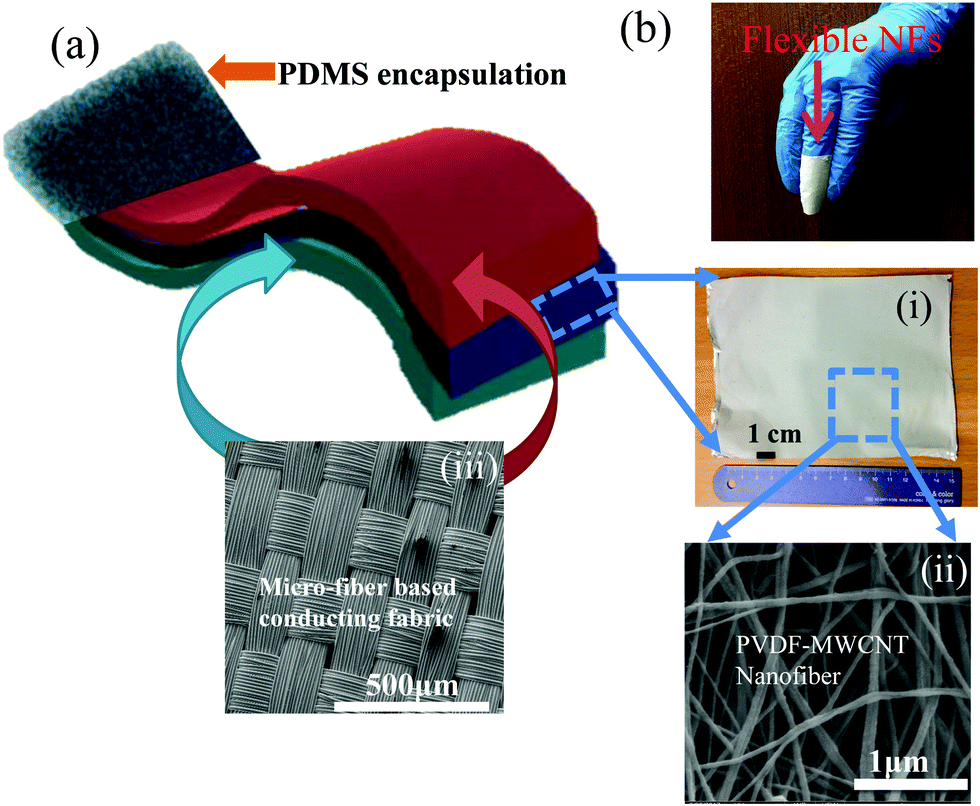 | ||
| Fig. 1 (a) Schematic of the all-fiber PPNG comprising of (i) a large area PVDF–MWCNT nanofiber mat (8 cm × 7 cm). (ii) FESEM images of the PVDF–MWCNT nanofiber and (iii) micro-fiber based conducting electrode. (b) The excellent flexibility and conformability of PVDF–MWCNT electrospun nanofibers is shown by wrapping them on a human finger. | ||
Structural and electrical properties
The FE-SEM image with the corresponding histogram profiles of PVDF-MWCNT nanofibers is shown in Fig. 2a. The fiber diameter distribution plot is presented in the inset of Fig. 2a. It is observed that randomly oriented nanofibers are formed and the average diameter of the fibers ranges from 40 to 165 nm, with the maximum number of fibers possessing a diameter of ∼85 nm. During the formation of fibers i.e., electrospinning process, the molecular dipoles of PVDF nanofibers are preferentially oriented in the out-of-plane direction since the nanofibers and polymer chains are aligned within the plane of the collector.14 This is due to the simultaneous application of the electric field and mechanical stretching leading to polymer jet elongation, whipping and in situ poling.15 During electrospinning of the MWCNT mixed PVDF solution, the conductive MWCNTs can produce inductive charges on their surface when the external electric field is applied, which results in a greater Coulomb force during the electrospinning process. This effect helps to improve the piezoelectric and pyroelectric properties of electrospun PVDF–MWCNT nanofibers due to the excellent interfacial interaction between the PVDF polymer chain and MWCNT surface charges the nanoscopic scale. Therefore, a synergistic effect occurred between interfacial interaction and mechanical stretching during the collection of fibers by a high speed rotating collector during crystallization of fibers. As a result, the content of electroactive β-phase was much higher in PVDF–MWCNT nanofibers than in the neat (pure) PVDF nanofibers and this is evident from the FT-IR plot (see Fig. 2b). The FT-IR spectra of PVDF–MWCNT and neat PVDF nanofibers are shown in Fig. 2b, in the region of 1600–400 cm−1. Evidently the neat PVDF nanofibers contain the α-phase (non-polar) (see the vibrational band at 762 cm−1 in the inset of Fig. 2b), and β- and γ-(polar) phases (vibrational bands at 1277 and 1234 cm−1 respectively).9,16 However, the PVDF-MWCNT nanofibers contain only polar β- and γ-phases and no α-phase peak is observed in the spectrum, as seen in the inset of Fig. 2b. This implies the conversion of non-polar phases (α-phase) into polar phases (β- and γ-phases) in PVDF-MWCNT nanofibers in comparison to neat PVDF nanofibers by the electrospinning process. Eventually, it is found that both the nanofibers having 841 cm−1 vibrational band, which presenting the coexistence of β- and γ-phases.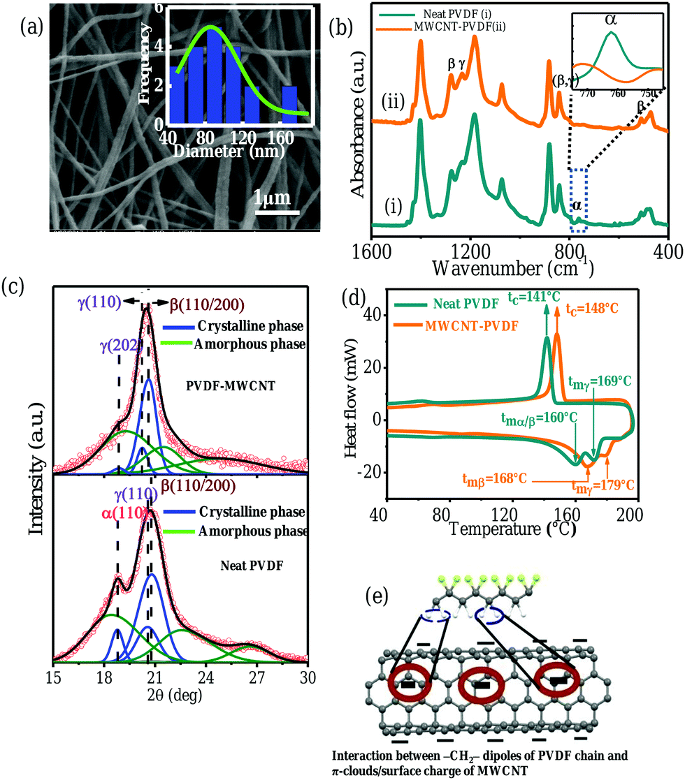 | ||
| Fig. 2 (a) FE-SEM image and the corresponding fiber diameter distribution plot in the inset, (b) FT-IR spectra of PVDF-MWCNT and neat PVDF nanofibers in the region of 1600–400 cm−1, (c) XRD patterns and their curve deconvolution of PVDF–MWCNT nanofibers and neat PVDF nanofibers, (d) DSC thermograms of PVDF–MWCNT and neat PVDF nanofibers. (e) Schematic of the interaction between –CH2– dipoles of the PVDF chain and π-electron clouds/surface charges of MWCNTs. | ||
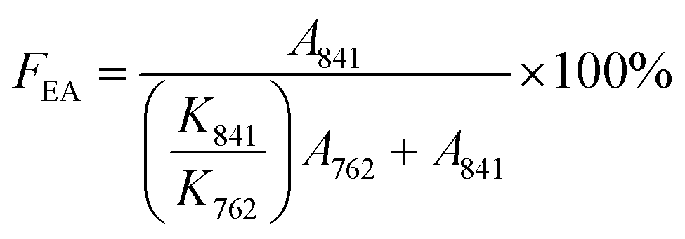
Assuming that the infrared absorption follows the Beer–Lambert law, the relative proportion of electroactive β- and γ-phases (defined as FEA) is calculated using eqn (1) as
 | (1) |
Additionally, Fig. 2c shows the curve-deconvoluted XRD patterns of the PVDF–MWCNT and neat PVDF nanofibers. As evident, the diffraction peak at 2θ of 19.2° in neat PVDF nanofibers corresponds to the reflection of the α-crystalline phase (110) and 2θ of 20.8° corresponds to the cumulative peak of the β- and γ-crystalline phase (110/200). Although the electrospinning technique is a very good option to induce all-trans configuration (β-phase) in the PVDF crystal structure, the α-phase still exists in the neat PVDF nanofibers, which can be understood from the XRD and FT-IR analysis. The α-crystalline phase is fully diminished in the composite fibers (Fig. 2b and c), which is due to the addition of MWCNTs in the PVDF matrix. The conversion of the non-polar to polar phase occurs due to two factors:
1. Simultaneous poling and stretching during the electrospinning process.
2. The interfacial interaction present between the surface charge/π-cloud of MWCNTs and –CH2– dipoles of the PVDF chain.
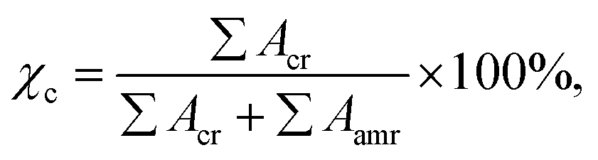
The degree of crystallinity (χc) is calculated from
 | (2) |
It can be seen that both the melting peaks (tm) of the two types of nanofibers indicate the existence of β-and γ-phases. The endothermic melting peak of the β- and γ-phases is found in PVDF–MWCNT nanofibers at ∼168 °C and ∼179 °C respectively.16,19–21 For the neat PVDF nanofibers, it is found that the melting peak of α/β-phases is at ∼160 °C.16,19–21 As a result, both β- and γ-phases are considered more stable thermally in the PVDF–MWCNT nanofibers with respect to neat PVDF nanofibers. As a consequence, the crystallization temperature (tc) of PVDF–MWCNT nanofibers (∼148 °C) was also enhanced with respect to the neat PVDF (∼141 °C). This is due to MWCNTs acting as a nucleating agent and hindering the movement of polymer chain segments. Moreover, the induced polar β-phase is stabilised during rapid crystallization and not relaxed back to the non-polar α-phase via thermal motion. As a result, the formation of the crystalline β-phase is irreversible in the PVDF–MWCNT nanofibers and not relaxed back to the α-phase via thermal motion.22 It is noteworthy that in the case of the free standing film sample containing the gamma phase, the melting point is at a relatively much higher side.19 In contrast, the electrospun samples act a bit differently which may be because of air-permeable spongy like behaviour that leads to lower melting temperature compared to that of the right film specimen. In addition, from the DSC data the total degree of crystallinity (χct) of the nanofibers was calculated using
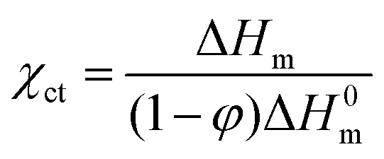 | (3) |
Pyroelectric energy harvesting
The harvesting of thermal energy from the all-fiber PPNG is obtained by the pyroelectric effect. The temperature fluctuations are maintained using an IR light source placed on the top surface of the PPNG. The pyroelectric energy harvesting performance of the PPNG is shown in Fig. 3 in terms of the measurement of the open circuit voltage (Voc) under different temperature fluctuations of ΔT ∼ 14.3 K (Fig. 3a) and ΔT ∼ 5.4 K (Fig. 3c) as well as the corresponding short circuit current (Isc) with the temperature gradient (dT/dt) in Fig. 3b and d respectively. It is noteworthy to mention that Isc and Voc are 71 pA and 250 mV (approx.) respectively when ΔT ∼ 14.3 K and dT/dt = 2.15 K s−1 under the temperature switching frequency of 0.01 Hz which is much higher than that of the device made from neat PVDF.24 When the switching frequency changes from 0.01 Hz to 0.1 Hz (ΔT ∼ 5.4 K and dT/dt = 1.72 K s−1) Isc and Voc are 83 pA and 135 mV (approx.) respectively as shown in Fig. 3c and d. The short circuit current Isc can be expressed as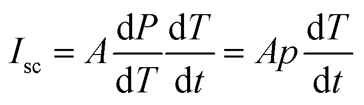 | (4) |
 is the rate of temperature change (K s−1) and p is the pyroelectric coefficient (nC m−2 K−1).24–26 This enhancement of Isc was accomplished by a thermally induced piezoelectric coupling effect, as the output performance is proportional to ΔT and dT/dt. The available maximum power density (P) of the PPNG is estimated to be ∼12 nW m−2 when the temperature difference between the electrodes is ΔT ∼ 14.3 K. Using eqn (4), the estimated pyroelectric coefficient (p) of the PPNG is 60 nC m−2 K−1, which is almost fifteen times higher than that of the neat PVDF fiber (4 nC m−2 K−1).24Isc and Voc are found to be linearly proportional to dT/dt and ΔT profiles respectively (Fig. 3e and f) in agreement with the theoretical paradigm. These linear characteristics suggest the potential of the PPNG as a self-powered pyroelectric temperature sensor for future practical applications especially in various infectious diseases. Fig. 3g shows the expanded view of the positive current pulse signal of the rectangular red dotted marked cycle of Fig. 3b. It has been observed that the current increases from zero to its peak value within ∼1.48 s in the positive side while in the negative side it takes ∼1.54 s (inset of Fig. 3g). As soon as the heat source is removed, the positive output current is returned back to a minimum value. Fig. 3h represents the “Iscvs. T” curve where it is observed that the current pulse is decreasing exponentially with a time constant value of 2.60 s. This decaying process corresponds to a temperature reduction of the PPNG. The value of the reset time for the PPNG is estimated as the time required to recover to 1/e or (37%) and is approximately 2.60 s. So, it is noteworthy to mention that the PPNG can be used as a good temperature sensor due to its reduced response time and reset time compared to that of the previously reported thermoelectric sensor.27
 | ||
| Fig. 3 Measurement of output open circuit voltage under temperature fluctuations of (a) ΔT ∼ 14.3 K and (c) ΔT ∼ 5.4 K and the corresponding output short circuit current with the variation of rate of temperature (dT/dt) in (b) and (d) respectively. (e) Variation in output current as a function of rate of change in temperature. (f) Output voltage as a function of temperature difference. (g) The expanded view of the positive output current signal of the marked cycle in (b) and the negative pulse signal in the inset. (h) The expanded view of the current (Isc) vs. time (T) curve of the marked cycle in (b) when the source of heat was removed. | ||
The better pyroelectric performance of PVDF–MWCNT nanofibers is ascribed to the infrared transparency (∼5%)28 and improved absorption property of electromagnetic energy by MWCNTs which generates rapid heating in the nanofibers. When the device is exposed to heat (i.e. dT/dt > 0) the short circuit current (Isc) reaches its positive peak and a negative peak through the cooling process (i.e. dT/dt < 0). This happens because of the decrement of the degree of spontaneous polarization at the time of the heating process, which forces the surface charges to flow within the two polar surfaces. The current flows in the opposite direction because of the attractive force of the free charges to the polar surfaces when the device is subsequently cooled.25 From the output voltage and current graph, it is very evident that the output current follows the temperature gradient profile (as Isc ∝ dT/dt) and the output voltage follows the thermal fluctuation (Voc ∝ ΔT) profile. A summary or comparison of device materials, electrode materials, output performance and pyroelectric coefficient of the PPNG with the reported pyroelectric nanogenerators is given in Table S1 (ESI†). It has been observed that in spite of the lower pyroelectric co-efficient of PVDF–MWCNT nanofibers in many cases the output performance, in terms of output voltage and current, is much higher than that of previous reports.
Piezoelectric energy harvesting
To demonstrate the application of the materials, we have fabricated a PVDF-MWCNT based all-fiber nanogenerator/energy harvester (PPNG). Electrical characterization of the PPNG is shown in Fig. 4a–f and repetitive finger striking over the PPNG surface from a height of 5 cm is undertaken with different magnitudes of compressive stress (σa = 2, 4 and 6 kPa), as shown in Fig. 4a. As a result, the PPNG generates open circuit output voltages (Voc) of 11, 20 and 35 V respectively, showing more than 90% improvement in output voltage under a compressive stress σa = 2 kPa over the neat PVDF based nanogenerator (see Fig. S2, ESI†). In addition, the press and release response of the single peak from the PPNG is shown in the right lower inset of Fig. 4a and it is found that the PPNG shows an ultra-fast response time of ∼10 ms. It is important to note that the generated Voc varies almost linearly with the increase of σa (right upper inset of Fig. 4a) which is consistent with the piezoelectric theory. As a result, the mechanosensitivity (SM), where SM = (ΔVoc/ΔF), has been determined to quantify the dynamic mechanical stimuli sensing ability where ΔVoc and ΔF are the differences of the output voltage and force respectively.12,22 The average mechano-sensitivity (SM) of the PPNG is ∼7.5 V kPa−1, which is higher than that of the earlier published high performance nanogenerators.18,24,29–31 A detailed comparison plot of piezoelectric mechano-sensitivity with cited references is provided in Fig. 4b.32–37 The horizontal line is used to guide the eyes whereas the vertical line indicates the improved value of this work. It is very prominent that the sensitivity of our device is much improved over previous research and is very much suitable for healthcare monitoring applications where sensitivity is the major factor. The superior energy harvesting performance of the PPNG is attributed to the higher piezoelectric charge coefficient d33 = g33ε0εr = 51.3 pC N−1, where g33 is the piezoelectric voltage coefficient, ε0 is the permittivity of free space (∼8.85 × 10⁻¹² F m−1) and εr ≈ 5 at 1 kHz is the dielectric constant of PVDF–MWCNT nanofibres.38,39 The estimated piezoelectric voltage coefficient was found as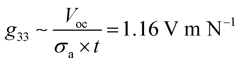 , where σa = 6 kPa is the stress magnitude and t is the thickness of the PPNG.39 Thus, PVDF–MWCNT nanofibers exhibit a superior piezoelectric figure of merit (FoM ≈ g33·d33 ≈ 5.95 × 10⁻¹¹ Pa−1) to those of the neat PVDF nanofibers (d33 ∼ 22 pC N−1 and FoM ≈ 9.7 × 10⁻¹² Pa−1) and other various state-of-the-art PVDF-based nanofibres.22 The improvement in the piezoelectric coefficient with the addition of MWCNTs is due to the high amount of the β-phase in the PVDF. We propose that the presence of MWCNTs alters the orientation of the dipoles in the PVDF nanofibers. The incorporation of fillers causes PVDF to swell leading to the formation of extended chain conformation of PVDF around the fillers. Furthermore, adding MWCNTs to reinforce PVDF fibers can enhance the crystallinity of the β-phase enhancing piezoelectric properties. The d33 value of the PVDF–MWCNT nanofibers is found to be significantly greater than those of various PVDF-based nanofibres; a comparison of nanofibres is given in Table S2 (ESI†). To explore the PPNG as an energy harvesting power source, we have demonstrated in some other way where the output voltages were measured as a function of the external load resistors (RL) (Fig. 4c) and it is obvious that the instantaneous output voltage drop across the resistive load steadily builds up as the load resistance increases and remains constant at infinitely large resistance (4 MΩ). In addition, in the same figure (Fig. 4c) the variation of the load current with the external load resistors is shown. The instantaneous output power density (P) of the PPNG was calculated as
 | (5) |
 | (6) |
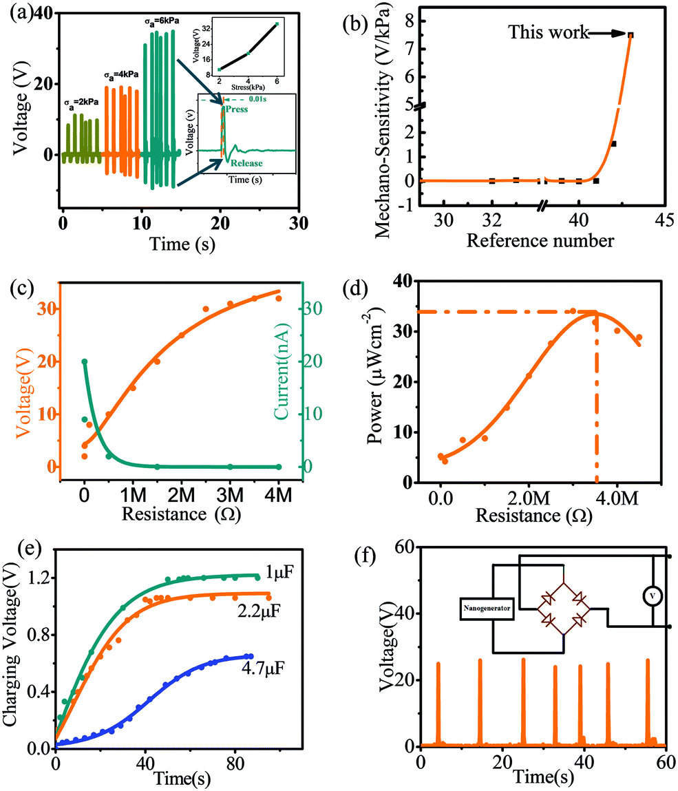 | ||
| Fig. 4 Energy harvesting characterization of nanogenerators. (a) Pressure dependent output open circuit voltage (Voc) of the PPNG, (b) mechano-sensitivity of reported piezoelectric based pressure sensors. The abscissa indicates cited references. (c) The variation of output voltage and current with external load resistances, (d) the output power as a function of external load resistances, (e) capacitor charging behavior with different capacitor values, (f) output open circuit rectified voltage response with a bridge rectifier circuit. | ||
The instantaneous piezoelectric energy conversion efficiency (ηpiezo) of the PPNG is defined as the ratio of the generated output electrical energy (by the instantaneous compressive axial stress and the residual mechanical vibration after the impacting) (Eelec) to the input mechanical energy (Emec). The optimum resistance (3.4 MΩ) was connected with the PPNG to derive optimized output performance and the output voltage per cycle was measured instantaneously, as shown in Fig. 4c and Fig. S4 (ESI†).
 | (7) |
To determine the input mechanical energy (Emec) we have to consider the total axial deformation of the PPNG under 6 kPa stress as ΔL = ε × L. Here, ε is the developed axial strain and L is the total thickness of the device. The generated axial strain is given by  where Y ∼ 0.31 GPa is the Young's modulus of the PVDF–MWCNT nanofibres.40 Thus, the total input mechanical energy per cycle is calculated as Emec = F × ΔL = 0.63 × 10⁻⁶ J, where F is the applied force.
The instantaneous piezoelectric energy conversion efficiency of the PPNG can now be written as  .
.
Finally it is found that the instantaneous piezoelectric energy conversion efficiency of the PPNG is superior to that of previously reported works.22,41 A comparison of device materials, electrode materials and percentage of piezoelectric energy conversion efficiency (%ηpiezo) of the PPNG with the reported nanogenerators is shown in Table S3 (ESI†) where in many cases the %ηpiezo of our developed device is much higher than that of previous works.
A summary or comparison of device materials, electrode materials, and output performance of the PPNG with the reported nanogenerators is shown in Table S4 (ESI†) where in many cases the output power of our developed device is much higher than that of previous works. Importantly, previous research on MWCNT reinforced PVDF composites didn’t explore the temperature and pressure dual functionality in the device form which is one of the main focus areas of this research. Table S5 (ESI†) clearly indicates the uniqueness of this work in terms of both thermal and mechanical energy harvesting over previous research.
Healthcare monitoring system
In this section the PPNG is being used as a self-powered sensor. Here the PPNG was attached on the human skin to detect slight movement of the palm, wrist, arm muscle, leg muscle, and throat (coughing and laughing situation) and different voltage responses are shown in Fig. 5a–f and the corresponding digital picture during the test is shown in the inset. The corresponding positive and negative voltages generated by palm and wrist bending and releasing are shown in Fig. 5a and b which are mainly caused by the deformation of epidermis during wrist movements. Fig. 5c and d show the output voltage response to the arm and leg muscle movement. Furthermore, the PPNG could transduce the vocal cord vibrations (Fig. 5e and f) due to the coughing and laughing situation when the device is attached to the throat. Fig. 5g and h present the Fast Fourier Transform (FFT) of the coughing and laughing signal (shown in Fig. 5e and f). The FFT treated cough acoustic frequency spectrum 200–380 Hz and laughing acoustic frequency spectrum 126–424 Hz are presented respectively which are in good agreement with the coughing and laughing sound of healthy people.22,42,43 Therefore, the PPNG can be used as a self-powered sensor to monitor and separate virus infected patients from normal humans. It is noteworthy to mention that the PPNG can be used for self-powered human-motion detection as it exhibited a good repeatability and high responsivity to strain variation caused by the joint/muscle movements without external power supply. Also this sensory information from the skin attachable/wearable PPNG is beneficial for body movement analysis during sports activities and shows its potential for use as an epidermal device for skin motion monitoring.44 | ||
| Fig. 5 PPNG for detecting human motions as a sensor. Open circuit voltages when the PPNG is attached on the human skin to detect (a) palm bending, (b) wrist motion, (c) arm muscle bending, (d) leg muscle bending, (e) coughing signal and (f) laughing signal. The insets show the corresponding photography images for the tests, (g) FFT treated cough acoustic frequency spectrum and (h) laughing acoustic frequency spectrum. | ||
Remote health monitoring
Here we have demonstrated the real time practical application of the remote health monitoring system which is very much important for continuous monitoring of both virus suspected and infected patients, and reducing the risk of caregivers being exposed to the virus. We have designed two methods using a (i) Bluetooth Module and (ii) a Nodemcu Wi-Fi Module. Fig. 6a shows the basic circuit diagram of the experimental setup for using the Bluetooth Module and Fig. 6b shows the basic circuit diagram of the experimental setup for using the IoT based remote health care monitoring system. In the first case a Bluetooth Module (HC-05), one Arduino UNO board and an Android mobile phone with the Blynk app are the main components, whereas in the second method, the main elements/components are a single chip ESP8266A Wi-Fi module and a PC/Smart phone with the Blynk app. The single chip ESP8266A has 512KB Flash memory and 10 bit ADC in set. It is run on L106, 32 bit MCU with a Real Time Operating System (RTOS). The clock speed is 80 MHz. Also it has 802.11 b/g/n and the frequency range is 2.4–2.5 G (2400–2483.5 M). With the help of MCU, we performed analog to digital conversion of the PPNG/sensor data value for processing. The waveforms are processed and the corresponding data are sent to a local server made by using the ESP8266A HTTP protocol. The patient or doctor can easily check the report on this network through WiFi/Bluetooth using their smart phones and laptops. Fig. 6c shows the real time practical circuit which shows the PPNG/sensor response under repeated finger touch in the smart phone screen through the local server for the IoT based remote health care monitoring system and Fig. 6d shows the plotted sensor output graph.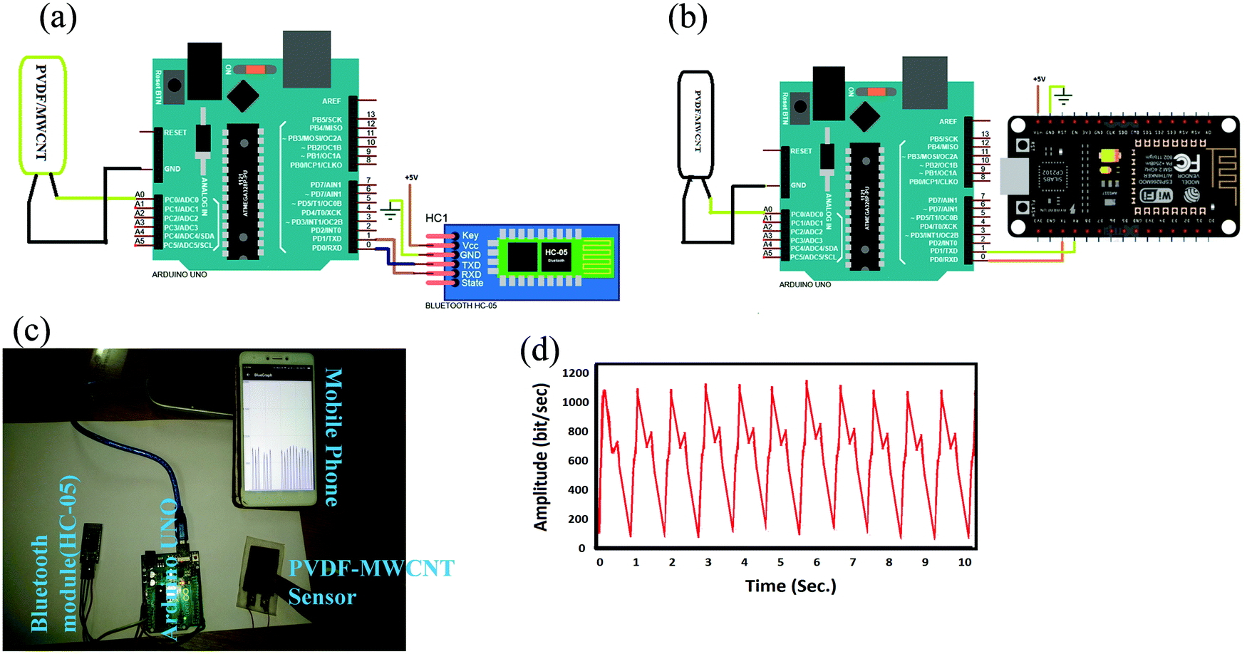 | ||
| Fig. 6 Remote health care monitoring system, (a) circuit diagram of the Bluetooth Module based experimental setup; (b) circuit diagram of the IoT based experimental setup, (c) digital image of the practical circuit with mobile showing the received sensor data wirelessly using the Blynk app and (d) sensor output response graph using finger imparting. | ||
Using this system the clinician can monitor several physiological signals such as heartbeat, respiration rate, body temperature, coughing signal and so on of the virus infected/suspected patients even in a quarantine situation round the clock wirelessly without direct physical contact with the patient which simply prevents further spread of the virus. In future, the envisioned strategy through non-invasive piezo- and pyro-electric-based wearable sensors will be grown up for infectious diseases and in vivo body implantable.45,46
3. Conclusions
In summary, we have developed a single device platform based on an all-fiber nanogenerator for harvesting both the mechanical and thermal energy using PVDF–MWCNT electrospun nanofibers as active piezo- and pyro-electric components respectively. It has been observed that the content of electroactive phases, degree of crystallinity and thermal stabilization of the β-phase within PVDF nanofibers were mainly affected by the synergistic effect of interfacial interactions and mechanical stretching forces exerted during the collection of fibers. As a consequence, the mechanically robust structure of PVDF–MWCNT nanofibers possesses an enhanced piezoelectric charge co-efficient (|d33| ∼ 51.3 pC N−1) and figure of merit (FoM ≈ 5.95 × 10⁻¹¹ Pa−1) in comparison to the neat PVDF nanofibers (|d33| ∼ 22 pC N−1 and FoM ≈ 9.7 × 10⁻¹² Pa−1). In addition to that the PPNG shows an ultra-fast response time of ∼10 ms, high electrical throughput (output voltage ∼35 V and maximum power density ∼34 μW cm−2) and power conversion efficiency (ηpiezo ∼ 19.3%). As a result, the nanogenerator drives several consumer electronic components such as commercial capacitors and LEDs by simple human finger imparting. In addition, we have also developed a human health care monitoring system where our developed sensor can distinguish different muscle vibration signals from different parts of our body. Finally, a wireless health care system for remote health monitoring using IoT and a Bluetooth module with an Arduino Uno is developed by which a clinician can monitor several physiological signals of the virus infected/suspected patients round the clock wirelessly without direct physical contact with the patient which simply prevents further spread of the virus. This type of healthcare system is urgently needed for frontline health staff during the current pandemic. Overall, the integrated device design, portable nature, and higher thermal and mechanical sensing capabilities of our developed all-fiber device could find possible applications in artificial electronic skin, prosthetic limbs, rehabilitation programs and other artificial intelligence applications in the near future to monitor dynamic tactile and strain information.4. Experimental section
Materials
We used PVDF pellets (Mw = 275![[thin space (1/6-em)]](https://www.rsc.org/images/entities/char_2009.gif) 000, Sigma-Aldrich, USA), acetone (Merck Chemical, India), N,N-dimethyl formamide (DMF from Merck) and MWCNT powder (Merck, India).
000, Sigma-Aldrich, USA), acetone (Merck Chemical, India), N,N-dimethyl formamide (DMF from Merck) and MWCNT powder (Merck, India).
The remote healthcare system included an Arduino Uno which is an ATMega 328 microcontroller based system, an Arduino Uno based Wi-Fi Shield ESP8266MOD which is used as an IoT based gateway for establishment of communication with the IoT cloud and the system and a Bluetooth module (HC-05) and our proposed nanofiber based sensor.
Fabrication of electrospun nanofibers
The PVDF solution was prepared by dissolving 12 wt% of PVDF pellets in DMF/acetone (60:40 v/v) solution under continuous stirring until the solution was acquired. Then 0.2 wt% (w/v%) of MWCNTs was added to the resulting solution. The solution was stirred, followed by sonication in an ultra-sonication bath at room temperature until uniformly dispersed MWCNTs within the PVDF solution were obtained. Then, the resulting solution was placed in a plastic syringe (15 mL) tipped with a stainless steel needle with an inner diameter of 0.5 mm. Electrospinning was carried out at 11 kV from a high voltage power supply, where the stainless steel needle is connected to the positive terminal of the high voltage power supply and the metallic collector is grounded. A syringe pump was applied to deliver the solution into the needle tip at a flow rate of 0.5 ml h−1 and the electrospun nanofibers were collected through the aluminum-foil covered roller collector. The needle-to-roller collector distance of 12 cm was optimized. All experiments were supervised at room temperature and a relative humidity of 43 ± 5%. The schematic of the electrospinning set up used for the fabrication of the large area PVDF–MWCNT nanofiber mat is shown in Fig. S5 (ESI†).
Fabrication of the all-fiber PPNG
The details of the fabrication process of our proposed all-fiber PPNG are discussed in the section “All-Fiber nanogenerator/sensor fabrication strategy”, under the Results and discussion part. The details of the device structure are shown in Fig. 1. Here the copper (Cu)–nickel (Ni) plated interlocked micro-fiber based polyester fabric (supplied by Coatex Industries, India) was used as the top and bottom electrodes and the PVDF–MWCNT nanofibers were used as the active layer. Finally the PPNG was further encapsulated with PDMS (Sylgard 184 silicone elastomer) for protection from the environment and to ensure a compact structure of the device. The complete thickness (t) of the PPNG is ∼5 mm and the effective contact area of the PPNG is 7.5 cm2.5. Characterization
To investigate in detail the surface morphology of the electrospun fibers, field emission scanning electron microscopy (FE-SEM, FEI, INSPECT F50) was undertaken at an acceleration voltage of 20 kV. The structural composition of the electrospun fibers was measured by Fourier transform infrared spectroscopy (FT-IR) (Bruker, Tensor II). X-ray diffraction (XRD) patterns of the electrospun nanofibers were recorded using an X-ray diffractometer (Bruker D8 Advance) with CuKα (λ ∼ 1.5406 Å) monochromatic radiation operated at 40 kV and 30 mA. Finally the output voltage response from the PPNG under different applied stress was recorded using a digital oscilloscope (Agilent DSO3102A) and current measurements were carried out using a Keithley 6485 picoammeter.Conflicts of interest
The authors declare no competing financial interest.Acknowledgements
This work was financially supported by a grant from the Science and Engineering Research Board (EEQ/2018/001130), Government of India. Kuntal Maity and Krittish Roy are thankful to the UGC (No. P-1/RS/319/14) and DST (IF160559) for providing the fellowship. Finally, we are grateful to Prof. Christopher Rhys Bowen for reading the entire manuscript and for providing valuable comments and corrections.References
- A. Kaur and A. Jasuja, Adv. Comput. Sci. Inf. Technol., 2017, 4, 80–84 Search PubMed.
- S. K. Ghosh, K. Roy, H. K. Mishra, M. R. Sahoo, B. Mahanty, P. N. Vishwakarma and D. Mandal, ACS Sustainable Chem. Eng., 2020, 8, 864–873 Search PubMed.
- H. He, T. Zhao, H. Guan, T. Zhong, H. Zeng, L. Xing, Y. Zhang and X. Xue, Sci. Bull., 2019, 64, 1409–1417 Search PubMed.
- H. Guan, T. Zhong, H. He, T. Zhao, L. Xing, Y. Zhang and X. Xue, Nano Energy, 2019, 59, 754–761 Search PubMed.
- Y. Zang, F. Zhang, C. Di and D. Zhu, Mater. Horiz., 2015, 2, 140–156 Search PubMed.
- Z. Liu, T. Zhao, H. Guan, T. Zhong, H. He, L. Xing and X. Xue, J. Mater. Sci. Technol., 2019, 35, 2187–2193 Search PubMed.
- S. H. Lee, C. K. Jeong, G.-T. Hwang and K. J. Lee, Nano Energy, 2015, 14, 111–125 Search PubMed.
- R. G. Multhaupt, Ferroelectrics, 1987, 75, 385–396 Search PubMed.
- B. Mahanty, S. K. Ghosh, S. Garain and D. Mandal, Mater. Chem. Phys., 2017, 186, 327–332 Search PubMed.
- S. K. Ghosh, W. Rahman, T. R. Middya, S. Sen and D. Mandal, Nanotechnology, 2016, 27, 215401 Search PubMed.
- D. R. Dillon, K. K. Tenneti, C. Y. Li, F. Ko, I. Sics and B. S. Hsiao, Polymer, 2006, 47, 1678–1688 Search PubMed.
- K. Maity, B. Mahanty, T. K. Sinha, S. Garain, A. Biswas, S. K. Ghosh, S. Manna, S. K. Ray and D. Mandal, Energy Technol., 2017, 5, 234–243 Search PubMed.
- K. Park, S. Xu, Y. Liu, G.-T. Hwang, S.-J. L. Kang, Z. L. Wang and K. J. Lee, Nano Lett., 2010, 10, 4939–4943 Search PubMed.
- Y. M. Yousry, K. Yao, S. Chen, W. H. Liew and S. Ramakrishna, Adv. Electron. Mater., 2018, 4, 1700562 Search PubMed.
- D. Mandal, S. Yoon and K. J. Kim, Macromol. Rapid Commun., 2011, 32, 831–837 Search PubMed.
- L. Wang, Y. Wang, M. Wu, Z. Wei, C. Cui, M. Mao, J. Zhang, X. Han, Q. Liu and J. Ma, Small, 2018, 14, 1800737 Search PubMed.
- P. Martins, A. C. Lopes and S. L. Mendez, Prog. Polym. Sci., 2014, 39, 683–706 Search PubMed.
- B. Mahanty, S. K. Ghosh, S. Jana, K. Roy, S. Sarkar and D. Mandal, Sustainable Energy Fuels, 2021, 5, 1003–1013 Search PubMed.
- A. Biswas, K. Henkel, D. Schmeißer and D. Mandal, Phase Transitions, 2017, 19, 1205 Search PubMed.
- D. Chen, M. Wu, W. Wang and T. Liu, J. Macromol. Sci., Part B: Phys., 2010, 49, 1069–1082 Search PubMed.
- S. K. Ghosh, M. Xie, C. R. Bowen, P. R. Davies, D. J. Morgan and D. Mandal, Sci. Rep., 2017, 7, 16703 Search PubMed.
- S. K. Ghosh and D. Mandal, Nano Energy, 2018, 53, 245–257 Search PubMed.
- G. H. Kim, S. M. Hong and Y. Seo, Phys. Chem. Chem. Phys., 2009, 11, 10506–10512 Search PubMed.
- K. Roy, S. K. Ghosh, A. Sultana, S. Garain, M. Xie, C. R. Bowen, K. Henkel, D. Schmeiβer and D. Mandal, ACS Appl. Nano Mater., 2019, 2, 2013–2025 Search PubMed.
- C. R. Bowen, H. A. Kim, P. M. Weaver and S. Dunnc, Energy Environ. Sci., 2014, 7, 25–44 Search PubMed.
- S. K. Ghosh, T. K. Sinha, M. Xie, C. R. Bowen, S. Garain, B. Mahanty, K. Roy, K. Henkel, D. Schmeißer, J. K. Kim and D. Mandal, ACS Appl. Electron. Mater., 2021, 3, 248–259 Search PubMed.
- Y. Yang, K. C. Pradel, Q. Jing, J. M. Wu, F. Zhang, Y. Zhou, Y. Zhang and Z. L. Wang, ACS Nano, 2012, 6, 6984–6989 Search PubMed.
- T. Zhao, W. Jiang, H. Liu, D. Niu, X. Li, W. Liu, X. Li, B. Chen, Y. Shi, L. Yin and B. Lu, Nanoscale, 2016, 8, 8111–8117 Search PubMed.
- C. Li, P.-M. Wu, S. Lee, A. Gorton, M. J. Schulz and C. H. Ahn, J. Microelectromech. Syst., 2008, 17, 334–341 Search PubMed.
- B. Wang, C. Liu, Y. Xiao, J. Zhong, W. Li, Y. Cheng, B. Hu, L. Huang and J. Zhou, Nano Energy, 2017, 32, 42–49 Search PubMed.
- A. Wang, M. Hu, L. Zhou and X. Qiang, Nanomaterials, 2018, 8, 1021–1032 Search PubMed.
- G. Zhao, X. Zhang, X. Cui, S. Wang, Z. Liu, L. Deng, A. Qi, X. Qiao, L. Li, C. Pan, Y. Zhang and L. Li, ACS Appl. Mater. Interfaces, 2018, 10, 15855–15863 Search PubMed.
- Y. R. Wang, J. M. Zheng, G. Y. Ren, P. H. Zhang and C. Xu, Smart Mater. Struct., 2011, 20, 045009 Search PubMed.
- W. Guo, C. Tan, K. Shi, J. Li, X. X. Wang, B. Sun, X. Huang, Y.-Z. Long and P. Jiang, Nanoscale, 2018, 10, 17751–17760 Search PubMed.
- T. Sharma, S.-S. Je, B. Gill and J. X. J. Zhang, Sens. Actuators, A, 2012, 177, 87–92 Search PubMed.
- S. M. Hosseini and A. A. Yousefi., Org. Electron., 2017, 50, 121–129 Search PubMed.
- Q.-L. Zhao, G.-P. He, J.-J. Di, W.-L. Song, Z.-L. Hou, P.-P. Tan, D.-W. Wang and M.-S. Cao, ACS Appl. Mater. Interfaces, 2017, 9, 24696–24703 Search PubMed.
- M. Sharma, V. Srinivas, G. Madras and S. Bose, RSC Adv., 2016, 6, 6251 Search PubMed.
- S. K. Ghosh and D. Mandal, ACS Sustainable Chem. Eng., 2017, 5, 8836–8843 Search PubMed.
- Z. H. Liu, C. T. Pan, L. W. Lin and H. W. Lai, Sens. Actuators, A, 2013, 193, 13–24 Search PubMed.
- S. K. Ghosh and D. Mandal, Nano Energy, 2016, 28, 356–365 Search PubMed.
- P. Piirila and A. R. A. Sovijarvi, Eur. Respir. J., 1995, 8, 1949–1956 Search PubMed.
- J.-A. Bachorowski, M. J. Smoski and M. J. Owren, J. Acoust. Soc. Am., 2001, 110, 1581–1597 Search PubMed.
- T. Ray, J. Choi, J. Reeder, S. P. Lee, A. J. Aranyosi, R. Ghaffari and J. A. Rogers, Curr. Opin. Biomed. Eng., 2019, 9, 47–56 Search PubMed.
- S. K. Ghosh and D. Mandal, J. Mater. Chem. A, 2021, 9, 1887–1909 Search PubMed.
- S. K. Ghosh, J. Park, S. Na, M. P. Kim and H. Ko, Adv. Sci., 2021, 2005010, DOI:10.1002/advs.202005010.
Footnotes |
| † Electronic supplementary information (ESI) available: The digital image of fabricated PPNG, piezoelectric response for neat PVDF based nanogenerators, the schematic of electrospinning set up used for fabrication of large area PVDF–MWCNT nanofiber mat. See DOI: 10.1039/d1ma00131k |
| ‡ Present address: NEST, Istituto Nanoscienze-CNR, Piazza S. Silvestro 12, I-56127 Pisa, Italy. |
| This journal is © The Royal Society of Chemistry 2021 |