
 Open Access Article
 This Open Access Article is licensed under a Creative Commons Attribution-Non Commercial 3.0 Unported Licence
Boosting methane partial oxidation on ceria through exsolution of robust Ru nanoparticles†
A. J.
Carrillo
 ,
L.
Navarrete
,
M.
Laqdiem
,
M.
Balaguer
and
J. M.
Serra
*
,
L.
Navarrete
,
M.
Laqdiem
,
M.
Balaguer
and
J. M.
Serra
*
Instituto de Tecnología Química, Universitat Politècnica de València-Consejo Superior de Investigaciones Científicias, Avenida Los Naranjos s/n, 46022 Valencia, Spain. E-mail: jmserra@itq.upv.es
First published on 2nd March 2021
Abstract
Finding sustainable routes for the transformation of CO2 into fuels and added-value chemicals is key for mitigating greenhouse gas emission. In this respect, chemical-looping reforming coupled with CO2 splitting emerges as a promising technology to produce syngas, using waste or solar heat as an energy source. It relies on metal oxides that act as redox intermediates and, thus, the stability and catalytic activity of the oxides are crucial. For that purpose, ceria has been widely used due to its superior multicyclic stability and fast CO2 splitting kinetics. However, it also presents low capacity for oxygen exchange or supply compared with other oxides and slow methane partial oxidation kinetics, which is normally improved by cationic doping or catalytic surface activation via metal impregnation. The high temperatures (900 °C) required for these reactions lead to catalyst deactivation over time due to sintering of metallic clusters. In order to circumvent this issue, in this work we have utilized the exsolution method to create uniformly dispersed Ru nanoparticles (ca. 5 nm) that remain anchored to the cerium oxide backbone, guaranteeing its microstructural stability and catalytic activity over prolonged cycling. We provide evidence for metallic Ru exsolution and further demonstrate the outstanding benefits of exsolved nanoparticles in the partial oxidation of methane following a chemical-loop reforming scheme, especially in the temperature range in which industrial waste heat could be used as an energy source to drive the reaction. Remarkably, at 700 °C surface functionalization with exsolved Ru nanoparticles enables high CO selectivity (99% versus 62% for CeO2) and about 2 orders of magnitude faster H2 production rates. The dispersion and size of the exsolved Ru nanoparticles were maintained after a durability test of 20 chemical loops at 900 °C, indicating their robustness. Overall, the results presented here point towards the unique characteristics of nanoparticle exsolution for preventing agglomeration, which could find application in other catalytic or electrochemical processes for target hydrocarbon production.
1. Introduction
The intensification of chemical processes through the implementation of membrane reactors or chemical-looping schemes1 is an attractive alternative for the sustainable production of fuels with reduced CO2 footprint and increased exergy efficiency.2,3 In particular, chemical-looping reforming of methane (e.g. natural gas or biogas) coupled with CO2 splitting represents a unique niche for production of fuels utilizing two greenhouse gases as reagents.4 In the first step, CH4 is partially oxidized with the lattice oxygen of a metal oxide, CeO2 in this case (eqn (1); Fig. 1). This reaction results in the production of H2 and CO, known as syngas, in a 2![[thin space (1/6-em)]](https://www.rsc.org/images/entities/char_2009.gif) :1 molar ratio, which is ideal for further processing into liquid fuels via the Fischer–Tropsch process. In the second step, the reduced metal oxide is reoxidized with CO2, producing CO (eqn (2)). Importantly, the first step, which is an endothermic reaction occurring at high temperatures (800–1000 °C), could be driven with waste5 or concentrated solar heat6–8
:1 molar ratio, which is ideal for further processing into liquid fuels via the Fischer–Tropsch process. In the second step, the reduced metal oxide is reoxidized with CO2, producing CO (eqn (2)). Importantly, the first step, which is an endothermic reaction occurring at high temperatures (800–1000 °C), could be driven with waste5 or concentrated solar heat6–8 | (1) |
 | (2) |
 | (3) |
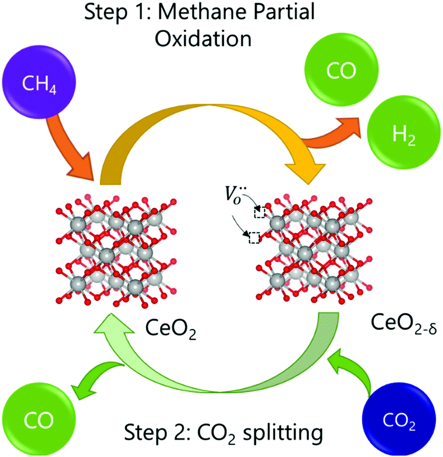 | ||
| Fig. 1 Schematic of the chemical looping reforming of methane process studied in this work. In the first step, CH4 reacts with the lattice oxygen from CeO2, resulting in the formation of CO and H2. In the second step, CO2 reacts with the reduced oxide (CeO2−δ), replenishing the oxygen vacancies formed in the first step, and, subsequently, forming CO. | ||
This 2-step cyclic process presents several operational advantages. First, the main side reaction in thermocatalytic dry reforming, reverse water gas shift, is avoided. Secondly, carbon depositions caused by methane cracking in the first step could be transformed into CO during the second step by the Boudouard reaction.9 To guarantee the feasibility of the process, it is key to find stable redox materials that could withstand repeated high-temperature thermochemical cycling. In this respect, ceria has been widely studied due to its high structural stability at high temperatures and fast CO2 splitting kinetics,6,10 based on its performance tested in solar-driven reactors.9,11–13 However, the limited oxygen-exchange capacity of ceria could hamper its further applicability. In order to overcome this problem, doping with other cations, such as Zr14 or La,5 has been employed in order to increase the reducibility of cerium oxides and, subsequently, the fuel yields obtained by H2O and/or CO2 splitting. Morphological modifications15 or combinations in the form of composites with other metal oxides such as perovksites16 or binary oxides17,18 have been also successfully tested. Additionally, during the methane partial oxidation (MPO) step, most literature reports show syngas selectivity far from 100%,6 which results from the combustion of CH4 with readily available oxygen anions at the CeO2 surface producing CO2 and H2O. In order to solve this problem, surface promotion with metallic nanoparticles is commonly used in chemical looping reforming.2 In the case of CeO2, noble metals such as Pt or Rh19 or Ni in Ti-doped CeO220 have been employed to suppress the formation of oxygenated molecules and increase H2 and CO selectivity. In the latter case, Ni decorated Ti-doped CeO2 resulted in CO selectivity (SCO) values of ca. 80%.20 These metallic catalysts are commonly incorporated in the oxide surface via impregnation methods; however, at the high temperatures needed to drive the reduction of the metal oxide with methane, metal nanoparticles can suffer sintering with neighboring particles, which affects its catalytic activity during prolonged operation.21 In this sense, the exsolution method emerges as a promising alternative to obtain more durable metal nanoparticles with high catalytic activity. Nanoparticle exsolution consists of migration, under reductive atmospheres, of metal cations contained in the oxide lattice to the oxide surface, forming nanoparticles that remain anchored to the oxide backbone.22 The fact that the nanoparticles are socketed into the oxide surface imparts beneficial effects in terms of stability, avoiding nanoparticle sintering.23 For this reason, exsolution has gained considerable attention in the field of solid oxide fuel cells and electrolyzers,24,25 and more recently its application has been found to be promising in methane reforming reactions.26–29 For instance, Kousi and co-workers obtained exsolved and submerged Ni nanoparticles on La0.8Ce0.1Ni0.4Ti0.6O3 which synergistically enhanced the oxygen supply capacity.26 Additionally, Co incorporation into the B-site enables the activation of methane at temperatures as low as 450 °C.30 For simultaneous methane partial oxidation coupled with CO2 splitting, Dimitrakopoulos et al. used a membrane reactor in which the exsolved nanoparticles were formed in situ during the reaction.31 More recently, Carrillo et al. demonstrated the beneficial effects of Co exsolution in the La0.6Sr0.4Cr0.8Co0.2O3 perovskite for syngas production, leading to faster MPO and CO2 splitting rates, higher syngas selectivity and stable nanoparticle size over 28 chemical loops.32 Regarding ceria and other fluorite type structures, the exsolution method has been scarcely explored. Recently, Naeem et al. demonstrated that Ru exsolution could boost the catalytic stability of Sm2RuxCe2−xO7 materials for methane dry reforming, especially when compared with Sm–Ce pyrochlores with impregnated Ru particles, denoting the beneficial effects of nanoparticle anchoring via exsolution.27 Based on these recent discoveries, in this work, we have applied the exsolution method to create robust Ru nanoparticles that could boost syngas production via chemical looping reforming of methane coupled with CO2 splitting, which to date has not been tested for ceria-based materials. The results reported herein denote the benefits of nanoparticle exsolution and could open the path for designing more stable cerium catalysts for other thermocatalytic applications or solid oxide electrochemical reactors and electrolyzers.33–36
2. Results and discussion
2.1. Physicochemical insights into Ru nanoparticle exsolution on CeO2
Ruthenium doped cerium oxide, Ru0.01Ce0.99O2 (Ru–CeO2), was prepared via a modified version of the Pechini method (see the Experimental section). For benchmarking, CeO2 was also synthesized following the same method. According to the X-ray diffractograms depicted in Fig. 1, pristine Ru–CeO2 and CeO2 presented solely the reflections of fluorite CeO2, space group Fm3m. Interestingly, incorporation of Ru into the fluorite crystal induced a lattice expansion according to the shift of the main reflection to lower 2θ values, pointing to the presence of a solid solution. The cubic lattice parameter, a, was calculated for both materials and was found to be 5.405 and 5.421 Å for CeO2 and Ru–CeO2, respectively. This result is somehow counterintuitive since the ionic radius for Ce4+ in 8-fold coordination is 0.97 Å, whereas for Ru4+ (in 6-fold coordination) it is 0.64 Å,37 which would suggest lattice shrinkage. However, this result is in accordance with previous works that reported a lattice expansion with Ru doping.38,39 In order to confirm the lattice expansion upon Ru substitution we analyzed the materials with Raman spectroscopy (Fig. 2b). Due to the high symmetry of the cubic fluorite structure, CeO2 has a unique Raman band ascribed to a one triply degenerate oxygen breathing mode of F2g symmetry.40 This mode normally occurs at 465 cm−1; however, under the instrumental conditions used here, a red laser of 785 cm−1 wavelength, the F2g peak for undoped CeO2 is at 463.7 cm−1. Upon Ru incorporation, the mode slightly shifted towards lower wavenumbers, 463.3 cm−1, which corroborates the lattice expansion observed by XRD. Interestingly, no bands associated with oxygen vacancies, the region between 550 and 600 cm−1,27 were observed for Ru–CeO2.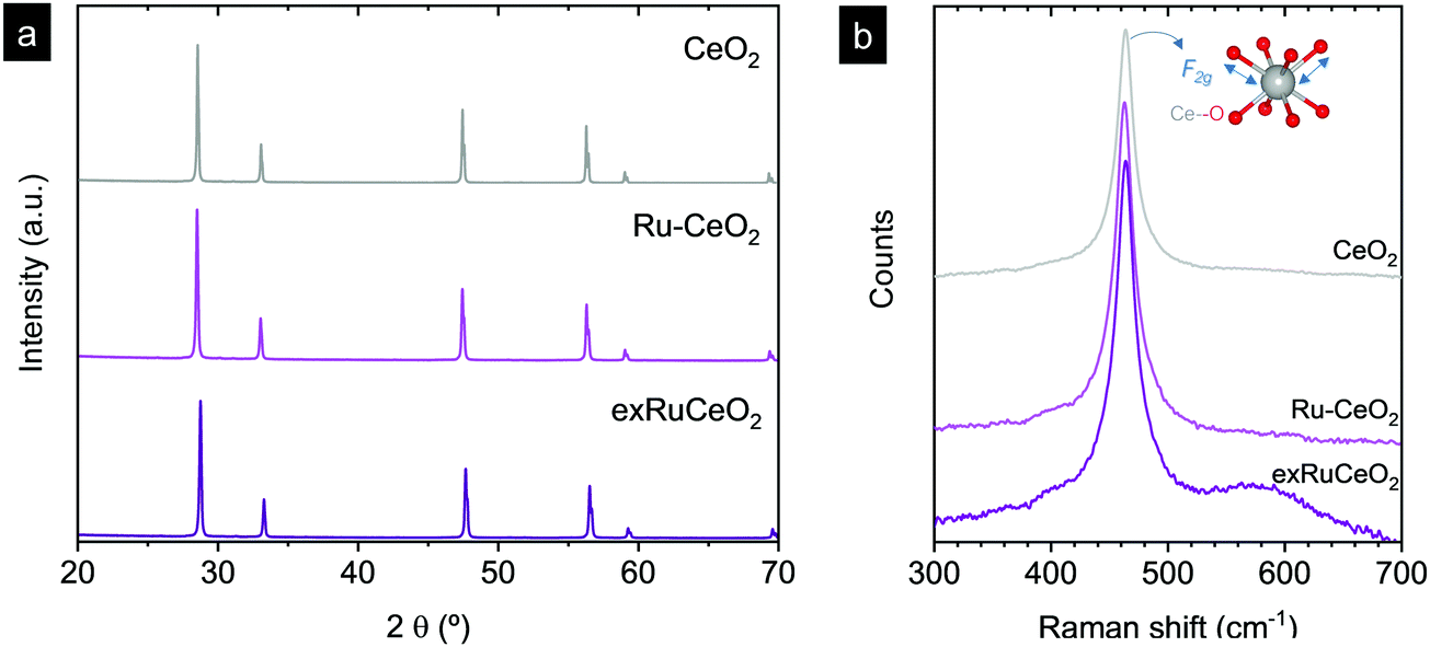 | ||
| Fig. 2 X-ray diffraction patterns (a) and Raman spectra (b) for Ru–CeO2 before and after exsolution performed at 900 °C for 2 h under 5% H2 flow (exRuCeO2) and for CeO2. Raman spectra were collected with a 785 cm−1 laser. The inner sketch in (b) depicts the vibration of oxygen anions around the Ce cation associated with the F2g Raman mode. | ||
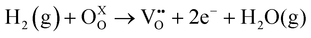
Fig. 2a also shows the XRD diffraction patterns for Ru–CeO2 material after the exsolution process performed at 900 °C for 2 h under a 5% H2 atmosphere, revealing that the fluorite crystal phase prevailed after the reductive treatment without the appearance of any secondary phase. However, when scrutinizing the materials’ morphology before and after exsolution, important differences were observed. Fig. 3 depicts the SEM images of Ru–CeO2 before and after the exsolution treatment. Fig. 3a reveals that Ru–CeO2 is formed by aggregates of necked micron-sized particles. Fig. S1 (ESI†) shows the EDX elemental analysis of the pristine material. However, after 2 h reduction in 5% H2, well-dispersed nanoparticles emerged over the oxide surface indicative of nanoparticle exsolution (Fig. 3b). Turning back to the XRD diffraction, the exsolution treated Ru–CeO2 sample (exRuCeO2) experienced a shift towards higher 2θ values, denoting lattice shrinkage. That is to say, exRuCeO2 presented a cubic lattice parameter, a, of 5.413 Å, whereas for the pristine sample it was 5.421 Å. This slight lattice contraction was also observed in the Raman spectra depicted in Fig. 2b. The F2g peak position for exRuCeO2 is at 464.5 cm−1, which is one wavenumber higher compared to that for Ru–CeO2. In addition, exRuCeO2 exhibited the Raman modes ascribed to oxygen vacancies at around 550–600 cm−1.41 This indicates that the exsolution treatment in the reductive atmosphere triggers the creation of oxygen vacancies in addition to the exsolved nanoparticles. Although both XRD and Raman analyses point toward lattice contraction upon nanoparticle exsolution, the origin of this phenomenon is not clear. Previous reports on reduction of Ru–CeO2 at 500 °C in a H2 atmosphere showed a slight lattice expansion upon reduction;38 however, in that work the presence of exsolved Ru nanoparticles was not inferred. Under the present reductive atmosphere, the lattice oxygen reacts with H2 giving rise to electrons and oxygen vacancies, as demonstrated by Raman (Fig. 2b), which in the Kroger–Vink notation can be written as
 | (4) |
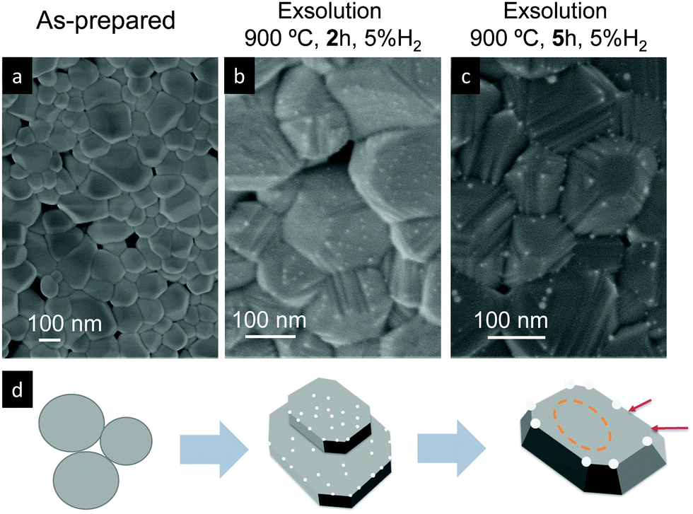 | ||
| Fig. 3 SEM images of Ru-doped CeO2 samples: (a) pristine and after exsolution treatment for (b) 2 h and (c) 5 h at 900 °C under a 5% H2 atmosphere. (d) Schematic depicting the morphology transformations at each stage. | ||
Subsequently, the oxidation state of cerium cations will be lowered according to Ce4+ + e− →Ce3+.42 Commonly, it has been believed that lattice expansion of CeO2 upon reduction has been ascribed to the larger ionic radii of Ce3+ (1.143 Å) compared to that of Ce4+ (0.97 Å) cations. However, Muhich demonstrated that Ce3+–O2− elongation can be compensated by Ce4+–O contraction, with the lattice expansion being driven by non-counterpoised forces.43 Anyhow, the nucleation of exsolved metallic nanoparticles compensates to a certain extent the expansion with contraction,42 which for this particular case, Ru4+ + 4e− →Ru0, could be higher explaining the slight lattice contraction upon metallic exsolution. In order to shed more light on this matter, we analyzed these three materials with Temperature Programmed Reduction (TPR). The TPR results (Fig. S2, ESI†) showed a common peak at ca. 800 °C peak maximum, ascribed to the reduction of the Ce4+ bulk species.44 Interestingly, for both CeO2 and RuCeO2 this peak is located at 800 °C. Normally, partial substitution of Ce4+ in doped ceria materials leads to a shift of this peak toward lower temperatures due to the creation of oxygen vacancies that facilitate oxygen diffusion.45,46 However, in this case Ru-doping did not result in the same effect, which might corroborate that Ru cations are located in interstitial positions, rather than partially substituting the Ce4+ cations, which results in the lattice expansion. After the exsolution treatment (5% H2, 900 °C, 2 h) of the exRuCeO2 material, the main peak shifted to 769 °C. This shift to lower temperatures is ascribed to the presence of oxygen vacancies, as corroborated by Raman spectra. This fact is in principle beneficial for the MPO step, indicating that exRuCeO2 could outperform CeO2 at lower temperatures. Additionally, with the TPR analyses it was possible to determine the oxygen exchange/supply capacity of the materials (see the Experimental section for more details). Our results indicate that the oxygen supply capacity of exRuCeO2 was equal to 0.18 mol O moloxide−1, whereas for CeO2 it was 0.09 mol O moloxide−1. Despite the increased value for exRuCeO2 with respect to CeO2, the oxygen supply capacity is still below the values reported for perovskites, for instance ca. 0.4 mol O moloxide−1 for La0.8Ce0.1Ni0.4Ti0.6O3−δ.30
SEM analysis (Fig. 3b) of the sample reduced for 2 h in H2 at 900 °C reveals the formation of exsolved nanoparticles (d ∼ 2–5 nm), well dispersed over all the facets of the oxide. Interestingly, when increasing the exsolution treatment up to 5 h (Fig. 3c) the nanoparticle size increases, as previously observed in Ni exsolution in perovskites,47,48 and grow mainly in the edges of the oxide particles, which progressively change from a rounded-like shape into a more faceted morphology caused by a longer exposure to the reductive environment. The changes in the exsolved nanoparticle habitus depending on time are reflected in the schematic depicted in Fig. 3d.
We now turn to TEM to further analyze the size and level of anchorage of the exsolved Ru nanoparticles. Fig. 4a depicts some grains of exRuCeO2 and the presence of exsolved nanoparticles over the oxide backbone. At higher magnifications (Fig. 4b), it is possible to observe that the nanoparticle is embedded in the oxide backbone, confirming the level of anchorage characteristic from metal nanoparticle exsolution.49Fig. 4c shows the HAADF-STEM image of exRuCeO2, in which it is possible to observe the high and uniform dispersion of exsolved nanoparticles over the oxide backbone. EDX was utilized to further explore the nature of the exsolved nanoparticles (Fig. 4d), by analyzing two different zones in Fig. 4c, one pointing to an exsolved particle (point 1) and the other pointing to the oxide surface (point 2). By comparison, one can observe the higher concentration of Ru on the exsolved nanoparticles. Although Ru exsolution on Sm2Ce2O7 pyrochlores has been recently reported,27 to the best of our knowledge this work represents the first demonstration of Ru exsolution from the CeO2 fluorite host.
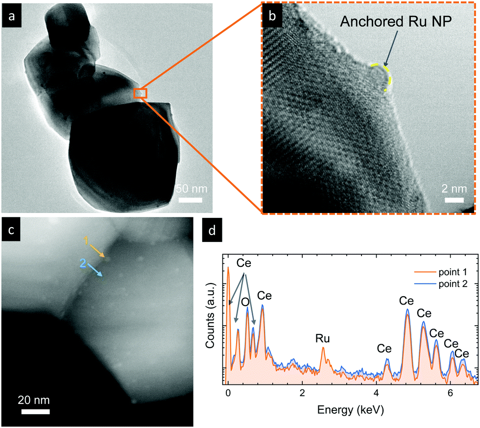 | ||
| Fig. 4 (a and b) TEM images of Ru-doped CeO2 after exsolution treatment for (b) 2 h at 900 °C in a 5% H2 atmosphere. (c) HAADF-STEM image for the same material and (d) EDX point analysis of an exsolved nanoparticle (point 1) and the bare oxide surface (point 2). | ||
To further explore the nature of the exsolved nanoparticles we performed X-ray photoemission spectroscopy (XPS; Fig. 5). In order to analyze the oxidation state of Ru, we checked the Ru3p core shell, since Ru5d overlaps with C1s.34,38,39Fig. 5a compares the Ru3p spectra for Ru–CeO2 before and after exsolution (i.e., for exRuCeO2). The Ru3p3/250 binding energy for Ru–CeO2 was observed at 463.26 eV, whereas after exsolution, it shifted to 461.64 eV, indicative of the Ru metal.34,38,39 This shift indicates that for the Ru–CeO2 sample Ru is in the 4+ oxidation state, and after the 2 h reduction in 5% H2 at 900 °C, all the Ru at the surface is in the metal state, corroborating that the exsolved nanoparticles observed by SEM (Fig. 3) and TEM (Fig. 4) are solely composed of the Ru metal. XPS analysis of Ce3d core-level spectra are depicted in Fig. 5b. The 3d5/2 and 3d3/2 components correspond to v and u, respectively, whereas v′′, v′′′ and u′′, u′′′ are the satellites, respectively. Additionally, the doublets v0, u0 and v′, u′ correspond to Ce3+.51–53 A detailed description of the deconvolution of each of these components can be found in the ESI† (Tables S1–S3,). According to the spectra depicted in Fig. 5b, it can be inferred that there is little presence of Ce3+ in the surface of Ru–CeO2, which slightly increases after exsolution, as revealed for exRuCeO2. The O1s spectra depicted in Fig. 5c indicate that for the three materials the major component is located at binding energies around 529 eV, which is generally ascribed to the lattice oxygen in oxides.51 In addition, for Ru–CeO2 and exRuCeO2 there is a feature around 531 eV representative of oxygen anions in the vicinity of oxygen vacancies, indicating the presence of oxygen vacancy sites in the surface of these materials. For the case of CeO2, the components around 533 and 534 eV could be ascribed to adsorbed species.
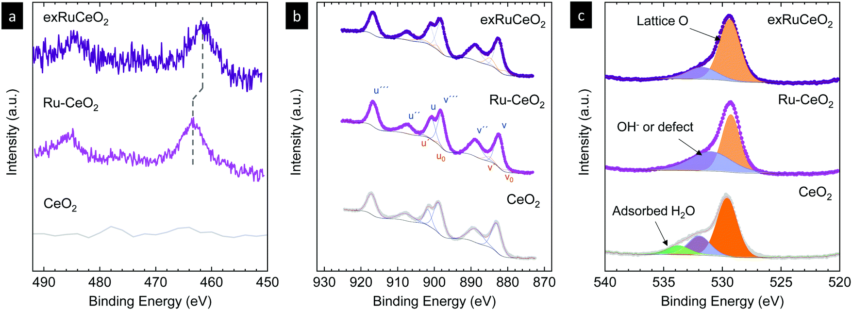 | ||
| Fig. 5 X-ray photoemission spectra of (a) Ru3p, (b) Ce3d and (c) O1s core levels of CeO2 and Ru-doped CeO2 before (Ru–CeO2) and after exsolution of Ru nanoparticles (exRuCeO2). | ||
In this section, we have presented the thorough physicochemical characterization of the materials before and after exsolution, confirming the presence of anchored metallic Ru nanoparticles over cerium-based oxides. In the following, the performance of exRuCeO2 for chemical looping methane reforming coupled with CO2 splitting will be interrogated, paying special attention to the reaction rate improvement and nanoparticle stability after prolonged cycling.
2.2. Improving methane partial oxidation with Ru exsolution
Chemical looping methane reforming coupled with CO2 splitting reactions was performed in a fixed-bed tubular quartz reactor and the gas production was monitored via mass spectrometry. First, we focus on determining the impact of Ru nanoparticles on syngas production, and for that, we benchmark exRuCeO2 against CeO2. As commented in the introduction, one of the main drawbacks of CeO2 for chemical looping reforming is that it presents slow syngas production during the partial oxidation of methane, which is the first step of this redox cyclic process (Fig. 1). In this first set of experiments, chemical looping reforming coupled with CO2 splitting was assessed at three different temperatures (900, 800, 700 °C) for both materials, i.e., exRuCeO2 and CeO2. Here, it should be noted that the exsolution process was carried out inside the reactor, prior to the chemical looping reforming tests. We first assessed the influence of temperature on the chemical looping reforming performance of CeO2. Fig. 6a depicts the reactions occurring at 900 °C, which start with the injection of a stream of 5 vol% of CH4, resulting in the formation of H2 and CO, which are the products of the partial oxidation of methane, and CO2, which results from the complete oxidation of CH4 with the lattice oxygen. For further information, Fig. S3 (ESI†) also shows the CH4 curve in order to show the methane consumption, as well as the O2 production curve, which clearly illustrates the absence of this gas during the experiments. The formation of CO2 occurred at the beginning of the reaction, which is indicative of CH4 reaction with readily available oxygen species at the surface of the ceria.54 The CO2 production in the first stage of the reaction lasted for ca. 1 min. Simultaneously, the formation of H2 and CO occurred steadily until CH4 injection was suppressed. At 900 °C, CO selectivity, SCO, was equal to 80% because of the prominent formation of CO2; see Fig. 7 for the selectivity data at the different temperatures tested. The peak gas production rate was 2.9 and 1.3 mL min−1 g−1 for H2 and CO, respectively, resulting in a H2:CO ratio slightly higher than the stoichiometric 2:1 proportion, indicative of CH4 decomposition into solid C and additional H2 formation. Once CH4 injection was complete, Ar was flushed to purge the reactor for 2 min, followed by the injection of CO2 (5 vol%). As mentioned in the introduction (Fig. 1), the methane partial oxidation step generates oxygen vacancies in the cerium oxide, since the lattice oxygen reacts with CH4. Thus, in the oxidation step, CO2 reacts with the reduced cerium oxide (CeO2−δ), replenishing most of the oxygen vacancies with oxide anions, and subsequently forming CO, as observed in the second step in Fig. 6a. Once CO2 is injected inside the reactor, a fast CO production is observed (peak production rate of 18.2 mL min−1 g−1), that lasted for 2 min until CO2 splitting reaction reached equilibrium. This fact indicates that this CeO2−δ-reoxidation step could be performed with shorter CO2 injections, which will eventually increase the CO2 conversion per cycle, denoting the high extent of operational tunability and room for optimization of this technology.
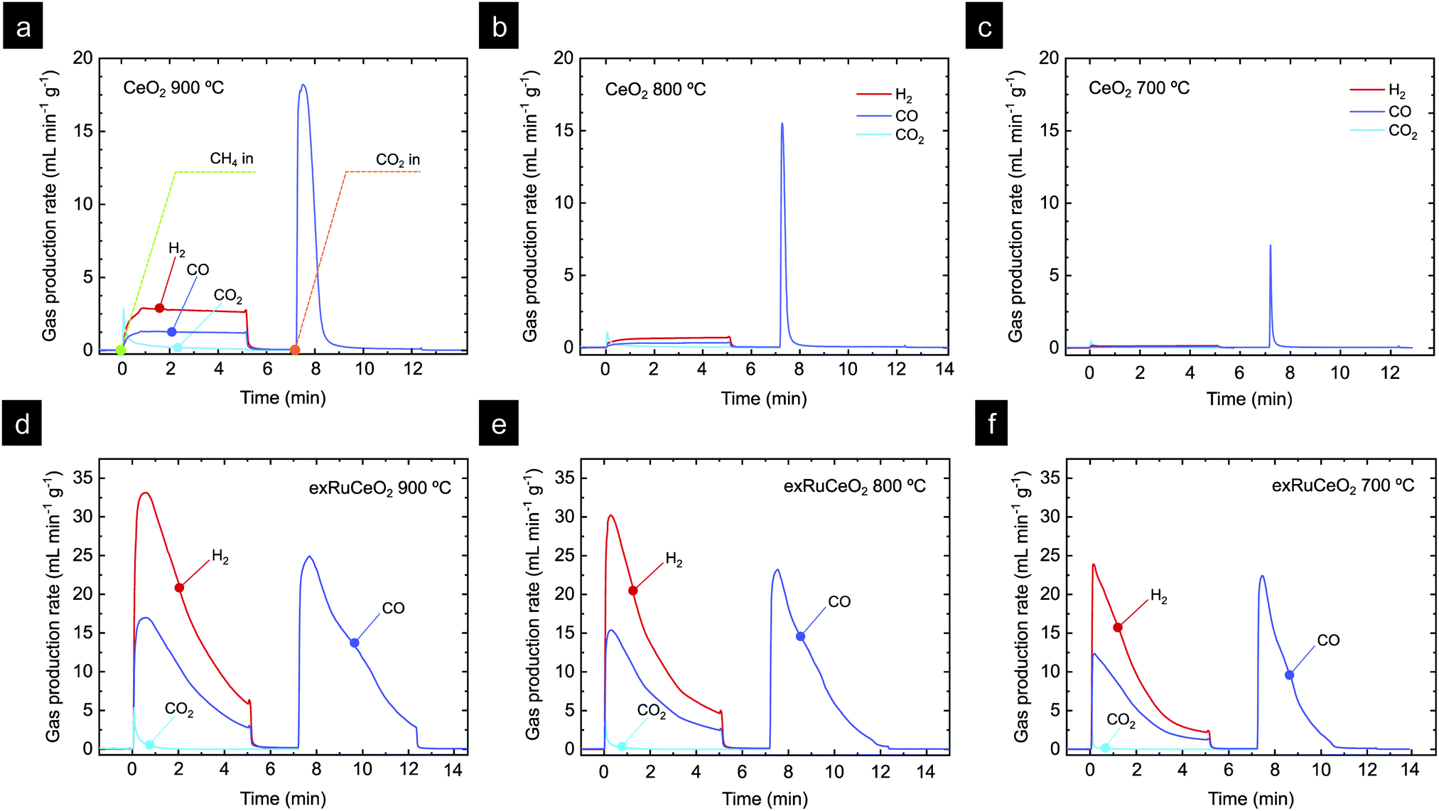 | ||
| Fig. 6 Chemical looping gas production curves for CeO2 at (a) 900 °C, (b) 800 °C and (c) 700 °C, and exRuCeO2 at (d) 900 °C, (e) 800 °C and (f) 700 °C. Each chemical loop consisted of 5 min methane partial oxidation (injection of 5% CH4, total flow 100 mL min−1) and 5 min CO2 splitting (injection of 5% CO2, total flow 100 mL min−1). The exsolution of exRuCeO2 was performed inside a quartz reactor. For that purpose, Ru–CeO2 was reduced under 5% H2 for 2 h at 900 °C. | ||
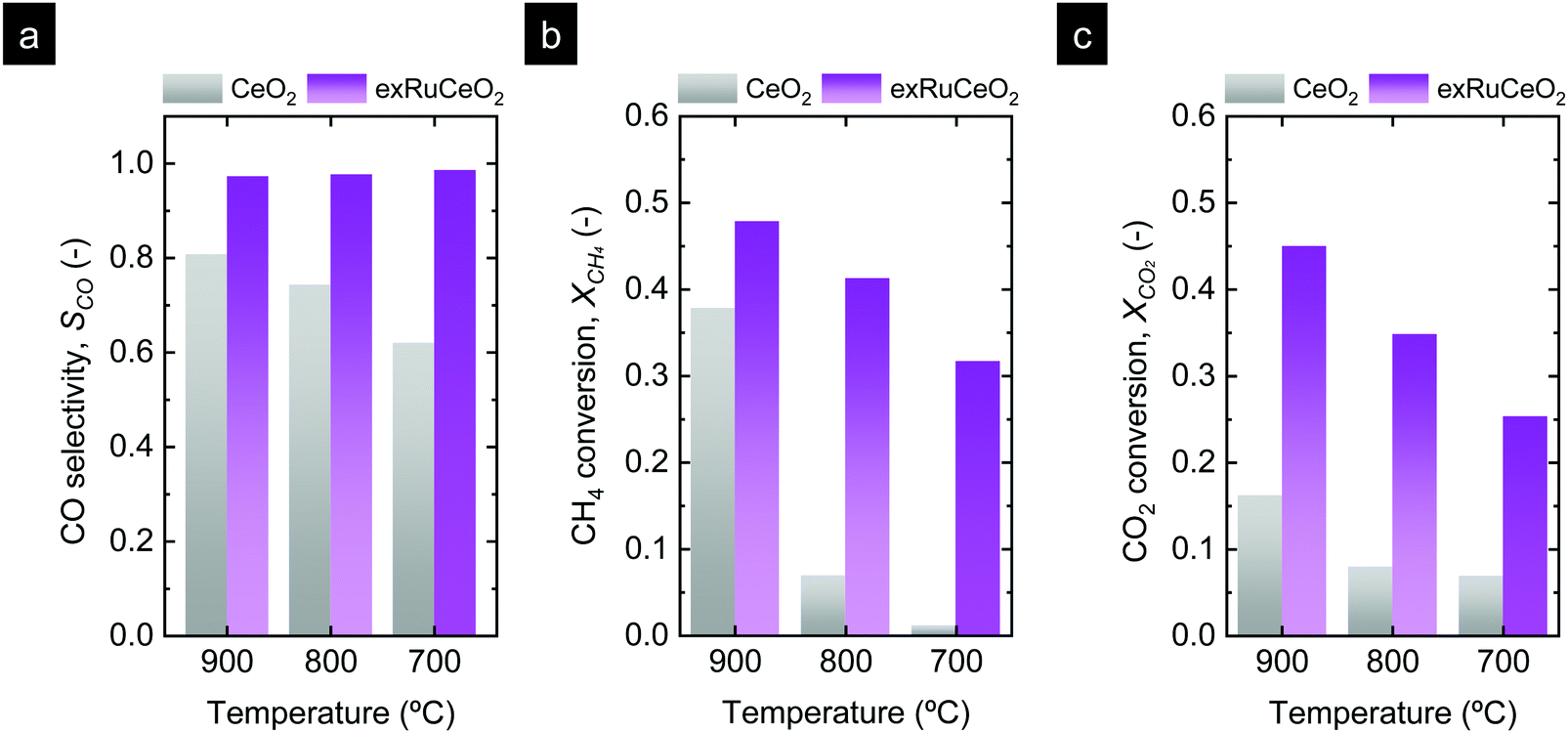 | ||
| Fig. 7 Comparison of (a) selectivity, (b) CH4 conversion during the MPO step, and (c) CO2 conversion during the CO2 splitting step for the two materials tested. | ||
The influence of temperature on the chemical looping reforming activity of CeO2 is depicted in Fig. 6b (reaction at 800 °C) and Fig. 6c (reaction at 700 °C). Here, we would like to note that lowering the process temperature is beneficial to leverage industrial waste heat to drive the endothermic methane partial oxidation reaction.5 However, by lowering the reaction temperature, the driving force for the formation of oxygen vacancies in CeO2 and the activation of CH4 are also decreased since, thermodynamically, oxygen vacancy formation in ceria is favored at higher temperatures.54 This fact implies that lower reduction extents, δ, are achieved during the methane partial oxidation, which directly affects the CO production extent (yield and formation rate) in the subsequent CO2 splitting step (eqn (1) and (2)). This effect is illustrated in Fig. 6b and c, i.e. lowering the reaction temperature drastically diminished the amount of H2 and CO produced in the first step, and hence the CH4 conversion, with peak H2 production rates of 0.76 and 0.18 mL min−1 g−1, denoting one order of magnitude decrease in the syngas production of CeO2 by lowering 200 °C. This temperature decrease also affected SCO, which decreased to 74% and 62% at 800 and 700 °C, respectively. Fig. S4 (ESI†) (a zoom-out of Fig. 6c) reveals that the CO2 production curve is even higher than the H2 and CO ones. In addition, the CO2 splitting rate and CO yield notably decreased at lower temperatures, as an effect of the lower amount of vacancies created in the methane activation step, which directly correlates with the amount of CO produced in the second step. The CO yields obtained were 14.1, 3.5 and 0.5 mL g−1 for 900, 800 and 700 °C, respectively. In addition, for the reaction at 900 °C, there is a fraction of CO that was generated through the Boudouard reaction, in which deposited coke is gasified with CO2, increasing CO yield. In summary, these results provide evidence about the main challenges of CeO2 in chemical looping reforming, i.e. (i) low activity for methane partial oxidation; and (ii) syngas selectivity far from 100%, both being drastically decreased with lowering the process temperature.
Fig. 6d–f show the results of catalytic tests using exRuCeO2 as a redox material at 900, 800 and 700 °C, respectively. By comparing Fig. 6a and d, the benefits of surface functionalization by exsolved Ru nanoparticles become noticeable. At 900 °C the H2 production rate for exRuCeO2 is 33.1 mL min−1 g−1 with a H2 production of 92 mL g−1. In contrast, the values achieved for CeO2 are 2.9 mL min−1 g−1 and 13.70 mL g−1, which are ca. one order of magnitude lower. In addition, the gas production curve when using exRuCeO2 starts with a pronounced peak that progressively decays, which totally differs from the flattened profile exhibited for syngas production with CeO2. The amount of CO produced is 46.6 mL g−1, resulting in a H2:CO ratio of 1.98 close to the stoichiometric 2:1. In comparison CeO2 showed a H2:CO ratio of 2.17 at 900 °C, due to CH4 cracking into H2(g) and C(s). This is indicative of a higher resistance to carbon depositions ascribed to the presence of exsolved nanoparticles, as previously reported in the literature.23Fig. 6a also shows that there is concomitant production of CO2, however, in a minor extent when compared with CO, resulting in a high SCO of 97%. These results highlight the benefits that exsolved Ru nanoparticles impart on improving the methane partial oxidation performance. However, it should be also kept in mind that exRuCeO2 allocates oxygen vacancies prior to the reaction since during the exsolution treatment H2 was utilized to reduce the material and drive the exsolution of Ru nanoparticles. Warren and Scheffe pointed towards surface oxygen vacancies as active sites for methane activation,55 and recently demonstrated how the increase of oxygen vacancies in CeO2, in their case by not reaching full conversion in the previous CO2 splitting oxidation step, could greatly enhance the rate of syngas production.9
The higher syngas yield in the first step is an indicative of a higher extent of reduction for exRuCeO2 when compared with CeO2, triggered by the presence of Ru. As a result, in the subsequent CO2 splitting step, the CO yield (Fig. 6d) was also higher than for CeO2 (Fig. 6a) with 14.1 and 66 mL g−1, respectively. It can be also observed that for exRuCeO2, the CO2 splitting reaction did not achieve equilibrium in the 5 min CO2 injection, opposite to the behavior of CeO2, which reached full oxidation after 2 min exposure.
Similar to what happened to CeO2, lowering the temperature also affected the kinetics and syngas yield, although to a minor extent (Fig. 6e and f). In particular, the performance observed at 700 °C is remarkable (Fig. 6f), which is the temperature closer to the range needed for utilization of industrial waste heat as an energy source. For instance, the peak H2 production rate reaches 23.9 mL min−1 g−1 for exRuCeO2, whereas for CeO2 it is 0.18 mL min−1 g−1. This 2-order of magnitude increase in the syngas production rate at 700 °C illustrates the high catalytic activity of the Ru nanoparticles for the MPO into syngas. In addition, exRuCeO2 displayed SCO ∼ 99% at 700 °C. Fig. 7b shows that methane conversions (XCH4) ∼ 32% can be reached for exRuCeO2 at 700 °C whereas for CeO2 just 1% conversions are observed. Nevertheless, it should be noted here that our experiments were not targeted for reaching higher conversions of CH4 or CO2, which could be improved by shortening the injection time or increasing the solid loading. For the CO2 splitting step, just a slight decrease is observed in the peak production rate when lowering the temperature. That is to say, CO production rates were 24.9, 23.2 and 22.4 mL min−1 g−1 at 900, 800 and 700 °C, respectively. However, since by lowering the temperature the amount of oxygen vacancies generated in the previous reduction step was also decreased, it was observed that CO2 splitting reaction reached equilibrium before the 5 min CO2 injection was complete. That is to say, at 700 °C, CO2 splitting reached equilibrium after 3 min of exposure to CO2 (Fig. 6f) ascribed to a lower amount of oxygen vacancies that should be replenished. This also affected the CO2 conversion values (XCO2) which increased with increasing temperature (Fig. 7c). The highest conversion was for exRuCeO2 at 900 °C with ca. 45%, whereas for CeO2 it was ca. 16% at the same temperature.
2.3. Chemical activity and stability test of exsolved Ru nanoparticles
In the previous section, the benefits of functionalizing the CeO2 oxide surface with Ru nanoparticles became visible, with a remarkable reaction activity improvement when compared with bare CeO2. Now, we assess the stability of the reaction over prolonged cycling at a fixed temperature as well as the stability of the Ru nanoparticles in harsher conditions. For that purpose, we conducted a 20-cycle chemical looping reforming test at 900 °C. The reaction conditions were modified with respect to the previous section, viz., a 10-fold higher concentration of CO2 (50 vol%) was used for the 2nd step. The motivation for the increase of the CO2 partial pressure was 2-fold. The first was in order to assess the reaction in more realistic conditions in which more concentrated CO2 stream would be used. Second, we observed in Fig. 6d that with 5 vol% the CO2 splitting reaction did not reach equilibrium in the given 5 min CO2 injection period. By increasing the CO2 partial pressure faster kinetics are expected,56 achieving full oxidation in the given time. By this way, the material will be fully oxidized in the subsequent reduction step under CH4, and, thus, the kinetic effect provided by the oxygen vacancies acting as active sites at the surface will be suppressed. Raman (Fig. 2b) and XPS analyses (Fig. 5c) proved that exRuCeO2 allocates oxygen vacancies before the first MPO reaction, which Warren and Scheffe showed to be vacancy-mediated.55 The syngas production curves during the 20-cycle chemical looping reforming test are shown in Fig. 8a, in which the syngas (H2 and CO) produced during the MPO and the CO produced during the CO2 splitting step are depicted. It can be observed that over the 20 cycles, the chemical activity of the exRuCeO2 material is preserved, although some differences with respect to the chemical looping test in Fig. 6d are visible. First, regarding the CO production during the CO2 splitting step; with the increase in the vol% of CO2, the peak production rate is greatly enhanced. That is to say, in Fig. 6d we observe a peak production rate of 24.9 mL min−1 g−1 when using 5 vol% of CO2, whereas when increasing the concentration up to 50 vol%, the rate increases up to 189. 9 mL min−1 g−1, which is about a 7-fold increase. However, this high value was not maintained during the whole cycling test, and after a small decrease in the second cycle, it shows stable values at around 156 mL min−1 g−1 from the 6th to the 20th cycle. To put these results into perspective, Ruan et al. reported 168.8 mL min−1 g−1 using 100 vol% CO2 and Ti-doped CeO2 impregnated with metallic Ni.20 In addition, on increasing the vol% of CO2 the reaction reached equilibrium in ca. 1 min (see Fig. S5 in the ESI†). This fact indicates that complete equilibration in CO2via re-oxidation is achieved, and, thus, in the subsequent MPO step, the effect of additional oxygen vacancies – generated upon exsolution – as active sites for the activation of methane could be ruled out. Indeed, when comparing the syngas production curves between the first methane injection and the second, this effect becomes evident. That is to say, during the first MPO reaction, the H2 production is 34.4 mL min−1 g−1, which is very close to the reported value in Fig. 6a wherein the same conditions of 5 vol% of CH4 and 900 °C were employed. However, in the second cycle the peak H2 production rate lowers down to 23.4 mL min−1 g−1, which is ascribed to the initial lack of surface oxygen vacancies that help in activating MPO. Thus, after the first cycle, since high CO2 concentrations are used and, hence, full oxidation achieved, the catalytic improvement for the MPO could be solely ascribed to the exsolved Ru nanoparticles. Importantly, from the 2nd to the 20th cycle the MPO performance was stable (Fig. 8a) with a H2 production rate around 23.4 mL min−1 g−1.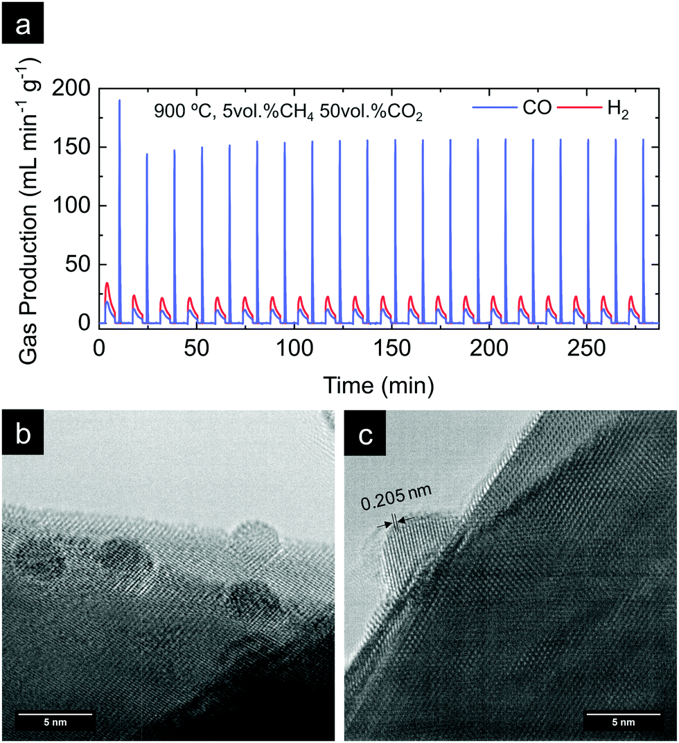 | ||
| Fig. 8 (a) H2 and CO gas production curves obtained from a durability test carried out for exRuCeO2, previously exsolved in a tubular furnace at 900 °C for 2 h under 5% H2. The test consisted of 20 chemical loops, with each of them with first 5 vol% CH4 injection for 5 min, followed by a 2 min purge under pure Ar, and 50 vol% CO2 injection for 5 min. The total flow rate was always kept at 100 ml min−1. (b and c) TEM images of exRuCeO2 after the 20 chemical loops of methane reforming coupled with CO2 splitting, illustrating the stability of the exsolved Ru nanoparticles. In (c) the interplanar distance of the exsolved particle after 20 cycles is illustrated. | ||
Next, we assessed the microstructural stability of the exsolved Ru nanoparticles after the 20-cycle longevity test depicted in Fig. 8a. For that purpose, we analyzed with TEM the materials after reaction (Fig. 8b and c). In Fig. 8b, we provide evidence for the existence of Ru nanoparticles that remained well dispersed over the oxide surface after the multi-cycle treatment at high temperatures. Since the images were taken after the last CO2 splitting step, this also proves that the exsolved Ru nanoparticles are not dissolved back into the lattice under these experimental conditions used in the oxidation step. This is probably due to the short exposure (5 min) to a less oxidative atmosphere (CO2) when compared to air, which is the gas used in re-dissolution treatments. Thus, under these oxidative conditions there is not enough driving force to produce the dissolution of the exsolved Ru nanoparticles back to the ceria backbone. This fact was previously reported with Co exsolution in La0.6Sr0.4Cr0.8Co0.2O3 perovskites.32 The nanoparticles of 4–5 nm remained well-dispersed and anchored to the oxide backbone, which prevented nanoparticle agglomeration. Fig. 8c provides further evidence of the level of anchoring. The interplanar distance of the exsolved nanoparticle was determined to be equal to 0.205 nm, which corresponds to the (101) orientation in metallic Ru, which further corroborates the nature of the exsolved nanoparticles.
The X-ray diffractogram of exRuCeO2 before and after the 20 chemical looping reforming cycles is depicted in Fig. 9a. After cycling, the material presented the peaks associated with the fluorite crystal structure. However, the calculated cubic lattice parameter was 5.422 Å, whereas before reaction it was 5.413 Å, indicating lattice expansion upon cycling, returning to lattice volume values similar to the material before exsolution (a = 5.421 Å for Ru–CeO2). Raman spectroscopy was employed to further analyze the structural changes after multiple cycling (Fig. 9b and c). Fig. 9b reveals that after cycling the F2g vibration is still the main component. However, as observed in the zoom-out area depicted in Fig. 9c, the F2g shifted towards lower wavenumbers, with respect to the freshly exsolved material. That is to say, after 20 cycles the F2g peak value moved to 463.1 cm−1, whereas before reaction it was 464.5 cm−1, displacement that confirms the lattice expansion observed by XRD analysis.
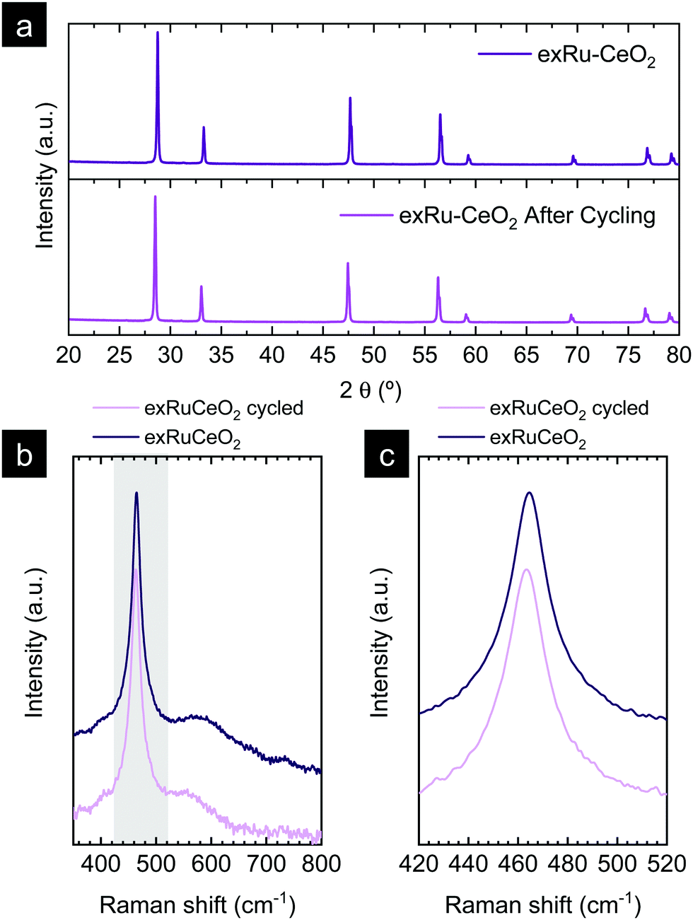 | ||
| Fig. 9 (a) XRD diffractograms comparing exRuCeO2 before and after the 20-cycle chemical looping reforming test. (b) Raman spectra comparison of exRuCeO2 before and after 20 cycles. They grey-shaded region is zoomed out in (c) to show the shift of the F2g peak towards lower Raman shift values. The Raman spectra were collected with a 785 cm−1 laser. | ||
In summary, in this section we proved both the microstructural and chemical stability of the Ru nanoparticles over prolonged cycling at high temperatures, which remarks the key benefits of applying exsolution in high temperature thermocatalytic processes.
3. Conclusions
In this work, we have synthesized CeO2 decorated with Ru nanoparticles of ca. 5 nm via the exsolution method and tested its activity for chemical looping reforming of methane coupled with CO2 splitting, to address the main limitations that bare CeO2 presents in this process. With TEM, EDX and XPS we provide proof of Ru nanoparticle exsolution and anchorage on CeO2 for the first time, which were well dispersed all over the oxide surface. The chemical-looping reforming activity was tested and compared against reference – undoped – CeO2, observing a remarkable increase in the syngas yield and production rate as well as carbon monoxide selectivity of 99% at 700 °C. Particularly remarkable is the syngas production result at such temperature, which matches perfectly operation utilizing industrial waste heat. That is to say, at 700 °C, a peak H2 production rate of 23.9 mL min−1 g−1 was obtained for the material decorated with exsolved Ru nanoparticles, whereas for bare CeO2 it was just 0.18 mL min−1 g−1, which is two orders of magnitude less. Finally, the durability of the process was tested for 20 consecutive chemical loops denoting the remarkable stability of the morphology of exsolved nanoparticles after prolonged cycling. In summary, the findings presented here confirm the robustness of CeO2-surface-anchored exsolved Ru nanoparticles as catalysts in high temperature thermochemical processes.4. Experimental methods
4.1. Material synthesis
CeO2 and Ru0.01Ce0.99O2 (Ru–CeO2) were synthesized by a modified version of the Pechini method. Cerium(III)nitrate (Ce(NO3)3·6H2O, 99%; Sigma Aldrich-Merck) and ruthenium(III)nitrosyl nitrate solution (Ru(NO)(NO3)x(OH)y, x + y = 3, 1.5% Ru; Sigma Aldrich-Merck) were dissolved in an aqueous solution of citric acid (CA, 99%; Sigma Aldrich-Merck) at 60 °C under constant stirring for 3 h, using a metal precursor:CA molar ratio of 1:1.5. Afterward, ethylene glycol (EG, 99%; Sigma Aldrich-Merck) was added to the mixture to a CA:EG ratio of 2/3 wt% and the temperature was increased to 80 °C for 2 h. After most of the solution was evaporated, it was transferred to a drying oven and heated at 220 °C overnight, during which gelification and calcination of the gel took place. Then, the dry powder was ground into a fine powder using an agate mortar and calcined at 1000 °C for 10 h to obtain the fluorite phase. Nanoparticle exsolution on Ru–CeO2 was performed in a horizontal tubular furnace at 900 °C, during 2 h under 5% H2/Ar flow, unless otherwise specified in the text.
4.2. Physicochemical characterization
X-ray diffractometry (XRD) was performed utilizing a PANalytical CubiX fast diffractometer using CuKα1,2 radiation and a X'Celerator detector in Bragg–Brentano geometry. XRD patterns were recorded in the 2θ range 20° to 90° and analyzed using the software X'Pert Highscore Plus.X-ray photoelectron spectra were collected by using a SPECS spectrometer equipped with a Phibos 150 MCD-9 detector and by using a non-monochromatic AlKa (1486.6 eV) X-ray source and charge compensation by means of additional electron flow. Spectra were recorded by using an analyzer pass energy of 50 eV and an X-ray power of 100 W under an operating pressure of 10−9 mbar. During data processing of the XPS spectra, the binding energy (BE) values were referenced to C1s (peak at BE = 248.8 eV). Spectra treatment was performed using CasaXPS processing software.
Raman spectroscopy was performed using a Renishaw Raman spectrometer. Analyses were conducted at room temperature with a 785 nm laser equipped with an Olympus microscope and a CCD detector.
The morphology of the synthesized oxides was analyzed via scanning electron microscopy (SEM) using a GeminiSEM 500 from Zeiss and transmission electron microscopy (TEM) using a JEM 2100F 200 kV field emission microscope equipped with a Gatan OneView camera. Energy dispersive X-ray spectroscopy elemental point scan analyses were conducted using EDS X-Max 80 de Oxford Instruments, with a 127 eV resolution.
The Micromeritics system was used to carry out temperature-programmed reduction (TPR). 100 mg of sample was pelletized and degassed under Ar flow for 1 h and then was subjected to reduction under H2/Ar (1/9) flow, with a heating rate of 10 °C min−1 until 950 °C. H2 consumption was measured by using a TCD.
4.3. Chemical looping reforming test
Chemical looping reforming of methane coupled with CO2 splitting was carried out in a fixed-bed reactor setup. The reactor consisted of a quartz tube of ½ inch inner diameter placed inside a tubular vertical electrical furnace. The oxide samples (0.265 g) were placed over a quartz frit located at half of the quartz tube (total length 41 cm). The temperature was controlled with a K-type thermocouple in contact with the oxide bed and covered by a quartz shield. For the reaction tests, the materials were pressed into pellets, crushed and sieved for the size between 200 and 400 μm. The gas production was monitored using a Thermostar mass spectrometer from Pfeiffer, which was calibrated by flowing known gas concentrations before each reaction. In a typical experiment, the temperature was raised to 900 °C under an Ar (Praxair) atmosphere (100 mL min−1). Then, the materials were pretreated under 5% H2 balanced with Ar atmosphere for 2 h to drive the nanoparticle exsolution, unless otherwise specified. Afterward, each chemical loop consisted of 5 min injections of first, 5% CH4, and second, 5% CO2, both balanced in Ar. Between both injections, Ar was flowed to purge the reactor of reactive gases for 2 min. The gas bottles were of 10% CH4 balanced in Ar and 15% CO2 balanced in Ar.For the longevity test consisting of 20 chemical loops, a thinner quartz tube was used with an internal diameter of 0.7 cm. In addition, for the oxidation step a stream of 50 vol% of CO2 was used utilizing a 100% CO2 gas bottle and a total gas flow of 100 mL min−1.
CO2 and CO m/z signal overlapping was corrected through the following equation according to Sastre et al.57
 | (5) |
The carbon monoxide selectivity (SCO) and CH4 and CO2 conversion (XCH4 and XCO2 respectively) were calculated as follows, where nCO, nCH4 and nCO2 are the moles of CO, CH4 and CO2 as integrated with time for the CO, CH4 and CO2 profiles respectively:
 | (6) |
 | (7) |
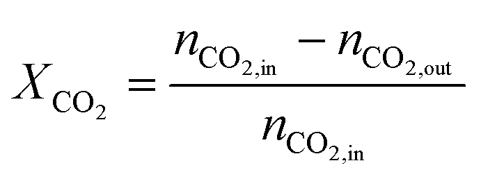 | (8) |
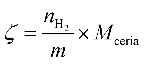
The oxygen supply capacity was calculated using the following equation, adapted from ref. 30:
 | (9) |
 is the H2 moles consumed by the oxide determined by TPR analyses, m is the mass of the sample measured by TPR, and Mceria is the molecular mass of the cerium oxides tested.
Conflicts of interest
The authors declare no conflict of interest.Acknowledgements
AJC and MB would like to acknowledge the support of Juan de la Cierva fellowships by the Spanish Ministry of Science (grant numbers FJCI-2017-33967 and IJCI-2017-34110). We acknowledge the support of the Electronic Microscopy Service of the Universitat Politècnica de València.References
- A. Thursfield, A. Murugan, R. Franca and I. S. Metcalfe, Energy Environ. Sci., 2012, 5, 7421–7459 RSC.
- X. Zhu, F. Donat, Q. Imtiaz, C. R. Müller and F. Li, Energy Environ. Sci., 2020, 14, 112 Search PubMed.
- J. Garcia-Fayos, J. M. Serra, M. W. J. Luiten-Olieman and W. A. Meulenberg, Gas separation ceramic membranes, 2020 Search PubMed.
- A. J. Carrillo, J. L. M. Rupp and J. M. Coronado, in Energy Storage and Conversion Materials, ed. S. J. Skinner, The Royal Society of Chemistry, Inorganic, 2020, pp. 136–187 Search PubMed.
- V. P. Haribal, X. Wang, R. Dudek, C. Paulus, B. Turk, R. Gupta and F. Li, Adv. Energy Mater., 2019, 9, 1901963 CrossRef CAS.
- P. T. Krenzke, J. R. Fosheim and J. H. Davidson, Sol. Energy, 2017, 156, 48–72 CrossRef CAS.
- C. Agrafiotis, H. Von Storch, M. Roeb and C. Sattler, Renewable Sustainable Energy Rev., 2014, 29, 656–682 CrossRef CAS.
- J. Zhang, V. Haribal and F. Li, Sci. Adv., 2017, 3, e1701184 CrossRef PubMed.
- K. J. Warren, R. J. Carrillo, B. Greek, C. M. Hill and J. R. Scheffe, Energy Technol., 2020, 8, 2000053 CrossRef CAS.
- R. J. Carrillo and J. R. Scheffe, Sol. Energy, 2017, 156, 3–20 CrossRef CAS.
- K. J. Warren, J. Reim, K. Randhir, B. Greek, R. Carrillo, D. W. Hahn and J. R. Scheffe, Energy Technol., 2017, 5, 2138–2149 CrossRef CAS.
- M. Welte, K. Warren, J. R. Scheffe and A. Steinfeld, Ind. Eng. Chem. Res., 2017, 56, 10300–10308 CrossRef CAS PubMed.
- S. Chuayboon, S. Abanades and S. Rodat, Chem. Eng. J., 2019, 356, 756–770 CrossRef.
- Y. Zheng, X. Zhu, H. Wang, K. Li, Y. Wang and Y. Wei, J. Rare Earths, 2014, 32, 842–848 CrossRef CAS.
- X. Gao, A. Vidal, A. Bayon, R. Bader, J. Hinkley, W. Lipiński and A. Tricoli, J. Mater. Chem. A, 2016, 4, 9614–9624 RSC.
- Y. Chen, X. Zhu, K. Li, Y. Wei, Y. Zheng and H. Wang, ACS Sustainable Chem. Eng., 2019, 7, 15452–15462 CrossRef CAS.
- X. Gao, G. Liu, Y. Zhu, P. Kreider, A. Bayon, T. Gengenbach, T. Lu, Y. Liu, J. Hinkley, W. Lipiński and A. Tricoli, Nano Energy, 2018, 50, 347–358 CrossRef CAS.
- X. Gao, I. Di Bernardo, P. Kreider, T. Tran-Phu, X. Cai, N. Wang, Y. Zhu, M. B. Venkataraman, J. Lipton-Duffin, A. Bayon, W. Lipiński and A. Tricoli, ACS Catal., 2019, 9880–9890 CrossRef CAS.
- M. Fathi, E. Bjorgum, T. Viig and O. Rokstad, Catal. Today, 2000, 63, 489–497 CrossRef CAS.
- C. Ruan, Z.-Q. Huang, J. Lin, L. Li, X. Liu, M. Tian, C. Huang, C.-R. Chang, J. Li and X. Wang, Energy Environ. Sci., 2019, 12, 767–779 RSC.
- T. W. Hansen, A. T. DeLaRiva, S. R. Challa and A. K. Datye, Acc. Chem. Res., 2013, 46, 1720–1730 CrossRef CAS.
- D. Neagu, G. Tsekouras, D. N. Miller, H. Menard and J. T. Irvine, Nat. Chem., 2013, 5, 916–923 CrossRef CAS.
- D. Neagu, T. S. Oh, D. N. Miller, H. Menard, S. M. Bukhari, S. R. Gamble, R. J. Gorte, J. M. Vohs and J. T. Irvine, Nat. Commun., 2015, 6, 8120 CrossRef PubMed.
- J. T. S. Irvine, D. Neagu, M. C. Verbraeken, C. Chatzichristodoulou, C. Graves and M. B. Mogensen, Nat. Energy, 2016, 1, 15014 CrossRef CAS.
- B. Hua, M. Li, Y. F. Sun, J. H. Li and J. L. Luo, ChemSusChem, 2017, 10, 3333–3341 CrossRef CAS PubMed.
- K. Kousi, D. Neagu, L. Bekris, E. I. Papaioannou and I. S. Metcalfe, Angew. Chem., Int. Ed., 2020, 59, 2510–2519 CrossRef CAS PubMed.
- M. A. Naeem, P. M. Abdala, A. Armutlulu, S. M. Kim, A. Fedorov and C. R. Müller, ACS Catal., 2020, 10, 1923–1937 CrossRef CAS.
- Y. J. Wong, M. K. Koh, N. F. Khairudin, S. Ichikawa, Y. Morikawa and A. R. Mohamed, ChemCatChem, 2019, 11, 5593–5605 CrossRef CAS.
- S. Vecino-Mantilla, P. Gauthier-Maradei, M. Huvé, J. M. Serra, P. Roussel and G. H. Gauthier, ChemCatChem, 2019, 11, 4631–4641 CrossRef CAS.
- K. Kousi, D. Neagu, L. Bekris, E. Calì, G. Kerherve, E. I. Papaioannou, D. J. Payne and I. S. Metcalfe, J. Mater. Chem. A, 2020, 8, 12406–12417 RSC.
- G. Dimitrakopoulos, A. F. Ghoniem and B. Yildiz, Sustainable Energy Fuels, 2019, 3, 2347–2355 RSC.
- A. J. Carrillo, K. J. Kim, Z. D. Hood, A. H. Bork and J. L. M. Rupp, ACS Appl. Energy Mater., 2020, 1–34 CAS.
- T. Montini, M. Melchionna, M. Monai and P. Fornasiero, Chem. Rev., 2016, 116, 5987–6041 CrossRef CAS PubMed.
- Y. Chen, B. DeGlee, Y. Tang, Z. Wang, B. Zhao, Y. Wei, L. Zhang, S. Yoo, K. Pei, J. H. Kim, Y. Ding, P. Hu, F. F. Tao and M. Liu, Nat. Energy, 2018, 3, 1042–1050 CrossRef CAS.
- X. Shen, T. Chen, S. R. Bishop, N. H. Perry, H. L. Tuller and K. Sasaki, J. Power Sources, 2017, 370, 122–130 CrossRef CAS.
- J. M. Serra, J. F. Borrás-Morell, B. García-Baños, M. Balaguer, P. Plaza-González, J. Santos-Blasco, D. Catalán-Martínez, L. Navarrete and J. M. Catalá-Civera, Nat. Energy, 2020, 5, 910–919 CrossRef CAS.
- R. D. Shannon, Acta Crystallogr., Sect. A: Cryst. Phys., Diffr., Theor. Gen. Crystallogr., 1976, 32, 751–767 CrossRef.
- P. Singh and M. S. Hegde, Chem. Mater., 2009, 21, 3337–3345 CrossRef CAS.
- S. Sharma, Z. Hu, P. Zhang, E. W. McFarland and H. Metiu, J. Catal., 2011, 278, 297–309 CrossRef CAS.
- R. Schmitt, A. Nenning, O. Kraynis, R. Korobko, A. I. Frenkel, I. Lubomirsky, S. M. Haile and J. L. M. Rupp, Chem. Soc. Rev., 2020, 49, 554–592 RSC.
- E. Sediva, A. J. Carrillo, C. E. Halloran and J. L. M. Rupp, ACS Appl. Energy Mater., 2021, 4, 1474–1483 CrossRef CAS.
- H. Han, J. Park, S. Y. Nam, K. J. Kim, G. M. Choi, S. S. P. Parkin, H. M. Jang and J. T. S. Irvine, Nat. Commun., 2019, 10, 1471 CrossRef PubMed.
- C. L. Muhich, J. Phys. Chem. C, 2017, 121, 8052–8059 CrossRef.
- C. Solís, M. Balaguer and J. M. Serra, Membranes, 2020, 10, 1–16 Search PubMed.
- M. Balaguer, C. Solís and J. M. Serra, Chem. Mater., 2011, 23, 2333–2343 CrossRef CAS.
- M. Balaguer, C. Solís, S. Roitsch and J. M. Serra, Dalton Trans., 2014, 43, 4305–4312 RSC.
- Y. Gao, D. Chen, M. Saccoccio, Z. Lu and F. Ciucci, Nano Energy, 2016, 27, 499–508 CrossRef CAS.
- J. Spring, E. Sediva, Z. D. Hood, J. C. Gonzalez-Rosillo, W. O’Leary, K. J. Kim, A. J. Carrillo and J. L. M. Rupp, Small, 2020, 16, 2003224 CrossRef CAS PubMed.
- D. Neagu, V. Kyriakou, I. Roiban, M. Aouine, C. Tang, A. Caravaca, K. Kousi, I. Schreur-Piet, I. S. Metcalfe, P. Vernoux, M. C. M. van de Sanden and M. N. Tsampas, ACS Nano, 2019, 13, 12996–13005 CrossRef CAS PubMed.
- J. Moulder, W. Stickle, P. Sobol and K. Bomben, Handbook of X-ray photoelectron spectroscopy, 1992 Search PubMed.
- C. Yang, X. Yu, S. Heißler, A. Nefedov, S. Colussi, J. Llorca, A. Trovarelli, Y. Wang and C. Wöll, Angew. Chem., Int. Ed., 2017, 56, 375–379 CrossRef CAS PubMed.
- E. Bêche, P. Charvin, D. Perarnau, S. Abanades and G. Flamant, Surf. Interface Anal., 2008, 40, 264–267 CrossRef.
- J. F. Moulder, Handbook of X-ray photoelectron spectroscopy, physical electronics, 1995 Search PubMed.
- P. T. Krenzke, J. R. Fosheim, J. Zheng and J. H. Davidson, Int. J. Hydrogen Energy, 2015, 41, 12799–12811 CrossRef.
- K. J. Warren and J. R. Scheffe, J. Phys. Chem. C, 2019, 123, 13208–13218 CrossRef CAS.
- S. Ackermann, L. Sauvin, R. Castiglioni, J. L. M. Rupp, J. R. Scheffe and A. Steinfeld, J. Phys. Chem. C, 2015, 119, 16452–16461 CrossRef CAS PubMed.
- D. Sastre, D. P. Serrano, P. Pizarro and J. M. Coronado, J. CO2 Util., 2019, 31, 16–26 CrossRef CAS.
Footnote |
| † Electronic supplementary information (ESI) available. See DOI: 10.1039/d1ma00044f |
| This journal is © The Royal Society of Chemistry 2021 |