DOI:
10.1039/D0MA00905A
(Paper)
Mater. Adv., 2021,
2, 793-803
Ammonia synthesis using Fe/BZY–RuO2 catalysts and a caesium dihydrogen phosphate-based electrolyte at intermediate temperatures†
Received
20th November 2020
, Accepted 29th December 2020
First published on 7th January 2021
Abstract
In this study, we developed an Fe2O3/BZY (yttrium-doped barium zirconate)–RuO2 (Fe/BZY–RuO2) cathode catalyst, which was applied to the electrochemical synthesis of NH3 using a proton-conducting electrolyte, CsH2PO4/SiP2O7, at 220 °C and ambient pressure. The highest faradaic efficiency of 7.1% was achieved at −0.4 V (vs. open-circuit voltage (OCV)) and the highest NH3 yield rate of 4.5 × 10⁻¹⁰ mol (s cm2)−1 was achieved at −1.5 V (vs. OCV). We also successfully detected N2H4 and NH3 at −0.2 V (vs. OCV), which indicated that the N2 reduction proceeded via an associative mechanism. A potentiostatic pulse experiment was conducted under a feed of Ar or N2 in the cathode at different applied voltages to investigate the N2 reduction reaction (NRR) mechanism. A model was developed to fit the current response of the potentiostatic pulse experiment, which comprised the decomposition of adsorbed intermediates on the surface of the cathode catalyst, diffusion of H in the cathode catalyst, and an electrical double layer. The results revealed that the rate constant estimated by the model for the decomposition of intermediates, such as NH or N2H, was lowest at −0.2 V, where N2H4 was detected. The fitting results also indicated that the NRR proceeded via an associative mechanism at lower applied voltages, while a dissociative mechanism dominated at higher applied voltages.
Introduction
The conventional Haber–Bosch process, which uses iron-based catalysts to produce NH3, is one of the most important heterogeneous catalytic processes, and is still in use today. It requires high temperatures (400–500 °C) and pressures (50–200 bar), resulting in the consumption of more than 1% of the primary energy supplies of the world and consequently the generation of more than 400 Mt CO2.1 Electrochemical N2 reduction has attracted considerable attention as an alternative because it involves mild reaction conditions and NH3 is produced directly from N2 and water using a renewable energy source.2 However, the greatest challenge is that the production of H2 from protons at the electrode has priority over NH3 formation, which leads to a low faradaic efficiency. It is difficult to activate N2 at low temperatures (<100 °C), while high temperatures (>500 °C) result in the decomposition of the generated NH3. Thus, an intermediate temperature range (100–500 °C) is preferred for the electrochemical synthesis of NH3. In addition, at temperatures lower than 200 °C, the total Gibbs energy input per NH3 production is lower for the above-described direct electrochemical synthesis than that for the combined water electrolysis and Haber–Bosch process system. Consequently, the direct electrochemical synthesis of NH3 at temperatures <200 °C is an energy-efficient process for the production of NH3.
Because N2 is activated by the catalyst, the type of cathode catalyst used determines the efficiency of the direct electrochemical synthesis of NH3. Ni mesh,3,4 Pt/C,5 and Ru/C5 have been reported as cathode catalysts for use at a temperature of approximately 200 °C. Bicer and Dincer reported the use of a Ni mesh cathode and nano-Fe2O3 particles suspended in a molten NaOH–KOH mixture as the electrolyte for an electrolytic cell, which produced NH3 from N2 and H2 at 200 °C3 at a maximum formation rate of 4.41 × 10⁻⁹ mol (s cm2)−1 with a faradaic efficiency of 14.17%.3 Using a Ru/C cathode and CsH2PO4/SiP2O7 electrolyte for the synthesis of NH3 from N2 and H2O at 220 °C through solid-state electrolysis, a maximum reaction rate of 1.9 × 10⁻¹¹ mol (s cm2)−1 and a faradaic efficiency of 0.06% was achieved.5 Generally, the N2 reduction reaction (NRR) mechanism can be categorized into two pathways: dissociative and associative. In the dissociative pathway, the NN triple bond is first cleaved to produce N*, while in the associative pathway, H first reacts with N2 to produce NNH*.6 If the N–N bond is retained during the addition of H, N2H4 will be produced. As suggested by DFT calculation results, the associative mechanism is usually the most favourable pathway for the electrochemical synthesis of NH3.7,8 However, most experimental studies do not report the formation of N2H4,9–13 with the exception of the study conducted by Bao et al.14 This might be because N–N bond dissociation occurs rapidly in intermediates such as NNH2* to produce NH3, owing to the large free energy change that occurs over widely used precious metal cathode catalysts. Consequently, the apparent production rate of N2H4 was negligible. Singh et al. reported that for low N2 binding energies on transition metal surfaces, thermochemical N–N bond dissociation has a lower activation barrier than that of the associative NRR in the electrochemical pathway.17 This was established using calculations by assuming an appropriate N–N transition-state scaling. These results might also explain the lack of N2H4 detection.
In this study, a novel iron-based composite, a reduced α-Fe2O3/BZY (yttrium-doped barium zirconate), was used as a cathode catalyst for the electrolytic synthesis of NH3 from N2 and H2 at 220 °C in a double-chamber cell. The reduced α-Fe2O3/BZY (Fe/BZY) catalyst was also combined with RuO2 and tested as a cathode catalyst for the electrolytic synthesis of NH3 from N2 and water vapor at 220 °C in a double-chamber cell. Fe/BZY exhibits electrical conductivity and should possess proton conductivity and catalytic activity for N2 reduction; these are the desired properties for a cathode catalyst applied in the electrolytic synthesis of NH3 (Table S1, ESI†). A Pt anode and CsH2PO4/SiP2O7 electrolyte15 were used for the electrochemical synthesis of NH3 at 220 °C and atmospheric pressure. There are three requirements for the electrocatalytic NRR to achieve a high activity and selectivity towards NH3: (i) the catalysts should bind strongly to N2, (ii) a large reduction potential should be applied at which the NRR mechanism is in its irreversible limit,16 and (iii) a nonaqueous electrolyte, with a lowered proton donor activity that limits the proton availability at the electrode surface and consequently improves the selectivity towards NH3, should be used.17,18 The electrode catalysts and electrolyte employed in this study meets these requirements. To elucidate the NRR pathway over the electrode catalysts developed in this study, the intermediates on the cathode catalyst surface were analyzed by potentiostatic pulse experiments under dry N2 or Ar atmosphere by applying a variety of voltages. To interpret the current response of the potentiostatic experiments, a model comprising adsorbed intermediate decomposition, H diffusion in the catalyst, and an electrical double layer was developed.
Experimental
Preparation of reduced α-Fe2O3/BZY19
The yttrium-doped barium zirconate (BaZr0.8Y0.2O3−σ) powder was prepared by a conventional solid-state reaction. The reagents used were BaCO3 (98% purity, Wako Pure Chemical Industries Ltd, Osaka, Japan), Y2O3 (99.9% purity, Wako Pure Chemical Industries Ltd, Osaka, Japan), and ZrO2 (98% purity, Wako Pure Chemical Industries Ltd, Osaka, Japan). The materials were mixed in stoichiometric quantities and ball milled in ethanol overnight. After drying, the precursor was calcined at 1400 °C for 12 h to yield the BZY powder. The BZY powder and α-Fe2O3 (20–40 nm, Wako Pure Chemical Industries Ltd, Tokyo, Japan) were mixed in a weight ratio of 1![[thin space (1/6-em)]](https://www.rsc.org/images/entities/char_2009.gif) :4 and ball milled in ethanol overnight. After drying, the mixture was sintered at 1300 °C for 12 h to form an α-Fe2O3/BZY composite. The resultant α-Fe2O3/BZY composite was reduced in H2 atmosphere at 500 °C for 1 h and cooled to 25 °C under N2.
:4 and ball milled in ethanol overnight. After drying, the mixture was sintered at 1300 °C for 12 h to form an α-Fe2O3/BZY composite. The resultant α-Fe2O3/BZY composite was reduced in H2 atmosphere at 500 °C for 1 h and cooled to 25 °C under N2.
Preparation of the reduced α-Fe2O3/BZY and RuO2 mixtures
The reduced α-Fe2O3/BZY was mixed with RuO2 (Practical Grade, Wako Pure Chemical Industries Ltd, Osaka, Japan) and ground to fabricate the cathode materials.
Preparation of CsH2PO4/SiP2O75
CsH2PO4 was prepared using Cs2CO3 (Wako 1st Grade, Wako Pure Chemical Industries Ltd, Osaka, Japan) and H3PO4 (85 wt% in water, Sigma-Aldrich Co. LLC, Missouri, USA) in stoichiometric quantities. After dissolution in distilled water, the precursor was dried at 120 °C overnight. SiP2O7 was prepared from SiO2 (99.9% purity, Wako Pure Chemical Industries Ltd, Osaka, Japan) and H3PO4 as follows: SiO2 and H3PO4 were mixed in a molar ratio of 1:2.5, and heated at 200 °C for 3 h. After drying at 100 °C for 24 h, the precursor was ground into a powder and heated at 122 °C for 24 h. Finally, the powder was calcined at 700 °C for 3 h to attain the SiP2O7 phase. Subsequently, the prepared CsH2PO4 and SiP2O7 were mixed in a molar ratio of 1:1 and ground to form the CsH2PO4/SiP2O7 composite.
Preparation of electrolysis cells
The CsH2PO4/SiP2O7 powder was pressed into a ∅ 20 mm disk. The reduced α-Fe2O3/BZY (0.075 g) and RuO2 (0.075 g) powders were mixed and loaded on the cathode side of the CsH2PO4/SiP2O7 disk and pressed at a pressure of 20 MPa for 10 min. Porous carbon paper (∅ 10 mm, TGP-H-120, Toray Industries, Inc., Tokyo, Japan) was used as the current collector on the cathode side. A Pt/C loaded carbon paper of ∅ 10 mm (Pt loading of 1 mg cm−2, Miclab, Kanagawa, Japan) was used as the anode catalyst. Pt wires connected to the Pt mesh or Pt/C were used as the terminal on the anode side, while the Pt wires connected to the carbon paper acted as the terminal on the cathode side. Polytetrafluoroethylene (PTFE) sheet (Gore Hyper-Sheet Gasket, W. L. Gore & Associate, Inc., Delaware, USA) layers with an appropriate thickness were used as the gas seal. The two-chamber reactor setup is illustrated in Fig. 1.
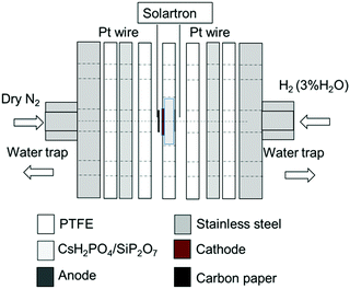 |
| | Fig. 1 Experimental setup for electrochemical synthesis of NH3. | |
Characterization
X-ray diffraction was performed at 100 kV and 40 mA in the 2θ range of 20–80° (XRD, Rigaku RINT 2400). The cross-sectional morphologies of the electrolysis cells were observed by scanning electron microscopy (SEM, Hitachi S-4700, Tokyo, Japan) and energy dispersive X-ray spectroscopy (EDX, Super Xerophy, Horiba, Kyoto, Japan). Temperature-programmed reduction (TPR) experiments were performed in a flow system (Quantachrome, CHEMBET-3000, Florida, USA). To confirm that the addition of the Ru species could suppress the oxidation of Fe, the samples were pretreated at 220 °C for 30 min in Ar at a flow rate of 50 mL min−1 and heating rate of 10 °C min−1 and cooled to room temperature. After flushing with diluted H2 (5% H2 in Ar) at a flow rate of 50 mL min−1 for 1 h, the samples were heated to 220 °C at a heating rate of 10 °C min−1 and reduced for 1 h. After flushing with Ar at a flow rate of 50 mL min−1 for 30 min, the samples were oxidised in diluted O2 (5% O2 in He) at a flow rate of 50 mL min−1 for 30 min and cooled to room temperature in Ar. The samples were again flushed with diluted H2 and heated to 1000 °C. The proton conductivity of the cell was evaluated by alternating current impedance measurements from 1 MHz to 0.05 Hz, with an AC amplitude of 20 mV under 3%-humidified H2 (or 20%-humidified Ar) on the anode side and dry N2 on the cathode side (Solartron 1260, Solartron Instruments, Hampshire, UK). Humidified H2 (3% H2O) and Ar (20% H2O) were obtained by bubbling H2 or Ar gas into distilled water in a water bath at room temperature and at 60 °C, respectively. The potentiostatic pulse experiment,20,21 was conducted by applying bias voltages for 400 s and then stepping to an open circuit voltage (OCV) (SP 300, Bio-Logic, Seyssinet-Pariset, France).
Pretreatment of the cell
The cell was heated from 25 °C to 220 °C at a heating rate of 2.8 °C min−1, with a gas flow of dry N2 on the cathode side and dry Ar on the anode side from 25 °C to 120 °C. From 120 °C to 220 °C, humidified H2 gas was fed to the anode. In the steady state, a voltage of −2 V (vs. OCV) was applied to the cell for 1 h to reduce RuO2.
Blank experiments using open circuit conditions and testing
The following three blank experiments were conducted at 220 °C at OCV conditions before performing the reaction tests. Blank experiment 1 was conducted using a gas flow of 3%-humidified H2 on the anode side and dry N2 on the cathode side. Blank experiment 2 was performed with a gas flow of 20%-humidified Ar on the anode side and dry Ar on the cathode side. Blank experiment 3 was conducted with a gas flow of 20%-humidified Ar on the anode side and dry N2 on the cathode side. Electrolysis was performed under the same conditions as blank experiment 1. A direct current voltage vs. OCV was applied between the anode and cathode under potentiostatic conditions. The total gas flow rate was kept constant at 25 mL (STP) min−1 on both sides. The outlet gases were trapped in a distilled water trap for 30 min. The amount of NH3 and hydrazine in the distilled water trap was quantified by the salicylate method and Watt and Chrisp's method,22 respectively, using a colorimeter (DR900, Hach Company). The reagents used were salicylate and cyanurate reagents (Nitrogen–Ammonia Reagent Set, Salicylate Method, 10 mL, Hach Company) for NH3 quantification and hydrazine reagent (HydraVer® 2 Hydrazine Reagent, Hach Company) for the quantification of hydrazine.
Results and discussion
Characteristics
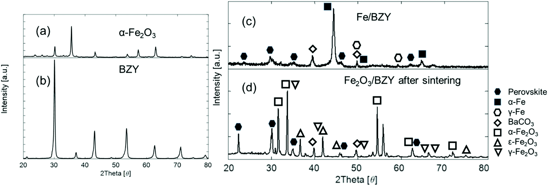
Fig. 2 shows the XRD patterns of the α-Fe2O3, BZY, and Fe2O3/BZY composites. Fig. 2(a) shows the XRD pattern of the as-obtained α-Fe2O3. In Fig. 2(b), all the peaks could be assigned to those of a typical perovskite structure, suggesting that BZY was successfully synthesised. According to Fig. 2(c), after the mixture of BZY powder and α-Fe2O3 was sintered at 1300 °C, some of the BZY was decomposed into carbonates and oxides, and the phase transition of α-Fe2O3 to ε-Fe2O3 and γ-Fe2O3 occurred simultaneously. The iron oxides were reduced to a metallic state, as shown in Fig. 2(d). In contrast, the perovskite structure in the composite remained stable after the reduction treatment.
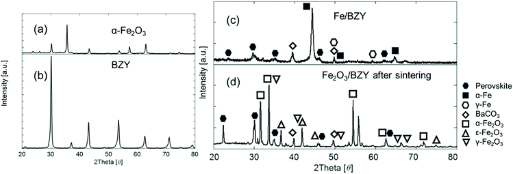 |
| | Fig. 2 XRD patterns of (a) as-obtained α-Fe2O3, (b) as-calcined BZY powders, (c) Fe2O3/BZY reduced at 500 °C for 1 h, and (d) as-synthesized Fe2O3/BZY at a weight ratio of 4:1 and calcined at 1300 °C for 12 h in air. | |
Fig. 3 shows the SEM-EDS cross-sectional images of the electrolysis cells containing the Fe2O3/BZY–RuO2 cathode catalyst. It is evident from Fig. 3(a) and (b) that the cathode catalyst layer reduced in size after the electrolysis reaction, which probably resulted from the reduction of RuO2. In addition, it is clear that the particle size of the cathode catalyst increased after electrolysis. The particle size increase is also supported by the EDS mapping images of the Ru species (Fig. 3(c) and (d)), which indicates that a slight aggregation of the Ru species occurred during the pre-reduction treatment and electrolysis reaction. The aggregation might have been caused by the reduction of RuO2 and the NRR on the active sites. Nevertheless, even after the electrolysis reaction, the Ru species were uniformly dispersed over Fe/BZY, as indicated in the magnified SEM-EDS image (Fig. 3(e)). There seems to be no clear interpenetration of the electrolyte material into the cathode catalyst layer after electrolysis because the distribution of P, Si, and Cs is confined to the electrolyte phase before and after the electrolysis test, as shown in Fig. 3(c) and (d). This implies that no reaction occurred between the acidic electrolyte material and cathode catalyst. In some fuel cells where caesium phosphate-based electrolytes are used, the electrolyte materials penetrate the electrode layers after current loading.23 This is because the wettability of the electrolyte materials towards the electrocatalyst materials is low, and accordingly the electrolyte materials are retained within the electrolyte layer.
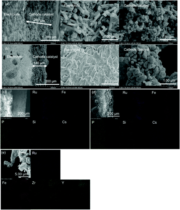 |
| | Fig. 3 Cross sectional SEM-EDS images of the electrolysis cells containing a cathode catalyst which consists of a mixture of 75 mg Fe/BZY and 75 mg RuO2: (a) as-prepared before H2 reduction, but prior to electrocatalytic tests, (b) after electrocatalytic tests, (c) as-prepared before H2 reduction, but prior to electrocatalytic tests, (d) after electrocatalytic tests, and (e) magnified image after electrocatalytic tests. | |
The reducibility of Fe/BZY and Fe/BZY–RuO2 was investigated by TPR (Fig. 4). In the TPR profile, a sharp peak appears at low temperatures and a broad peak appears at high temperatures. The low temperature peak exists only in the profile of the RuO2-containing catalysts, whereas the high temperature peak is observed in the Fe/BZY-containing catalysts. Accordingly, the low- and high-temperature peaks are attributed to the reduction of the RuO2 and iron oxide species, respectively. The low temperature peaks, indicated by ① and ② in the TPR profiles, correspond to the reduction of the RuO2 oxidised by the dilute O2/He gas at 220 °C. The reduction temperatures of RuO2 in Fig. 4 are lower than those shown in Fig. S1 (ESI†), which implies that fresh RuO2 is more easily reduced. The TPR profile of Fe/BZY shown in Fig. S1 (ESI†) indicates that the iron component in the prepared Fe/BZY was partially oxidised in ambient atmosphere. The high temperature peaks, indicated by ③ and ④ in the TPR profile, can most likely be assigned to the reduction of Fe2O3 to Fe3O4. The peaks indicated by ⑤ and ⑥ are derived from the reduction of Fe3O4 to Fe.24 Only in the TPR profile of Fe/BZY–RuO2 (red) in Fig. 4 is a new peak (⑦) observed at 186 °C. This peak could stem from the reduction of the fresh Fe2O3 formed on the surface of Fe in dilute O2/He gas at 220 °C. It follows that with the addition of RuO2 (the RuO2 is partially reduced by H2 generated at the cathode), the in situ oxidised Fe, which most likely forms by the steam present under the electrolysis conditions, could be reduced at 220 °C, and thus the activity of the Fe/BZY catalyst could be regained.
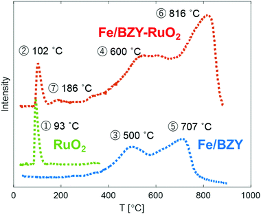 |
| | Fig. 4 TPR profiles of 5 mg RuO2 (green), 5 mg Fe/BZY (blue), 5 mg RuO2, and 5 mg of the Fe/BZY mixture (red) oxidized at 220 °C. | |
Blank experiments at OCV
An error in quantification might occur if NH3 from the ambient atmosphere adsorbs on the cell or NH3 is absorbed by the water trap. Accordingly, three kinds of blank experiments were conducted under open-circuit conditions. Blank experiments 1 and 2 were intended to exclude the possibility of ambient NH3 absorption in the water trap. Blank experiment 3 aimed to examine whether the gas leakage between the anode and cathode chambers could cause catalytic NH3 production in the H2 and N2 gas flows to the anode and cathode, respectively. The amount of trapped NH3 during the blank experiments, which included a collection time of 30 min, was below the detection limit (0.01 mg-N L−1, equivalent to 2.5 × 10⁻¹¹ mol (s cm2)−1). Therefore, both the ambient and catalytically generated NH3 could be ignored. Furthermore, N2H4 could not be detected in the blank experiments, which suggests that the colorimetric error due to other factors could be ignored (1 μg N2H4 L−1 is equivalent to 1.1 × 10⁻¹² mol (s cm2)−1) (Table S1, ESI†). Since the reagents used to synthesize the catalyst and electrolyte did not contain any N species, the origin of NH3 could be confirmed to be from the reaction of the feeding N2 gas flow.
Electrolysis results
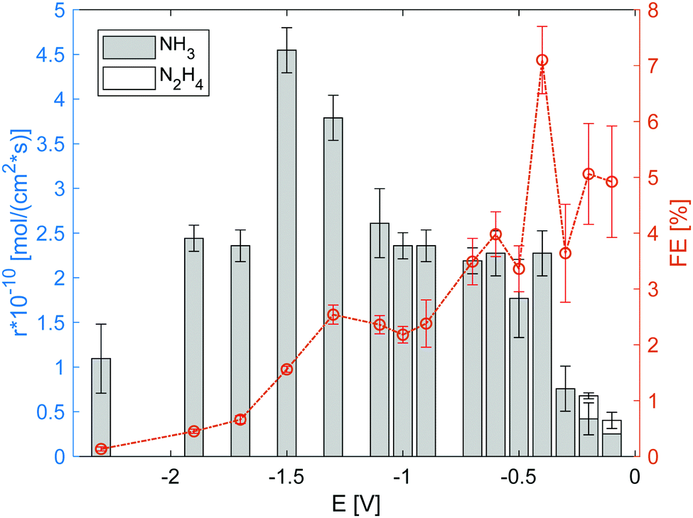
The electrolysis cell was polarized under the flow of dry N2 to the cathode and humidified H2 to the anode, and the effluent gas from the electrode chambers was passed through a water trap for gas collection and analysis. Fig. 5 summarises the gas analysis results for the voltages applied (vs. OCV). Both NH3 and N2H4 were detected in the applied voltage range from −0.1 V to −2.5 V. Because the products were only detected in the water trap of the cathode side, the cross leakage between the anode and cathode could be neglected. The detection of N2H4 suggests that N2 reduction proceeded via the association mechanism.7,25 Notably, the NH3 production rate when using only RuO2 (Fig. S6, ESI†) or Fe/BZY (Fig. S7, ESI†) as the cathode catalyst was approximately 1 × 10⁻¹⁰ mol (s cm2)−1; no N2H4 was detected. The nitrogen reduction rate over the RuO2 cathode reduced prior to electrolysis, at low applied voltages, was comparable to that over the Fe/BZY–RuO2 catalyst. Despite the similar nitrogen reduction rates at low applied voltages, no N2H4 was detected over the RuO2 catalyst, which supports the theory that the N–N bond dissociation in the intermediates is fast over precious metal catalysts during the associative mechanism.17 Another possibility is that the NRR proceeds via the dissociation mechanism when only the RuO2 catalyst is used. When the applied voltage was higher, the faradaic efficiency decreased to 0.5%, which indicates that the RuO2 electrode surface was mainly occupied by H2 species and H2 evolution was prominent. Over the Fe/BZY catalyst, a similar nitrogen reduction rate was attained, but the faradaic efficiency was quite low (less than 1%). As indicated by the TPR spectrum in Fig. 4, the Fe surface of the Fe/BZY electrode catalyst could be partially oxidised. Because iron oxides are rather inactive in the NRR,9 such partially oxidised Fe surfaces function as H2 generation sites, leading to a small faradaic efficiency over the Fe/BZY catalyst.
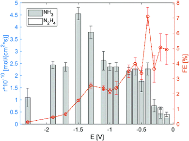 |
| | Fig. 5 Production rate and corresponding faradaic efficiency (FE) of NH3 and N2H4 under 3% humidified H2 anode atmosphere. The error bars are standard deviations. | |
Fig. 6 shows the impedance spectrum measured under dry N2 in the cathode and humidified H2 in the anode, as represented in the Nyquist plot. Fig. 7(a) shows the equivalent circuit model used to fit the impedance spectra. In the equivalent circuit, one ohmic resistance (Rs) and two parallel circuits of a constant phase element (CPE) and resistance (R1, R2) are included to express the electrode reaction processes, along with an inductor (L1). The inductance is attributed to the inductance of the cables used in the impedance measurement apparatus, and thus was invariant to measurement conditions (Table S3, ESI†). Fig. 7(b) summarizes Rs, R1, and R2 at different bias potentials. Rs is mainly attributable to the ohmic resistance of the electrolyte, whereas R1 and R2 are attributed to non-ohmic polarisation resistance. The ohmic resistance is constant irrespective of the applied voltage, and the non-ohmic polarisation resistance decreases from −0.1 V to −0.5 V. The characteristic frequency of the arc for R2 (f2 in Table S3, ESI†) is less than 10 Hz at the applied voltages, and consequently, the process characterized by the arc of R2 in the RC parallel circuit can be assigned to a slow process, such as gas diffusion in the electrode.26 In addition, the characteristic frequency of the high-frequency arc is in the order of kHz. Accordingly, it is feasible that the process characterized by the high-frequency arc of R1 is related to electrochemical reactions at the electrode surface and electrode/electrolyte interface. Notably, the smallest non-ohmic polarisation resistance at −0.4 V corresponds to the highest faradaic efficiency at −0.4 V, as shown in Fig. 5.
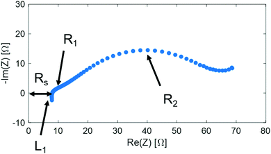 |
| | Fig. 6 Impedance under dry N2 cathode atmosphere and 3%-humidified H2 anode atmosphere. | |
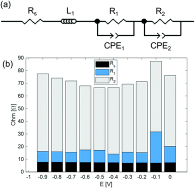 |
| | Fig. 7 (a) Simplified equivalent circuit model. (b) Rs, R1, and R2 parameters obtained from the equivalent circuit fitting results. | |
Model of potentiostatic pulse experiment
Fig. 8 illustrates the potential step program and current response during the potentiostatic pulse experiment. In this experiment, first, a constant current of iw is loaded at an applied voltage of Ew for the period tw. Consequently, the applied voltage is quickly converted stepwise to the OCV. Upon the quick return of the applied voltage to the OCV, the current starts to flow contrarily to iw and gradually ceases to 0. Here, the reverse current is denoted as iocv, and the period for iocv to reach 0 is tocv. In the following experiments, Ew was applied for the period tw = 400 s.
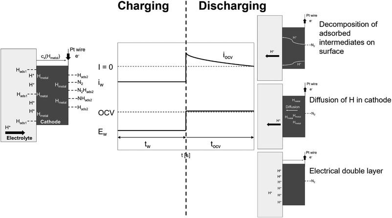 |
| | Fig. 8 Schematic diagram of potential step and current response during potentiostatic pulse experiment and general model profiles of charging (tw) and discharging (tocv) processes under dry N2. | |
The potentiostatic pulse experiments were conducted by feeding humidified H2 to the anode and dry N2 or dry Ar to the cathode. The former condition is similar to the electrolysis mode used for the synthesis of NH3; in the latter, the same gas atmosphere is used at the cathode side as in proton pumping. During the period tw, protons are transferred from the anode to cathode and electrons are received to form a H layer (Hads1) at the electrolyte/cathode interface. Subsequently, the adsorbed Hads1 atoms dissolve into the cathode, where they are in equilibrium with the Hmetal concentration just below the cathode/electrolyte interface (Hmetal denotes H atoms in the bulk metal of the cathode catalyst). This is followed by the diffusion and trapping of the Hmetal atoms in the bulk metal.27 The Hmetal atoms then cross the cathode to the cathode/gas interface and reach an equilibrium value (Hads2) on the cathode surface. When dry Ar feed is used in the cathode, only Hads2 is assumed to reside at the surface of the electrode catalyst during the period tw, while under a dry N2 feed, N2-containing species (N2Hads2 and/or NHads2) could adsorb on the electrode catalyst surface in addition to Hads2. In this model, iocv is derived from three types of reactions. The first reaction involves the decomposition and ionisation of adsorbed species on the surface of the cathode catalyst. When using a dry Ar feed, only the Hads2 → H+ + e− reaction needs to be considered as the reverse current source during tocv. When using a dry N2 feed, the decomposition reactions of the intermediates, such as N2Hads2 and/or NHads2, should also be considered. The second reaction stems from the remaining Hmetal in the bulk metal, while the third reaction is due to the electrical double layer.
The iocv from the remaining Hmetal in the bulk metal will be discussed first, based on the following analyses. According to Pound et al.,28,29 when the proton transfer across the cathode/electrolyte interface is very fast, the iocv from Hmetal → H+ + e− is only controlled by the diffusion of Hmetal. They adopted the following boundary conditions at the electrode surface as
where
x is the distance from the electrolyte/cathode interface,
t is the diffusion time and
c stands for the consentration,
26 because H
metal cannot diffuse to the electrode/gas boundary within a charge time of less than 20 seconds, which they applied to the analysis of their experimental results.
29 In this work, we adopted a long enough charging time of 400 seconds, and accordingly H
metal atoms are considered to diffuse to the cathode/gas interface to form the adsorbed hydrogen on the cathode surface, and are released as gaseous H
2 in a steady state. Therefore, the boundary conditions are different from those by Pound
et al., and with appropriate boundary conditions in our study it is feasible to take into account the contributions of the decomposition of the adsorbed species at the cathode surface and the electrical double layer at the cathode/electrolyte interface to the
iocv.
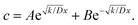
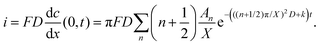
At the charging step, it can be assumed that the H atom traps are unsaturated, and therefore the trapping rate constant, k, remains constant. Fick's second law of diffusion can be modified with kc, where k is the trapping rate constant and c(x,t) is the concentration of Hmetal at a distance x from the electrolyte/cathode interface and at a time t, which starts from tw = 0. D is the diffusion coefficient of Hmetal in the cathode.
| |  | (1) |
| |  | (2) |
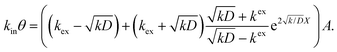
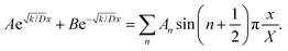
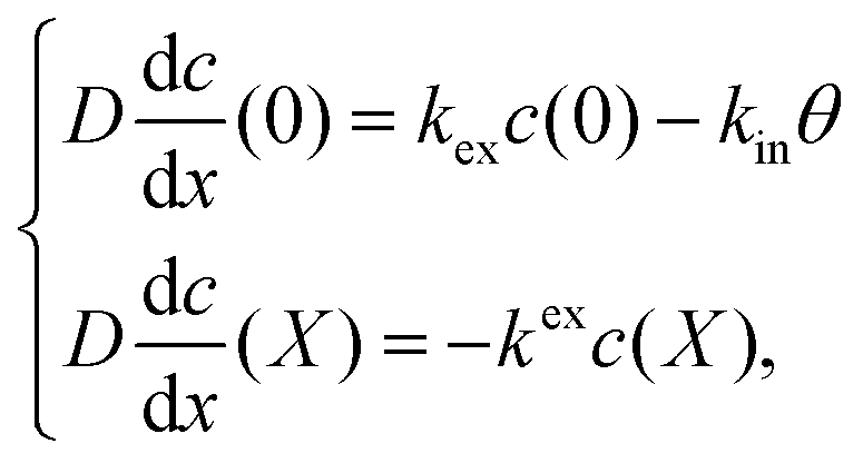
θ in
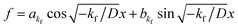
eqn (3) represents the adsorbed H on the electrolyte side at the interface of the cathode and electrolyte. The boundary conditions thus become:
| | 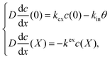 | (3) |
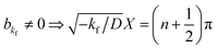
where
kex and
kin are the rate constants of H moving out of the cathode and the ingress of H into the cathode at the electrolyte/cathode interface, respectively.
X represents the thickness of the cathode catalyst, and has a value of 200 μm, as shown in
Fig. 3(a) and (b). By substituting
eqn (2) into
eqn (3), the following is obtained:
| |  | (4) |
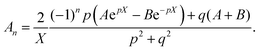
Thus, A and B can be obtained by eqn (5) and (6).
| |  | (5) |
| |  | (6) |
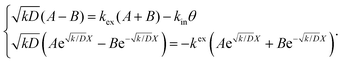
In the discharging step, taking into account the effect of the Hmetal atoms trapped in the bulk metal, Fick's second law of diffusion can be modified with kc; time t starts from tocv = 0.
| | 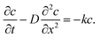 | (7) |
The boundary conditions thus become:
| |  | (8) |
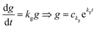
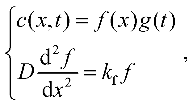
The following assumption is then made:
| | 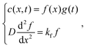 | (9) |
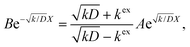
where, if
kf > 0, then
. By substituting the boundary conditions,
f = 0 can be obtained. If there is no H trapping, which implies
k = 0, then
f = 0. If
kf < 0, then
. By substituting the boundary conditions,
akf = 0 and
, where
n is an integer. Because
kg =
kf −
k < 0,
.
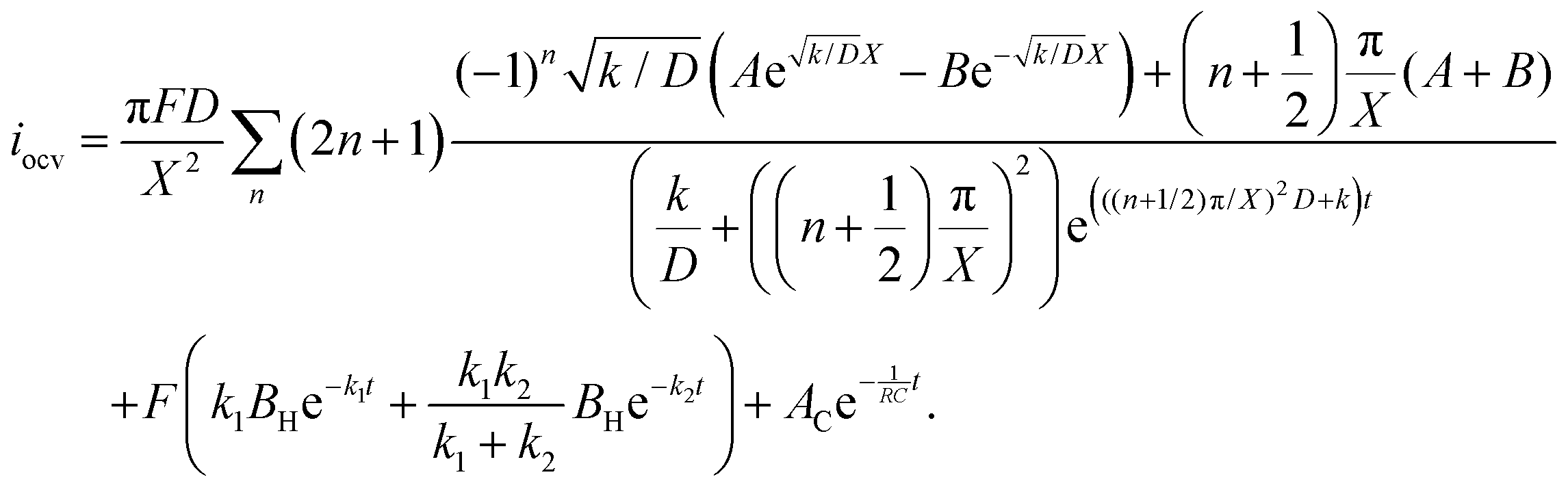
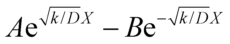
F is Faraday's constant. Thus, the following is obtained:
| |  | (10) |
| |  | (11) |
By substituting eqn (2) into eqn (10), the initial discharging condition is obtained as:
| |  | (12) |
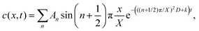
Taking integrals on both sides of eqn (12), we obtain eqn (13):
| |  | (13) |
Assuming  and
and  , we obtain eqn (14) and (15),
| |  | (14) |
| |  | (15) |
Thus, iocv derived from Hmetal is given as:
| | 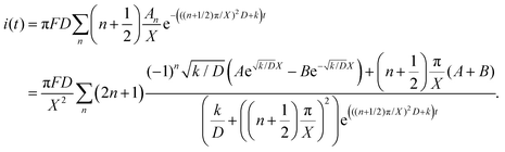 | (16) |
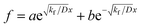
For the adsorbed species on the surface with dry Ar feed, only the Hads2 → H+ + e− reaction occurs on the surface of the cathode. Here, k1 represents the reaction rate constant of Hads2 → H+ + e−, and βH is the amount of adsorbed H atoms.
| |  | (17) |
When using a dry N2 feed, if the NRR is mainly in accordance with the associative mechanism, N2Hads2 → N2ads2 + Hads2 and Hads2 → H+ + e− are the reactions that occur on the surface of the cathode. Otherwise, NHads2 → Nads2 + Hads2 and Hads2 → H+ + e− reactions occur. Here, k2 represents the reaction rate constant of NH or N2H decomposition, and βNHorN2H is the amount of NH or N2H adsorbed.
| | 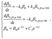 | (18) |
| | 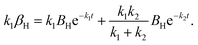 | (19) |
The third iocv reaction, which is due to discharge of the capacitor by the electrical double layer, is given as:
| |  | (20) |
Therefore, the total iocv in a dry Ar feed and dry N2 feed is given by:
| | 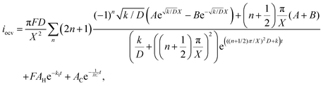 | (21) |
| | 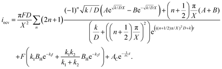 | (22) |
The raw iocv to tocv data, collected at −0.2 V, −0.5 V, −1.5 V, and −1.9 V, were fitted using eqn (21) with the D, k, k1, AH, (A + B), and 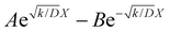 parameters. Based on our assumptions, the D and k parameters do not depend on the applied voltage E; however, k1, AH, A, and B does. Values for all the parameters were determined for each E, and it was verified that the values of D and k do not depend on E, where D is 1.0 × 10⁻⁹ m2 s−1 and k is 4.5 × 10⁻² s−1. With the D, k, AH, and k1 values obtained for the condition where a dry Ar gas atmosphere was used at the cathode side, the relationship between iocv and tocv under the same gas atmosphere under electrolysis conditions is provided by eqn (22). The raw iocv to tocv data, collected at −0.2 V, −0.5 V, −1.5 V, and −1.9 V, were fitted with the k2, (A + B),
 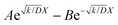 , C1, and C2 parameters. Fig. 9 shows the fitting results for the current response at the cathode side under a dry Ar gas atmosphere at the voltages applied (−0.2 V, −0.5 V, −1.5 V, and −1.9 V). In this figure, “surface” denotes the current response by the decomposition of intermediates on the surface of the catalyst, “diffusion” denotes the response by the diffusion of H in the catalyst, “capacitor” denotes the response by the electrical double layer, and “fitted” represents the summation of these three contributions. Fig. 10 summarises the fitting results at the cathode side under a dry N2 gas atmosphere at −0.2 V, −0.5 V, −1.5 V, and −1.9 V. The fitting results presented in Fig. 9 and 10 demonstrate that the developed model fits well with the experimentally measured current responses, and that the current responses assigned to the decomposition of the intermediates, diffusion of H atoms in the catalyst, and the electrical double layer are all positive and thus rational.
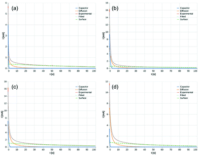 |
| | Fig. 9 Fitting results under dry Ar gas atmosphere at cathode side. (a) −0.2 V, (b) −0.5 V, (c) −1.5 V, and (d) −1.9 V. Surface: decomposition of intermediates on the surface of catalyst. Diffusion: diffusion of H in catalyst. Capacitor: electrical double layer. | |
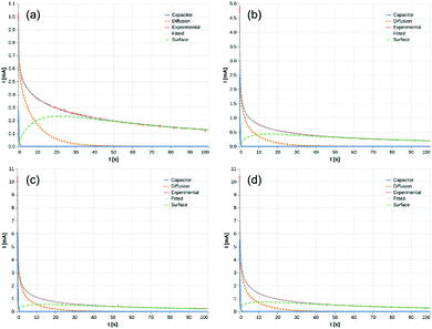 |
| | Fig. 10 Fitting results under dry N2 gas atmosphere at cathode side. (a) −0.2 V, (b) −0.5 V, (c) −1.5 V, and (d) −1.9 V. | |
Tables 1 and 2 summarise the parameters obtained from eqn (21) and (22). The common parameters, k and D, are equal to 0.045 s−1 and 1.0 × 10⁻⁹ m2 s−1, respectively. The value of k1 for all the applied voltages is approximately 0.012 s−1, which corresponds to the Hads2 → H+ + e− reaction. The values of k2 at −0.5, −1.5, and −1.9 V are similar, while k2 at −0.2 V is quite different. This suggests that the main adsorbed species are different depending on the applied voltages, and could explain why N2H4 was only detected at −0.2 V. From these results, it is inferred that at −0.2 V, the NRR proceeds mainly in accordance with the associative mechanism, while at higher voltages, the dissociative mechanism dominates. The value of k2 at −0.2 V is lower than that at −0.5, −1.5, and −1.9 V, which indicates that the energy barrier for the conversion of N2* to N2H* is lower than that for the conversion of N* to NH*. From Table 2, it is observed that the amounts of adsorbed NH* at −0.5, −1.5, and −1.9 V are similar, which could be equal to the total number of activation sites on the catalyst surface. The coverage of the activation sites by H atoms increased as the voltage increased; the high coverage could explain why the faradaic efficiency at −1.5 and −1.9 V is lower than that at −0.2 V and −0.5 V. The highest coverage ratio of NH* and the highest faradaic efficiency were achieved simultaneously at −0.4 V.
Table 1 Fitting results under dry Ar gas atmosphere at the cathode side
|
E [V] |
k
1 [10−2 s−1] |
β
H [10−7 mol] |
1/(RC) [s−1] |
| −0.2 |
1.0 |
3.9 |
3.9 |
| −0.5 |
1.1 |
5.4 |
1.5 |
| −1.5 |
1.2 |
9.2 |
1.8 |
| −1.9 |
1.6 |
5.4 |
3.7 |
Table 2 Fitting results under dry N2 gas atmosphere at the cathode side
|
E [V] |
k
1 [10−2 s−1] |
k
2 [10−1 s−1] |
β
H [10−7 mol] |
β
NHorN2H [10−7 mol] |
β
NHorN2H/(βNHorN2H + βH) |
1/(RC) [s−1] |
| −0.2 |
0.86 |
1.3 |
0.35 |
3.0 |
0.90 |
4.1 |
| −0.4 |
1.0 |
1.8 |
0.39 |
4.0 |
0.91 |
4.8 |
| −0.5 |
1.0 |
1.9 |
0.89 |
4.3 |
0.83 |
5.0 |
| −1.5 |
1.2 |
1.8 |
1.5 |
4.2 |
0.74 |
4.9 |
| −1.9 |
1.2 |
2.0 |
3.1 |
4.3 |
0.58 |
4.6 |
Conclusions
A novel Fe/BZY cathode catalyst was synthesised and applied with the addition of RuO2 to the electrochemical synthesis of NH3 using a proton-conducting electrolyte CsH2PO4/SiP2O7 at 220 °C and ambient pressure. With the addition of RuO2, the NH3 production rate increased and N2H4 was detected at −0.2 V; this might be because the oxidation of Fe was suppressed. The highest faradaic efficiency of 7.1% was achieved at −0.4 V (vs. OCV), which exhibited the highest NH3 yield rate of 4.5 × 10⁻¹⁰ mol (s cm2) at −1.5 V (vs. OCV). A by-product, N2H4, was detected at −0.2 V (vs. OCV). While the electrochemical NH3 production rate using only Fe/BZY or RuO2 was approximately 1.0 × 10⁻¹⁰ mol (s cm2)−1, which is comparable to the N2 reduction rate over Fe/BZY–RuO2, no N2H4 was detected. An equivalent circuit model was suggested to fit the impedance spectra. The fitting results were consistent with the highest faradaic efficiency achieved at −0.4 V. A model of the current response achieved by the potentiostatic pulse experiment was developed. The model comprised the decomposition of adsorbed intermediates on the surface of the cathode catalyst, diffusion of H in the cathode catalyst, and an electrical double layer. The current response was fitted to the model and the results showed that a high coverage ratio of NH* (and/or N2H*) was attained at the applied voltage at which a high faradaic efficiency was achieved, and the coverage of NH* (and/or N2H*) on mixed Fe/BZY–RuO2 was much higher than that on only Fe/BZY or RuO2 (Table 2 and Tables S4, S5, ESI†).
Conflicts of interest
The authors declare no conflicts of interest.
Acknowledgements
This work was supported by the Japan Society for the Promotion of Science (JSPS) KAKENHI grants 20H02521, Japan and Japan Science and Technology Agency (JST) CREST JPMJCR1441. Y. Y. was financially supported by the Graduate School of Engineering, The University of Tokyo Doctoral Student Special Incentives Program (SEUT). Y. Y. would like to thank Mr Naoya Fujiwara for his helpful comments and Mr Ryuichi Ohori for discussions regarding the model.
References
- A. Jafari, A. Ebadi and S. Sahebdelfar, React. Kinet., Mech. Catal., 2019, 126, 307–325 CrossRef CAS.
- C. X. Guo, J. R. Ran, A. Vasileff and S.-Z. Qiao, Energy Environ. Sci., 2018, 11, 45–56 RSC.
- Y. Bicer and I. Dincer, Int. J. Energy Res., 2017, 41, 1987–2000 CrossRef CAS.
- Y. Bicer and I. Dincer, J. Electrochem. Soc., 2017, 164, H5036–H5042 CrossRef CAS.
- S. Kishira, G. Qing, S. Suzu, R. Kikuchi, A. Takagaki and S. T. Oyama, Int. J. Hydrogen Energy, 2017, 42, 26843–26854 CrossRef CAS.
- B. Ma, H. Zhao, T. S. Li, Q. Liu, Y. Luo, C. Li, S. Lu, A. M. Asiri, D. Ma and X. Sun, Nano Res., 2020, 1–15 Search PubMed.
- C. J. M. van der Ham, M. T. M. Koper and D. G. H. Hetterscheid, Chem. Soc. Rev., 2014, 43, 5183–5191 RSC.
- Y. Abghoui, A. L. Garden, J. G. Howalt, T. Vegge and E. Skúlason, ACS Catal., 2016, 6, 635–646 CrossRef CAS.
- L. Hu, A. Khaniya, J. Wang, G. Chen, W. E. Kaden and X. Feng, ACS Catal., 2018, 8, 9312–9319 CrossRef CAS.
- S. Licht, B. Cui, B. Wang, F.-F. Li, J. Lau and S. Liu, Science, 2014, 345, 637–640 CrossRef CAS.
- M. Wang, S. Liu, T. Qian, J. Liu, J. Zhou, H. Ji, J. Xiong, J. Zhong and C. Yan, Nat. Commun., 2019, 10, 341 CrossRef CAS.
- X. Lv, F. Wang, J. Du, Q. Liu, Y. Luo, S. Lu, G. Chen, S. Gao, B. Zheng and X. Sun, Sustainable Energy Fuels, 2020, 4, 4469–4472 RSC.
- H. Yu, Z. Wang, D. Yang, X. Qian, Y. Xu, X. Li, H. Wang and L. Wang, J. Mater. Chem. A, 2019, 7, 12526–12531 RSC.
- D. Bao, Q. Zhang, F.-L. Meng, H.-X. Zhong, M.-M. Shi, Y. Zhang, J.-M. Yan, Q. Jiang and X.-B. Zhang, Adv. Mater., 2017, 29, 1604799 CrossRef.
- T. Matsui, T. Kukino, R. Kikuchi and K. Eguchi, J. Electrochem. Soc., 2006, 153, A1077 CrossRef.
- N. Lazouski, Z. J. Schiffer, K. Williams and K. Manthiram, Joule, 2019, 3, 1127–1139 CrossRef CAS.
- A. R. Singh, B. A. Rohr, M. J. Statt, J. A. Schwalbe, M. Cargnello and J. K. Nørskov, ACS Catal., 2019, 9, 8316–8324 CrossRef CAS.
- A. R. Singh, B. A. Rohr, J. A. Schwalbe, M. Cargnello, K. Chan, T. F. Jaramillo, I. Chorkendorff and J. K. Nørskov, ACS Catal., 2017, 7, 706–709 CrossRef CAS.
- Y. Yuan, R. Kikuchi, A. Takagaki and S. T. Oyama, ECS Trans., 2017, 78, 451–459 CrossRef CAS.
- T. P. Dirkse and N. A. Hampson, Electrochim. Acta, 1972, 17, 1113–1119 CrossRef CAS.
- P. Delahay, S. Oka and H. Matsuda, J. Am. Chem. Soc., 1960, 82, 329–332 CrossRef CAS.
- G. W. Watt and J. D. Chrisp, Anal. Chem., 1952, 24, 2006–2008 CrossRef CAS.
- G. Qing, K. Sukegawa, R. Kikuchi, A. Takagaki and S. T. Oyama, J. Appl. Electrochem., 2017, 47, 803–814 CrossRef CAS.
- G. Munteanu, L. Ilieva and D. Andreeva, Thermochim. Acta, 1997, 291, 171–177 CrossRef CAS.
- M. A. Shipman and M. D. Symes, Catal. Today, 2017, 286, 57–68 CrossRef CAS.
- C.-H. Li, S.-H. Hu, K.-W. Tay and Y.-P. Fu, Ceram. Int., 2012, 38, 1557–1562 CrossRef CAS.
- J.-Y. Lee and S. M. Lee, Surf. Coat. Technol., 1986, 28, 301–314 CrossRef CAS.
- R. McKibben, R. M. Sharp, D. A. Harrington, B. G. Pound and G. A. Wright, Acta Metall., 1987, 35, 253–262 CrossRef CAS.
- B. G. Pound, G. A. Wright and R. M. Sharp, Acta Metall., 1987, 35, 263–270 CrossRef CAS.
Footnote |
| † Electronic supplementary information (ESI) available. See DOI: 10.1039/d0ma00905a |
|
| This journal is © The Royal Society of Chemistry 2021 |
Click here to see how this site uses Cookies. View our privacy policy here. 
 Open Access Article
 This Open Access Article is licensed under a Creative Commons Attribution-Non Commercial 3.0 Unported Licence
 b and
Ryuji
Kikuchi
b and
Ryuji
Kikuchi


 . By substituting the boundary conditions, f = 0 can be obtained. If there is no H trapping, which implies k = 0, then f = 0. If kf < 0, then
  . By substituting the boundary conditions, akf = 0 and
  , where n is an integer. Because kg = kf − k < 0,
  . F is Faraday's constant. Thus, the following is obtained:


 and
and  , we obtain eqn (14) and (15),


 parameters. Based on our assumptions, the D and k parameters do not depend on the applied voltage E; however, k1, AH, A, and B does. Values for all the parameters were determined for each E, and it was verified that the values of D and k do not depend on E, where D is 1.0 × 10⁻⁹ m2 s−1 and k is 4.5 × 10⁻² s−1. With the D, k, AH, and k1 values obtained for the condition where a dry Ar gas atmosphere was used at the cathode side, the relationship between iocv and tocv under the same gas atmosphere under electrolysis conditions is provided by eqn (22). The raw iocv to tocv data, collected at −0.2 V, −0.5 V, −1.5 V, and −1.9 V, were fitted with the k2, (A + B),
  , C1, and C2 parameters. Fig. 9 shows the fitting results for the current response at the cathode side under a dry Ar gas atmosphere at the voltages applied (−0.2 V, −0.5 V, −1.5 V, and −1.9 V). In this figure, “surface” denotes the current response by the decomposition of intermediates on the surface of the catalyst, “diffusion” denotes the response by the diffusion of H in the catalyst, “capacitor” denotes the response by the electrical double layer, and “fitted” represents the summation of these three contributions. Fig. 10 summarises the fitting results at the cathode side under a dry N2 gas atmosphere at −0.2 V, −0.5 V, −1.5 V, and −1.9 V. The fitting results presented in Fig. 9 and 10 demonstrate that the developed model fits well with the experimentally measured current responses, and that the current responses assigned to the decomposition of the intermediates, diffusion of H atoms in the catalyst, and the electrical double layer are all positive and thus rational.
