
 Open Access Article
 This Open Access Article is licensed under a
 Creative Commons Attribution 3.0 Unported Licence
From chemical curiosity to versatile building blocks: unmasking the hidden potential of main-group phthalocyanines in organic field-effect transistors
Weiyi
Zhou
a,
Nathan J.
Yutronkie
 a,
Benoît H.
Lessard
bc and
Jaclyn L.
Brusso
*a
a,
Benoît H.
Lessard
bc and
Jaclyn L.
Brusso
*a
aDepartment of Chemistry and Biomolecular Sciences, University of Ottawa, 150 Louis Pasteur, Ottawa, ON K1N 6N5, Canada. E-mail: jbrusso@uottawa.ca
bDepartment of Chemical and Biological Engineering, University of Ottawa, 161 Louis Pasteur, Ottawa, ON K1N 6N5, Canada
cSchool of Electrical Engineering and Computer Science, University of Ottawa, 800 King Edward Ave. Ottawa, Ontario K1N 6N5, Canada
First published on 11th December 2020
Abstract
Over the past few decades, metal phthalocyanines (MPcs) have been thoroughly investigated as active materials in organic field effect transistors (OTFTs) towards the commercialisation of flexible integrated circuits and displays. One of several advantages to MPcs as building blocks for OTFTs is the high degree of functionality, from which the choice of metal ion, substituents along the phthalocyanine framework and axially bound ligands can synergistically tune the physical and self-assembly properties of the material. Recent interest has been directed to the introduction of main-group elements as the central ion of MPcs as an avenue to install both hole and electron transport properties and improve device performance. In this review, we focus on the development of main-group phthalocyanines and their performances in OTFTs. General preparation of main-group MPcs are discussed for complexes integrated into OTFTs and further presented with a summary of their device performance.
 Weiyi Zhou | Weiyi Zhou received her Bachelor's degree (2018) in applied chemistry at Shenyang University of Chemical Technology, China. She is a Master student since September 2019 under the supervision of Prof. Jaclyn L. Brusso and Prof. Benoit H. Lessard in the University of Ottawa. Her research focuses on the design and synthesis of silicon phthalocyanines for electronic applications. |
 Nathan J. Yutronkie | Nathan J. Yutronkie received his BSc degree in Biophamaceutical Science from the University of Ottawa in 2014, where he completed an honours project under the supervision of Prof. Jaclyn Brusso. He subsequently continued graduate studies under her direction and recently obtained his PhD in Chemistry (2020). His research interests lie in the design and development of functional materials. |
 Benoît H. Lessard | Benoît Lessard obtained his PhD (2012) from McGill University in Polymer synthesis and reaction engineering. He then completed an NSERC Banting Postdoctoral Fellowship at the University of Toronto studying crystal engineering and engineering organic photovoltaics and organic light emitting diodes. In 2015, Benoît joined the Department of Chemical & Biological Engineering at University of Ottawa as an Assistant Professor and Tier 2 Canada Research Chair, and was promoted to Associate Professor in May 2019. In 2020, he was cross appointed to the School of Electrical Engineering and Computer Science. Lessard's group focuses on the development of new materials and their integration into thin film electronic devices such as organic thin film transistors and sensors. |
 Jaclyn L. Brusso | Jaclyn Brusso obtained her PhD from the University of Waterloo under the direction of R. T. Oakley in 2006. Following an NSERC Postdoctoral Fellowship with D. Perepichka at McGill University and then with S. Holdcroft's group at Simon Fraser University, Jaclyn joined the University of Ottawa in 2010 as an Assistant Professor and was promoted to Associate Professor in 2016. Jaclyn's research program focuses on the design and development of novel organic/inorganic based optical, magnetic and electronic materials. |
1. Introduction
Since their discovery in the early 20th century,1–3 metal phthalocyanines (MPcs) have played a pivotal role in paving research efforts across many scientific disciplines. The extensive delocalization of π-electrons in the phthalocyanine framework affords the foundation for a molecular architecture in possession of impeccable stability and rich electronic behaviour.4–7 While MPcs were initially used as dyes and pigments due to their green-blue optical appearances,1 this class of molecules have since been exploited for widespread applications in catalysis,8 liquid crystals,9 fluorescent probes and photosensitisers,10 optoelectronic and redox-active materials,11–14 magnetic materials,15 sensors,16 nonlinear optics,17 and molecular electronics,18–22 to name a select few.Regarding molecular electronics, MPcs have gained tremendous traction towards the development of active materials in organic photovoltaics (OPVs),23–26 light-emitting diodes (OLEDs),27–30 and field-effect transistors (OFETs).31–34 Given the monumental role of FETs in modern-day devices, the implementation of MPcs as intrinsic organic semiconductors within these devices offers several advantages over their traditional inorganic counterparts. For one, synthetic procedures of MPcs are relatively facile, inexpensive, and ideal for mass-production at an industrial scale. These materials can also be processed with ease through conventional wet-based or vapour deposition methods on a range of compatible can be fabricated for flexible integrated circuits and displays. When juxtaposed to most organic molecules, the MPc building block itself is thermally and chemically robust in comparison, which reinforces the feasibility of their application in these molecular devices. Perhaps the greatest appeal of MPcs, especially for those aiming to enhance the performance of OTFTs, originates in the structural versatility of the molecule. Synthetic handles can be used to manipulate the properties of the material with control for the application at hand, thereby providing a means to rationally design MPc-based building blocks from a bottom-up approach.
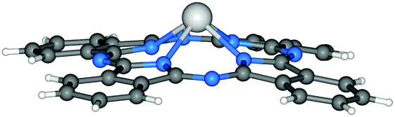
With that said, the molecular infrastructure of MPcs, comprised of four aza-bridged isoindoline subunits coordinated to a central metal inclusion, possesses four regions where the properties can be tailored accordingly by chemical modifications (Fig. 1).21 Functionalities can be enabled through the choice of the central ion (M), the substituents along the peripheral and bay positions (R1 and R2, respectively) of the phthalocyanine backbone (Pc), and the ligands bound at the axial positions of the metal centre (X).21 For sake of clarity and consistency, we herein refer to functionalised MPcs through the notation X1X2-M(R1mR2n)Pc, where 4-, 5- and 6-coordinate metal complexes are implied by the absence or inclusion of axial ligands X1 and X2, respectively. Furthermore, the degree and type of substitution along the Pc framework is denoted by R1m and R2n in parentheses, where m and n = 0–8.
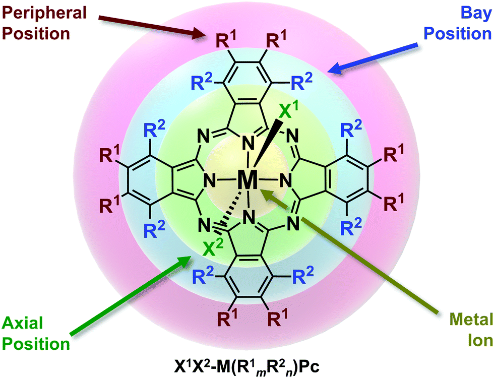 | ||
| Fig. 1 Chemical structure of metal phthalocyanines highlighting the regions for chemical functionalisation. Adapted with permission from ref. 21. Copyright 2015 American Chemical Society. | ||
To further elaborate on the influences imposed by functionalisation, solubility is a key property that can be controlled through chemical moieties appending from the Pc framework and/or central ion. In general, MPcs are not inherently soluble in most common solvents as a consequence of aggregation via non-covalent interactions. Nonetheless, the attachment of flexible chains can aid in the disruption of these interactions or, in the case of polar and ionic groups, can enhance interactions with solvent molecules. On the other hand, judicious choice of these substituents can be used to rationalise favourable interactions (e.g., π–π, C–H⋯X, where X = heteroatoms, π, etc.) towards the preferential alignment and self-assembly of molecules in a condensed state.35–37 Moreover, these same interactions can ultimately be used to strengthen intermolecular interactions in order to enhance the charge-transport properties.38
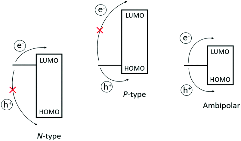
Functionalisation can also alter the electronic structure of MPcs (e.g., influence the highest occupied and lowest unoccupied molecular orbitals; HOMO and LUMO, respectively), which are derived from the extensive π-system of phthalocyanine. Considering metal-free Pcs, large coefficients of both the HOMO and LUMO reside on the phenyl α-carbon atoms (i.e., bay positions) and chelating nitrogen atoms, respectively.6,39,40 Hence, the orbital energies can be tailored by the direct implementation of electron-donating groups to destabilise MOs and electron-withdrawing groups which favour stabilisation.41,42 With the appropriate choice of substituents and central ion attached to the Pc framework, the energy levels can be synergistically perturbed with respect to the working electrode to afford unipolar n-type (charge carriers), p-type (hole carriers), or ambipolar (both) semiconductive materials, intrinsically. As for axial substituents, which are not directly attached to the Pc framework, electronic effects imparted by these groups are minimal in comparison. To date, MPcs studied in OTFTs have, in general, fallen into the category of p-type semiconductive materials, while reports of those leaning towards n-type are much scarcer.31 Presumably, this may reflect the large collection of easily accessible divalent transition metal complexes, which intrinsically favour p-type behaviour. Additionally, the lack of precursors available to construct electron-deficient Pc macrocycles capable of stabilising the LUMO energy levels for the injection of electrons may contribute to their slower progression.
Very recently, researchers have recognized an untapped potential in MPcs with the introduction of main-group elements as the central atom.38 By shifting away from transition metals, the higher oxidation states of the p-block elements, coupled with their electronegativity, have shown to afford stable unsubstituted MPcs that can behave intrinsically as n-type, and even ambipolar, in nature. Furthermore, the greater valencies for these ions provides an avenue to systematically assess the structure–property relationships through the presence of axial ligands, where most divalent MPcs are limited to substitutions along the Pc framework. Thus, the nature of organic semiconductors and the performance of devices can be optimised through these tuneable modes of functionalisation found within main-group Pcs. Although this class of MPcs show great promise, these materials on their own have several challenges in comparison to transition metal derivatives; the most obvious pertaining to the change in reactivity, which can impede synthetic preparations. Nonetheless, results are encouraging with the recent advances in synthetic methodologies for the preparation of main-group MPcs. By maximizing the utility of all synthetic handles to the fullest extent, it is merely a matter of time until these molecules showcase their true potential as versatile and high-performing building blocks in OTFTs.
To that end, the review herein aims to provide readers with a comprehensive overview of main-group phthalocyanines as prospective materials in OTFTs. Previous reviews on the subject of MPcs in OTFTs have primarily focused on the performances of transition metal complexes,43,44 while our focus is gravitated towards the preparative methods for this emerging class of MPcs and examine how functionalisation influences device performance. As the synthesis and reactivity for some MPcs have been covered in previous reviews,45–47 we will provide a brief outlook for these derivatives throughout the following section. Additionally, the synthesis of thallium and group 15 phthalocyanines have been excluded as the scope of this review pertains only to those complexes that have been implemented into OTFT devices.
2. Synthesis of main-group phthalocyanines
2.1 General synthesis of metal phthalocyanines
Highlighting the ubiquity of MPcs, over 95 metals and metalloids of the periodic table have been chelated to the indole nitrogen atoms of phthalocyanine.48 Of all these examples, two general preparative routes are typically employed as outlined in Scheme 1.39,46,49 The most common synthetic approach involves the template method, which entails the cyclotetramerisation of phthalonitrile (1a) guided by a metal/metalloid precursor. While halide salts (MXn where X = Cl, Br, I) are most prevalently used as the template, the use of elemental metals or alloys, which are subsequently reduced in the process, have also been reported. These reactions are often carried out at elevated temperatures in non-aqueous high boiling solvents (e.g., nitrobenzene, quinoline, chlorinated benzenes and naphthalenes) and, depending on the nature of the reagents, several conditions can be altered to optimise MPc formation. For example, metal centres possessing strong Lewis acidity can activate the external nitrile groups, enabling nucleophilic addition of disassociated halide ions and anionic intermediates during the initiation and propagation steps of the macrocyclisation. Additives such as bases (e.g., 1,8-diazabicyclo(5.4.0)undec-7-ene, DBU) and initiators (e.g., alkoxides) have also been shown to be effective at promoting ring formation. In addition to phthalonitrile, other 1,2-disubstituted benzenes have been employed as synthons for the template method, including 1,3-diiminoisoindolines (DIII; 1b), phthalamides (1c), phthalimides (1d), phthalic acids (1e), and phthalic anhydrides (1f). Depending on the reagents chosen, additional sources of nitrogen may also be required for phthalocyanine formation such as urea in the presence of a catalyst (e.g., (NH4)2MoO4). While the template method is by far the most employed preparative route for MPcs, direct metalation is also commonplace. The latter involves incorporation of the central ion following macrocycle formation, typically involving the reaction between a metal/metalloid halide salt and metal-free phthalocyanine.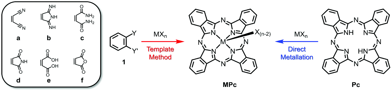 | ||
| Scheme 1 General synthesis towards MPcs using phthalonitrile and related synthons (1a–f) via the template method (red) or direct metallation of metal-free Pcs (blue). | ||
In view of tailoring the properties of MPcs, functionalisation at the peripheral, bay and axial positions has been extensively explored.44 To that end, functionalisation can occur post MPc synthesis or via incorporation of functional groups to precursors prior to macrocycle formation.39,46,49 The latter is most common for targeting the bay and peripheral positions, whereas the former is most appealing for axial substitution. For modifications about the Pc framework, the generation of MPcs with symmetrically substituted phthalonitriles or related precursors (e.g., 1a–f) is preferred as predictable substitution patterns, specifically with D4h symmetry, can be achieved rather than tediously modifying up to 16 positions post-cyclisation.49 Axial functionalisation on the other hand is best achieved through nucleophilic substitutions of an axial leaving group, such as chlorine and bromine atoms, bound to the central atom of preformed MPcs; however, the valency of the central ion must be considered as neutral divalent complexes are not generally capable of such functionalisation, whereas trivalent and tetravalent atoms offer one and two substituents, respectively.
As highlighted here, there are two main synthetic routes to generate MPcs, the template method and direct metalation. In moving towards main-group phthalocyanines, their preparation takes inspiration from this but some changes are necessary due to differences related to their reactivity, Lewis acidity, etc. This section will outline the synthesis and functionalisation of main-group Pcs for groups 13 and 14 elements and provide an overview of examples that sheds light towards their advancement as novel building blocks in OTFTs and related optoelectronic applications.
2.2 Group 13 phthalocyanines
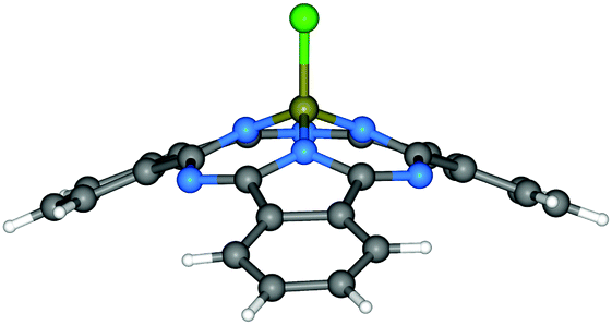 | ||
| Fig. 2 Molecular structure of Cl-BSubPc.57 Reproduced using reported cif. | ||
Since the synthesis, reactivity and reaction mechanism of a series of X-BSubPc derivatives have been well described in other review articles,58,59 herein we only briefly present some key aspects of their preparation. First synthesised serendipitously by Meller and Ossko in 1972,60 Cl-BSubPc was prepared via the reaction of phthalonitrile with gaseous boron trichloride (BCl3) in chloronaphthalene at 200 °C, which afforded a cyclotrimerised product with an axially bound chlorine atom in 40% yield (Scheme 2). Since then, the reaction has been modified over the years to address issues with yield, purity and practicality, as it is the most common approach to generate X-BSubPcs. For example, Giribabu et al. utilised microwave irradiation for this cyclisation, increasing the yield of Cl-BSubPc up to 90% and reducing the reaction time to only 4–6 minutes.61 Torres and co-workers described a highly efficient method for the synthesis of Cl-BSubPcs, refluxing a 1 M BCl3 solution in p-xylene with phthalonitrile, resulting in a yield of 82%.62 Through this approach, the boron reagent can be easily handled in solution oppose to gas, which allows for greater control over its stoichiometry and thus minimizing unwanted reactivity from excess Lewis acid. Additionally, the generation Cl2 as a side product is less pronounced through this method and significantly reduces the potential for halogenation along SubPc.
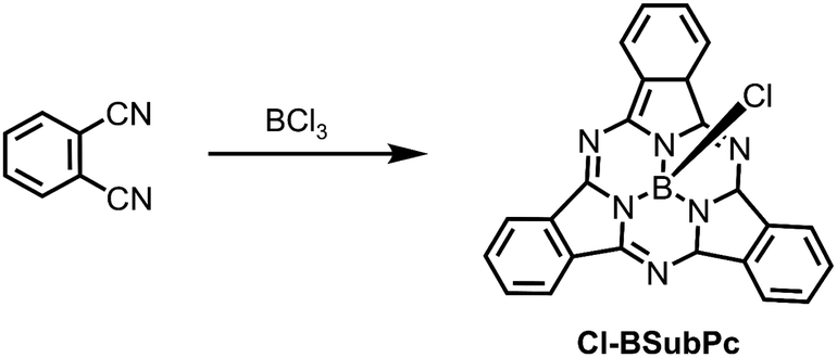 | ||
| Scheme 2 Cyclotrimerisation of phthalonitrile with BCl3 affording Cl-BSubPc. | ||
The cyclotrimerisation reaction has been adapted for the derivatisation of X-BSubPcs using pre-functionalised phthalonitriles. Meticulous attention must be given to the compatibility of the functional groups with the boron Lewis acid. Substituents such as alkanes, halogens, nitrates, thioethers and sulfones are typically unaffected in the synthesis, whereas limitations are seen with alcohols, amines, ethers, carbonyls and related unsaturated functional groups among others, due to their proclivity to react with acidic substrates. As such, these functionalities are best introduced with protecting groups or post-cyclisation.59 Recently, modifications to the π-conjugated framework of phthalonitrile has provided an alternative avenue to optimise the optoelectronic properties of X-BSubPcs. For instance, the frontier MOs can be stabilized from the replacement of the benzo moiety for electron-deficient heterocycles, such as pyrazine,63 thiophene,64 and 1,2,5-chalcadiazoles.65–67 On the other hand, when aromatic hydrocarbons68–70 and heterocycles71–75 are instead annulated to benzene, or even used to bridge other porphyrinoids,76–79 the extension of π-conjugation leads to bathochromic shifts in the main absorption band (Q-band).
Although less common, the boron reagent can be modified in these reactions in order to install non-halogen groups to the axial positions of X-BSubPc. For instance, treatment of phthalonitriles with BPh3 in the presence of base has led to both substituted and unsubstituted Ph-BSubPcs.80–82 An advantage to utilizing boron precursors with carbon-based groups is the tuning of the Lewis acidity (e.g., BPhnCl(3−n); n = 1–3), which subsequently suppresses undesirable reactivity with sensitive functionalities.66,83 As a trade-off, the stronger B–C bonds noticeably hinders product yields, due to the difficulties with eliminating the excess groups attached to the boron atom. In one instance, DIIIs were used as an alternative to phthalonitrile for these reactions. Regarding Ph-B(t-Bu)3SubPc, reaction of BPh3 with the either the corresponding DIII or phthalonitrile led to small differences in their yields (i.e., 3% and 5%, respectively). While the use of this precursor did not prove to be advantageous in the synthesis, DIII has found tremendous success in the preparation of silicon phthalocyanines, which will be discussed in detail in the following section.
Due to the lability of the B–Cl bond, various axially substituted BSubPcs can be easily prepared by displacing the halide with different nucleophiles. Such functionalisation thereby introduces an additional molecular fragment, which can be used to enhance structure–property relationships. For example, the substitution of the axial halide by a hydroxide group can be achieved by refluxing a suspension of X-BSubPc (X = Cl or Br) in water,84 or toluene/SiO2.85 Torres’ group devised an optimised method to synthesise phenol derivatives from Cl-BSubPcs by heating the appropriate phenols in toluene.62,86 In their following research, fullerene (C60) was introduced in the axial position of BSubPcs by 1,3 dipolar cycloaddition reaction between formyl-substituted BSubPcs and C60 in the presence of N-methylglycine.86 Besides water and phenol,85 other nucleophiles such as carboxylic acids,87 alkyl alcohols,68,88,89 and even some cholesterols89 can also yield corresponding axial-substituted derivatives. A ferrocene-based derivative, FcCO2-BSubPc, was obtained by refluxing a mixture of ferrocene carboxylic acid and Cl-BSubPc in o-dichlorobenzene (o-DCB), resulting in new donor–acceptor dyads that are potentially useful in light-harvesting elements.87 In order to synthesise trialkylsiloxy derivatives (R3SiO)-BSubPcs (R = alkyl), Zyskowski and Kennedy first heated a mixture of sodium metal and trihexylsilanol in anhydrous chlorobenzene to form the sodium salt, then added Cl-BSubPc and subsequently refluxed the reaction mixture for 1.5 hours.68 Alternatively, (R3SiO)-BSubPcs can also be obtained through a two-step reaction, first preparing the HO-BSubPc, then functionalizing it with trihexylchlorosilane via nucleophilic substitution, as reported by Martínez-Díaz et al.84 In 2011, Bender and co-workers discovered that phthalimides can also function as suitable nucleophiles in the displacement of the chloride in Cl-BSubPc to form phthalimido-boron subphthalocyanines.90 Interestingly, ∼10% of μ-oxo-(BSubPc)2 was also obtained as a by-product suggesting hydrolysation of Cl-BSubPc to HO-BSubPc occurs in the presence of trace amounts of water, which subsequently reacts with another equivalent of Cl-BSubPc or condenses with another HO-BSubPc.90
 | ||
| Fig. 3 Molecular structure of Cl-AlPc.95 Reproduced using reported cif. | ||
Additionally, DBU has been has shown to be effective at catalyzing the cyclotetramerisation of phthalonitrile in solution.96–102 As a result, a range of peripherally-functionalised Cl-MPc derivatives have been obtained that bear, for example, alkyl,99,101 thioethers,96 phenoxy,98,103 and pyridyloxy.104 Extended π-conjugated naphthalocyanines of each trivalent metal ion (MNcs) have also been reported using similar preparative methods as their X-MPc counterparts. More specifically, the synthesis of X-InNcs usually starts from the appropriate naphthalonitriles or DIIIs, which can be prepared from o-xylenes as reported previously.101,102,105 It has been demonstrated that the use of DIII affords a preformed naphthalocyanine core, which are much more reactive than the corresponding dicyanonaphthalenes.105 Apart from that, HO-AlPc106,107 and HO-GaPc100 derivatives can be directly synthesised based on dicarboxylic acid or dianhydride, with the presence of urea and catalyzed by ammonium molybdate.
Axial replacement of Cl-MPc (M = Al, Ga, In) can be facilitated by nucleophilic addition. Hydroxy derivatives are commonly obtained by hydrolyzing the corresponding Cl-MPc under acidic or basic conditions. For instance, HO-AlPc can be synthesised from the reaction of Cl-AlPc in the presence of NH4OH in a refluxing pyridine solution.108 HO-GaPc can be prepared by casting a concentrated sulfuric acid solution of Cl-GaPc into water followed by neutralisation with NH4OH.109 Based on the hydroxy derivatives, more axial substituted complexes can be prepared. For example, the conversion of HO-AlPc to F-AlPc can be achieved by treating the former with hydrofluoric acid (∼48 wt%).108,110,111 Similar conversion was achieved in the case of Cl-GaPc.110 In addition, Grant et al. reported a more straightforward and safer one-step synthetic route to obtain F-MPc from Cl-MPc (M = Al, Ga) directly, using cesium fluoride as the fluoride source in high boiling polar solvents.112 Phenol complexes are also commonly used nucleophiles that can introduce phenoxy groups onto the centre of MPcs, such as p-methoxyphenol,113 pentafluoro phenol,114p-nitrophenol,114p-chlorophenol,99etc. The introduction of aryl groups to the axial position of Pcs can be achieved by using appropriate Grignard reagents,99,101,103 or lithium salts for the introduction of aryl substituents101 upon nucleophilic substitutions of Cl-MPcs. Chen et al.115 even introduced InPcs into a polymer backbone by reacting Cl-InPc with polystyrene(MgBr)n. Apart from that, Sakai et al.116 synthesised poly(hydroxyimide)-AlPcs copolymer by the reaction of poly(hydroxyimide) with aluminium phthalocyanine triflate, which was obtained from Cl-AlPc and silver triflate. MPcs were also demonstrated to play an important role in the field of graphite materials, in which the first soluble graphite oxide (GO) axially substituted GaPc hybrid material was prepared by Li et al.117 in 2011. This was achieved via the reaction of Cl-GaPc with GO in DMSO at 110 °C in the presence of K2CO3.
2.3 Group 14 phthalocyanines
 | ||
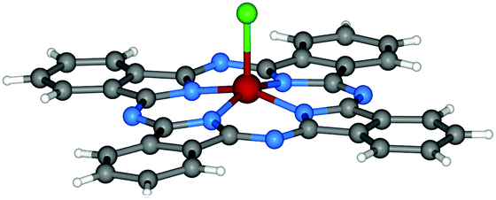
| Fig. 4 Molecular structure of Cl2-SiPc.118 Reproduced using reported cif. | ||
The first attempts to generate silicon phthalocyanines were focused on the direct metalation of Pc by Linstead.119 Although unsuccessful, these involved pressure tube reactions comprised of disodium phthalocyanine and silicon tetrachloride (SiCl4).119 Several decades later, Joyner and co-workers described the formation of what they proposed to be dichlorosilicon phthalocyanine (Cl2-SiPc) via the template method in 1960,120 which was later supported by elemental analysis.121 While reacting phthalonitrile with silicon SiCl4 in refluxing quinoline affords Cl2-SiPc, only 7% of the desired product was isolated using this approach. In the same report, various silicon sources were explored including trichloromethylsilane, trichloromethylsilane, and hexachlorodisiloxane to varying levels of success. Product formation was not observed for the former two reagents; however, the synthetic route employing hexachlorodisiloxane provided a yield of approximately 43%. Alternatives to phthalonitrile were reviewed in a study by Kenney in 1964, which demonstrated that both o-cyanobenzamide and DIII could be converted to Cl2-SiPc in 35% and 71% yields, respectively.122 The yield of this reaction has been enhanced by Marks and co-workers through their modified procedure that introduces DIII once the reaction temperature reached 200 °C, which afforded yields reaching 80%.123 Additionally, Noboru et al. synthesised Cl2-SiPc in a 90% yield by replacing quinoline with tetrahydronapthalene and tri-n-butylamine,124 yet the authors note that the crude product contains as much as 30–50% impurities.
The vast majority of derivatisation with respect to silicon phthalocyanines is directed to axial functionalisation (vide infra), while peripherally substituted complexes are few and far between. This may be attributed to the lack of commercially available DIIIs, along with their less than ideal preparative routes, which require the use of sodium metal and a constant flow of ammonia gas in a refluxing methanolic solution of phthalonitrile for several hours.122 However, an alternative approach to the classical preparative route for DIII was recently reported by Brusso and co-workers (Scheme 3) that employs LiN(TMS)2·Et2O as a nucleophilic source of nitrogen.125 This new route eliminates the undesired expenses attributed to the strenuous reaction conditions required and the hazardous reagents employed in the preparation of DIII, thus it is anticipated that other derivatives with modified molecular frameworks can now be explored.
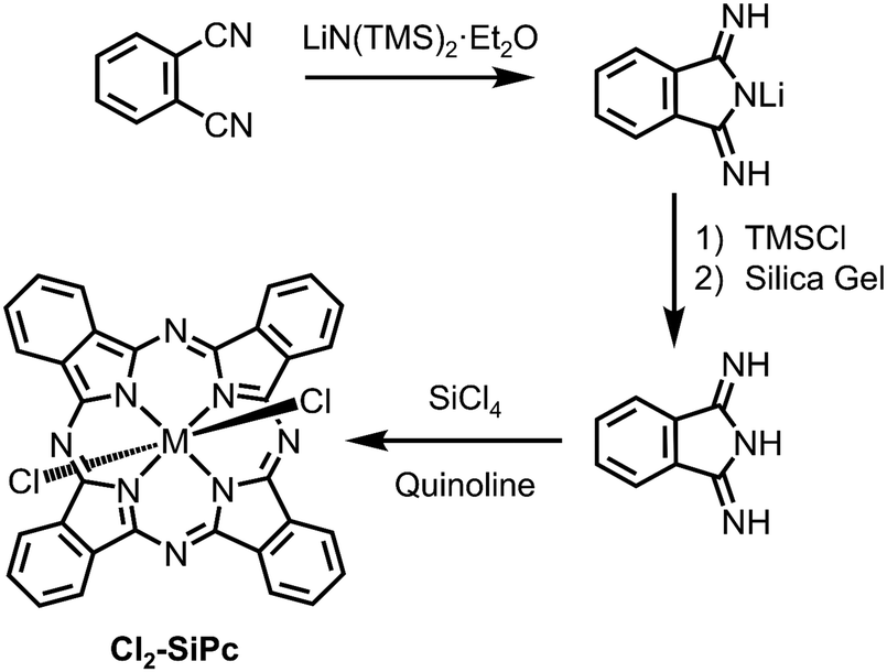 | ||
| Scheme 3 Synthetic routes in the preparation of Cl2-SiPc, including the preparation of DIII.125 | ||
In contrast to X2-SiPcs, tetravalent germanium complexes are readily prepared by the template reaction of phthalonitrile and germanium tetrachloride (GeCl4) to afford dichlorogermanium phthalocyanine (Cl2-GePc).123,126 Alternatively, Cl2-GePc can also be prepared by mixing powdered germanium metal with phthalonitrile under a stream of ICl vapor at ∼160 °C. The latter route affords isomorphous triclinic crystals of Cl2-GePc, whereas monoclinic crystals of Cl2-GePc can be prepared via the same reaction at ∼180 °C.127 At these temperatures, melted phthalonitrile undergoes catalytic tetramerisation while two-electron transfer occurs from the Ge atom to the Pc ring simultaneously and two other electrons are transferred from the Ge atom to ICl forming I− and Cl− ions.127 In 2017, Slodek et al. reported a less common synthetic route for Cl2-GePc in which the product was obtained by reacting 4-nitrophthalic anhydride with GeCl4 using urea as a source of ammonia and ammonium molybdate as the catalyst.128
In 1970, Joyner and co-workers129 reduced Cl2-GePc with sodium borohydride (NaBH4) or tin dichloride (SnCl2) to obtain divalent germanium phthalocyanine (GePc), which is a very light-sensitive compound. The authors also noted that a large excess of NaBH4 led to complete decomposition of the ring system. Interestingly, GePc is surprisingly resistant to oxidation back to form X2-GePc, while a similar oxidation process is much easier for divalent SnPc (vide infra).119 In the case of GePc, phthalocyanine oxidation and decomposition usually occur before the oxidation of GeII to GeIV, potentially due to the smaller covalent radius of GeII (compared to SnII), which could allow it to fit tightly within the Pc plane thereby enhancing its stability.45
The synthesis of dihydroxysilicon phthtalocyanine ((HO)2-SiPc) and dihydroxygermanium phthalocyanine ((HO)2-GePc)123,126 have been extensively reported with the most common preparative method achieved via hydrolysis of their dichloride counterparts. In these processes, both strongly acidic (typically involving concentrated sulfuric acid)121 and basic (employing, for example, sodium hydroxide,123,130 cesium hydroxide,131 concentrated aqueous ammonia,121 sodium methoxide,122etc.) conditions can be used to hydrolyze the Cl2-MPc complexes. In the case of (HO)2-SiPc, it can also be prepared directly from DIII. As well, the two axial positions of the tetravalent metal centres can be displaced by various substituents such as phenyl,132 phenoxy,25,126,128,131 siloxy,121,126,131,133 alkynyl,134 diethylaminophenoxyethoxy,135 1-benzylpiperidin-4-oxy,136 and even graphene137 or benzyl ester dendrimers.138 For this reason, a number of symmetrically and asymmetrically substituted X2-SiPc and X2-GePc derivatives have been developed over the years. The majority of axially substituted systems can be prepared via nucleophilic substitution of Cl2-MPc25,128,132,136,138 or (HO)2-MPc,120,121,126,131 while there are also examples starting from DIII for silicon-based derivatives. For example, Barker et al.132 first synthesised chloro phenyl silicon phthalocyanine chloride ((Cl)(Ph)-SiPc) by the reaction between DIII and phenyltrichlorosilane. They then synthesised a series of axial-substituted esters and bis-ether through nucleophilic displacement of one or two Cl substituents from either (Cl)(Ph)-SiPcCl or Cl2-SiPc, respectively.132 The introduction of various substituents can not only enhance the solubility of MPcs, but also suppress aggregation by introducing steric hindrance.139,140
Divalent tin phthalocyanine (SnPc) can be obtained by mixing metallic tin and phthalonitrile and heating to 300 °C without solvent.119 In addition, SnPc can also be prepared by the reduction of its tetravalent counterpart (e.g., Cl2-SnPc). For instance, Kroenke and Kenney142 reduced Cl2-SnPc with anhydrous SnCl2 in refluxing quinoline.142 Linstead and co-workers119 passed hydrogen through a solution of Cl2-SnPc in boiling quinoline to obtain SnPc. They also showed oxidation of solid SnPc with dry chlorine gas afforded the tetravalent dichlorotin chlorophthalocyanines, where chlorination was observed along the phthalocyanine framework. All the records suggest that interchange between stannous and stannic phthalocyanines can be readily affected (Scheme 4).
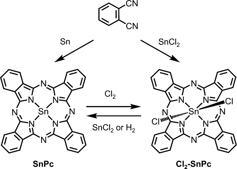 | ||
| Scheme 4 Synthetic routes to divalent SnPc and tetravalent Cl2-SnPc. | ||
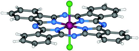
It is noteworthy that lead phthalocyanine (PbPc) is kind of abnormal compared with other phthalocyanines in which the central elements belong to group 14. Since the central Pb ion only exhibits bivalency, axial substituents cannot be attached to the central atom, thereby limiting functionalisation (Fig. 5). In general, PbPcs can be prepared by the violently exothermic reaction between litharge (PbO) and phthalonitrile,119,146 or by the more common reaction between phthalonitrile and PbCl2.143 Moreover, extended PbNcs have been achieved through similar reactions by treating 2,3-naphthalenedicarbonitrile with PbCl2.147
 | ||
| Fig. 5 Molecular structure of PbPc.148 Reproduced using reported cif. | ||
So far, the literature of axially substituted X2-SnPcs is notwell established, especially compared to X2-SiPcs. Similar to (HO)2-SiPc and (HO)2-GePc, (HO)2-SnPc123,142 can also be prepared via the hydrolysis of Cl2-SnPc in the presence of strong acid or base. Axial substituted reactions for SnPcs149 have been achieved via nucleophilic substitution of either (HO)2-SnPc or X2-SnPc. For example, Rafaeloff et al.150 prepared (Ph3CO)2-SnPc and (Ph3SiO)2-SnPc by reacting I2-SnPc or (HO)2-SnPc with triphenylcarbinol or triphenyisilanol, respectively. Then in 2002 Maree et al. synthesised diestronetin phthalocyanine by modifying their method used for substitution with silanols.149 In 2019, Lessard and co-workers reported the synthesis of two soluble axially functionalised tin phthalocyanines with silyl ethers, ((n-Bu)3SiO)2-SiPc and ((n-Hx)3SiO)2-SiPc (Bu = butyl; Hx = hexyl), by the reaction between Cl2-SnPc and corresponding tri-n-alkylchlorosilanes in the presence of NaOH and Aliquat HTA-1, a phase transfer catalyst, in boiling chlorobenzene.151 In early 2020, Lessard's group extended their research to the synthesis and the OTFT application of complexes with electron-deficient polyfluorinated aryl substituents at the axial positions, including (F5Ph)2-SnPc and (2,4,6-F3Ph)2-SnPc.34 The reaction of Cl2-SnPc with fluorophenol in refluxing chlorobenzene resulted in bis(fluorophenoxy) substituted SnPcs in good yields of ∼80%.
2.4 Group 15 and 16 phthalocyanines
Synthesis of group 15 MPcs dates back to Linstead's investigations in 1938,91 and since then, trivalent or pentavalent complexes of arsenic, antimony and bismuth have been synthesised.45 Despite this, the fabrication of OTFTs utilizing these systems as organic semiconductors has not been explored, and as the scope of this review encompasses the development of OTFTs with main-group phthalocyanines, we direct the reader to a previous review.45 However, it should be mentioned that, in addition to the metals and metalloids within this group, phosphorus represents the only non-metallic element found to coordinate to the central pocket of the phthalocyanine. Furuyama and Kobayashi have significantly contributed to the rational design of functionalised phthalocyanines with pentavalent phosphorus centres possessing absorption bands in the infrared region. For more information on synthesizing these complexes and modulating the optical energy gap via chemical modifications, we direct the reader to their recent review.47 As for group 16 phthalocyanines, no complexes have been reported in the literature to the best of our knowledge. Thus, there remains an untapped potential to explore the synthesis of MPcs bearing these elements and their integration into OTFTs.3. Applications of phthalocyanines in organic field-effect transistors
3.1 Organic field effect transistors (OFETs)
From their outstanding properties to their chemical stability, MPcs have been sought out as tuneable active materials in OPVs,23–26 OLEDs,27–30 and, of particular importance to this review article, in OFETs. The charge transport properties of MPcs make them ideal organic semiconductors and, for the purposes of this review article, we will focus on their use in OFETs. While a great deal of research is focused on various aspects of device optimisation,152–158 attention will be placed on the employment of main-group Pcs in the active layer and their configurations into devices. Before getting into the specifics, we will provide a brief introduction on the basics of OFET devices.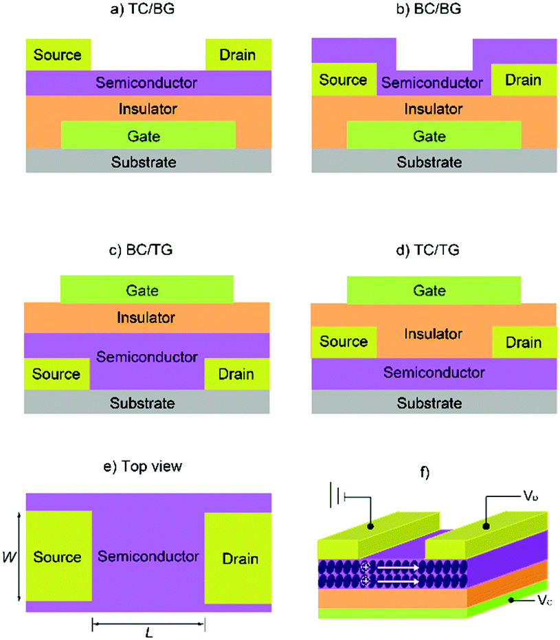 | ||
| Fig. 6 Four typical OFET configurations: (a) top contact, bottom gate (TC/BG); (b) bottom contact, bottom gate (BC/BG); (c) bottom contact, top gate (BC/TG); (d) top contact, top gate (TC/TG). (e) The top view of source-and-drain electrodes and semiconductor layer. (f) A thin-film transistor with a flat film as the charge-transporting layer. The image (f) is reprinted with permission from ref. 163. Copyright 2011, Wiley-VCH. | ||
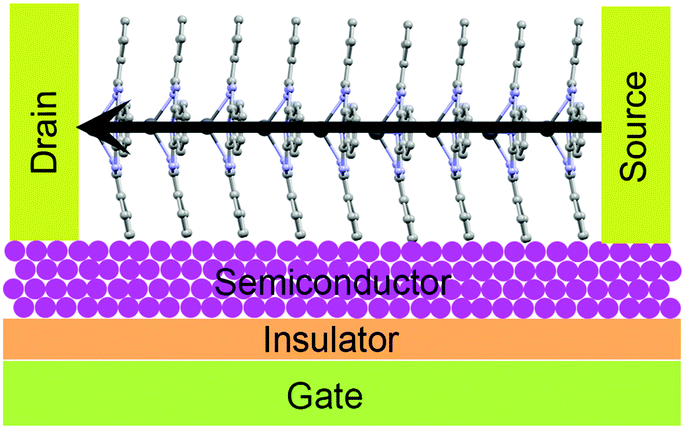
The basic principle behind OFETs involves modulation of the current between the S/D electrodes by application of a voltage to the gate electrode. A bias (VDS) is applied between the S/D electrodes, and depending on the gate voltage (VG), current flows through the semiconductor layer. When no VG or a small VG is applied, only negligible current flows across the semiconductor due to a lack of mobile charge carriers. This state is called the device “off” state. If the applied VG is larger than the threshold voltage (VT) of the device, charge carriers can be electrostatically induced and the current flow (ID) between the S/D electrodes increases, thus the device is “turned on”. During this process, specific charge carriers will transfer between the S/D electrodes, which is oriented parallel to the substrate surface. In order to achieve this, molecules in the semiconductor layer are required to “stand” on the substrate to ensure the π–π stacking direction is parallel to the substrate.164 An OFET-device based on the film with vertical channels with respect to the substrate for charge transport is shown in Fig. 6f. When a negative gate voltage is applied, positive charges (i.e., holes) act as charge carriers; such transistors are defined as p-channel (or p-type) OFETs and the corresponding semiconductor in the active layer is a p-type semiconductor. Conversely, an n-channel (or n-type) OFET occurs when a positive gate voltage is applied and negative charge carriers (i.e., electrons) flow through the active material. In this case the organic semiconductor is defined as n-type. In some cases, ambipolar charge transport in single component OFETs can be realised by reducing the injection barrier of holes and electrons.
Related to MPc-based OFETs, some common features are noted. For example, the substrate is often treated with octyltrichlorosilane (OTS)38,163,165 or parasexiphenyl (p-6p)165 as it has been demonstrated that Pc molecules tend to grow larger domains on OTS or p-6p modified substrates. This leads to reduced grain boundaries, thereby enhancing charge transfer mobility (μ) and thus better device performance.166–168 With respect to the insulating layer, to ensure sufficient charge carriers are present at the interface when a gate voltage is applied, a high dielectric strength material is necessary. While some polymers such as polymethyl methacrylate (PMMA)169 have been reported, silicon dioxide (SiO2) is by far the most commonly employed insulator. Given MPcs can act as either p-type or n-type semiconductors (depending on the choice of central atom and functionalisation of the Pc backbone, vide infra), variation in S/D electrodes is common. For the purpose of achieving sufficient injection efficiency, the work function of electrodes should be compatible with the energy levels of the frontier molecular orbitals of the semiconductor (Fig. 7), and is therefore highly dependent on the active material. For OFETs with p-type organic semiconductors as the active channel material, high work function metals such as silver (∼−4.7 eV), gold (∼−5.1 eV), and platinum (∼−5.6 eV) are often employed as the S/D electrodes, as their work functions are comparable to the HOMO of most of p-type channel materials (usually from −4.9 to −5.5 eV).170 On the other hand, in order to match the LUMO of n-type channel materials (usually from −3 to −4.5 eV) and achieve efficient charge injection, low work function metals such as calcium (∼−2.87 eV)171 are also used in OFET devices. In some cases, using asymmetric electrodes, e.g., Au electrode for hole injection and a Ca electrode172 for electron injection in the same device, leads to ambipolar behaviour for semiconductors.
 | ||
| Fig. 7 The compatible relationship between the work function of S/D electrodes and the HOMO/LUMO of the semiconductor material. | ||
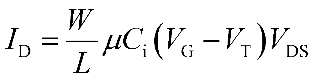 | (1) |
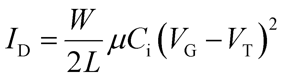 | (2) |
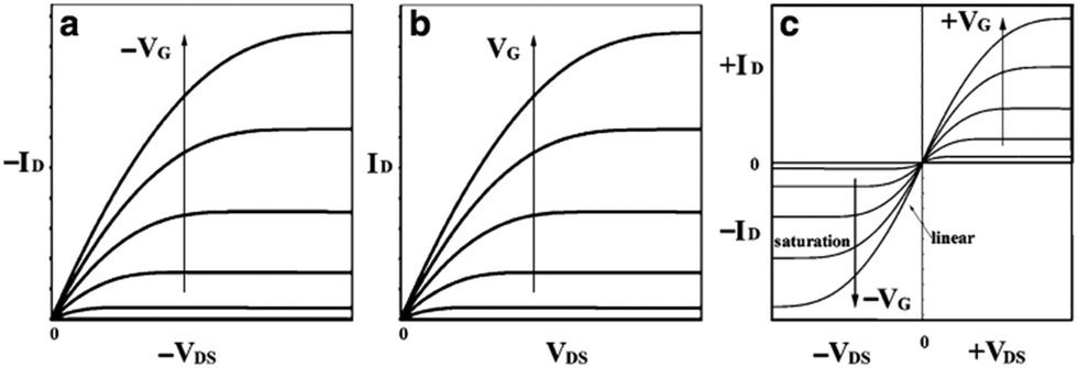 | ||
| Fig. 8 Schematic diagram of current–voltage characteristics of (a) p-type, (b) n-type, and (c) ambipolar OFET device. Reprinted by permission from Springer Nature. 156 Copyright 2010. | ||
Apart from μ, VT, and Ion/Ioff, the stability is also an important aspect while evaluating the performance of OFET devices. To obtain air-stable and high-performing OFETs, appropriate HOMO or LUMO energy levels of the active material is required. The energy of the HOMO (EHOMO) for p-type organic semiconductors is usually in the range of −4.9 to −5.5 eV, which should be high enough with respect to the work function of electrode to achieve a low hole injection barrier thereby a low VT, but not too large to avoid being oxidised by air (below −4.0 eV). Compared to p-channel counterparts, it is well known that n-channel OFET devices are much more air-sensitive due to the intrinsic instability of organic radical anions under ambient conditions.173 As such, most n-type OFETs can only operate under vacuum or an inert atmosphere. Such unacceptable instability towards air, however, can be improved by lowering the energy level of the semiconductor LUMO below −4.0 eV.174 This can be achieved by functionalizing p-type materials with electron-withdrawing groups such as halogen atoms31,175–178 or cyano groups,179–182 thereby efficiently converting them into n-type semiconductors. Alternatively, introducing pyrazine into the framework of conjugated molecules not only maintains molecular planarity but also decreases the EHOMO and ELUMO, thereby increasing air stability and electron injection affording n-channel materials.183 Inclusion of a six-membered imide ring into aromatic diimides can also lead to potential n-type semiconducting materials with promising air stability.173 Interestingly, in some reports of metal phthalocyanines as the active layer in OFETs, the transition from unipolar n-type to ambipolar38 or even to p-type semiconductor171 was observed, with the p-type conduction increasing after exposing the device to air for several minutes. That behaviour is potentially due to oxygen in air acting as an electron acceptor from the central ion, thereby creating holes in some molecules.38 Apart from that, a series of processing parameters including the processing technique (e.g., solution processing, thermal vapor deposition), substrate temperature, annealing, etc. can also influence OFET performance by affecting thin film morphology. Studies of the impact of these parameters on the performance of MPc-based OTFTs has been summarised by Bender, Lessard and co-workers in detail in their review article.21
While these μs are comparable to devices utilizing benchmark organic semiconductors like pentacene, improvements on overall device performance for these systems is limited from a molecular design approach. A caveat amongst many MPcs with divalent transition metal centres is, for the most part, the lack of tuneable substituents bound to the central ion, which can be used to manipulate the solid-state packing in particular. In general, divalent MPcs tend to assemble in edge-to-face herringbone motifs, reducing π-orbital overlap and consequentially leading to moderate charge mobilities. Conversely, when these substituents are present, the axial ligands can direct MPcs into face-to-face π-stacking assemblies, which in turn can strengthen pathways for charge transport.31,32,162,188,189
To reap the benefits provided from axial functionalities, attention has been drawn towards main-group Pcs, as a range of stable oxidation states can be accessed from these elements. Trivalent and tetravalent main-group Pcs are in possession of one and two chemical handles, respectively, that can be easily modified for tuning of the material properties. Moreover, higher valencies and greater electronegativities found for many of the p-block elements has been shown to intrinsically affect the nature of the organic semiconductor, from which unipolar n-type and ambipolar behaviours have been observed for unsubstituted Pc complexes. In this section, we provide a view of the OFET performances for devices fabricated with main-group Pcs of groups 13 (B, Al, Ga and In) and 14 (Si, Ge, Sn, and Pb). Interestingly, there are currently no reports of main-group Pcs with thallium or group 15 elements in the application of OFETs, to the best of our knowledge, despite their chemistry being established.
3.2 Group 13 phthalocyanines in OFETs
Key parameters from the performances of OTFTs fabricated from group 13 main-group Pcs have been tabulated in Table 1. Among this group, X-BSubPc derivatives have been widely employed as functional materials in OLEDs and OPVs,20,22 however, there remains a paucity of research on their role in OFETs. In 2007, Yasuda and Tsutsui reported the fabrication of OTFT devices using Cl-BSubPc within the active layer.171 Metal calcium was utilised for the S/D electrodes with an Ag overlayer, as its low work function reduces electron injection barriers. OFETs, with Cl-BSubPc deposited by vacuum sublimation, exhibited n-channel behaviour with an electron μ of 5.4 × 10⁻⁵ cm2 V−1 s−1 and VT of 11 V. For reference, devices were also constructed using Au for the S/D electrodes, which showed a drop in the mobility (μ = 1.2 × 10⁻⁵ cm2 V−1 s−1) and rise in the threshold voltage (VT = 45 V). At the time, the reference OFET with Au S/D electrodes showed a curious ambipolar behaviour when expose to air for a few minutes with a field-effect hole μ reaching 7.5 × 10⁻⁷ cm2 V−1 s−1; however, since then, this type of charge carrier μ is well accepted in X-BSubPcs, as shown in their fabrication into OPVs.22| Organic semiconductor | Gate/insulator | Inducing layer | S/D contact | Structure | Deposit temp. (°C) | Type (n/p) | V T (V) | μ (cm2 V−1 s−1) | I on/Ioffa | Ref. |
|---|---|---|---|---|---|---|---|---|---|---|
| a S/D: source and drain electrodes; μ: best reported carrier (hole for p-channel, electron for n-channel) mobility; VT: best reported threshold voltage; Ion/Ioff: on/off current ratio. b Commercially available. c Prepared in the lab. d Performed in air. | ||||||||||
| Cl-BSubPcb | Au/parylene-C | None | Ca/Ag | TC/BG | N/A | n | 11 | 5.4 × 10⁻⁵ | N/A | 171 |
| Cl-BSubPcb | Au/parylene-C | None | Au | TC/BG | N/A | n | 45 | 1.2 × 10⁻⁵ | N/A | 171 |
| Cl-BSubPcbd | Au/parylene-C | None | Au | TC/BG | N/A | p | N/A | 7.5 × 10⁻⁷ | N/A | 171 |
| Cl-AlPcb | Si/SiO2 | None | N/A | TC/BG | 25 | p | N/A | 1 × 10⁻⁴ | N/A | 163 |
| Cl-AlPcb | Si/SiO2 | None | N/A | TC/BG | 120 | p | N/A | 1 × 10⁻⁶ | N/A | 163 |
| Cl-AlPcb | Si/SiO2 | OTS | N/A | TC/BG | 120 | p | N/A | 6 × 10⁻² | N/A | 163 |
| Cl-AlPcb | Si/SiO2 | OTS | Au | BC/BG | 120 | p | −13.6 | 1 × 10⁻³ | 104 | 33 |
| Cl-AlPcbd | Si/SiO2 | OTS | Au | BC/BG | 120 | p | 2 | 4 × 10⁻² | 104 | 33 |
| Cl-Al(F16)Pcc | Grid/Ta2O5 or SiO2 or Al2O3 | OTS | Al | TC/BG | 25–250 | n | N/A | 1.2 × 10⁻² | 105 | 165 |
| Cl-Al(F16)Pcc | Grid/Ta2O5 or SiO2 or Al2O3 | p-6p | Al | TC/BG | 25–250 | n | N/A | 2.3 × 10⁻² | 105 | 165 |
| Cl-Al(F16)Pcc | Grid/Ta2O5 or SiO2 or Al2O3 | OTS | Au | TC/BG | 25–250 | n | N/A | 1.0 × 10⁻² | 105 | 165 |
| Cl-Al(F16)Pcc | Grid/Ta2O5 or SiO2 or Al2O3 | p-6p | Au | TC/BG | 25–250 | n | N/A | 1.7 × 10⁻² | 105 | 165 |
| Cl-Al(Cl16)Pcc | Grid/Ta2O5 or SiO2 or Al2O3 | OTS | Al | TC/BG | 25–250 | n | N/A | 1.4 × 10⁻² | 105 | 165 |
| Cl-Al(Cl16)Pcc | Grid/Ta2O5 or SiO2 or Al2O3 | p-6p | Al | TC/BG | 25–250 | n | N/A | 2.2 × 10⁻² | 105 | 165 |
| Cl-Al(Cl16)Pcc | Grid/Ta2O5 or SiO2 or Al2O3 | OTS | Au | TC/BG | 25–250 | n | N/A | 1.3 × 10⁻² | 105 | 165 |
| Cl-Al(Cl16)Pcc | Grid/Ta2O5 or SiO2 or Al2O3 | p-6p | Au | TC/BG | 25–250 | n | N/A | 1.7 × 10⁻² | 105 | 165 |
| HO-Al(SO3Na)1.5Pcc | Si/SiO2 | None | Cr/Au | N/A | — | p | −1.42 | 2 × 10⁻² | 103 | 190 |
| HO-Al(SO3Na)1.5Pcc | Al/SiO2 | None | Cr/Au | N/A | — | p | −1.42 | 2 × 10⁻² | 103 | 191 |
| Cl-GaPcb | Grid/Ta2O5 or SiO2 or Al2O3/PMMA | None | Au | TC/BG | 25–250 | p | N/A | 1 × 10⁻² | 105 | 165 |
| Cl-InPcb | PET with ITO/nylon 11 and Al2O3 | None | Ag | TC/BG | 24 | p | 0.59 | 36.2 | N/A | 192 |
| Cl-InPcb | Grid/Ta2O5 or SiO2 or Al2O3/PMMA | None | Au | TC/BG | 25–250 | p | N/A | 2.5 × 10⁻² | 105 | 165 |
| F-InPcc | Grid/Ta2O5 or SiO2 or Al2O3 | OTS | Al | TC/BG | 25–250 | n | N/A | 1 × 10⁻² | 105 | 165 |
| F-InPcc | Grid/Ta2O5 or SiO2 or Al2O3 | p-6p | Al | TC/BG | 25–250 | n | N/A | 1.8 × 10⁻² | 105 | 165 |
| F-InPcc | Grid/Ta2O5 or SiO2 or Al2O3 | OTS | Au | TC/BG | 25–250 | n | N/A | 5.1 × 10⁻² | 105 | 165 |
| F-InPcc | Grid/Ta2O5 or SiO2 or Al2O3 | p-6p | Au | TC/BG | 25–250 | n | N/A | 7.4 × 10⁻² | 105 | 165 |
| Cl-In(F16)Pcc | Grid/Ta2O5 or SiO2 or Al2O3 | OTS | Al | TC/BG | 25–250 | n | N/A | 1.5 × 10⁻² | 105 | 165 |
| Cl-In(F16)Pcc | Grid/Ta2O5 or SiO2 or Al2O3 | p-6p | Al | TC/BG | 25–250 | n | N/A | 2.1 × 10⁻¹ | 105 | 165 |
| Cl-In(F16)Pcc | Grid/Ta2O5 or SiO2 or Al2O3 | OTS | Au | TC/BG | 25–250 | n | N/A | 1.2 × 10⁻² | 105 | 165 |
| Cl-In(F16)Pcc | Grid/Ta2O5 or SiO2 or Al2O3 | p-6p | Au | TC/BG | 25–250 | n | N/A | 2.7 × 10⁻¹ | 105 | 165 |
| Cl-In(Cl16)Pcc | Grid/Ta2O5 or SiO2 or Al2O3 | OTS | Al | TC/BG | 25–250 | n | N/A | 1.5 × 10⁻² | 105 | 165 |
| Cl-In(Cl16)Pcc | Grid/Ta2O5 or SiO2 or Al2O3 | p-6p | Al | TC/BG | 25–250 | n | N/A | 1.9 × 10⁻² | 105 | 165 |
| Cl-In(Cl16)Pcc | Grid/Ta2O5 or SiO2 or Al2O3 | OTS | Au | TC/BG | 25–250 | n | N/A | 1.6 × 10⁻¹ | 105 | 165 |
| Cl-In(Cl16)Pcc | Grid/Ta2O5 or SiO2 or Al2O3 | p-6p | Au | TC/BG | 25–250 | n | N/A | 2.1 × 10⁻¹ | 105 | 165 |
Apart from this work, Bender and co-workers investigated the basic electron mobilities of a series of fluorinated phenoxy BSubPcs (i.e., (F5PhO)-BSubPc, (PhO)-B(F)16SubPc, and (F5PhO)-B(F)16SubPc) using admittance spectroscopy.193 At high electric fields, mobilities reached approximately 10−4 cm2 V−1 s−1, which are higher than that reported for Cl-BSubPcs. Although these mobilities were not determined for OTFTs, but rather sandwiched between two electrodes perpendicular to the substrate, investigations into the axial ligands in X-BSuBPc warrants further attention to improve OTFT performances based on these systems.
Cl-AlPc, a nonplanar and pyramid-like trivalent phthalocyanine, has been used as in the semiconductor layer of OFET devices in many reports. Compared to the most commonly used planar divalent Pcs such as CuPc, Cl-AlPc forms a face-to-face π-stacked structure that leads to more-efficient π-orbital overlap, facilitating charge carrier transport.163 Recently, Boileau et al.33 reported the impact of environmental pressure and operating temperature on charge transport and electrical stability of p-type BC/BG OTFTs based on Cl-AlPc semiconductor layer. The hole μ increased from 0.001 cm2 V−1 s−1 in vacuum to 0.04 cm2 V−1 s−1 in air, indicating that the oxygen present under ambient conditions coordinates to the surface Cl-AlPc metal centres, which will act as an electron acceptor/trap and increase positive charge carrier density in the bulk film as a result.33,171Fig. 9 shows how hole μ changes with VGS at different device testing temperatures under either vacuum (a, 25–150 °C) or air (b, 25–85 °C) ambience. In general, the μ increases with increasing temperature in vacuum, while in air it shows minimal change. Besides, under vacuum, the higher the temperature applied, the lower voltage (VT) is required to turn the transistor on. However, this overall shift in curves with increasing temperature (ΔVT) is less obvious in air. In the same paper, Boileau et al.33 also investigated five other divalent transition-metal Pcs, including ZnPc, MgPc, FePc, CoPc and CuPc. Fig. 10 illustrates ΔVT and percentage changes in μ of different MPcs. The result indicates that divalent MPcs show generally greater changes in μ and VT in performance with temperature by comparison with Cl-AlPc. In other words, Cl-AlPc film has more air-stable electrical properties. This is attributed to its distinct film morphologies with larger grain sizes and higher surface roughness, leading to lower surface area to volume ratios and thus reducing the access of ambient gases to the overall volume, based on the atomic force microscope (AFM) results (Fig. 11).
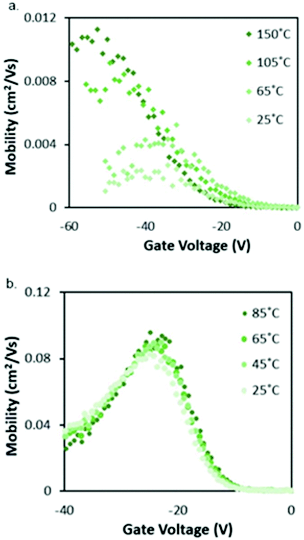 | ||
| Fig. 9 Characterisation of Cl-AlPc OTFTs. (a) VGSvs. μ curves at temperatures ranging from 25 °C to 150 °C in vacuum. (b) VGSvs. μ curves at temperatures ranging from 25 °C to 85 °C in air. Reproduced from ref. 33 with permission from The Royal Society of Chemistry. | ||
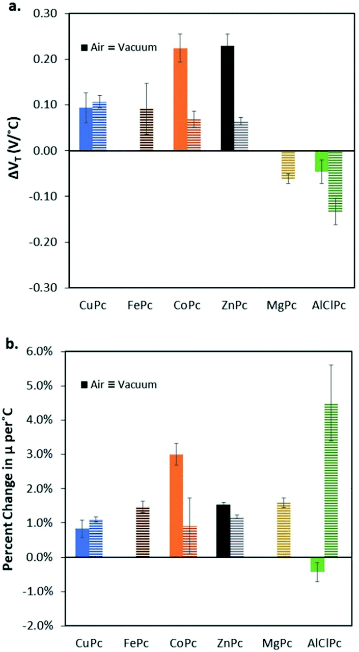 | ||
| Fig. 10 (a) Change in threshold voltage per degree celsius, (VT/°C) within the characterised temperature range (25 °C to 85 °C for air and 25 °C to 150 °C for vacuum) for each phthalocyanine material (bule: CuPc; brown: FePc; orange: CoPc; black: ZnPc; yellow: MgPc; green: Cl-AlPc) characterised in BC/BG OTFT under air (solid bars), and vacuum (horizontal line bars). (b) % change in hole mobility, μ, compared to baseline at 25 °C per °C. Materials that did not function in air have no corresponding data (FePc, and MgPc). Reproduced from ref. 33 with permission from The Royal Society of Chemistry. | ||
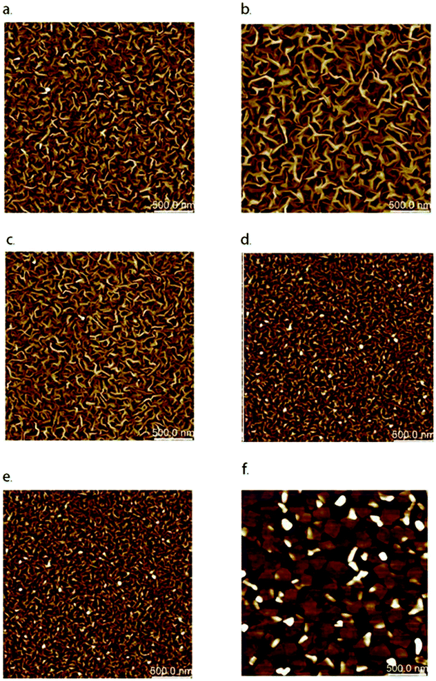 | ||
| Fig. 11 AFM images (2.5 mm × 2.5 mm) of (a) CuPc (b) FePc (c) CoPc (d) ZnPc (e) MgPc (f) Cl-AlPc deposited on heated silicon substrates. Reproduced from ref. 33 with permission from The Royal Society of Chemistry. | ||
As previously mentioned, the semiconductor layer can be deposited using different approaches. Since most MPcs have poor solubility, MPc based OFETs are commonly fabricated by vacuum evaporation. To develop a device using solution processing, Glezos and co-workers synthesised water-soluble aluminium complexes by sulfonating unsubstituted HO-AlPc with fuming sulfuric acid.190,191 The crude product was a mixture of mono-, di-, tri- and tetra-sulfonated isomers of HO-Al(HO3S)mPc (m = 1–4), which was separated by column liquid chromatography, and subsequently treated with NaOH to afford their fully deprotonated sodium salts. Thin films of HO-Al(NaO3S)mPcs were analysed by X-ray photoelectron spectroscopy, from which the atomic ratios of the elements detected on the surface of the spin-casted material indicated a chemical composition reflecting that of HO-Al(NaO3S)1.5Pcs. This was believed to arise from the atmospheric exposure upon processing the material onto the substrate. p-Channel OFET devices based on HO-Al(NaO3S)1.5Pcs exhibited field-effect mobilities of 0.02 cm2 V−1 s−1, VT of −1.42 V and ∼103 current on/off ratios.
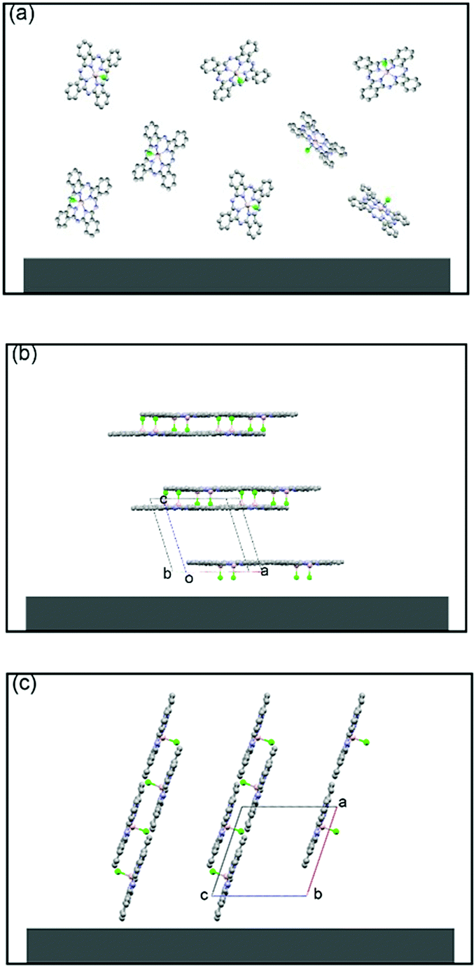
In 2011, Chi and co-workers investigated the molecular packing mode and optoelectronic properties of Cl-AlPc which was utilised as the semiconductor layer in TC/BG OTFT devices fabricated on pure SiO2 substrate at room temperature and 120 °C, and on an OTS-treated surface at 120 °C.163 The output and transfer characteristics of these devices are illustrated in Fig. 12, which reveal inferior hole mobilities for the devices fabricated on SiO2 (10−4 cm2 V−1 s−1 for room temperature, and 10−6 cm2 V−1 s−1 for 120 °C) compared to that of devices employing OTS-modified substrates (0.06 cm2 V−1 s−1 for 120 °C). This difference in device performance is related to the molecular orientation of the molecules on the three substrates. As shown in Fig. 13c, when Cl-AlPc molecules are depositing on an OTS-modified surface, they align with an inclination angle of 18.2° with respect to the surface normal, resulting in continuous and flat films. Compared with random or face-on molecular orientations that were formed on the SiO2 surface (Fig. 13a and b), this edge-on orientation is much more favourable for in-plane charge transport due to the reduced grain boundary and the consistency between the charge-transport direction and the π-stacking direction.163 It can therefore be concluded that high-performance OTFTs can be obtained by tuning the surface properties and substrate temperature to control the growth of the film with appropriate packing mode.
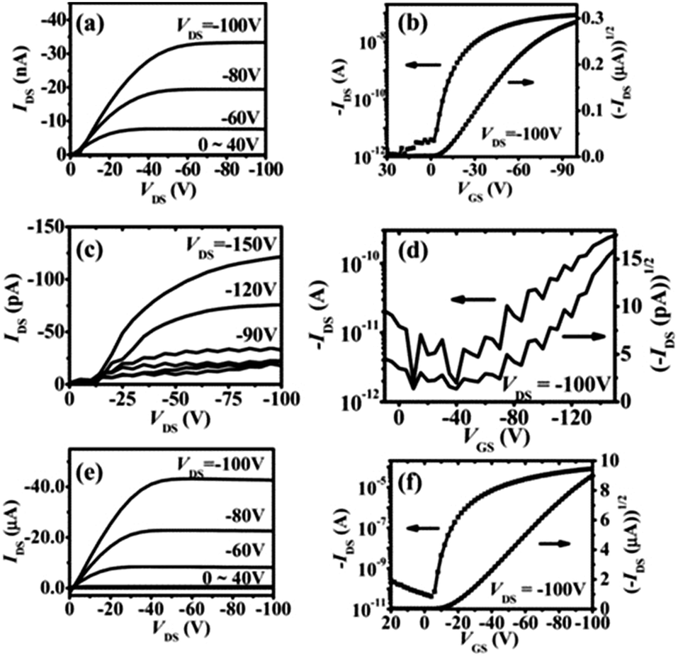 | ||
| Fig. 12 Output and transfer curves of devices with Cl-AlPc active layer fabricated under different conditions: (a and b) pure SiO2 surface at room temperature; (c and d) pure SiO2 surface at 120 °C; (e and f) OTS-modified surface at 120 °C. The image is reprinted with permission from ref. 163. Copyright 2011, Wiley-VCH. | ||
 | ||
| Fig. 13 Schematic molecular packing of a Cl-AlPc (CCDC: 1134071) film fabricated on a pure SiO2 substrate at room temperature (a) and 120 °C (b), and on an OTS-modified surface at 120 °C (c). The image is reprinted with permission from ref. 163. Copyright 2011, Wiley-VCH. | ||
Hexadecafluoro- and hexadecachloro-substituted Cl-AlPcs and Cl-InPcs in OTFTs have also been reported.165 Those derivatives exhibited n-type behaviour with varied electron mobilities, depending on the choice of central ion, S/D electrodes and surface modification layers (p-6p or OTS). In addition, the only data regarding Cl-GaPc as the semiconductor layer in OFETs was reported in the same article.165 The electron μ was 0.01 cm2 V−1 s−1. Other properties such as types of the carriers, the carrier μ, and on/off current ratio of thin-film transistor are listed in Table 1. No more analysis was provided in this article.
Hamui and co-workers prepared a high-performance OFET with a μ of 36.2 cm2 V−1 s−1 and a VT of 0.59 eV by employing Cl-InPc as a p-type semiconductor and including a bilayer gate dielectric consisting of poly(ethylene terephthalate) (PET) and indium-tin oxide (ITO).192 Within a short potential window, the device quickly responded to an increase in the gate voltage to −5.6 V resulting in a minimum μ of 3.2 cm2 V−1 s−1. The gate voltage was further increased to −12 V, from which a second maximum μ of 5.9 cm2 V−1 s−1 was observed. The improved μ was attributed to the bilayer structure and the ability for Cl-InPc to be an effective hole carrier through the extensive π-system.
3.3 Group 14 phthalocyanines in OTFTs
For group 14 main-group Pcs, their performances in OTFTs have been tabulated in Table 2. Tetravalent MPcs with group 14 elements are of increasing interest in the field of organic electronics due in part to the presence of two axial substituents that can be modified. Not only can these be tailored to enhance solubility, but they can also be functionalised to augment the solid-state arrangement and thin film packing of the molecules. Furthermore, recent studies have demonstrated that X2-SiPcs exhibit promising n-type mobilities, offering an alternative to the widely employed fullerene base acceptors.194,195| Organic semiconductor | Gate/insulator | Inducing layer | Structure | Deposit temp. (°C) | S/D contacta | Type (n/p) | V T (V) | μ (cm2 V−1 s−1) | I on/Ioffa | Ref. |
|---|---|---|---|---|---|---|---|---|---|---|
| a S/D: source and drain electrodes; μ: best reported carrier (hole for p-channel, electron for n-channel) mobility; VT: best reported threshold voltage; Ion/Ioff: on/off current ratio; PVA: polyvinyl alcohol. b Commercially available. c Prepared in the lab. d or SiO2 or Al2O3. e Performed in dark. f Performed in light. | ||||||||||
| (PhCOO)2-SiPcc | Si/SiO2 | Plasma | BC/BG | 200 | Au | n | 26.3 ± 3.2 | 5.55 × 10⁻⁴ | 102–103 | 32 |
| (PhCOO)2-SiPcc | Si/SiO2 | OTS | BC/BG | 200 | Au | n | 26.9 ± 2.9 | 1.07 × 10⁻² | 104–105 | 32 |
| (PhCOO)2-SiPcc | Si/SiO2 | ODTS | BC/BG | 200 | Au | n | 21.3 ± 2.1 | 1.35 × 10⁻² | 103–105 | 32 |
| (PhCOO)2-SiPcc | Si/SiO2 | FOTS | BC/BG | 200 | Au | n | 22.2 ± 1.7 | 8.56 × 10⁻⁵ | 102–104 | 32 |
| (1-NpCOO)2-SiPcc | Si/SiO2 | Plasma | BC/BG | 100 | Au | n | 17.5 ± 2.7 | 3.28 × 10⁻⁴ | 102–103 | 32 |
| (9-AnCOO)2-SiPcc | Si/SiO2 | Plasma | BC/BG | 100 | Au | n | 15.0 ± 0.6 | 5.56 × 10⁻⁵ | 101–102 | 32 |
| Cl2-SiPcb | Si/SiO2 | OTS | BC/BG | 140 | Au/ITO | n | 37.2 ± 14.1 | 9.73 × 10⁻² | 105 | 38 |
| (2,4,6-F3PhO)2-SiPcc | Si/SiO2 | OTS | BC/BG | 140 | Au/ITO | n | 35.2 ± 3.4 | 4.31 × 10⁻² | 104–105 | 38 |
| (3,4,5-F5PhO)2-SiPcc | Si/SiO2 | OTS | BC/BG | 140 | Au/ITO | n | 17.1 ± 7.5 | 3.14 × 10⁻² | 104–105 | 38 |
| (F5PhO)2-SiPcc | Si/SiO2 | OTS | BC/BG | 140 | Au/ITO | n | 12.0 ± 4.8 | 5.37 × 10⁻¹ | 104–105 | 38 |
| (F5PhO)2-SiPcc | Si/SiO2 | OTS | TC/BG | 25 | Au | n | 23.5 ± 0.4 | 2.7 × 10⁻¹ | N/A | 34 |
| (F5PhO)2-SiPcc | Si/SiO2 | OTS | TC/BG | 25 | Au/Cr | n | 13.4 ± 1.4 | 1.5 × 10⁻¹ | N/A | 34 |
| (F5PhO)2-SiPcc | Si/SiO2 | OTS | TC/BG | 25 | Au/Mn | n | 10.0 ± 2.1 | 1.9 × 10⁻¹ | N/A | 34 |
| (F5PhO)2-SiPcc | Si/SiO2 | OTS | TC/BG | 25 | Au/BCP | n | 12.4 ± 1.3 | 1.8 × 10⁻¹ | N/A | 34 |
| (F5PhO)2-SiPcc | Si/SiO2 | OTS | TC/BG | 25 | Ag | n | 28.7 ± 1.7 | 1.7 × 10⁻¹ | N/A | 34 |
| (F5PhO)2-SiPcc | Si/SiO2 | OTS | TC/BG | 25 | Ag/Cr | n | 20.8 ± 2.1 | 9.0 × 10⁻² | N/A | 34 |
| (F5PhO)2-SiPcc | Si/SiO2 | OTS | TC/BG | 25 | Ag/Mn | n | 7.8 ± 1.4 | 1.7 × 10⁻¹ | N/A | 34 |
| (F5PhO)2-SiPcc | Si/SiO2 | OTS | TC/BG | 25 | Ag/BCP | n | 23.9 ± 1.6 | 2.1 × 10⁻¹ | N/A | 34 |
| ((Bu)3SiO)2SiPc | Si/SiO2 | OTS | BC/BG | 100 | Au/ITO | n | 21.8 ± 1.8 | 14.4 × 10⁻⁵ | 102–103 | 151 |
| ((Bu)3SiO)2SiPc | Si/SiO2 | OTS | BC/BG | 150 | Au/ITO | n | 21.8 ± 0.69 | 159 × 10−5 | 102–103 | 151 |
| ((Hx)3SiO)2SiPc | Si/SiO2 | OTS | BC/BG | 100 | Au/ITO | n | 22.4 ± 1.0 | 2.66 × 10⁻⁵ | 10–104 | 151 |
| ((Hx)3SiO)2SiPc | Si/SiO2 | OTS | BC/BG | 150 | Au/ITO | n | 25.4 ± 1.1 | 1.62 × 10⁻⁵ | 10–103 | 151 |
| Cl2-GePcb | Grid/Ta2O5d | OTS | TC/BG | 25–250 | Au | p | N/A | 6.1 × 10⁻² | 105 | 165 |
| Cl2-GePcb | Grid/Ta2O5d | p-6P | TC/BG | 25–250 | Au | p | N/A | 9.0 × 10⁻¹ | 105 | 165 |
| SnPcb | Au/SiO2 | None | BC/BG | 30 | Au | p | N/A | 7.3 × 10⁻⁵ | N/A | 196 |
| SnPcb | Au/SiO2 | None | BC/BG | 125 | Au | p | N/A | 3.4 × 10⁻⁵ | N/A | 196 |
| SnPcb | Au/SiO2 | None | BC/BG | 200 | Au | p | N/A | No field effect | N/A | 196 |
| Cl2-SnPcb | Al/SiO2 | None | TC/BG | 60 | Ag | n | 4 | 1.0 × 10⁻² | 104 | 161 |
| Cl2-SnPcb | Si/SiO2 | p-6P | TC/BG | 180 | Au | n | 27 | 3.0 × 10⁻¹ | 106 | 162 |
| O-SnPcb | Si/SiO2 | p-6P | TC/BG | 180 | Au | n | 37 | 4.4 × 10⁻¹ | 103 | 166 |
| ((Bu)3SiO)2SiPc | Si/SiO2 | OTS | BC/BG | 100 | Au/ITO | n | 0.21 ± 0.68 | 44.0 × 10⁻⁵ | 10 | 151 |
| ((Bu)3SiO)2SiPc | Si/SiO2 | OTS | BC/BG | 150 | Au/ITO | n | −2.90 ± 1.2 | 9.16 × 10⁻⁵ | 1–10 | 151 |
| ((Hx)3SiO)2SiPc | Si/SiO2 | OTS | BC/BG | 100 | Au/ITO | n | 9.26 ± 1.1 | 12.6 × 10⁻⁵ | 10–102 | 151 |
| ((Hx)3SiO)2SiPc | Si/SiO2 | OTS | BC/BG | 150 | Au/ITO | n | 6.79 ± 0.97 | 17.6 × 10⁻⁵ | 10–102 | 151 |
| Cl2-Sn(F16)Pcc | Si/SiO2 | p-6P | TC/BG | 180 | Au | n | 7.62 | 8.5 × 10⁻⁴ | N/A | 197 |
| Cl2-Sn(F16)Pcc | Grid/Ta2O5d | OTS | TC/BG | 25–250 | Al | n | N/A | 1.0 × 10⁻² | 105 | 165 |
| Cl2-Sn(F16)Pcc | Grid/Ta2O5d | p-6P | TC/BG | 25–250 | Al | n | N/A | 1.1 × 10⁻¹ | 105 | 165 |
| Cl2-Sn(F16)Pcc | Grid/Ta2O5d | OTS | TC/BG | 25–250 | Au | n | N/A | 1.3 × 10⁻² | 105 | 165 |
| Cl2-Sn(F16)Pcc | Grid/Ta2O5d | p-6P | TC/BG | 25–250 | Au | n | N/A | 2.4 × 10⁻¹ | 105 | 165 |
| Cl2-Sn(F16)Pcc | Grid/Ta2O5d | OTS | TC/BG | 25–250 | Al | n | N/A | 1.2 × 10⁻² | 105 | 165 |
| Cl2-Sn(F16)Pcc | Grid/Ta2O5d | p-6P | TC/BG | 25–250 | Al | n | N/A | 1.7 × 10⁻² | 105 | 165 |
| Cl2-Sn(F16)Pcc | Grid/Ta2O5d | OTS | TC/BG | 25–250 | Au | n | N/A | 2.3 × 10⁻² | 105 | 165 |
| Cl2-Sn(F16)Pcc | Grid/Ta2O5d | p-6P | TC/BG | 25–250 | Au | n | N/A | 1.7 × 10⁻¹ | 105 | 165 |
| PbPcb | Si/SiO2 | None | TC/BG | N/A | Au | pe | −82e | 1.4 × 10⁻⁵![[thin space (1/6-em)]](https://www.rsc.org/images/entities/char_2009.gif) e e |
N/A | 198 |
| pf | N/Af | 3.0 × 10⁻⁵f |
N/Af | |||||||
| nf | N/Af | 1.8 × 10⁻⁵f |
N/Af | |||||||
| PbPcb | Au/parylene-C | None | TC/BG | N/A | Au | n | 45 | 1.3 × 10⁻³ | N/A | 160 |
| p | −27 | 4.2 × 10⁻³ | N/A | |||||||
| PbPcb | Au/parylene-C | None | TC/BG | N/A | Ca | n | 31 | 2.0 × 10⁻³ | N/A | 160 |
| p | −22 | 1.8 × 10⁻³ | N/A | |||||||
| Pb (C6H13)8Pcc | ITO/PVAa | None | TC/BG | — | Au | p | N/A | N/A | N/A | 199 |
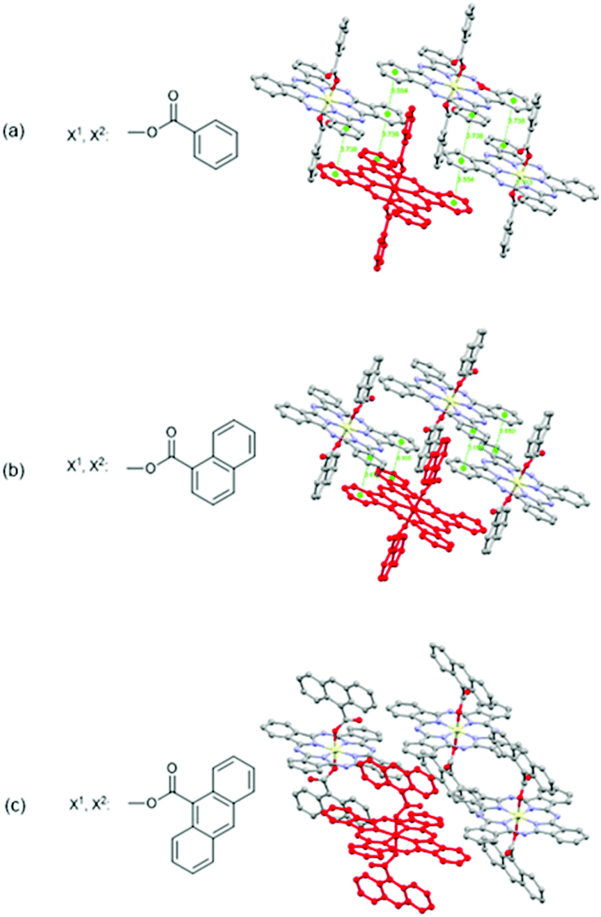
In 2018, Melville et al. reported X2-SiPcs in OTFT application for the first time.32 Specifically, they investigated the use of a series of X2-SiPcs axially functionalised with carboxylates attached to aromatic rings as active materials in OTFTs (Fig. 14a–c). Encouragingly, all derivatives exhibited n-channel behaviour and revealed the importance of the axial substituents on the thin film morphology. The authors noted that an increase in the steric bulk of the aromatic axial substituents was accompanied by a decrease in both the electron μ and Ion/Ioff ratio. The same tendency was also observed with the VT. The structures of the molecules as determined using single crystal X-ray diffraction are shown in Fig. 14. Notably (PhCOO)2-SiPc displays the 2D arrangement of π–π stacking pathways while (1-NpCOO)2-SiPc does not, despite (1-NpCOO)2-SiPc having the closest π–π distance. On the other hand, the structure of (9-AnCOO)2-SiPc possesses little π–π overlap, which may explain why (PhCOO)2-SiPc has the highest μ among those three derivatives. Furthermore, the performance of devices using (PhCOO)2-SiPc was systematically probed through modifications to the dielectric surface treatments. It was observed when trichloro(octyl)silane (OTS) and trichloro(octadecyl)silane (ODTS) were employed, mobilities were enhanced, while the inverse was observed with trichloro(1H,1H,2H,2H-perfluorooctyl)silane (FOTS).
 | ||
| Fig. 14 Chemical structures and solid-state arrangement of three X2-SiPc axially substituted with carboxylates. Molecular overlap with a centroid–centroid distance <4 Å are indicated with dotted green lines. Reproduced from ref. 32 with permission from The Royal Society of Chemistry. | ||
Following that initial report, OTFTs were studied employing SiPcs axially functionalised with pentafluorophenoxy ((F5PhO)2-SiPc), 2,4,6-trifluorophenoxy ((2,4,6-F3PhO)2-SiPc and 3,4,5-trifluorophenoxy (3,4,5-F3PhO)2-SiPc) substituents further revealing the n-type behaviour of SiPcs.38 Devices based on (F5PhO)2-SiPc possessed the highest electron μ (up to 0.5 cm2 V−1 s−1), and currently holds the highest record for all n-type MPcs, along with the lowest VT averaging around 12.0 V. Conversely, Cl2SiPc based devices exhibited the highest VT (up to 37 V) and relatively low μe. These results reveal the importance of the substituents and suggest the addition of the fluorinated phenoxy pendant groups induce π–π overlap. The authors also investigated the effect of characterisation atmosphere on device performance, with all OTFTs characterised at both positive and negative VGS and VDS under vacuum and air conditions. As an example, Fig. 15 shows a sample transfer curve under each condition for material (F5PhO)2-SiPc. The results, listed in Table 3, reveal an interesting phenomenon of increased p-type charge transfer while transferring devices from vacuum to air, except Cl2-SiPc, which did not show a significant field effect for holes under any condition. This change may be attributed to oxygen in air acting as an electron acceptor from the central metal atom, creating holes in some molecules.
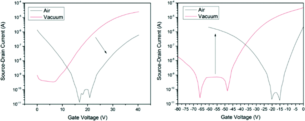 | ||
| Fig. 15 Sample transfer curves for OTFTs using (F5PhO)2-SiPc as the active layer when operated in the electron accumulation region (left) and hole accumulation region (right) and characterised either under vacuum or in air. The image is reprinted with permission from 38. Copyright 2019, Wiley-VCH. | ||
| Organic semiconductor | n-Type (VGS, VDS > 0 V) | p-Type (VGS, VDS < 0 V) | |||
|---|---|---|---|---|---|
| Vacuum | Air | Vacuum | Air | ||
| a Commercially available. b In units of cm2 V−1 s−1. c In units of V. d Prepared in the lab. | |||||
| Cl2-SiPca | μ | 1.55 × 10⁻² | 5.18 × 10⁻⁵ | N/A | N/A |
| V T | 35.3 | 39.9 | N/A | N/A | |
| (F5PhO)2-SiPcd | μ | 4.87 × 10⁻² | 6.40 × 10⁻³ | 4.92 × 10⁻⁵ | 4.16 × 10⁻³ |
| V T | 15.1 | 29.3 | −60.5 | −30.7 | |
| (2,4,6-F3PhO)2-SiPcd | μ | 2.90 × 10⁻² | 2.47 × 10⁻⁵ | 1.51 × 10⁻³ | 1.93 × 10⁻² |
| V T | 32.6 | 45.4 | −45.6 | −26.0 | |
| (3,4,5-F3PhO)2-SiPcd | μ | 1.72 × 10⁻² | 2.95 × 10⁻⁴ | 2.17 × 10⁻⁵ | 2.37 × 10⁻³ |
| V T | 23.3 | 35.1 | −58.4 | −30.3 | |
To enhance device performance and reduce the injection barrier between the organic semiconductor and contacts, Melville et al. have introduced either an electron dopant layer (bathocuproine, BCP) or low-work-function metals (Mn/Cr) between the high work-function electrodes (Au, Ag) and the (F5PhO)2-SiPc semiconductor layer.34 The device structure is shown in Fig. 16, and the saturation region properties are shown in Fig. 17. This study reveals the presence of these interlayers reduces VT, contact resistance and saturation region μ, while improving the linear region mobility (Table 3). The same treatment and characterisation methods were also applied to their tin counterparts, namely (F5PhO)2-SnPc and (2,4,6-F3PhO)2-SnPc.34 The results of this study indicate that Mn and Cr interlayers do not strongly affect performance, while BCP can increase the off-current provided the entire organic semiconductor film is covered. These results were attributed to the larger Sn atom, which has a higher propensity for interaction with BCP than SiPc.
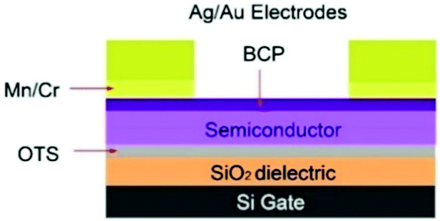 | ||
| Fig. 16 Device schematic for TC/BG OTFTs with either an electron transport (bathocuproine (BCP)) or low-work-function metal (Mn/Cr) interlayer between the main electrode (Ag/Au) and organic semiconductor. Reprinted with permission from ref. 34. Copyright 2020, American Chemical Society. | ||
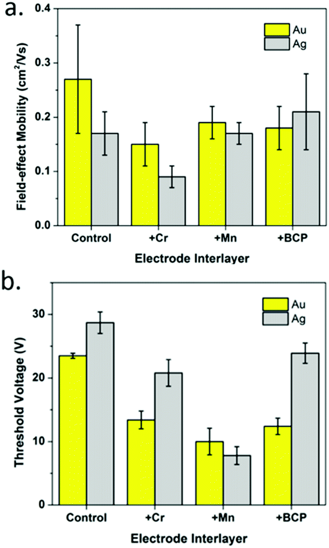 | ||
| Fig. 17 Saturation region properties for OTFTs using (F5PhO)2-SiPc as the semiconductor layer with Au and Ag electrodes and Cr, Mn, or BCP interlayers: (a) field-effect mobility and (b) threshold voltage. Reprinted with permission from ref. 34. Copyright 2020, American Chemical Society. | ||
X2-SnPcs are widely used as n-type semiconductors due to the relatively high electronegativity of tetravalent tin,166 and the closely π-stacked intermolecular motifs that they formed in crystals.127 For example, Giri and co-workers reported that vacuum-deposited Cl2-SnPc OFETs exhibited good n-channel behaviour with electron μ of 0.01 cm2 V−1 s−1, low VT of 4 V, current on/off ratio of 104, and high operation stability with no hysteresis when tested in low vacuum condition.161 Yan and co-workers reported a high-performance air-stable n-type OTFT device based on Cl2-SnPc deposited on a para-sexiphenyl modified substrate with the electron μ of 0.30 cm2 V−1 s−1 and the current on/off ratio of 106.162 After storage in air for 45 days, this device still has a μ up to 0.12 cm2 V−1 s−1 which indicated its excellent stability. Song's group also fabricated another air-stable OTFT based on tin phthalocyanine oxide (O = SnPc).166 An electron μ of 0.44 cm2 V−1 s−1 has been achieved, and it did not obviously change after storage in air for 32 days. The results reveal that incorporating appropriate electron-withdrawing groups such as chloride and oxygen into π-conjugated systems is an effective approach to design air-stable n-type semiconductors. The electron mobilities of OTFT devices based on Cl2-Sn(F)16Pc and Cl2-Sn(Cl)16Pc were reported as well.165 The OTFTs using p-6P modified substrate exhibited approximately 10 times larger μe than that of OTFTs using OTS modified substrate.
Transistor behaviour has also been studied in divalent tin complexes, specifically SnPc. Bao and Lovinger studied the performance of devices with thin films of SnPc vacuum deposited at three temperatures (i.e., 30, 125, 200 °C), from which the material operated as a p-type semiconductor. Average electron mobilities were shown to increase from 30 °C to 125 °C (7.3 × 10⁻⁵ to 3.4 × 10⁻³ cm2 V−1 s−1, respectively) and subsequently exhibited no field-effect when deposition temperatures reached 200 °C. Presumably, better morphological ordering and an enlargement in the size of crystals were attributed to the enhancements in mobilities up to 125 °C, while the presence of large voids appear at higher temperatures.
Reports focusing on GePc derivatives in the application of OFET are less. The only report demonstrates that Cl2-GePc showed p-type results in OTFTs, achieving electron mobilities up to 0.06 and 0.09 cm2 V−1 s−1 on OTS or p-6P modified substrate, respectively.165 As for PbPc, a series of devices have been explored. It is known that a parallel charge transport direction is favourable for high-performance OFETs. In the case of PbPc molecules, the highest conductivity is perpendicular to the molecular plane as shown in Fig. 18.164 Richter and co-workers indicated that an epitaxial-like growth mode of PbPc molecules on reconstructed GaAs(001) surfaces takes place by Raman spectroscopy, which is an important result for OFETs.164 In addition, the relatively low band gap of PbPc (1.2 eV) makes it a good candidate in the application of ambipolar OFETs. For instance, Yasuda et al.160 fabricated OTFT devices based on PbPc semiconductor layer, and both devices with Au or Ca S/D electrodes showed typical ambipolar characteristics. In the case of Au, the field-effect electron μ was calculated to be 8.3 × 10⁻⁴ cm2 V−1 s−1 when the VT was 31 V, while the hole μ was calculated to be 7.1 × 10⁻⁴ cm2 V−1 s−1 when the VT was −58 V. In the case of Ca, an electron μ of 1.3 × 10⁻³ cm2 V−1 s−1 (VT = 36 V) and a hole μ of 4.7 × 10⁻⁴ cm2 V−1 s−1 (VT = −60 V) were estimated from saturation currents. After annealing in the glove box for 12 h at 100 °C, the field-effect mobilities of all the devices increased for both carriers. In addition, Peng et al.198 discovered the photo-induced balanced ambipolar transports in PbPc-based OFETs. As reported, PbPc semiconductor initially behaves p-channel unipolar in the dark due to the significantly lower energy barrier for hole injection (0.1 eV) compared to the energy barrier for electron injection (1.2 eV). However, the electron μ increased to 1.8 × 10⁻⁵ cm2 V−1 s−1 under illumination at 655 nm, 100 mW cm−2, which is very close to the value of the hole μ (3.0 × 10⁻⁵ cm2 V−1 s−1), as the high electron injection barrier was reduced by light illumination. They attribute this to the reduction in electron potential energy from the downward bend of the HOMO and LUMO of PbPc as a consequence of photo-generated holes accumulated near the source electrode. Subsequently, this reduces the electron injection barrier at the S/D interface.198
 | ||
| Fig. 18 The favourable molecular orientation of PbPc in OFETs. The arrows indicate the direction of the highest electrical conductivity. Reprinted figure with permission from ref. 164 Copyright @ 2012, World Scientific. | ||
OFETs based on PbPc derivatives were also reported to be used as non-volatile organic memory device with continuous write-read-erase-read switching performance by Mukherjee et al.199 The device exhibited p-channel behaviour. The introduction of hexyl-substituents in bay positions, as in Pb(n-C6H13)8Pc, efficiently improved the solubility of the material, enabling its ready formulation as thin film by spin-coating. As d, reports focusing on GePc derivatives in the application of OFET are less. The only report demonstrates that Cl2-GePc showed p-type results in OTFTs, achieving electron mobilities up to 0.06 and 0.09 cm2 V−1 s−1 on OTS or p-6P modified substrate, respectively.165
4. Conclusion – outlook
From what began as a chemical curiosity in the investigative studies by Linstead, metal phthalocyanines have since emerged to become, in our opinion, a paramount building block for the development of OTFTs among other applications. The key to MPcs as intrinsic organic semiconductors is tied to the harmonious interplay between the metal ion and the macroaromatic heterocycle. As can be seen through the recent employment of main-group Pcs in these devices, there exists an opportunity to systematically control the behaviour of the material without the necessity for exterior functionalisation. This simply can be harnessed through the range of accessible stable oxidation states and electronegativities of the p-block elements, whereas the degree of this synergy is not fully realised in transition metals. With this said, functionalization at the peripheral, bay and axial positions becomes the “icing on the cake” for main-group Pcs, enabling the fine-tuning of the energetics, enhancing intermolecular interactions and controlling self-assembly on a given substrate. This has been clearly demonstrated in recent reports on various silicon phthalocyanines, from which the ligation of fluorinated phenols has led to materials in possession of ambipolarity, air stability, and the highest field-effect mobilities for n-type MPcs.To take advantage of the attractive features associated with main-group Pcs, considerable attention must be directed to synthetic methodologies in their preparation. The chemistry of main-group Pcs is not new in the slightest; however, unlike transition metals, the relative ease of synthesis becomes increasingly difficult with the introduction of metalloids. This is even more so apparent with non-metals, from which only pentavalent phosphorus has been successfully realized. Despite this, motivation to fabricate OTFTs from MPcs with the relatively unexplored p-block elements has undoubtably steered research efforts towards these challenges. Specifically, for silicon phthalocyanines, derivatisation of the diiminoisoindoline precursor can be readily achieved through the work presented by Brusso and Lessard towards alleviating the strenuous reaction conditions, from which the current benchmark of in n-type MPcs, i.e. (F5PhO)2-SiPc, may soon be superseded. On the other hand, inspiration from the works of Kobayashi and earlier pioneers of phosphorus Pcs may soon draw attention towards the first OTFT fabricated with non-metal Pcs. To this end, this review aims to unmask the hidden potential of main-group phthalocyanines as versatile building blocks in organic thin film transistors.
Conflicts of interest
The authors declare no conflicts of interest.Acknowledgements
This work was supported by the University of Ottawa, the Canadian Foundation for Innovation, the National and Engineering Council of Canada. J. L. B. is grateful to the Ontario Ministry of Research and Innovation for an Early Researcher Award.Notes and references
- P. Gregory, J. Porphyrins Phthalocyanines, 2000, 04, 432–437 CrossRef CAS.
- R. P. Linstead, J. Chem. Soc., 1934, 1016 RSC.
- J. M. Robertson, J. Chem. Soc., 1935, 615 RSC.
- Phthalocyanines, Properties and Applications, ed. C. C. Leznoff and A. B. P. Lever, VCH, Weinheim, Germany, 2012, vol. 1–4 Search PubMed.
- K. Ishii and N. Kobayaski, in The Porphyrin Handbook, ed. K. M. Kadish, K. M. Smith and R. Guilard, Academic Press, New York, 2003, vol. 16, pp. 1–42 Search PubMed.
- J. Mack and M. J. Stillman, in The Porphyrin Handbook, ed. K. M. Kadish, K. M. Smith and R. Guilard, Academic Press, New York, 2003, vol. 16, pp. 43–116 Search PubMed.
- M. L’Her and A. Pondaven, in The Porphyrin Handbook, ed. K. M. Kadish, K. M. Smith and R. Guilard, Academic Press, New York, 2003, vol. 16, pp. 117–170 Search PubMed.
- A. B. Sorokin, Chem. Rev., 2013, 113, 8152–8191 CrossRef CAS PubMed.
- G. de la Torre, M. Nicolau and T. Torres, Supramolecular Photosensitive and Electroactive Materials, Elsevier, 2001, pp. 1–111 Search PubMed.
- X. Li, B. De Zheng, X. H. Peng, S. Z. Li, J. W. Ying, Y. Zhao, J. D. Huang and J. Yoon, Coord. Chem. Rev., 2019, 379, 147–160 CrossRef CAS.
- E. W. Y. Wong, C. J. Walsby, T. Storr and D. B. Leznoff, Inorg. Chem., 2010, 49, 3343–3350 CrossRef CAS PubMed.
- W. Zhou and D. B. Leznoff, Chem. Commun., 2018, 54, 1829–1832 RSC.
- D. McKearney, W. Zhou, C. Zellman, V. E. Williams and D. B. Leznoff, Chem. Commun., 2019, 55, 6696–6699 RSC.
- W. Zhou, D. McKearney and D. B. Leznoff, Chem. – Eur. J., 2020, 26, 1027–1031 CrossRef CAS PubMed.
- J. Bartolomé, C. Monton and I. K. Schuller, Magnetism of metal phthalocyanines, Springer, Berlin, Heidelberg, 2014 Search PubMed.
- M. Bouvet, P. Gaudillat and J. M. Suisse, J. Porphyrins Phthalocyanines, 2013, 17, 913–919 CrossRef CAS.
- G. de la Torre, P. Vázquez, F. Agulló-López and T. Torres, Chem. Rev., 2004, 104, 3723–3750 CrossRef CAS PubMed.
- C. G. Claessens, U. Hahn and T. Torres, Chem. Rec., 2008, 8, 75–97 CrossRef CAS PubMed.
- Functional Phthalocyanine Molecular Materials, ed. J. Jiang, Springer Berlin Heidelberg, Berlin, Heidelberg, 2010, vol. 135 Search PubMed.
- G. E. Morse and T. P. Bender, ACS Appl. Mater. Interfaces, 2012, 4, 5055–5068 CrossRef CAS PubMed.
- O. A. Melville, B. H. Lessard and T. P. Bender, ACS Appl. Mater. Interfaces, 2015, 7, 13105–13118 CrossRef CAS PubMed.
- T. M. Grant, D. S. Josey, K. L. Sampson, T. Mudigonda, T. P. Bender and B. H. Lessard, Chem. Rec., 2019, 19, 1093–1112 CrossRef CAS PubMed.
- B. Verreet, S. Schols, D. Cheyns, B. P. Rand, H. Gommans, T. Aernouts, P. Heremans and J. Genoe, J. Mater. Chem., 2009, 19, 5295 RSC.
- K. V. Chauhan, P. Sullivan, J. L. Yang and T. S. Jones, J. Phys. Chem. C, 2010, 114, 3304–3308 CrossRef CAS.
- B. H. Lessard, R. T. White, M. Al-Amar, T. Plint, J. S. Castrucci, D. S. Josey, Z. H. Lu and T. P. Bender, ACS Appl. Mater. Interfaces, 2015, 7, 5076–5088 CrossRef CAS PubMed.
- D. S. Josey, S. R. Nyikos, R. K. Garner, A. Dovijarski, J. S. Castrucci, J. M. Wang, G. J. Evans and T. P. Bender, ACS Energy Lett., 2017, 2, 726–732 CrossRef CAS.
- M. G. Helander, G. E. Morse, J. Qiu, J. S. Castrucci, T. P. Bender and Z. H. Lu, ACS Appl. Mater. Interfaces, 2010, 2, 3147–3152 CrossRef CAS PubMed.
- T. Plint, B. H. Lessard and T. P. Bender, J. Appl. Phys., 2016, 119, 145502 CrossRef.
- E. Zysman-Colman, S. S. Ghosh, G. Xie, S. Varghese, M. Chowdhury, N. Sharma, D. B. Cordes, A. M. Z. Slawin and I. D. W. Samuel, ACS Appl. Mater. Interfaces, 2016, 8, 9247–9253 CrossRef CAS PubMed.
- A. J. Pearson, T. Plint, S. T. E. Jones, B. H. Lessard, D. Credgington, T. P. Bender and N. C. Greenham, J. Mater. Chem. C, 2017, 5, 12688–12698 RSC.
- L. Li, Q. Tang, H. Li, W. Hu, X. Yang, Z. Shuai, Y. Liu and D. Zhu, Pure Appl. Chem., 2008, 80, 2231–2240 CAS.
- O. A. Melville, T. M. Grant and B. H. Lessard, J. Mater. Chem. C, 2018, 6, 5482–5488 RSC.
- N. T. Boileau, R. Cranston, B. Mirka, O. A. Melville and B. H. Lessard, RSC Adv., 2019, 9, 21478–21485 RSC.
- O. A. Melville, T. M. Grant, K. Lochhead, B. King, R. Ambrose, N. A. Rice, N. T. Boileau, A. J. Peltekoff, M. Tousignant, I. G. Hill and B. H. Lessard, ACS Appl. Electron. Mater., 2020, 2, 1313–1322 CrossRef CAS.
- G. De La Torre, C. G. Claessens and T. Torres, Chem. Commun., 2007, 2000–2015 RSC.
- C. G. Claessens, U. Hahn and T. Torres, Chem. Rec., 2008, 8, 75–97 CrossRef CAS PubMed.
- C. G. Claessens, M. V. Martínez-Díaz and T. Torres, Supramolecular Chemistry, John Wiley & Sons, Ltd, Chichester, UK, 2012 Search PubMed.
- O. A. Melville, T. M. Grant, B. Mirka, N. T. Boileau, J. Park and B. H. Lessard, Adv. Electron. Mater., 2019, 5, 1900087 CrossRef.
- J. Mack and N. Kobayashi, Chem. Rev., 2011, 111, 281–321 CrossRef CAS PubMed.
- N. Kobayashi, S. Nakajima, H. Ogata and T. Fukuda, Chem. – Eur. J., 2004, 10, 6294–6312 CrossRef CAS PubMed.
- N. Kobayashi, T. Furuyama and K. Satoh, J. Am. Chem. Soc., 2011, 133, 19642–19645 CrossRef CAS PubMed.
- T. Furuyama, K. Satoh, T. Kushiya and N. Kobayashi, J. Am. Chem. Soc., 2014, 136, 765–776 CrossRef CAS PubMed.
- Q. Li, Q. Tang, H. Li, W. Hu, X. Yang, Z. Shuai, Y. Liu and D. Zhu, Pure Appl. Chem., 2008, 80, 2231–2240 Search PubMed.
- O. A. Melville, B. H. Lessard and T. P. Bender, ACS Appl. Mater. Interfaces, 2015, 7, 13105–13118 CrossRef CAS PubMed.
- P. Sayer, M. Gouterman and C. R. Connell, Acc. Chem. Res., 1982, 15, 73–79 CrossRef CAS.
- M. S. Rodríguez-Morgade and P. A. Stuzhin, J. Porphyrins Phthalocyanines, 2004, 08, 1129–1165 CrossRef.
- T. Furuyama and N. Kobayashi, Phys. Chem. Chem. Phys., 2017, 19, 15596–15612 RSC.
- N. B. McKeown, Phthalocyanine materials: synthesis, structure, and function, Cambridge University Press, Cambridge, U.K., 1998 Search PubMed.
- A. B. Sorokin, Chem. Rev., 2013, 113, 8152–8191 CrossRef CAS PubMed.
- C. G. Claessens, D. González-Rodríguez, M. S. Rodríguez-Morgade, A. Medina and T. Torres, Chem. Rev., 2014, 114, 2192–2277 CrossRef CAS PubMed.
- D. Zdravkovski and M. C. Milletti, THEOCHEM, 2005, 717, 85–89 CrossRef CAS.
- N. Beaumont, J. S. Castrucci, P. Sullivan, G. E. Morse, A. S. Paton, Z. H. Lu, T. P. Bender and T. S. Jones, J. Phys. Chem. C, 2014, 118, 14813–14823 CrossRef CAS.
- B. Verreet, K. Cnops, D. Cheyns, P. Heremans, A. Stesmans, G. Zango, C. G. Claessens, T. Torres and B. P. Rand, Adv. Energy Mater., 2014, 4, 1–8 Search PubMed.
- K. L. Mutolo, E. I. Mayo, B. P. Rand, S. R. Forrest and M. E. Thompson, J. Am. Chem. Soc., 2006, 128, 8108–8109 CrossRef CAS PubMed.
- G. E. Morse, J. L. Gantz, K. X. Steirer, N. R. Armstrong and T. P. Bender, ACS Appl. Mater. Interfaces, 2014, 6, 1515–1524 CrossRef CAS PubMed.
- C. E. Mauldin, C. Piliego, D. Poulsen, D. A. Unruh, C. Woo, B. Ma, J. L. Mynar and J. M. J. Fréchet, ACS Appl. Mater. Interfaces, 2010, 2, 2833–2838 CrossRef CAS.
- J. D. Virdo, A. J. Lough and T. P. Bender, Acta Crystallogr., Sect. C: Struct. Chem., 2016, 72, 297–307 CrossRef CAS PubMed.
- C. G. Claessens, D. González-Rodríguez and T. Torres, Chem. Rev., 2002, 102, 835–853 CrossRef CAS PubMed.
- C. G. Claessens, D. González-Rodríguez, M. S. Rodríguez-Morgade, A. Medina and T. Torres, Chem. Rev., 2014, 114, 2192–2277 CrossRef CAS PubMed.
- A. Meller and A. Ossko, Monatsh. Chem., 1972, 103, 150–155 CrossRef CAS.
- L. Giribabu, C. V. Kumar, A. Surendar, V. G. Reddy, M. Chandrasekharam and P. Y. Reddy, Synth. Commun., 2007, 37, 4141–4147 CrossRef CAS.
- C. G. Claessens, D. González-Rodríguez, B. del Rey, T. Torres, G. Mark, H.-P. Schuchmann, C. von Sonntag, J. G. MacDonald and R. S. Nohr, Eur. J. Org. Chem., 2003, 2547–2551 CrossRef CAS.
- P. A. Stuzhin, I. A. Skvortsov, Y. A. Zhabanov, N. V. Somov, O. V. Razgonyaev, I. A. Nikitin and O. I. Koifman, Dyes Pigm., 2019, 162, 888–897 CrossRef CAS.
- H. Gotfredsen, F. E. Storm, A. V. Muñoz, M. Santella, A. Kadziola, O. Hammerich, K. V. Mikkelsen and M. B. Nielsen, Chem. – Eur. J., 2017, 23, 16194–16198 CrossRef CAS PubMed.
- M. Hamdoush, S. S. Ivanova, G. L. Pakhomov and P. A. Stuzhin, Macroheterocycles, 2016, 9, 230–233 CrossRef CAS.
- M. Hamdoush, I. A. Skvortsov, M. S. Mikhailov, G. Pakhomov and P. A. Stuzhin, J. Fluorine Chem., 2017, 204, 31–36 CrossRef CAS.
- M. Hamdoush, K. Nikitin, I. Skvortsov, N. Somov, Y. Zhabanov and P. A. Stuzhin, Dyes Pigm., 2019, 170, 107584 CrossRef CAS.
- C. D. Zyskowski and V. O. Kennedy, J. Porphyrins Phthalocyanines, 2000, 4, 707–712 CrossRef CAS.
- S. Shimizu, S. Nakano, T. Hosoya and N. Kobayashi, Chem. Commun., 2011, 47, 316–318 RSC.
- S. Shimizu, A. Miura, S. Khene, T. Nyokong and N. Kobayashi, J. Am. Chem. Soc., 2011, 133, 17322–17328 CrossRef CAS PubMed.
- B. A. Kamino and T. P. Bender, Dalton Trans., 2013, 42, 13145 RSC.
- H. Shang, L. Zhao, D. Qi, C. Chen and J. Jiang, Chem. – Eur. J., 2014, 20, 16266–16272 CrossRef CAS PubMed.
- M. M. Nečedová, P. Magdolen, A. Fülöpová, M. Cigáň, P. Zahradník and J. Filo, Dyes Pigm., 2016, 130, 24–36 CrossRef.
- Y. Wang, K. Uchihara, S. Mori, H. Furuta and S. Shimizu, Org. Lett., 2019, 21, 3103–3107 CrossRef CAS PubMed.
- L. Tejerina, M. V. Martínez-Díaz and T. Torres, Org. Lett., 2019, 21, 2908–2912 CrossRef CAS PubMed.
- N. Kobayashi, J. Chem. Soc., Chem. Commun., 1991, 1203 RSC.
- T. Fukuda, J. R. Stork, R. J. Potucek, M. M. Olmstead, B. C. Noll, N. Kobayashi and W. S. Durfee, Angew. Chem., Int. Ed., 2002, 41, 2565–2568 CrossRef CAS PubMed.
- S. Nakano, Y. Kage, H. Furuta, N. Kobayashi and S. Shimizu, Chem. – Eur. J., 2016, 22, 7706–7710 CrossRef CAS PubMed.
- Y. Zhang, J. Oh, K. Wang, D. Shin, X. Zhan, Y. Zheng, D. Kim and J. Jiang, Chem. Commun., 2016, 52, 10517–10520 RSC.
- M. Hanack and M. Geyer, J. Chem. Soc., Chem. Commun., 1994, 2253 RSC.
- J. Rauschnabel and M. Hanack, Tetrahedron Lett., 1995, 36, 1629–1632 CrossRef CAS.
- M. Geyer, F. Plenzig, J. Rauschnabel, M. Hanack, B. Del Rey, A. Sastre and T. Torres, Synthesis, 1996, 1139–1151 CrossRef CAS.
- K. Goto, T. Kubo, K. Yamamoto, K. Nakasuji, K. Sato, D. Shiomi, T. Takui, M. Kubota, T. Kobayashi, K. Yakusi and J. Ouyang, J. Am. Chem. Soc., 1999, 121, 1619–1620 CrossRef CAS.
- M. V. Martínez-Díaz, B. del Rey, T. Torres, B. Agricole, C. Mingotaud, N. Cuvillier, G. Rojo and F. Agulló-López, J. Mater. Chem., 1999, 9, 1521–1526 RSC.
- D. González-Rodríguez, T. Torres, E. L. G. Denardin, D. Samios, V. Stefani and D. S. Corrêa, J. Organomet. Chem., 2009, 694, 1617–1622 CrossRef.
- D. González-Rodríguez, T. Torres, D. M. Guldi, J. Rivera, M. Á. Herranz and L. Echegoyen, J. Am. Chem. Soc., 2004, 126, 6301–6313 CrossRef PubMed.
- P. V. Solntsev, K. L. Spurgin, J. R. Sabin, A. A. Heikal and V. N. Nemykin, Inorg. Chem., 2012, 51, 6537–6547 CrossRef CAS PubMed.
- N. Shibata, B. Das, E. Tokunaga, M. Shiro and N. Kobayashi, Chem. – Eur. J., 2010, 16, 7554–7562 CrossRef CAS PubMed.
- K. Adachi and H. Watarai, Anal. Chem., 2006, 78, 6840–6846 CrossRef CAS PubMed.
- G. E. Morse, J. S. Castrucci, M. G. Helander, Z. H. Lu and T. P. Bender, ACS Appl. Mater. Interfaces, 2011, 3, 3538–3544 CrossRef CAS PubMed.
- P. A. Barrett, D. A. Frye and R. P. Linstead, J. Chem. Soc., 1938, 1157 RSC.
- D. Colaïtis, C. R. Hebd. Seances Acad. Sci., 1956, 242, 1026 Search PubMed.
- K. J. Wynne, Inorg. Chem., 1984, 23, 4658–4663 CrossRef CAS.
- J. Janczak and R. Kubiak, Inorg. Chim. Acta, 1999, 288, 174–180 CrossRef CAS.
- M. Hasegawa and N. Sato, Mol. Cryst. Liq. Cryst. Sci. Technol., Sect. A, 1997, 296, 409–426 CrossRef CAS.
- H. Yanik, D. Aydin, M. Durmuş and V. Ahsen, J. Photochem. Photobiol., A, 2009, 206, 18–26 CrossRef CAS.
- N. Masilela and T. Nyokong, J. Lumin., 2010, 130, 1787–1793 CrossRef CAS.
- M. Durmuş and T. Nyokong, Polyhedron, 2007, 26, 3323–3335 CrossRef.
- Y. Chen, M. Hanack, Y. Araki and O. Ito, Chem. Soc. Rev., 2005, 34, 517–529 RSC.
- N. Masilela and T. Nyokong, Dyes Pigm., 2010, 84, 242–248 CrossRef CAS.
- M. Hanack, T. Schneider, M. Barthel, J. S. Shirk, S. R. Flom and R. G. S. Pong, Coord. Chem. Rev., 2001, 219–221, 235–258 CrossRef CAS.
- Y. Chen, M. Hanack, W. J. Blau, D. Dini, Y. Liu, Y. Lin and J. Bai, J. Mater. Sci., 2006, 41, 2169 CrossRef CAS.
- M. J. Plater, A. Jeremiah and G. Bourhill, J. Chem. Soc., Perkin Trans. 1, 2002, 91–96 CAS.
- J. E. Owen and M. E. Kenney, Inorg. Chem., 1962, 1, 331–333 CrossRef CAS.
- T. Schneider, H. Heckmann, M. Barthel and M. Hanack, Eur. J. Org. Chem., 2001, 3055–3065 CrossRef CAS.
- Y. Peng, F. Huang, J. Wen, B. Huang, X. Ma and Q. Wang, J. Coord. Chem., 2008, 61, 1503–1512 CrossRef CAS.
- Y. Peng, P. Lin, J. Lin, G. Xu, H. Zhang and J. Shi, Mater. Lett., 2009, 63, 914–916 CrossRef CAS.
- D. Guay, J. P. Dodelet, R. Côté, C. H. Langford and D. Gravel, J. Electrochem. Soc., 1989, 136, 2272–2280 CrossRef CAS.
- K. Yamasaki, O. Okada, K. Inami, K. Oka, M. Kotani and H. Yamada, J. Phys. Chem. B, 1997, 101, 13–19 CrossRef CAS.
- J. P. Linsky, T. R. Paul, R. S. Nohr and M. E. Kenney, Inorg. Chem., 1980, 19, 3131–3135 CrossRef CAS.
- B. H. Lessard, M. Al-Amar, T. M. Grant, R. White, Z. H. Lu and T. P. Bender, J. Mater. Chem. A, 2015, 3, 5047–5053 RSC.
- T. M. Grant, V. McIntyre, J. Vestfrid, H. Raboui, R. T. White, Z. H. Lu, B. H. Lessard and T. P. Bender, ACS Omega, 2019, 4, 5317–5326 CrossRef CAS PubMed.
- G. A. Kraus and S. J. Vander Louw, Synlett, 1996, 726 CrossRef CAS.
- H. Raboui, M. Al-Amar, A. I. Abdelrahman and T. P. Bender, RSC Adv., 2015, 5, 45731–45739 RSC.
- Y. Chen, M. Hanack, S. O’Flaherty, G. Bernd, A. Zeug, B. Roeder and W. J. Blau, Macromolecules, 2003, 36, 3786–3788 CrossRef CAS.
- Y. Sakai, M. Ueda, A. Yahagi and N. Tanno, Polymer, 2002, 43, 3497–3503 CrossRef CAS.
- Y.-X. Li, J. Zhu, Y. Chen, J. Zhang, J. Wang, B. Zhang, Y. He and W. J. Blau, Nanotechnology, 2011, 22, 205704 CrossRef PubMed.
- Y. Kojima, Y. T. Osano and T. Ohashi, Bull. Chem. Soc. Jpn., 2000, 73, 2469–2475 CrossRef CAS.
- P. A. Barrett, C. E. Dent and R. P. Linstead, J. Chem. Soc., 1936, 1719–1736 RSC.
- R. D. Joyner, J. Cekada, R. G. Linck and M. E. Kenney, J. Inorg. Nucl. Chem., 1960, 15, 387–388 CrossRef CAS.
- R. D. Joyner and M. E. Kenney, Inorg. Chem., 1962, 1, 236–238 CrossRef CAS.
- M. K. Lowery, A. J. Starshak, J. N. Esposito, P. C. Krueger and M. E. Kenney, Inorg. Chem., 1965, 4, 128 CrossRef CAS.
- C. W. Dirk, T. Inabe, K. F. Schoch and T. J. Marks, J. Am. Chem. Soc., 1983, 105, 1539–1550 CrossRef CAS.
- S. O. Noboru Sasa, Kenji Okada and Kazuo Nakamura, J. Mol. Struct., 1998, 446, 163–178 CrossRef.
- N. J. Yutronkie, T. M. Grant, O. A. Melville, B. H. Lessard and J. L. Brusso, Materials, 2019, 12, 1334 CrossRef CAS.
- R. D. Joyner and M. E. Kenney, J. Am. Chem. Soc., 1960, 82, 5790–5791 CrossRef CAS.
- J. Janczak and R. Kubiak, Acta Crystallogr., Sect. C: Cryst. Struct. Commun., 2003, 59, 237–240 CrossRef PubMed.
- A. Slodeka, G. Schnurpfeilb and D. Wöhrle, J. Porphyrins Phthalocyanines, 2017, 21, 811–823 CrossRef.
- R. L. Stover, C. L. Thrall and R. D. Joyner, Inorg. Chem., 1971, 10, 2335–2337 CrossRef CAS.
- J. B. Davison and K. J. Wynne, Macromolecules, 1978, 11, 186–191 CrossRef CAS.
- B. H. Lessard, J. D. Dang, T. M. Grant, D. Gao, D. S. Seferos and T. P. Bender, ACS Appl. Mater. Interfaces, 2014, 6, 15040–15051 CrossRef CAS.
- C. A. Barker, K. S. Findlay, S. Bettington, A. S. Batsanov, I. F. Perepichka, M. R. Bryce and A. Beeby, Tetrahedron, 2006, 62, 9433–9439 CrossRef CAS.
- J. N. Esposito, L. E. Sutton and M. E. Kenney, Inorg. Chem., 1967, 6, 1116–1120 CrossRef CAS.
- Y. Bandera, M. K. Burdette, J. A. Shetzline, R. Jenkins, S. E. Creager and S. H. Foulger, Dyes Pigm., 2016, 125, 72–79 CrossRef CAS.
- Z. Biyiklioǧlu, Dyes Pigm., 2013, 99, 59–66 CrossRef.
- E. T. Saka, H. Yalazan, Z. Bıyıklıoglu, H. Kantekin and K. Tekintas, J. Mol. Struct., 2020, 1199, 126994 CrossRef CAS.
- B. Xiao, M. Zhu, X. Li, P. Yang, L. Qiu and C. Lu, Int. J. Hydrogen Energy, 2016, 41, 11537–11546 CrossRef CAS.
- D. Ma, X. Chen, Y. Wang, Q. Guo, Q. Ye, R. Guo, S. Xiao, Q. Ye, Y. Huang and Y. Peng, J. Lumin., 2019, 207, 597–601 CrossRef CAS.
- K. N. Kim, C. S. Choi and K. Y. Kay, Tetrahedron Lett., 2005, 46, 6791–6795 CrossRef CAS.
- Z. Biyiklioglu and H. Alp, Dyes Pigm., 2016, 132, 213–222 CrossRef CAS.
- M. Hanack, K. Mitulla, G. Pawlowshi and L. R. Subramanian, J. Organomet. Chem., 1981, 204, 315–325 CrossRef.
- W. J. Kroenke and M. E. Kenney, Inorg. Chem., 1964, 3, 251–254 CrossRef CAS.
- R. Seoudi, G. S. El-Bahy and Z. A. El Sayed, J. Mol. Struct., 2005, 753, 119–126 CrossRef CAS.
- I. Eneva, M. Aliosman, I. Angelov, K. Popov and V. Mantareva, Bulg. Chem. Commun., 2017, 49, 246–252 Search PubMed.
- W. E. Ford, M. A. J. Rodgers, L. A. Schechtman, J. R. Sounik, B. D. Rihter and M. Kenney, Inorg. Chem., 1992, 31, 3371–3377 CrossRef CAS.
- J. Kašpar, I. Emmer and R. A. Collins, Int. J. Electron., 1994, 76, 793–796 CrossRef.
- M. Yamana and N. Kashiwazaki, Sens. Actuators, B, 1997, 40, 237–241 CrossRef CAS.
- N. M. Kuprikova, D. D. Klyamer, A. S. Sukhikh, P. O. Krasnov, I. Mrsic and T. V. Basova, Dyes Pigm., 2020, 173, 107939 CrossRef CAS.
- S. Maree, D. Phillips and T. Nyokong, J. Porphyrins Phthalocyanines, 2002, 06, 17–25 CrossRef CAS.
- R. Rafaeloff, F. J. Kohl, P. C. Krueger and M. E. Kenney, J. Inorg. Nucl. Chem., 1966, 28, 899–902 CrossRef CAS.
- T. M. Grant, N. A. Rice, L. Muccioli, F. Castet and B. H. Lessard, ACS Appl. Electron. Mater., 2019, 1, 494–504 CrossRef CAS.
- S. R. Forrest, Nature, 2004, 428, 911–918 CrossRef CAS PubMed.
- C. R. Newman, C. D. Frisbie, D. A. Da Silva Filho, J. L. Brédas, P. C. Ewbank and K. R. Mann, Chem. Mater., 2004, 16, 4436–4451 CrossRef CAS.
- J. Veres, S. Ogier, G. Lloyd and D. De Leeuw, Chem. Mater., 2004, 16, 4543–4555 CrossRef CAS.
- C. D. Dimitrakopoulos and P. R. L. Malenfant, Adv. Mater., 2002, 14, 99–117 CrossRef CAS.
- J. Zaumseil and H. Sirringhaus, Chem. Rev., 2007, 107, 1296–1323 CrossRef CAS PubMed.
- J. Roncali, P. Leriche and A. Cravino, Adv. Mater., 2007, 19, 2045–2060 CrossRef CAS.
- C. D. Dimitrakopoulos and D. J. Mascaro, IBM J. Res. Dev., 2001, 45(1), 11–27 CAS.
- Y. Zhang, X. Cai, Y. Bian and J. Jiang, Functional Phthalocyanine Molecular Materials, 2010, pp. 275–321 Search PubMed.
- T. Yasuda and T. Tsutsui, Jpn. J. Appl. Phys., 2006, 45, L595–L597 CrossRef CAS.
- S. Md. Obaidulla, D. K. Goswami and P. K. Giri, Appl. Phys. Lett., 2014, 104, 213302 CrossRef.
- D. Song, H. Wang, F. Zhu, J. Yang, H. Tian, Y. Geng and D. Yan, Adv. Mater., 2008, 20, 2142–2144 CrossRef CAS.
- L. Li, W. Hu, H. Fuchs and L. Chi, Adv. Energy Mater., 2011, 1, 188–193 CrossRef CAS.
- A. Cricenti, L. Riele, B. Buick, E. Speiser, B.-O. Fimland, P. Vogt and W. Richter, Epioptics-11, 2012, 1–15 Search PubMed.
- D. Yan, D. Song, F. Zhu and B. Yu, US 7871855 B2, 2011.
- D. Song, F. Zhu, B. Yu, L. Huang, Y. Geng and D. Yan, Appl. Phys. Lett., 2008, 92, 90–93 Search PubMed.
- M. M. Ling, Z. Bao and P. Erk, Appl. Phys. Lett., 2006, 89, 4–7 Search PubMed.
- Z. Bao, A. J. Lovinger and A. Dodabalapur, Appl. Phys. Lett., 1996, 69, 3066–3068 CrossRef CAS.
- T. Takahashi, T. Takenobu, J. Takeya and Y. Iwasa, Appl. Phys. Lett., 2006, 88, 1–3 Search PubMed.
- Y. Peng, W. Lv, B. Yao, J. Xie, T. Yang, G. Fan, D. Chen, P. Gao, M. Zhou and Y. Wang, IEEE Trans. Electron Devices, 2013, 60, 1208–1212 CAS.
- T. Yasuda and T. Tsutsui, Mol. Cryst. Liq. Cryst., 2006, 462, 3–9 CrossRef.
- R. Schmechel, M. Ahles and H. von Seggern, J. Appl. Phys., 2005, 98, 084511 CrossRef.
- X. K. Chen, L. Y. Zou, J. F. Guo and A. M. Ren, J. Mater. Chem., 2012, 22, 6471–6484 RSC.
- A. Facchetti, Chem. Mater., 2011, 23, 733–758 CrossRef CAS.
- J. C. Sancho-García, A. J. Pérez-Jiménez, Y. Olivier and J. Cornil, Phys. Chem. Chem. Phys., 2010, 12, 9381–9388 RSC.
- Y. Sakamoto, T. Suzuki, M. Kobayashi, Y. Gao, Y. Fukai, Y. Inoue, F. Sato and S. Tokito, J. Am. Chem. Soc., 2004, 126, 8138–8140 CrossRef CAS PubMed.
- H. Geng, Y. Niu, Q. Peng, Z. Shuai, V. Coropceanu and J.-L. Brédas, J. Chem. Phys., 2011, 135, 104703 CrossRef.
- Z. Bao, A. J. Lovinger and J. Brown, J. Am. Chem. Soc., 1998, 120, 207–208 CrossRef CAS.
- Z. Wang, C. Kim, A. Facchetti and T. J. Marks, J. Am. Chem. Soc., 2007, 129, 13362–13363 CrossRef CAS PubMed.
- M. Y. Kuo, H. Y. Chen and I. Chao, Chem. – Eur. J., 2007, 13, 4750–4758 CrossRef CAS PubMed.
- B. A. Jones, M. J. Ahrens, M. H. Yoon, A. Facchetti, T. J. Marks and M. R. Wasielewski, Angew. Chem., Int. Ed., 2004, 43, 6363–6366 CrossRef CAS PubMed.
- G. R. Hutchison, M. A. Ratner and T. J. Marks, J. Am. Chem. Soc., 2005, 127, 2339–2350 CrossRef CAS PubMed.
- X. K. Chen, J. F. Guo, L. Y. Zou, A. M. Ren and J. X. Fan, J. Phys. Chem. C, 2011, 115, 21416–21428 CrossRef CAS.
- W. Gu, Y. Hu, Z. Zhu, N. Liu, J. Zhang and J. Wang, Solid-State Electron., 2013, 89, 101–104 CrossRef CAS.
- H. Wang, F. Zhu, J. Yang, Y. Geng and D. Yan, Adv. Mater., 2007, 19, 2168–2171 CrossRef CAS.
- L. Li, Q. Tang, H. Li, X. Yang, W. Hu, Y. Song, Z. Shuai, W. Xu, Y. Liu and D. Zhu, Adv. Mater., 2007, 19, 2613–2617 CrossRef CAS.
- F. Pan, H. Tian, X. Qian, L. Huang, Y. Geng and D. Yan, Org. Electron., 2011, 12, 1358–1363 CrossRef CAS.
- S. M. Yoon, H. J. Song, I. C. Hwang, K. S. Kim and H. C. Choi, Chem. Commun., 2010, 46, 231–233 RSC.
- Y. Takabayashi and K. Prassides, 50 Years of Structure and Bonding – The Anniversary Volume, 2016, Google Livros Search PubMed.
- G. Chaidogiannos, F. Petraki, N. Glezos, S. Kennou and S. Nešpůrek, Mater. Sci. Eng., B, 2008, 152, 105–108 CrossRef CAS.
- G. Chaidogiannos, F. Petraki, N. Glezos, S. Kennou and S. Nešpůrek, Appl. Phys. A: Mater. Sci. Process., 2009, 96, 763–767 CrossRef CAS.
- M. E. Sánchez-Vergara, L. Hamui and S. González Habib, Materials, 2019, 12, 1712 CrossRef PubMed.
- J. S. Castrucci, M. G. Helander, G. E. Morse, Z. H. Lu, C. M. Yip and T. P. Bender, Cryst. Growth Des., 2012, 12, 1095–1100 CrossRef CAS.
- T. M. Grant, K. L. C. Kaller, T. J. Coathup, N. A. Rice, K. Hinzer and B. H. Lessard, Org. Electron., 2020, 87, 105976 CrossRef CAS.
- M. T. Dang, T. M. Grant, H. Yan, D. S. Seferos, B. H. Lessard and T. P. Bender, J. Mater. Chem. A, 2017, 5, 12168–12182 RSC.
- Z. Bao, A. J. Lovinger and A. Dodabalapur, Adv. Mater., 1997, 9, 42–44 CrossRef CAS.
- S. Song, F. Ma, S. Wang, X. Li, X. Yin and F. Liu, Dig. J. Nanomater. Biostruct., 2017, 12, 119–126 Search PubMed.
- Y. Peng, P. Gao, W. Lv, B. Yao, G. Fan, D. Chen, J. Xie, M. Zhou, Y. Li and Y. Wang, IEEE Photonics Technol. Lett., 2013, 25, 2149–2152 CAS.
- B. Mukherjee and M. Mukherjee, Org. Electron., 2009, 10, 1282–1287 CrossRef CAS.
| This journal is © The Royal Society of Chemistry 2021 |