
 Open Access Article
 This Open Access Article is licensed under a Creative Commons Attribution-Non Commercial 3.0 Unported Licence
Thermally exfoliated π–π stacked blistered graphene oxide as efficient flame retardant soft nano-bundles for vinyl ester resin composites
Ravi Kumar
Cheedarala
 and
Jung Il
Song
*
and
Jung Il
Song
*
Research Institute of Mechatronics, Department of Mechanical Engineering, Changwon National University, Changwon, Gyeongnam 51140, Republic of Korea. E-mail: jisong@changwon.ac.kr
First published on 8th December 2020
Abstract
In this article, we synthesized thermally exfoliated blistered graphene oxide (BGO) soft nano bundles from graphene oxide (GO) by a thermal heating method. GO was prepared using the noted Hummers’ method from graphite flakes. BGO soft nano bundles can be used as an efficient flame retardant nanofiller in vinyl ester resin. The flame retardancies are progressively enhanced by delayed periods using 0.1 wt% and 1 wt% of BGO–VE. The heat release rates (HRR) were improved after doping of BGO in VER, respectively, in comparison to the pristine vinyl ester (VE) composite. These results demonstrated the noteworthy development in the fireproofing performance of the VE composites. The burning time and burning rates of the BGO–VE composites from the VE composite were increased from 6.28 min to 11.2 min and decreased from 11.93 min to 6.7 min, respectively. 1 wt% of BGO in VER is an ideal case for enhancing the flame retardancy tests. The robust flame retardancy and thermal performance of BGO–VER indicate promising scientific advances in emerging novel flame retardancy material.
1. Introduction
The development of high-throughput intumescent flame retardant dopants (FRDs) is a challenging task. Nanotechnology has enabled various burning technological issues to be solved. One of them is fire accidents. Fire accidents often occur due to natural occurrences and artificial calamities caused by humans. The prevention and control of fires is a current subject for researchers to improve FRDs. The projected death rates around the world from fire accidents are 0.1 million including animals. A range of volatiles and heat are generated from fire accidents every year through the ignitability of domestic home materials, etc. Consequently, there is a strong need to develop novel FRDs which are able to decrease both fire risks and health hazards.Besides that, FRDs chemically react with the host polymer surface to reduce the carbonaceous layer and insulate the host polymer, thereby decelerating the pyrolysis process and producing a boundary that delays the release of excess gases. The FRD mechanism involves four important characteristic features which are endothermic deficiency, thermal protection, the dilution of the volatile-phase, and gas-phase radical quenching.
Organic polymers are frequently targeted for flammability reduction processes in fabrication owing to their desirable chemo-thermo-mechanical properties. Vinyl ester resin (VER) is a widely used thermoset resin in industrial and automobile applications. VER is obtained by the reaction of epoxy bisphenol A with acrylic acid by the esterification process.1–4 VER is usually triggered with methyl ethyl ketone peroxide (MEKP) and an accelerator of cobalt naphthalate. It displays superior strength, improved chemo-mechanical properties, enhanced heat flux and corrosion resistance, good strengthening, and rapid curing over polyester and epoxy resins.5–10 Thus, VER is comprehensively used in composite pipes, printed circuit boards, and other industrial applications.11–16 In particular, in homebuilt airplanes, VER fiberglass-reinforced structures are extensively used such as Glasair Aircrafts, Ship Building, Fiberglass Reinforced Plastic (FRP) tanks and vessels as per BS4994. This is because VER is lightweight and displays high corrosion resistance and a hydrophobic nature. Owing to the abundant advantages of VER composites, scientists and engineers regularly work to improve intumescent flame retardant properties because of their resiliency, flexibility, and low cost, respectively. Modified VER burns easily when it is exposed to fire owing to its inherent chemical networks. Thus, improving the flame retardancy of VER composites is of great significance for their real-time applications.17–23 Recently, Zhou et al. reported the synergistic fire-retardant effect between expandable graphite and ferrocene-based non-phosphorus polymer on polypropylene and modified graphene oxide (GO) derivatives were used as nanofillers to improve the flame-retardant performance of VER due to their high reactivity, tunable chemical and physical properties, good thermal and electrical properties, and relatively eco-friendly structures.24,25 Sang et al. reported a review on GO based flame retardants doped in a wide range of polymers to enhance the flame retardancy property of polymers. In particular, traditional halogen, phosphorus and modified organic flame retardant materials have shown lower toxicity to the environment but are expensive and display reduced thermal stability.26
GO has attracted much attention in the scientific arena because of its remarkable physical, thermal and electrical properties. For example, the thermal conductivity of graphene is 3500–5300 W m−1 K−1.27 Owing to its high thermal conductivity and strong chelating behavior towards polymers, we decided to explore it to enhance flame retardancy.3 It is important both from a fundamental standpoint and for practical applications to understand how water wets freestanding graphene and graphene-coated surfaces.27,28 GO easily dissolves in water because of the availability of hydrophilic functional groups that support strong hydrogen bonds between the GO and water molecules. Through removal of the hydroxyl functional groups by a reduction process, the GO can modify into reduced graphene oxide. Reduced graphene oxide is commonly prepared from GO via a chemical route.27 GO is chemically reduced by exfoliation through sonication in the liquid phase at room temperature conditions. However, sonication can change the chemo-mechanical properties of the materials from batch to batch and requires a long workup procedure when creating huge quantities, practically it is a drawback. The thermal reduction of GO requires a high temperature of 1000 °C in an inert atmosphere.28 Recently, Lee et al. reported a facile thermal route using a hot plate method to generate thermally exfoliated π–π stacked blistered graphene oxide (BGO) in mass production at a relatively low temperature under ambient conditions.29 For our research, we altered their synthesis method to generate BGO from GO at ambient conditions. The resulting BGO displayed a high surface area of 435 m2 g−1 using the Brunauer–Emmett–Teller (BET) test.
Recently, Zhang et al. reported the enhanced mechanical and flame retardancy properties of vinyl ester resin systems. They obtained a peak heat release rate (pHRR) decreased by 16.9% and 39.3% and a total heat release rate (THR) decreased by 20.1% and 36.4%, respectively.30 In another article, Liao et al. reported a 10 wt% DOPO-rGO based flame-retardant epoxy nanocomposite for improvement of LOI up to 30%.31 Polydopamine–GO-based flame retardant nano-coatings were applied through an aqueous liquid crystalline scaffold reported by Kim et al.32 However, although they showed better results, they used up to 10 wt% of dopants which made it cost-effective. To overcome the aforementioned challenges in enhancing the intumescent flame retardant properties, we introduced BGO soft nano bundles in VER.29 The self-stacked 3D-networked BGO soft nano bundles at the basal and edge planes are strongly bound with the host polymer containing a well-organized micro-morphological structured network. The head-to-head functionalization of both carboxylic acids and hydroxyl groups with esters was shown. We introduced BGO–VER with an intumescent flame retardancy property and achieved high flame retardancy, thermal resistance, and heat release rates (HRRs), respectively. We used four different five wt% of BGO soft nano bundles, i.e., 0.1 wt% (0.1 g), 0.25 wt% (0.25 g), 0.5 wt% (0.5 g), and 1.0 wt% (1.0 g) to investigate the influence of the intumescent flame retardant property, respectively. Besides, when increasing the BGO wt% from 0.1 wt% to 1 wt% in the VER polymer network, the TGA graphs were strongly supported by the BGO dopant effect with the BGO–VER network and the thermal stability increased. Also, the heat-flow rate enhanced with the dopant wt%. Besides, HRR values achieved values up to 238% (1 wt%) from 20% (0.1 wt%) and the burning time is increased up to 11.3 min, simultaneously, the burning rate was decreased to 6.7 m. The char residues showed a superior porous network and the BGO dopant effect with synergistic properties. To the best of our knowledge, no research work has been published based on BGO soft nano bundles incorporating VER for enhancing flame retardancy properties.
2. Experimental
2.1. Materials
All reagents used in the experiments were analytical grade and were used without further purification. All solvents were dried with a 4A molecular sieve before use. High quality natural graphite (99%, average size of 200 mm) was purchased from Infrazone, Korea. The sodium nitrate (NaNO3), sulfuric acid (H2SO4), hydrogen peroxide (H2O2), potassium permanganate (KMnO4) solutions, and other reagents were acquired from Aldrich Chemical Co., USA and used as received. Vinyl ester (specific gravity = 1.03 and viscosity = 150 cps) was supplied by CCP composites, Korea. Methyl ethyl ketone peroxide (MEKP) (hardener), cobalt naphthalate (accelerator), and frekote 700-NC (releasing agent) were purchased from CCP composites, Korea.2.2. Instrumentation
The functional groups existing on the GO and BGO nano bundles were measured using a Nicolet 6700 infrared spectrophotometer over the spectral range of 4000–400 cm−1. X-Ray diffraction data were acquired with a Rigaku high-power X-ray diffractometer. The morphologies of the specimens were determined by FE-SEM using a Hitachi cold FE-SEM at 10 kV. The images of the Multimode V AFM microscope (VEECO, US) were treated by use of a flattening algorithm using the Nanoscope software and the surface roughness average (Ra) was calculated using the instrument vendor software. Laser Raman spectroscopy (LRS) studies were carried out using a WITec Micro Raman system and a 532 nm helium–neon laser source. TEM measurements were performed on a JEOL high resolution transmission electron microscope with an acceleration voltage of 200 kV; specimens were prepared by depositing a drop of the sample dispersion onto 300 mesh carbon-coated Cu grids. XPS analysis was performed on a K-alpha analyzer (Thermo Fisher Scientific, UK). Cone calorimetry measurements were performed using an FTT0007 cone calorimeter (FTT, United Kingdom) according to the ISO5660 standard. The external heat flux was 50 kW m−2 and the dimensions of all casting samples were 100 × 100 × 3 mm3. The morphologies of the char residues after the cone calorimetry tests were analyzed via TESCAN VEGA3 tungsten filament SEM (TESCAN, Czech) under an acceleration voltage of 20 kV. TGA was performed in nitrogen with a Netzsch STA449F3 instrument (TA Co.). The heating rate was 10 °C min−1 and the testing temperature range was 40–800 °C.2.3. Preparation of the graphene oxide (GO)
Graphene oxide (GO) was prepared from natural graphite by the well-known Hummers’ method with minor modifications. In brief, 2 g of natural graphite powder was added to a 500 mL beaker, and then 1 g of NaNO3 and 46 mL of H2SO4 were sequentially added while stirring in an ice-bath. Next, 6 g of KMnO4 was slowly added to the beaker while stirring and the temperature was maintained below 20 °C. The ice-bath was removed after 5 min and the reaction mixture was maintained at 35 °C for 30 min, and then 92 mL of water was slowly added to the reaction mixture. The mixture was then stirred for another 15 min. Next, 80 mL of hot water and 30% H2O2 aqueous solution were added at 60 °C to reduce the residual KMnO4 and stirred until no bubbles were present. Finally, the reaction mixture was centrifuged at 8000 rpm for 30 min, the supernatant was discarded and the obtained powder was washed with warm water until the pH reached 7. The obtained yellow-brown powder was re-dispersed in ultrapure water and sonicated for 30 min. Homogeneous suspensions of various concentrations were formed after filtering to remove the trace black residues. GO powder was obtained after drying the suspensions at 60 °C.2.4. Thermally exfoliated reduced BGO soft nano bundles
In an empty 500 mL glass beaker, we suspended 300 mg of the dried GO sheets. Then, the beaker was covered with aluminum foil with many punched pores made by a needle. We put the beaker in a muffle furnace at 500 °C for 10 min. The resulting highly porous black pop-up BGO soft porous bundles (125 mg) were collected and used as such for our mixing experiments.2.5. Horizontal burning test
The horizontal burning test was used to evaluate the effect of the fire retardants on the flammability of the TPS composites according to UL-94 standards (Araoetal, 2014). In brief, the sample was held horizontally and a flame produced by an organic solvent (butane starch) was applied to one end of the sample for 30 s. The height and angle of the flame in the vertical direction were 10 mm and 45°, respectively. The time taken for the flame to reach the second reference mark (80 mm from the end) from the first reference mark (20 mm from the end) was measured. Prior to the test, the specimens were dried at 80 °C for 24 h and the tests were conducted, simultaneously, at least three times for each composition.2.6. Thermogravimetric analysis (TGA)
The thermal stability and decomposition behavior of the constituents of the composites were analyzed using a thermogravimetric analyzer (Model: TGAQ600/SDT, TA Instruments, USA) at a heating rate of 10 °C m−1 under both inert (N2) and air atmospheres. The scanning scope ranged from 30–800 °C. The residue was evaluated as the specimen's residual weight at 800 °C.3. Results and discussion
3.1. Synthesis of graphene oxide (GO) and blistered graphene oxide (BGO) soft nano bundles
GO was prepared by oxidizing the pristine graphite using a modified Hummers’ method.38 High density oxygen-containing functional groups, such as epoxide (–COC), carbonyl (–C![[double bond, length as m-dash]](https://www.rsc.org/images/entities/char_e001.gif) O), carboxylic acid (–COOH), and hydroxide (–OH) groups were attached to the basal plane and the edge plane of GO. The BGO soft nano bundles were synthesized, the GO powder was placed in a thick glass beaker, enclosed with a perforated aluminum foil, and placed in a Muffle furnace at 500 °C for 20 min at room temperature.33 After 20 min, thermally reduced BGO soft nano bundles were observed over the inside surface of the glass beaker. The as-prepared BGO soft nano bundles were hydrophobic in nature due to the removal of the epoxy and hydroxyl groups over the basal planes, Fig. 2. BGO was examined by various analytical instruments such as FE-SEM, FT-IR, and XRD, and the results are depicted in Fig. 3. The BGO soft nano bundles were separated into individual sheets with a regular spongy pocket structure, and this exhibited a typical regular crumpled multi-folds morphology with free-flowing air cavities, as shown in Fig. 3a and b. The porous multi-folds appeared with a high surface area of 435 m2 g−1 because the GO sheets were strongly blistered by thermal treatment for a stated period.34 The SEM image reveals the thickness of the BGO soft nano bundles on the nanoscale. The multi-layered BGO showed a higher surface hydrophobicity than the layered Pop-rGO sheets, due to the increasing sheet thickness by π–π stacking between each sheet.
O), carboxylic acid (–COOH), and hydroxide (–OH) groups were attached to the basal plane and the edge plane of GO. The BGO soft nano bundles were synthesized, the GO powder was placed in a thick glass beaker, enclosed with a perforated aluminum foil, and placed in a Muffle furnace at 500 °C for 20 min at room temperature.33 After 20 min, thermally reduced BGO soft nano bundles were observed over the inside surface of the glass beaker. The as-prepared BGO soft nano bundles were hydrophobic in nature due to the removal of the epoxy and hydroxyl groups over the basal planes, Fig. 2. BGO was examined by various analytical instruments such as FE-SEM, FT-IR, and XRD, and the results are depicted in Fig. 3. The BGO soft nano bundles were separated into individual sheets with a regular spongy pocket structure, and this exhibited a typical regular crumpled multi-folds morphology with free-flowing air cavities, as shown in Fig. 3a and b. The porous multi-folds appeared with a high surface area of 435 m2 g−1 because the GO sheets were strongly blistered by thermal treatment for a stated period.34 The SEM image reveals the thickness of the BGO soft nano bundles on the nanoscale. The multi-layered BGO showed a higher surface hydrophobicity than the layered Pop-rGO sheets, due to the increasing sheet thickness by π–π stacking between each sheet.
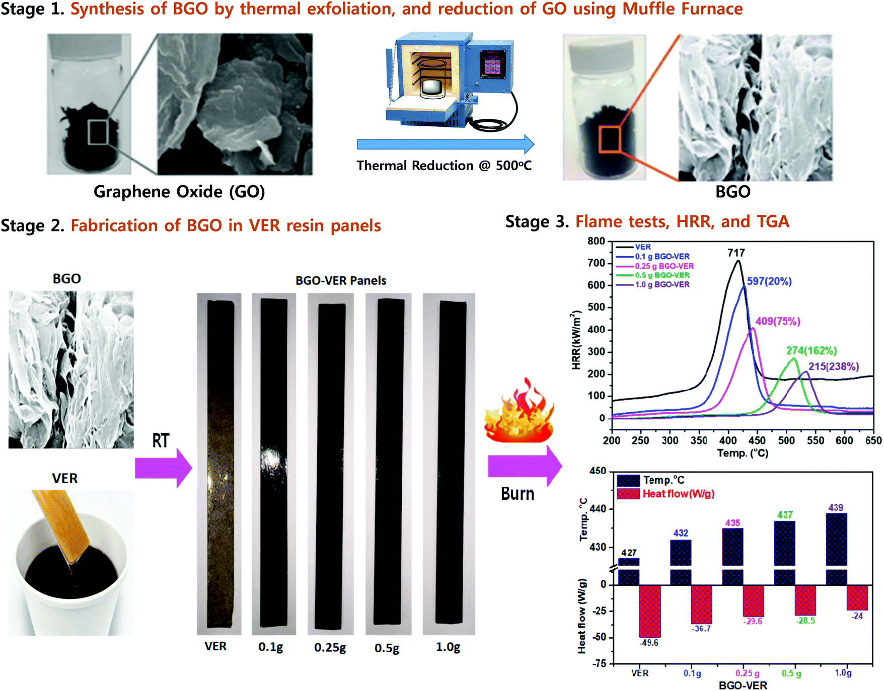 | ||
| Fig. 1 Synthesis of BGO soft nano bundles from GO (stage 1), fabrication of BGO–VER panels (stage 2), and flame, HRR, and TGA results (stage 3). | ||
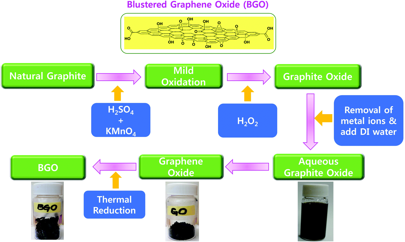 | ||
| Fig. 2 Chemical and thermal synthesis of graphene oxide (GO) and BGO soft nano bundles. | ||
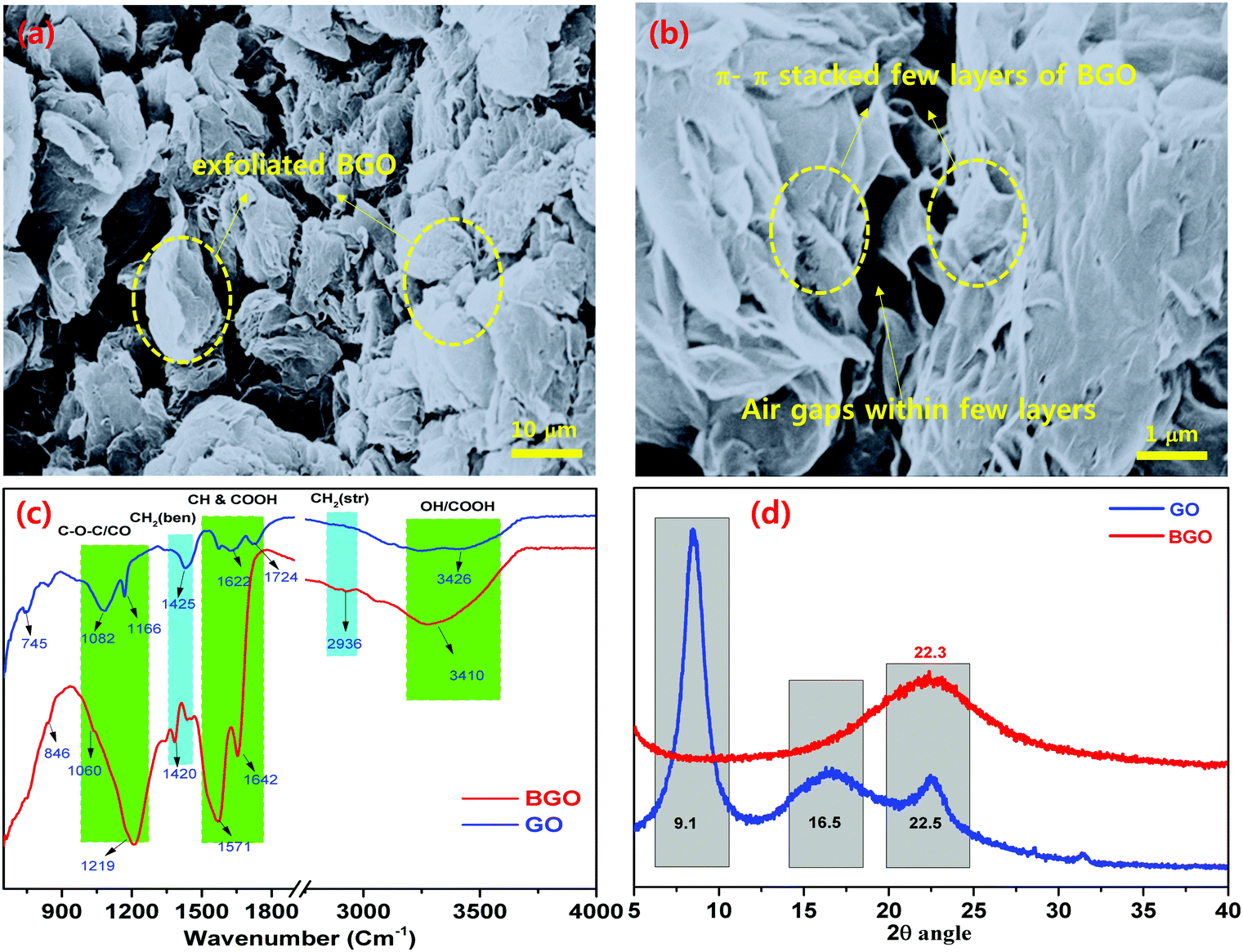 | ||
| Fig. 3 FE-SEM images of (a) π–π stacked BGO soft nano bundles with air gaps; (b) few-layered π–π stacked BGO soft nano flake bundles; and (c) FT-IR and (d) XRD of π–π stacked BGO soft nano flakes. | ||
3.2. FE-SEM, FT-IR and XRD analysis
C–), 1060 cm−1, and 846 cm−1, which match to the –OH, –CO, –C–C groups, respectively. In the case of BGO, it showed characteristic vibrational bands at 3293 cm−1 for the OH group, 2923 cm−1 for the –CH and –CH2 groups, 1653 cm−1, and 1572 cm−1 for the –CO group, and 1215 cm−1 for the –C–C groups.34 These results confirm the presence of the carboxylic acid groups adjacent to the BGO nano pockets, and these characteristic bands are shifted to 3293 cm−1 and 1572 cm−1 as broad bands.36–38
3.3. Fabrication of BGO soft nano bundles with VER resin (BGO–VE) composites
BGO is blended using a three-roll calendar blender in VER for 1 h at RT and subsequently, MEKP, hardener, and accelerator were added, respectively, Fig. 4. The final polymer mixtures were transferred into suitable molds and air-dried for 12 h at RT. Four panels with different wt% were prepared using (i.e. BGO–VER 0.1 g, 0.25 g, 0.5 g and 1.0 g), respectively. The BGO–VER composites were cut into dimensions of 20 cm × 1 cm for the horizontal flame tests.33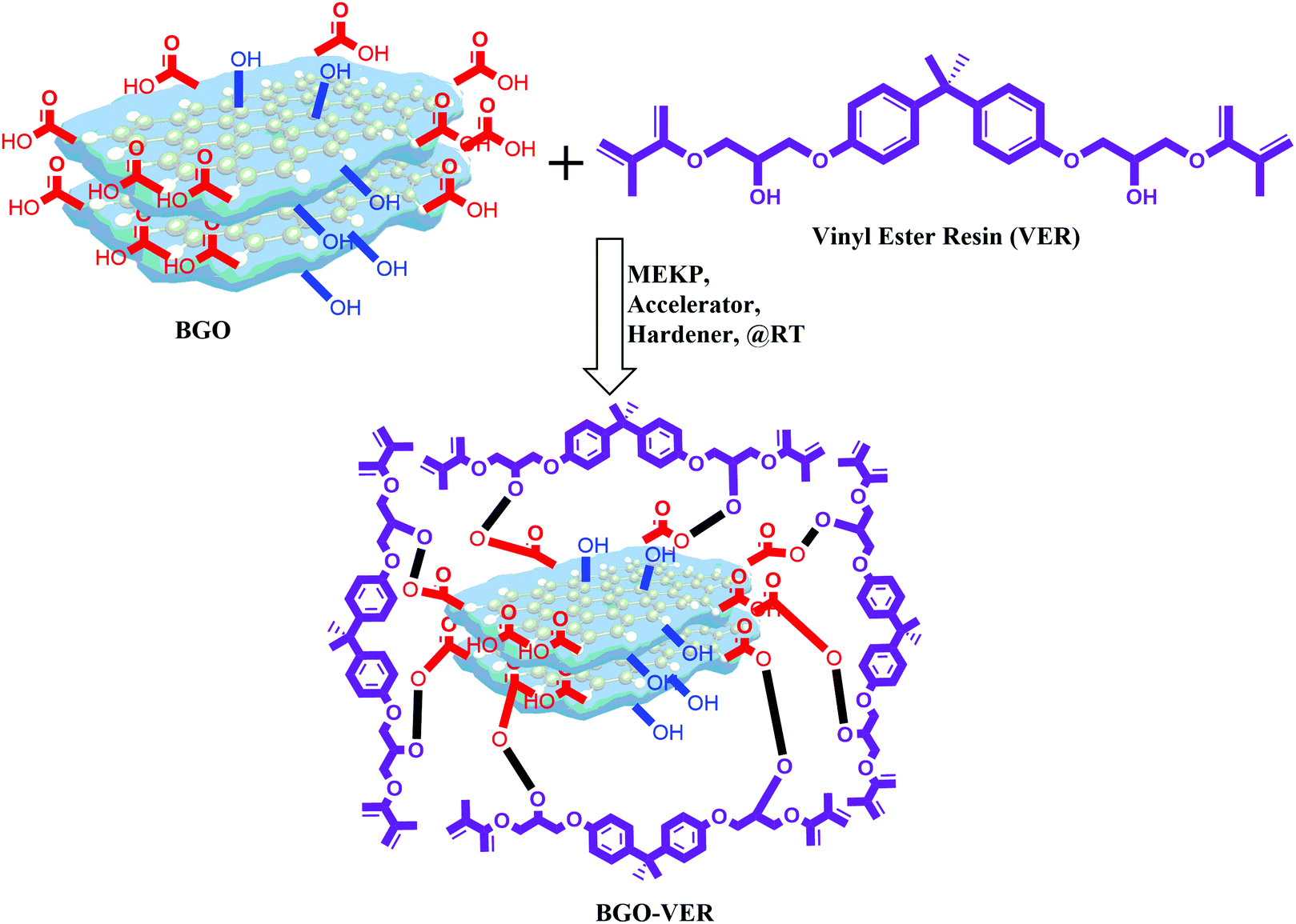 | ||
| Fig. 4 Synthesis of highly integrated BGO–VER polymer composites. | ||
3.4. Thermogravimetric analysis
Fig. 5 showed the overall TGA thermo-micrograms of the BGO–VER composites. The characteristic features of the individual composites are illustrated in comparison with BGO–VER and pure VE composites, Fig. 5a. The thermogram of the VER panel differs from that of the BGO–VER composites (i.e., 0.1 wt%, 0.25 wt%, 0.5 wt%, and 1.0 wt%). The heat degradation is started from VE at 340 °C (Tonset) to 410 °C (Tmax) and char residue at 650 °C for losses in wt% of 15, 70, and 95, respectively, owing to the disintegration by the elimination of hydroxyls, CO2, aliphatic chains such as CH2, and aromatic carbon chains. In the case of BGO, we found that the decomposition rate was only 10% due to the removal of hydroxyl and CO2 groups within the BGOs. The degradation process in the BG-VER composites is started from the first stage between 50 and 410 °C, there was a reduced weight loss of 15% that was verified due to the removal of water from moisture and CO2 groups from carboxylic acid chains. The second decomposition stage occurred from 410 °C to 470 °C and involved a weight loss of 80%, which ended by the disintegration of benzene ring systems VER basal plain chains. From 470 °C to 700 °C, the third stage of decomposition involved a weight loss of 15% from the carbon chains of BGO and VE which were converted into CO2, NO2, and NH2 gases. This change might render both hydrophobic and hydrophilic chains in BGO–VER and absorbing humidity from the environment can destroy the polymer chain and crystalline structures.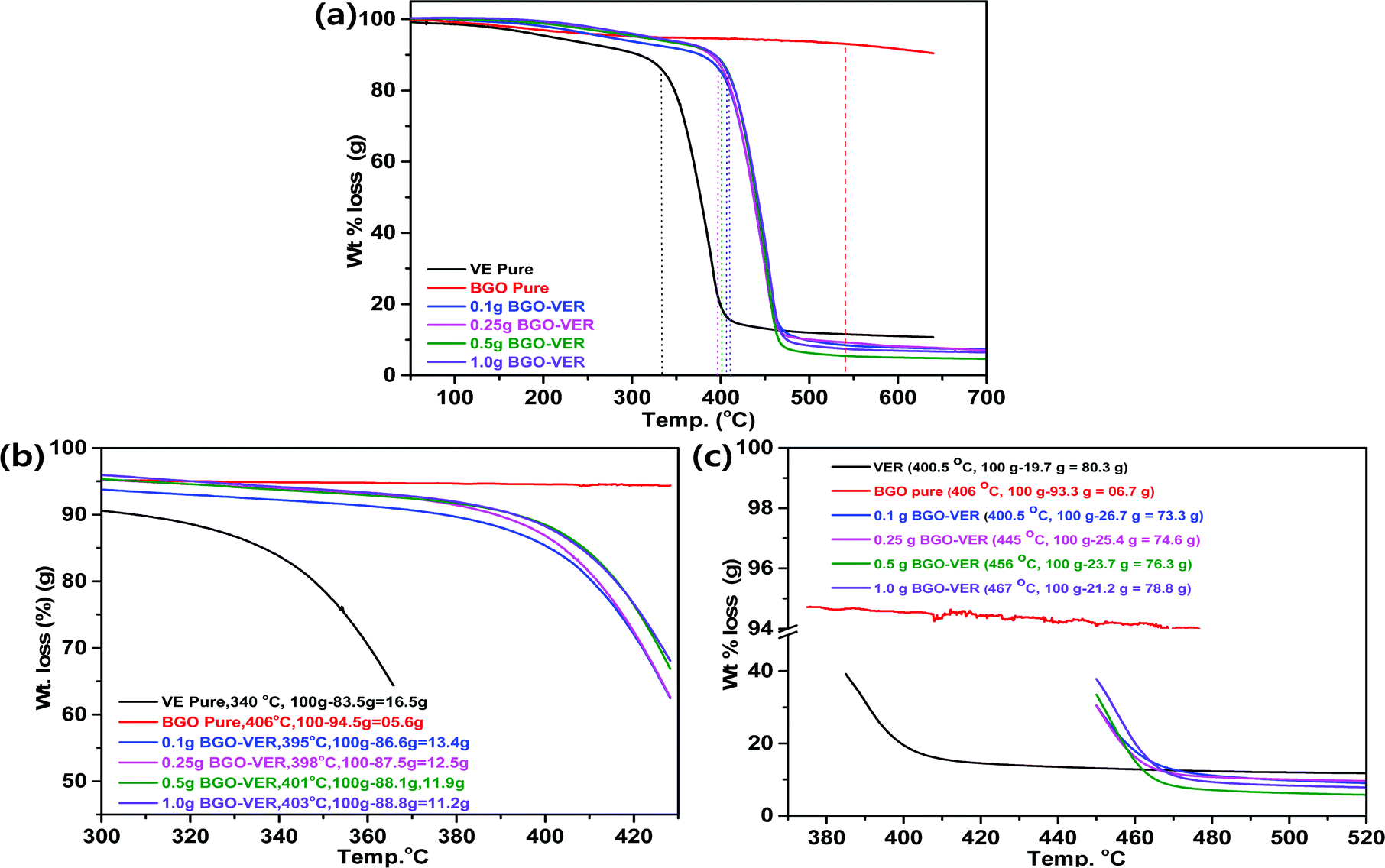 | ||
| Fig. 5 (a) TGA analyses of BGO–VER, (b) Tonset, and (c) Tmax of BGO–VER composites. | ||
Next, critical examination of the TGA thermogram is depicted in Fig. 5b and c. Fig. 5b showed the (Tonset) values, the decomposition weights of VER and BGO are 16.5 g and 5.6 g at 340 °C and 406 °C, respectively, due to removal of water molecules. The integrated composites with 0.1 g, 0.25 g, 0.5 g and 1.0 g of BGO soft nano bundles were loaded in VER and showed deposition weight losses of 13.4 g at 395 °C, 12.5 g at 398 °C, 11.9 g at 401 °C and 11.2 g at 403 °C, respectively, due to decomposition of the main aliphatic and aromatic chains of the VER.39–41 Recently, Cheng et al. reported on expandable graphite in PP composites, the initial thermal degradation temperature (T5%) of PP0 is 409 °C, and it undergoes a one-step degradation during the whole process of degradation with almost no residue char above 490 °C, which indicates the complete decomposition and flammable characteristics.42 In another case, Xu et al. reported the TGA results of neat epoxy resin (EP2) and the onset value at 294.8 °C decomposition loss of T5%![[thin space (1/6-em)]](https://www.rsc.org/images/entities/char_2009.gif) compared to their RGO doped EP composites.43 Similarly, the BGO–VER composites TGA results were little deviated compared to them, however, the polymer decomposition trend matched with our results including T(onset) data. Some deviated results have been received by our TGA experiments. Mainly, the increased thermal stability at (Tonset) by the addition of BGO sheets is responsible for the higher heat capacity of the BGO sheets and the better barrier effect of the BGO sheets. These effects retard the volatilization of the polymer decomposition products. Also, the decomposition temperature might be examined by the non-stoichiometry caused by incorporation of BGO in the VER matrix due to the homogeneous dispersion of the BGO nanofillers and the strong interfacial interaction between all the mechanisms. The increasing of char yields during the flame retardancy experiments suggests the thermal stability of BGO–VER during the TGA studies.
compared to their RGO doped EP composites.43 Similarly, the BGO–VER composites TGA results were little deviated compared to them, however, the polymer decomposition trend matched with our results including T(onset) data. Some deviated results have been received by our TGA experiments. Mainly, the increased thermal stability at (Tonset) by the addition of BGO sheets is responsible for the higher heat capacity of the BGO sheets and the better barrier effect of the BGO sheets. These effects retard the volatilization of the polymer decomposition products. Also, the decomposition temperature might be examined by the non-stoichiometry caused by incorporation of BGO in the VER matrix due to the homogeneous dispersion of the BGO nanofillers and the strong interfacial interaction between all the mechanisms. The increasing of char yields during the flame retardancy experiments suggests the thermal stability of BGO–VER during the TGA studies.
Next, the decomposition maximum (Tmax) showed weight losses of 80.3 g for VER at 400.5 °C, 6.7 g for BGO at 406 °C, 73.3 g for 0.1 g BGO–VER at 400.5 °C, 74.6 g for 0.25 g BGO–VER at 445 °C, 76.3 g for 0.5 g of BGO–VER 456 °C, and 78.8 g for 1.0 g of BGO–VER at 467 °C, respectively. The TGA trend is a three-stage decomposition with a reduction of weight loss due to the higher loading of the BGO in VER, Fig. 5c. The TGA results suggested that after doping the BGO soft nano bundles, the thermal stability of the composites significantly improved because the wt% of BGO is gradually increased, which hindered the burning intensity.40
3.5. Heat release rates (HRR) and DSC studies
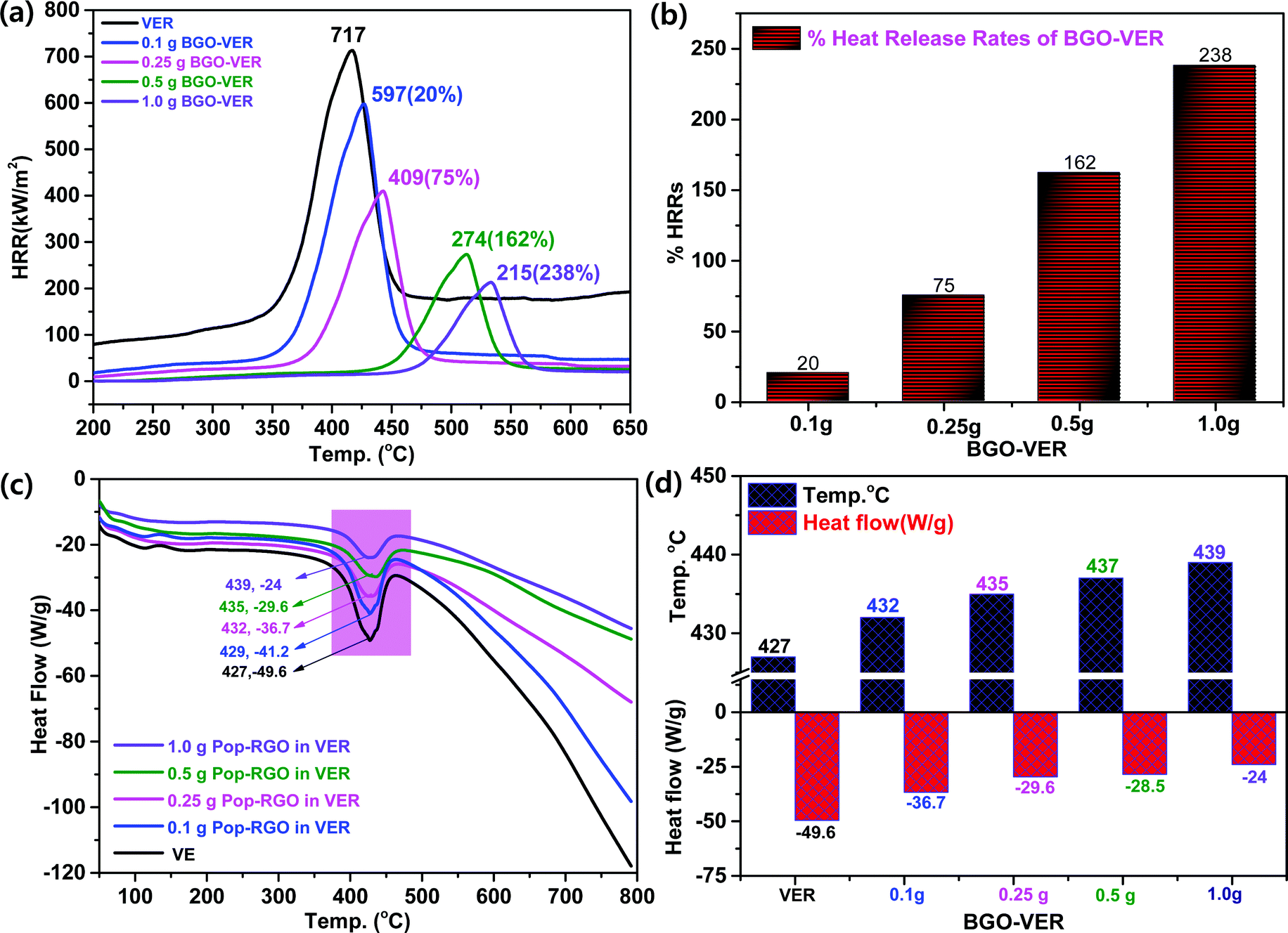
Fig. 6a showed the HRR curves of the flame-retardant BGO–VER composites, respectively. BGO–VER composites showed superior intumescent flame-retardant characteristics over the pure VER polymer composite panel. The HRRs 717 at 400 °C for pure VER, 597 at 425 °C for 0.1 g of BEG-VER, 409 at 450 °C for 0.25 g of BEG-VER, 274 at 515 °C for 0.5 g of BEG-VER and 215 at 575 °C for 1.0 g of BEG-VER, respectively. The PK-HRR, AV-HRR, and THR values were low when compared with the pristine VER. This trend indicated that the ignited neat VER went through violent burning, accompanied with a large heat release including huge exhaust gases such as CO2, CO, and NH3. Due to the higher thermal conductivity of BGO (i.e. 3000–4000 °C), the novel BGO–VER composite showed superior heat releases compared to the pure VER panels. When increasing the dopant BGO wt% in VER, the HRR was gradually reduced due to the formation of chemical bonds between CO in the VE polymer chains and improved the nucleation density of the HRR in the VER composite. Fig. 6b showed the higher % HRRs of the BGO–VER composites with respect to the pure VER composite. The % HRRs was 20% for 0.1 g of BGO–VER, 75% for 0.25 g of BGO–VER, 162% for 0.5 g of BGO–VER and 238% for 1.0 g of BGO–VER, respectively. The enhancement of the % HRRs strongly suggested that BGO plays a pivotal role in increasing the integument properties of the proposed novel BGO–VER polymer panels.
 | ||
| Fig. 6 (a) HRR, (b) % HRR, (c) DSC, and (d) a comparison of heat flow of various BGO–VER composites. | ||
Fig. 6c showed the DSC measurement that demonstrates the chemical changes within the polymer constituents when subjected to heat. The DSC curves show the melting endothermic peak of the pure VER and BGO–VER composites. In comparison to the pure VER composite, the melting endothermic peaks of the composites were shifted to a higher temperature range that strongly suggested the filling of BGO nanofillers doped in VER to improve the melting temperature (Tm) index. The decompositions in BGO–VER were observed from −41.2 at 429 °C, −36.7 at 432 °C, −29.6 at 435 °C, and −24 at 439 °C, and pure VER showed the decomposition −49.6 at 427 °C. The heat flow and decomposition rate were gradually decreased due to the loading higher wt% of BGO in VER, as shown in Fig. 6d. Besides, the carboxylic moieties at the edge plane of the BGO soft nano bundles are strongly bound through both ionic and covalent bonds to strengthen the polymer composite.44 Besides that, the BGO nanofiller played a pivotal role in enhancing the filling of the air gaps to hinder the melting range of the composite.45–48 The nonpolar functional groups in the VER showed synergistic effects along with the carbon chains when incorporated in the BGO soft nano bundles that can be glued and strongly bound to stop entering of elemental oxygen. When increasing the wt% of BGO in VER, the host VER is strongly bound through the hydrogen bonds between CO of VER chains and OH and –COOH of BGO at the basal and edge planes by increasing the nucleation density. The nucleation density was increased to reflect the crystallinity of the BGO–VER polymer system to be stable even at higher temperatures such as 429–440 °C. The results were attributed to the excellent interfacial compatibility between the BGO and VER matrix.49–51
3.6. Impact strength (IS), and horizontal burning test of BGO–VER composites
The BGO nanobundles were dispersed homogeneously in the VER matrix and enhanced the mechanical strength. To determine the mechanical strength, we determined the impact strength (IS) of all the BGO–VER panels along with the pure VER composite. The IS values were observed at 0.0128 J mm−2 for VER, 0.01317 J mm−2 for 0.1 wt% BGO–VER, 0.01377 J mm−2 for 0.25 wt% BGO–VER, 0.01433 J mm−2 for 0.5 wt% BGO–VER, and 0.01588 J mm−2 for 1 wt% BGO–VER, correspondingly. These results showed the enhancement of the impact strength up to 19.5% compared to the pure VER composite. Fig. 7a suggests the improvement of the mechanical strength of the BGO–VER composites. To estimate the intumescent flame retardancy character of the BGO–VER composites, a horizontal burning test was performed to determine the burning time and burning rates. The BGO–VER composites exhibited a higher burning time and a lower burning rate owing to the deficiency of flammability by occupying the dopant BGO. The BGO is strongly bound by a VER polymer through both hydrogen and covalent bonds. These hydrogen and covalent bonds powerfully resist the entering of oxygen into BGO–VER polymer chains.52,53 The burning time and burning rates of all BGO–VER composites are depicted in Fig. 7b. The burning time was increased from 6.29 min to 11. 2 min and the burning rate was gradually decreased from 11.93 to 6.7 from VER to BGO–VERs (i.e. BGO = 0.1 g, 0.25 g, 0.5 g, and 1.0 g), respectively. These results strongly justified the fact that the novel BGO–VER polymer composites exhibited significant intumescent flame retardancy compared to the pure VER composite.54,55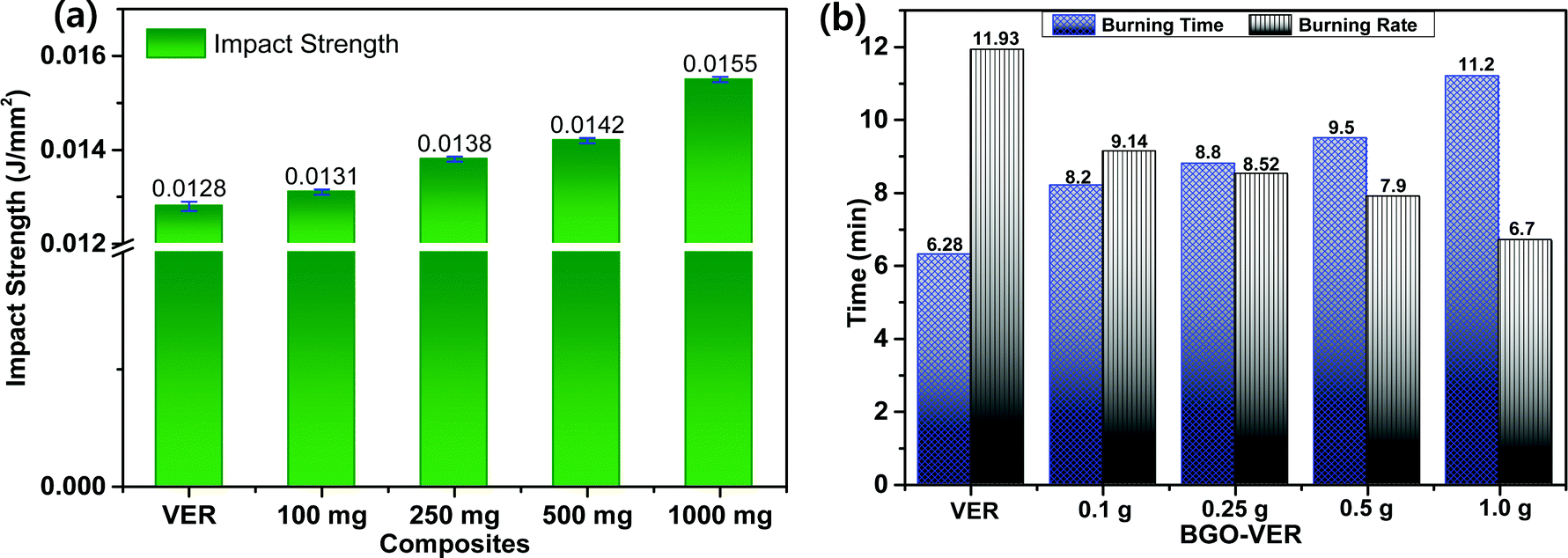 | ||
| Fig. 7 (a) Impact strength and (b) burning time and burning rates of BGO–VER panels. | ||
3.7. Digital images of the BGO–VER panels and their char residues
The distribution of BGO in the VER composite was evaluated, the morphologies of the BGO–VER composites were studied and the results are shown in Fig. 8. The homogeneous distribution of the BGO soft nano bundles was found and the intensity of BGO is increased by the darkening from pale to thick black in color of the composites from 0.1 g to 1.0 g. The intumescent flame retardancy characteristics gradually increased with BGO wt% enhancement owing to the formation of hydrogen and covalent bonds between the BGO and VER composites. Fig. 8a shows the common flame test of the VER panel. Fig. 8b–f show that the BGO–VER composites were burned and the char residues were porous and the length of the char residues was gradually increased after flame tests, it is suggested that there is formation of strong bonds between the host VER and guest BGO dopant.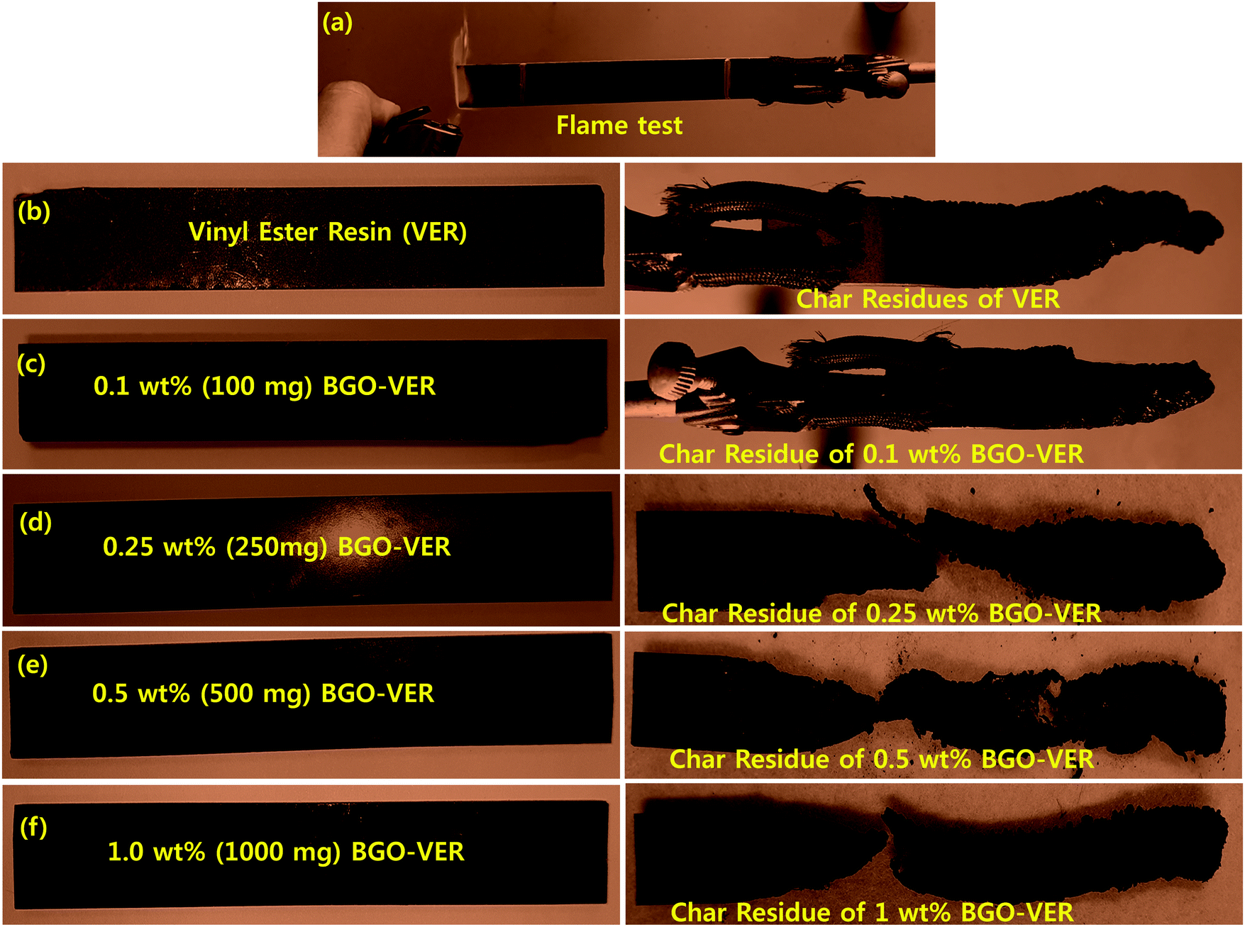 | ||
| Fig. 8 Digital images of VER and BGO–VER (i.e. 0.1 g, 0.25 g, 0.5 g, and 1.0 g) composites before and after flame tests. | ||
3.8. Char residue analysis
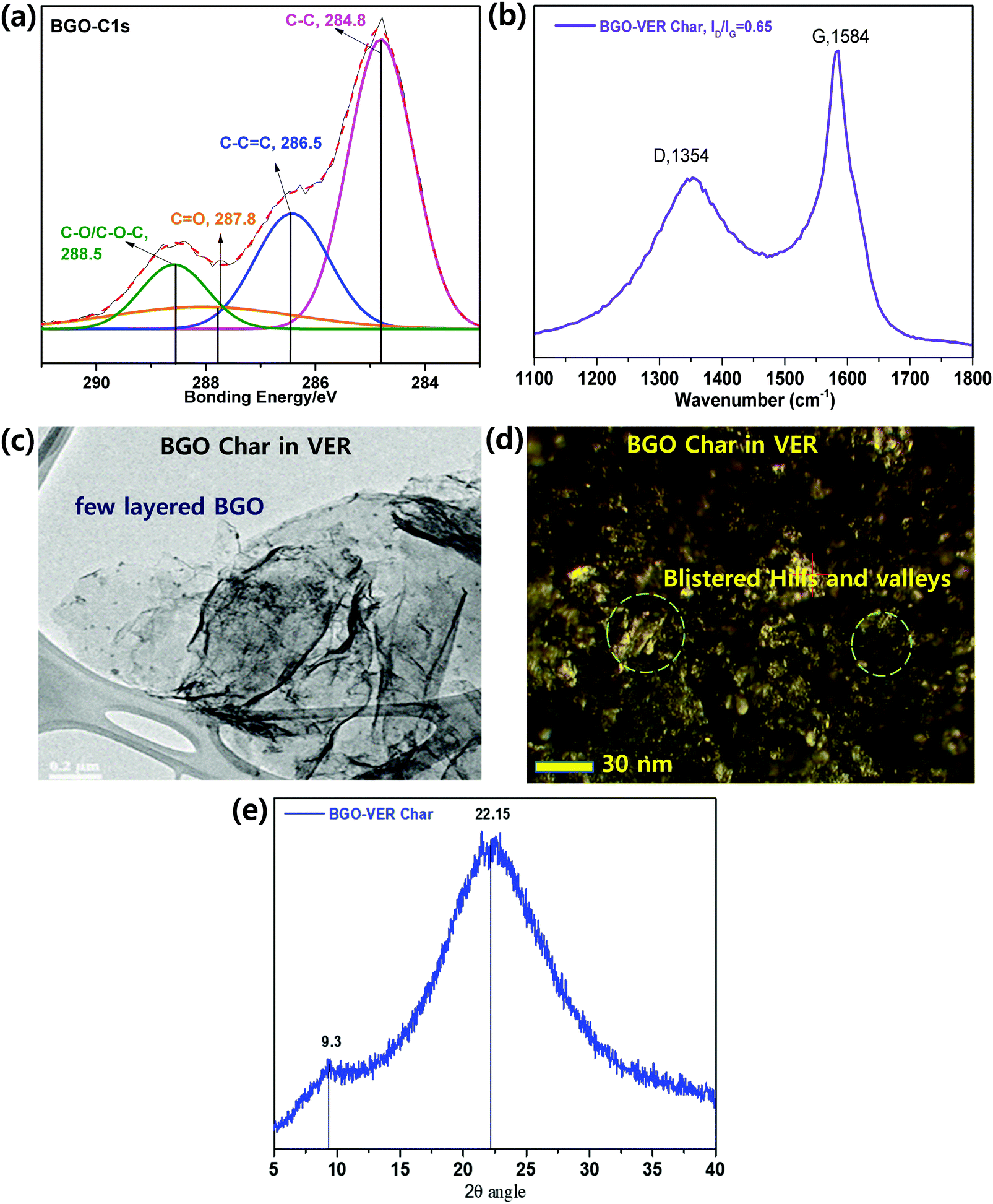
XPS. In order to define the fraction of the functional assemblies eliminated during the flame retardancy test of 1 wt% BGO–VER char residue, we performed X-ray photoelectron spectroscopy (XPS) analysis. Fig. 9a showed that the deconvoluted XPS spectra of the C1s peak discloses four peaks using binding energies of 284.60, 286.50, 287.80, and 288.50 eV, which can be attributed to C–C (single), C
C (double), CO (carbonyl), and COOH (carboxylic acid) groups, respectively.56 The C–C sp2 bond intensity is more than double that of the CC bond due to the availability of scratch on the aromatic basal carbon chain of BGO sheets. The CO (carbonyl), and COOH (carboxyl) bonds showed lower to the lowest intensities compared to the C–C bonds due to the less reduction reaction occurring during the flame retardancy test. Therefore, the C–C bond intensity showed a higher intensity compared to the other bonds. The XPS data of charred BGO in VER is in good agreement with earlier reports; they support a strong connection between the BGO and VER though chemical bonding.
 | ||
| Fig. 9 (a) XPS, (b) XRD, (c) TEM, (d) AFM, and (e) XRD analyses of 1 wt% BGO–VER char residue. | ||
Raman spectroscopy. Raman spectroscopy was employed to study the 1 wt% of BGO–VER char, as shown in Fig. 9b. The D band represents the vibration of the sp3 carbon fragments of the disordered graphitic plane, and the G band reflects the vibration of the sp2 carbon atoms on the 2D plane of the hexagonal layer lattice. Thus, the degree of graphitization char residue can be assessed by the ratio of ID and IG. The smaller the ID/IG ratios, the greater the degree of graphitization with fewer defects. The ID/IG values from 0.63 from the characteristic D band at 1354 cm−1 and G bands at 1584 cm−1, correspondingly. The lowest ID/IG in BGO–VER means the corresponding residual char has the highest degree of graphitization, demonstrating that the appropriate amount of BGO can improve the quality of residual char of VER composite. The BGO nanoflakes in the VER polymer are homogeneously dispersed which leads to particle-on-sheet, and sheet-on-sheet nanostructures. However, the higher ID/IG value of BGO–VER illustrates that more BGO could deteriorate the char residue, which is consistent with the HRR data. These structures confirmed the availability of novel BGO in VER to enhance the chemical binding to strengthen the BGO–VER panels to enhance the flame retardancy property.33
TEM. TEM is an effective method to identity the morphologies of 1 wt% of BGO bundles doped in the VER composite. BGO has a very thin two dimensional wrinkled layered like structure with folded regions. The folded region of BGO is obviously increased and some areas exhibit serious restacking due to the presence of van der Waals forces. In addition, there are numerous well-distributed particles on the layers indicating the adsorption of VER char particles. A lot of charred VER particles were loaded on the surface of the BGO layers as can be seen in Fig. 9c, showing that BGO bundles were homogeneously dispersed/loaded onto the VER polymer matrix. It is concluded that BGO bundles without any agglomeration were successfully prepared.58
AFM. Fig. 9d shows the size and morphology of 1 wt% BGO–VER char studied by AFM. During the flame test, the BGO–VER panels were popped-up and generated blister-like structures on the surface by filling of atmospheric air pockets. The surface roughness through topological morphology appeared like blisters with sizes of ∼500–600 nm and thicknesses of 0.6–1.3 nm, corresponding to the one to two layers of BGO–VER. The morphology determined that BGO bundles were homogeneously distributed within the VER matrix.58
XRD. Fig. 9e shows the X-ray diffraction (XRD) analysis of 1 wt% of BGO–VER char, showing two distinct diffraction peaks that appeared as two broad peaks at 2θ values of 22.1θ and 9.3θ that provided clear evidence of the semi-crystalline nature of BGO and GO. It reveals that along with the BGO peak, trace amounts of GO appeared within the char residue, which indicates there are significant changes present within the char network due to strong chemical interactions with GO functional groups in the host VER polymer. The XRD result of BGO char suggested the formation of sp2 carbon networks during the flame retardancy experiment.33
3.9. Flame retardancy mechanism
The flame retardant mechanism is illustrated in Fig. 10. The BGO soft nano bundles dopant could provide a flame retardant effect both in the condensed and gas phase of the BGO–VER composite. The origin of the flame retardant behavior of BGO is thought to be its ability to form a continuous, protective char layer that acts as a thermal insulator and a mass transport barrier. The heat-shielding layer slows down the escape of volatile products generated from the degrading polymer. The reductions of mass loss rate observed by TGA, the increase in char yield while polymer is undergoing pyrolysis, and the increase in the melt viscosity all suggest that for the BGO nanocomposites.54 From a mechanistic view, the VER composite completely burns and forms char residues during the flame retardancy experiment and releases huge amounts of smoke, organic volatiles, and char residues, Fig. 10a and b. However, the BGO–VER composite likely undergoes a condensed phase phenomenon due to the formation of a thermal protection barrier on the surface of the polymer composite. The key to accomplishing this sort of behavior with BGO, as with all nanocomposites, is having good dispersion of the nanofiller within the host matrix, as shown in Fig. 10c. The solvent blending and mechanical mixing techniques employed to formulate the composites presented here result in well-dispersed BGO within VER, such that the flammability of the composites was significantly decreased with the addition of BGO from 0.1 wt% to 1.0 wt%. In particular, when exposed to fire, the condensed reaction between the VER matrix and BGO derivatives results in the formation of a continuous, and compact char layer on the surface of burning, Fig. 10d. With the progression of the combustion process, a huge amount of gases resulting from the pyrolysis process could swell the sealed char layer to form a honeycombed cavity structure in the interior polymer network.26 The pyrolytic gases such as organic volatiles containing CO2, CO, CH2, O2, and H2, including considerable –OH ions, and inflammable gases could be generated during pyrolysis from carboxylic acid and methyl ester. When the amount of pyrolytic gases surpasses the storing capacity of the char layer, it could be intensively released to blow out the flame owing to the quenching effect of the BGO radicals and diluting the effect of the nonflammable gases. Based on the previous analysis, the possible fire-retardant mechanism of the BGO in the VER system could be presented as Fig. 1. VER swells to BGO flakes and forms a caterpillar-like structure due to the blowup effect of BGO, producing a wobbly char layer which cannot effectively act as a physical protective barrier. VER and BGO can also expand at a relatively low temperature, and the thermal decomposition can produce various low molecular weight intermediary molecules. At the same time, BGO can decompose into benzene rings, naphthalene, and biphenyl derivatives into carbon nano particles via rearrangement and aromatization based on C–C coupling reactions and generate graphene structures. Next, the melt products will fill into the gaps and connect the BGO flakes through the blown-up effect. At last, a compact and hard char layer with a high graphitization structure is obtained. This protection char layer containing volatile decomposed products into the flame zone. The key mechanism of BGO–VER decomposition was examined using the SEM, AFM, and TEM analyses in Section 3.8 and confirmed the BGO role to protect the BGO–VER composite panel.57,58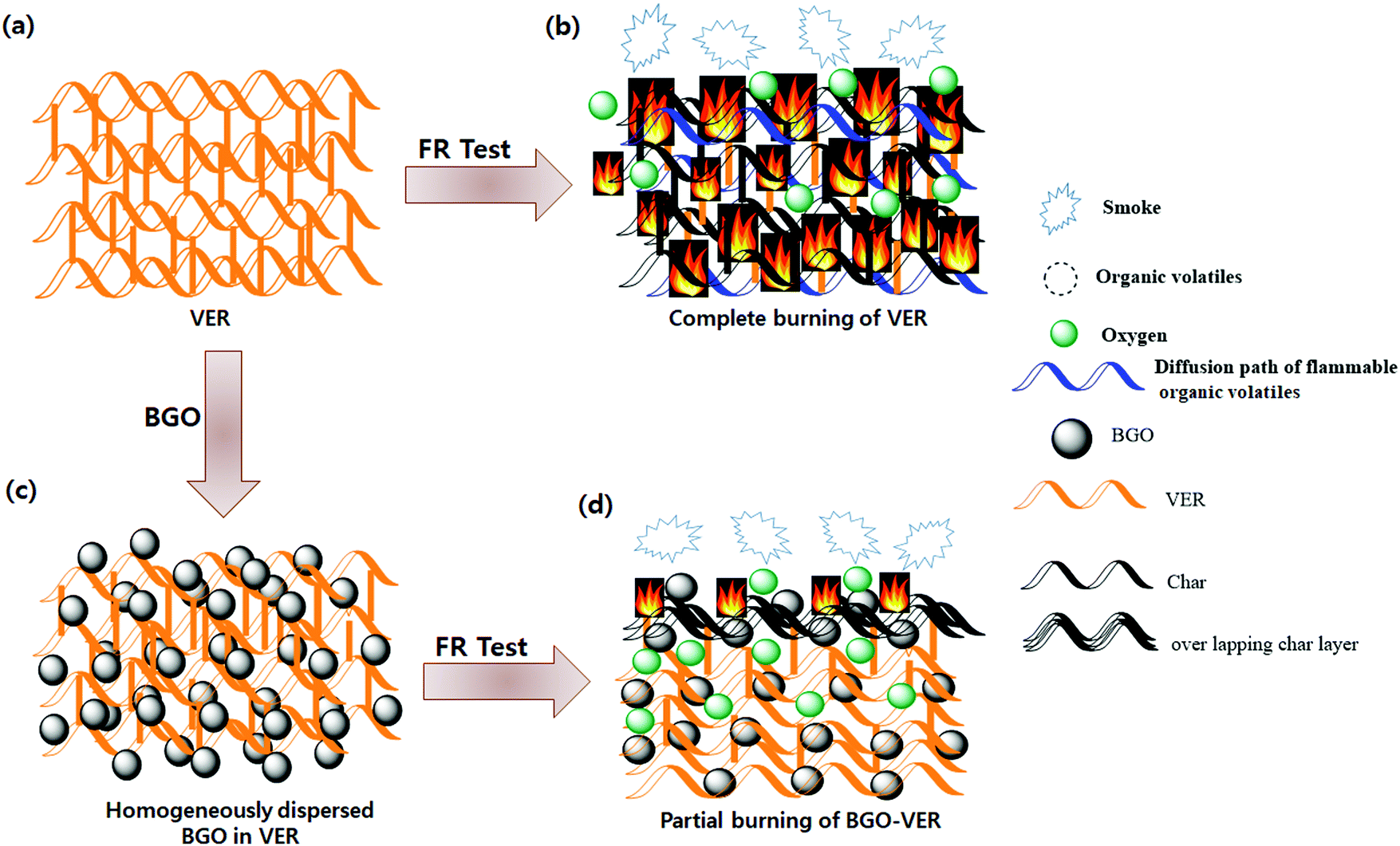 | ||
| Fig. 10 The flame retardant mechanism of the BGO–VER composites. | ||
3.10. Dendritic morphologies of the BGO–VER chars
In particular, after the flame tests, the surface morphologies of BGO–VER are illustrated in Fig. 11. The smoked BGO in the VER panel showed a dendritic porous network with huge air gaps in the polymer network. When the BGO concentration is increasing from 0.1 to 1.0 g then the densely packed dendrite network is increased, as shown in Fig. 11a–d. After the char tests, the char residues were packed strongly due to the BGO concentration being increased and reduction of the air gaps simultaneously with the strong dendrite network within the polymer. The amount of carbon residue with lattice porous networked structures with irregular holes was observed as strong evidence.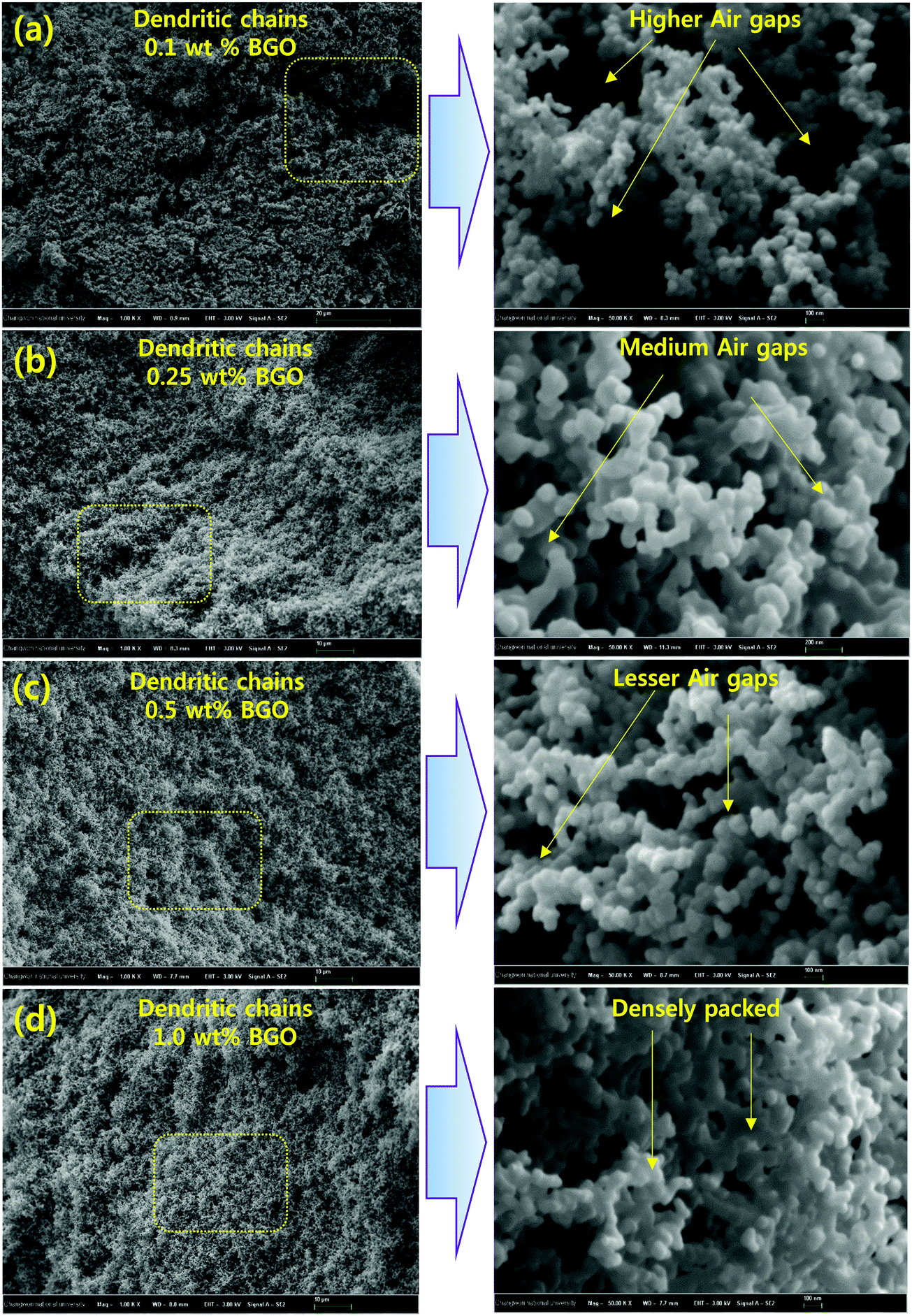 | ||
| Fig. 11 (a–d) A loose to strong porous dendritic network morphology with irregular pores in BGO–VER (i.e. 0.1 wt% to 1.0 wt%) polymer char residues. | ||
However, while increasing BGO in the VER network, the BGO soft nanobundles dopant strongly prevents the entry of oxygen molecules while the polymer panel is ablaze. Additionally, the surface morphology gradually changed with the reduction of pores, which were occupied by the BGO soft nano bundles forming the compact char layer surface. Such a dense construction is advantageous in insulating heat, hindering pyrolysis, and gas transport for the penetration of oxygen gas during the flame tests, thereby protecting the original environment from secondary combustion.41–43
4. Conclusions
We have demonstrated thermally exfoliated BGO soft nano bundles that were prepared from GO. The BGO soft nano bundles were confirmed by FT-IR, XRD, and FE-SEM. BGO is compatible with hydrophobic polymers such as vinyl ester resin (VER) at the nanoscale level to fabricate BGO–VER due to the availability of hydroxyl and carbonyl groups on the basal plane and edge centered carboxylic acid groups. We applied BGO–VER for the first time in intumescent flame retardance and achieved higher flame retardancy, thermal resistance, and heat release rates (HRRs), respectively. Besides, when increasing the BGO wt% from 0.1 wt% to 1 wt% in the VER polymer network, the TGA graphs were strongly supported the BGO dopant effect with the BGO–VER network and increased the thermal stability. Also, the heat-flow rate was suggested strongly with the dopant wt%. Besides, HRR values achieved up to 238% (1 wt%) from 20% (0.1 wt%). Incidentally, the burning time was increased up to 11.3 min, simultaneously, the burning rate was decreased to 6.7 min. The char residues showed a superior dendritic porous network that showed a BGO dopant effect with synergistic properties. Next, the regular nanoscale cavities on the porous structures facilitate the continuous gluing property between BGO and VER. The present results suggested a higher flame retardancy property that allowed the enhancement of HRR and heat-flow effects to present a high performance of next-generation flame retardant materials. Based on the present encouraging results, we are currently further exploring the next generation of high-performance flame retardant materials with economic viability.Conflicts of interest
There are no conflicts to declare.Acknowledgements
This work was supported by the National Research Foundation of Korea (NRF) grant funded by the Korea government (MSIP) No. 2018R1A6A1A03024509 and 2019R1A2C1011113.References
- S. Jaiswal and B. Gaur, Rev. Chem. Eng., 2014, 30, 567 Search PubMed.
- E. K. Can and G. R. Palmese, Eur. Polym. J., 2015, 72, 129 CrossRef CAS.
- M. Sultania, J. S. P. Rai and D. Srivastava, Eur. Polym. J., 2010, 46, 2019 CrossRef CAS.
- M. Sultania, S. B. Yadaw, J. S. P. Rai and D. Srivastava, Mater. Sci. Eng., A, 2010, 527, 4560 CrossRef.
- J. S. Arrieta, E. Richaud, B. Fayolle and F. Nizeyimana, Polym. Degrad. Stab., 2016, 129, 142 CrossRef CAS.
- A. C. Garay, L. T. Paese, J. A. Souza and S. C. Amico, Matéria, 2015, 20, 64 CAS.
- P. Li, X. Yang, Y. Yu and D. Yu, J. Appl. Polym. Sci., 2010, 92, 1124 CrossRef.
- S. Huo, V. S. Chevali and C. A. Ulven, J. Appl. Polym. Sci., 2013, 128, 3490 CrossRef CAS.
- N. Agarwal, A. Singh, I. K. Varma and V. Choudhary, J. Appl. Polym. Sci., 2008, 108, 1942 CrossRef CAS.
- S. Grishchuk, N. Castellà, A. A. Apostolov and J. J. KargerKocsis, Compos. Mater., 2011, 46, 941 CrossRef.
- A. M. Atta, S. M. El-Saeed and R. K. Farag, React. Funct. Polym., 2006, 66, 1596 CrossRef CAS.
- A. N. da Silva, G. S. Mori and J. R. M. d’Almeida, Mater. Res., 2015, 18, 121 CrossRef.
- M. Shamsuddoha, L. P. Djukic, M. M. Islam, T. Aravinthan and A. Manalo, J. Compos. Mater., 2016, 51, 1605 CrossRef.
- H. W. Cui, J. T. Jiu, S. Nagao, T. Sugahara, K. Suganuma, H. Uchida and K. A. Schroder, RSC Adv., 2014, 4, 15914 RSC.
- B. K. Kandola, J. R. Ebdon and C. Zhou, React. Funct. Polym., 2018, 129, 111 CrossRef CAS.
- U. Javaid, Z. M. Khan, M. B. Khan, M. Bassyouni, S. M. S. Abdel Hamid, M. H. Abdel-Aziz and S. W. ul Hasan, Composites, Part B, 2016, 91, 257 CrossRef CAS.
- L. Ferry, J. M. L. Cuesta, C. Chivas, G. M. W. Hoy and H. Dvir, Polym. Degrad. Stab., 2001, 74, 449 CrossRef CAS.
- H. S. Patel and B. K. Patel, Int. J. Polym. Mater., 2009, 58, 312 CrossRef CAS.
- X. S. Chen, Z. Z. Yu, W. Liu and S. Zhang, Polym. Degrad. Stab., 2009, 94, 1520 CrossRef CAS.
- C. Kaynak and N. A. Isitman, Polym. Degrad. Stab., 2011, 96, 798 CrossRef CAS.
- R. Kheyrabadi, H. Rahmani and S. H. M. Najafi, Polymer, 2017, 30, 202 Search PubMed.
- S. Y. Lu and I. Hamerton, Prog. Polym. Sci., 2002, 27, 1661 CrossRef CAS.
- L. Zang, S. Wagner, M. Ciesielski, P. Müller and M. Döring, Polym. Adv. Technol., 2011, 22, 1182 CrossRef CAS.
- Z. Cheng, D. Liao, X. Hu, W. Li, C. Xie, H. Zhang and W. Yang, Polym. Degrad. Stab., 2020, 178, 109201 CrossRef CAS.
- L. P. Gao, D. Y. Wang, Y. Z. Wang, J. S. Wang and B. Yang, Polym. Degrad. Stab., 2008, 93, 1308 CrossRef CAS.
- B. Sang, Z. W. Li, X. H. Li, L. G. Yu and Z. J. Zhang, J. Mater. Sci., 2016, 51, 8271–8295 CrossRef CAS.
- S. D. Park, S. W. Lee, S. Kang, I. C. Bang, J. H. Kim, H. S. Shin, D. W. Lee and D. W. Lee, Appl. Phys. Lett., 2010, 97, 023103 CrossRef.
- E. J. Park, S. D. Park, I. C. Bang, Y. B. Park and H. W. Park, Mater. Lett., 2012, 81, 193 CrossRef CAS.
- S. Some, Y. Kim, Y. Yoon, H. Yoo, S. Lee, Y. Park and H. Lee, Sci. Rep., 2013, 3, 1929 CrossRef.
- S. H. Liao, P. L. L. M. C. Hsiao, C. C. Teng, C. A. Wang, M. D. Ger and C. L. Chiang, Ind. Eng. Chem. Res., 2012, 51, 4573–4581 CrossRef CAS.
- H. K. Dae, W. Kim, V. Vasagar, H. Ha, S. Nazarenko and C. J. Ellison, Adv. Funct. Mater., 2018, 29, 1803172 Search PubMed.
- R. K. Cheedarala, E. Park, Y. B. Park and H. W. Park, Phys. Status Solidi A, 2015, 212, 1756–1766 CrossRef CAS.
- J. J. Jeon, R. K. Cheedarala, C. D. Kee and I. K. Oh, Adv. Funct. Mater., 2013, 23, 6007–6018 CrossRef CAS.
- R. K. Cheedarala and J. I. Song, RSC Adv., 2019, 9, 31735–31746 RSC.
- R. K. Cheedarala, J. J. Jeon, C. D. Kee and I. K. Oh, Adv. Funct. Mater., 2014, 24, 6005–6015 CrossRef CAS.
- K. Kong, R. K. Cheedarala, M. Kim, H. D. Roh, Y. B. Park and H. W. Park, Composites, Part A, 2016, 85, 103–112 CrossRef CAS.
- R. K. Cheedarala and J. I. Song, Int. J. Smart Nano Mater., 2020, 1–9 Search PubMed.
- M. N. Prabhakar, R. S. Attaur and J. I. Song, Carbohydr. Polym., 2017, 168, 201–211 CrossRef CAS.
- R. K. Cheedarala, R. Sachwani and R. K. Palakodety, Tetrahedron: Asymmetry, 2008, 19, 901–905 CrossRef.
- R. K. Cheedrala, S. Vijaya and J. W. Park, Synth. Commun., 2009, 39, 1966–1980 CrossRef.
- R. K. Cheedrala, G. H. Kim, S. Cho, J. H. Lee, J. Kim, H. K. Song, J. Y. Kim and C. Yang, J. Mater. Chem., 2011, 21, 843–850 RSC.
- Z. Cheng, D. Liao, X. Hu, W. Li, C. Xie, H. Zhang and W. Yang, Polym. Degrad. Stab., 2020, 178, 109201 CrossRef CAS.
- W. Xu, B. Zhang, X. Wang and G. Wang, RSC Adv., 2017, 7, 19662–19673 RSC.
- R. K. Cheedarala, E. J. Park, K. Kong, Y. B. Park and H. W. Park, Int. J. Heat Mass Transfer, 2016, 100, 396–406 CrossRef CAS.
- D. Huajuan, J. Sa, Y. Teng, T. Xiaoxiao, S. Yongsheng and M. Huiru, J. Appl. Polym. Sci., 2019, 47997 Search PubMed.
- S. Yang, J. Wang, S. Huo, L. Cheng and M. Wang, Polym. Degrad. Stab., 2015, 115, 63 CrossRef CAS.
- M. Gao, H. Wang, Y. Wang, T. Shen and W. J. Wu, J. Vinyl Addit. Technol., 2016, 22, 350 CrossRef CAS.
- R. K. Cheedarala, L. C. Duy and K. K. Ahn, Nano Energy, 2018, 44, 430–437 CrossRef CAS.
- R. K. Cheedarala, A. N. Parvez and K. K. Ahn, Nano Energy, 2018, 53, 362–372 CrossRef CAS.
- R. K. Cheedarala, M. Shahriar, J. H. Ahn, J. Y. Hwang and K. K. Ahn, Nano Energy, 2019, 65, 104017 CrossRef CAS.
- R. K. Cheedarala and J. I. Song, Int. J. Heat Mass Transfer, 2020, 162, 120391 CrossRef CAS.
- R. K. Cheedarala, R. Sachwani and R. K. Palakodety, Tetrahedron: Asymmetry, 2008, 19, 901–905 CrossRef CAS; J. Liu, Y. Gao, F. D. Wang and L. J. Xu, J. Mater. Sci., 2002, 37, 3085–3088 CrossRef.
- Ç. E. Emrah and A. Güngör, Polym. Degrad. Stab., 2013, 98, 927–933 CrossRef.
- L. Zhongtao, Z. Jingyan, X. Rongfei, L. Shuiping, W. Yuankun, L. Peng, W. Wenting and W. Mingbe, Chem. Eng. J., 2016, 287, 516–522 CrossRef.
- A. L. Higginbotham, J. R. Lomeda, A. B. Morgan and J. M. Tour, ACS Appl. Mater. Interfaces, 2009, 10, 2256–2261 CrossRef.
- F. Lionetto, R. L. Muñoz, C. E. González, R. M. Fernández, O. R. Fernández and A. Maffezzoli, Molecules, 2019, 12(2530), 1–22 Search PubMed.
- S. Kellici, J. Acord, J. Ball, H. S. Reehal, D. Morgan and B. Saha, RSC Adv., 2014, 4, 14858 RSC.
- P. Wang, L. Chem and H. Xiao, J. Anal. Appl. Pyrolysis, 2019, 139, 104–113 CrossRef CAS.
| This journal is © The Royal Society of Chemistry 2021 |