
 Open Access Article
 This Open Access Article is licensed under a
 Creative Commons Attribution 3.0 Unported Licence
Compatibility assessment of solid ceramic electrolytes and active materials based on thermal dilatation for the development of solid-state batteries
M.
Bertrand
a,
S.
Rousselot
a,
D.
Aymé-Perrot
b and
M.
Dollé
*a
aDépartement de Chimie, Université de Montréal, 1375 Avenue Thérèse-Lavoie-Roux, Montréal, QC H2V 0B3, Canada
bTotal SA, La Défense, 2, Pl. Jean Miller, 92078 Paris, France
First published on 22nd March 2021
Abstract
Assembling an all ceramic solid-state battery (ACSSB) using inorganic oxide electrolytes is challenging. The battery must have a continuous layered structure with a thin dense electrolyte separator and interfaces between active material (AM) and ceramic electrolytes (CE) must be optimized within the electrodes to minimize polarization. This is generally achieved using high temperature processing. Selecting suitable AM and CE materials is a complex task that requires a thorough knowledge of the electrochemical behavior of each material in addition to a deep understanding of the thermal and chemical compatibility with other components of the cell. Mismatched thermal expansion coefficients (TECs) of the various layers and materials in the device can lead to cracks during the sintering step and upon cooling that dramatically affect the battery performance. Moreover, it must be certain that no reaction occurs between active materials and electrolytes in the sintering temperature range. These are two key parameters to address for the development of all ceramic solid-state batteries. High temperature x-ray diffraction (HT-XRD) has been used to determine TECs of various well-known oxide AM and CE up to 1000 °C. It is shown that TECs of typical CEs vary between −1 × 10⁻⁵ K−1 to 4 × 10⁻⁵ K−1 but still remain more stable than that of conventional AMs, which are higher on average. On the basis of TEC, lower mismatch is found for different couples. Chemo-thermal compatibility is then investigated for couples with LiNi0.5Mn1.5O4 (LNMO) material. It is determined that mixing Li0.33La0.55TiO3 (LLTO) with LNMO might be an interesting avenue for sintering ACSSB.
Introduction
Lithium ion batteries (LIBs) are the most commonly used batteries for mobile storage because of their high energy density, long cycle life and relatively low cost. Typical LIBs contain organic liquid electrolytes.1 Despite several advantages of this type of electrolyte (high conductivity and easy formability), solid electrolytes may represent an avenue for future advances in LIB technology, including development for electric vehicles and stationary applications. Safety and energy density are among the main obstacles faced by liquid electrolytes for the most stringent LIB applications. Organic liquid electrolytes are subject to catch fire due to overheating or short-circuiting.2 Nowadays, the production of LIBs for mobile applications is well controlled and accidents are extremely rare (but not nonexistent). However, the large number of LIBs that are often packed together require higher safety standards as a result of possible chain reactions.3 Ceramic oxide electrolytes may present a solution for safer and more energy density systems because of their non-flammability and wide potential window. Inorganic oxide electrolytes have relatively good conductivities (10−5–10−3 S cm−1) at room temperature, high mechanical strength, and high chemical stability.4 However, assembling an all ceramic solid-state battery with an inorganic oxide electrolyte is challenging as it requires a deep knowledge of the electrochemical, chemical and thermal behavior of each component of the cell.2–7The battery must be a continuous layered structure of ceramics with a thin dense electrolyte separator, in order to minimize polarization.8 Preparing such batteries requires mixing solid electrolytes with active materials and conductive fillers in the electrode part to ensure optimized interfaces between active material and electrolytes. This is often achieved with oxide-based materials via high temperature processing between 600 and 1200 °C.8–13 In the electrolyte part itself, sintering at high temperature allows the ceramic grains to merge, this leads to a reduction of overall porosity. This favors the formation of an efficient lithium ion pathway between the electrolyte particles and the two composite electrodes. It can be noticed than co-sintering of CE and AM material are not the only way to prepare oxide based ASSB in the literature. For example, infiltration of AM in induced CE porosities or use of additives to allow “cold sintering” are other ways.14,15 Besides, most of the works in literature are focused on “solvent assisted” ASSB preparation that consists of the cold mixing” of CE and AM with a conducting polymer dissolved in a solvent, conductive fillers to produce composite electrode.16,17 Even though the thermal compatibility is not an issue for these systems, the chemical and electrochemical compatibility issue remain and is largely addressed.
When considering continuous layered structure of ceramics, sintering is the most critical step for material compatibility. As processing temperatures are high, the thermodynamic stability of mixed materials can be an issue and it needs to be considered. When instability is expected, the reaction kinetic may help to minimize the chemical reactivity between the electrolyte ceramic and the active material, which will then depend on the sintering technique used and the processing time at high temperature. For example, techniques like Spark Plasma sintering has been preferred due to the fast sintering which requires only few minutes to happen. The products formed are most of the time ion-insulating and electrochemically inactive.18 In that case, chemical reaction between the active material and the electrolyte should be avoided during thermal processing. Moreover, during cool down, cracks due to thermal dilatation can happen. Cracks decrease the mechanical properties of the battery and are obstacles to Li-ion displacement, so they should also be avoided.19 Because of that, thermal and chemical compatibility between ceramic electrolytes and active materials must be studied and fully understood.
However, forming multilayer ceramic devices is not new. Ceramic electrolytes are already widely used in solid oxide fuel cells (SOFC). While electroles in lithium ion batteries conduct lithium ions, unlike electrolytes in SOFC which conduct oxygen ions, similar materials can be used in both devices. The preparation of multilayer fuel cell electrolytes has been extensively researched in the past.20–24 For example, the effects of stress generated by thermal dilatation have already been addressed in SOFCs as these devices are operated at elevated temperatures. Similarly, to all ceramic battery cells, cracks within the fuel cells are highly detrimental. The primary driving force of crack formation during the fabrication of hybrid ceramics is the stress that is caused by a mismatch in the thermal expansion coefficients α (TEC) of the various layers/materials.20 TEC is defined by eqn (1):
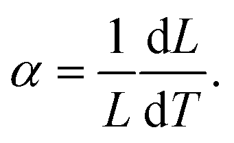 | (1) |
 | (2) |
For SOFC devices, the TEC is usually measured using dilatometry.32 In this work, high temperature X-ray diffractometry (HT-XRD) is chosen such that precise measurements can be directly related to the crystallographic structure of the sample. Moreover, with HT-XRD, the dependence of the TEC on the crystallographic axis can be assessed. It is important to take this parameter into account, because strong anisotropy could result in microcracking when the grain size exceeds a certain critical value during sintering.33 In-situ XRD also allows structural changes or parasitic reactions that occur with changing temperature to be closely followed.
The aim of this article is to suggest an effective method for the selection of compatible materials for the sintering process of all solid-state ceramic batteries. In the present paper, typical solid electrolytes and active materials for use in lithium ion batteries are studied using HT-XRD with a focus on their respective TECs. Thermal stabilities of three couples are evaluated based on the minimal mismatch of the mean TEC between the AM and the CE. These materials are tested in a classical furnace. The results presented here are intended to be used as a reference guide for battery ceramists.
Materials and method
Materials and synthesis
All CE materials were synthesized in the laboratory. Oxide CEs were prepared via solid-state processes while Li1.3Al0.3Ti1.7(PO4)3 (LATP) was produced by hydrothermal synthesis.Prior to synthesizing, La2O3 was fired at 900 °C overnight to remove carbonate due to its hygroscopic nature.
Phase pure Li1.3Al0.3Ti1.7(PO4)3 (LATP) was produced via a hydrothermal process34 using intermediate product Ti2O(PO4)2 obtained from TiO2 (99% Sigma Aldrich) stirred in an aqueous solution containing Phosphoric acid (85%) at 160 °C. Al(OH)3 (Fisher Scientific) and LiOH (98% Sigma Aldrich) were added after cooling at 80 °C. The obtained suspension was dried, ground and finally heated to 900 °C for 6 h.
Polycrystalline Li0.33La0.55TiO3 (LLTO) was prepared by solid state reaction. In order to synthetize 10 g of product, stoichiometric amounts of La2O3 and TiO2 and 10 mol% excess of Li2CO3 (to prevent lithium vaporization from occurring during thermal treatments) were mixed in isopropyl alcohol via ball milling for 24 h at 700 rpm with 12 balls of ZrO2 (10 mm diameter) in a Fritsch planetary mill Pulverisette. After solvent evaporation, the powder was calcined in an alumina crucible at 1100 °C for 1 h (rate of 20 °C min−1, heating and cooling). The resultant powder was ground using a high energy ball mill (SPEX Mill) using 3.15 g of ZrO2 ball per gram of powder with 2 wt% of stearic acid. Powder sieved below 45 μm is used in order to press a pellet (diameter = 10 mm) under a pressure of 600 MPa for 30 minutes. The pellet was sintered at 1200 °C for 5 h (heating rate of 10 °C min−1 and cooling rate of 30 °C min−1) using the powder bed technique.
Al-doped Li6.5Al0.25La2.92Zr2O12 (AL-LLZO) was prepared via a solid-state process. First, stoichiometric amounts of Al(NO3)·9H2O, ZrO2 and La2O3 and 10 mol% excess of LiOH·H2O were ground in a high energy ball mill before being degassed for 12 h at 600 °C. The degassed mixture was then milled for a second time. Part of the resulting powder was pelletized and then placed in a ZrO2 crucible using the powder bed technique at 900 °C for 10 h.
Three grades of AM layered oxides LiNixMnyCozO2 were provided by Targray, Canada: LiNi0.33Mn0.33Co0.33O2 (NMC111), LiNi0.5Mn0.3Co0.2O2 (NMC532), and LiNi0.80Co0.15Al0.05O2 (NCA). Spinel LiNi0.5Mn1.5O4 (LNMO) from Sigma Aldrich was also investigated. LiFePO4 (LFP, P2) was supplied by Johnson Matthey. LiFe0.25Mn0.75PO4 (LFMP) was synthetized by melt process.35 Fe metal (Atomet 1001HP from Rio Tinto-Quebec Metal Powder (QMP)), LiPO3 made from the dehydration of LiH2PO4 (from Sichuan Tianqi Lithium Industries Inc., China (TQC)), Fe2O3 (99%, Sigma Aldrich) and MnCO3 (99.5%, CSC) were used as precursors.
LFP was chemically delithiated into FePO4 (FP) using acetic acid and hydrogen peroxide as described by Lepage et al.36
X-ray diffraction measurements
Prior to performing any experiments, the microstructure of all materials was analyzed using a Bruker Diffractometer D8 Advance. HT-XRD were carried out at increasing temperature from 30 to 1000 °C (maximum) every 100 °C using the Bruker D8 instrument with an integrated furnace. The sample was placed in an alumina crucible. After reaching the given temperature with a heating rate of 10 °C min−1, the temperature was held for 5 minutes. Temperature uncertainty is about ±1 °C. All XRD data were collected in the 2θ range of 10/15–90° with a CuKα radiation (λ = 0.15060 nm), a step size of 0.02° and a 1 s per step rate. The applied voltage and current were 40 kV and 40 mA, respectively. XRD data was also collected at 30 °C after fast cooling. All measurements were conducted under air except for LFP and LFMP which were heated under argon to avoid oxidation of Fe2+ and Mn2+. The FePO4 measurement was also conducted under argon to avoid calcination of the carbon coating which is necessary for good electrochemical performance. Phosphate-olivine materials are heated only to 800 °C in order to avoid fusion.37 All other materials were heated to 1000 °C. Lithium evaporation is known to happen at high temperature,38–41 however, materials are exposed to temperature superior to 800 °C for no more than 4 hours (considering the heating ramp and cooling) in static atmosphere but still reach a steady temperature. Such short exposition time limits potential lithium loss during experiment.XRD of mixed material (50/50 vol%) were performed in the 2θ range of 10–80° using same instrument and parameters after ex situ heat treatment at a given temperature for 1 and 10H.
Data analysis
GSAS-II42 was used in order to extract all the cell parameters. The peak profile shape was fitted using a pseudo-Voigt profile. Rietveld refinement was performed when the CIF file was available; otherwise, Pawley refinement was done. Both methods have limited impact on the measured cell parameters. Contrary to Pawley refinement, Rietveld refinement consider the chemical structure of the material. The fitted parameters were: scale factor, sample displacement, unit cell parameters, size of the crystallites, microstrain and relative intensities. Atomic displacement parameters Uiso and the position of heavy atoms were determined when Le Bail refinement was performed. Prior to the analysis of GSAS-II, standard deviations for cell parameters were always below 1 × 10⁻³ nm. According to eqn (1), TECs are calculated using the approximation dT ≈ ΔT: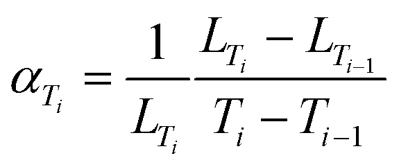 | (3) |
Tables containing resulting Rwp, cells parameters, microstrain coefficient and crystallite size for each material and temperature are available in the ESI1, Table 1.
Results and discussion
Rietveld refinement and Pawley refinement analyses are used to determine the structural changes within the materials during the heating process. Using the determined cell parameters and eqn(1), TECs as a function of temperature were calculated for CE and AM.Solid oxide electrolytes
 | ||
| Fig. 1 (a) Diffractograms of LLTO between 30 and 1000 °C and (b) fit of diffractogram of LLTO at 30 °C after cooling using Le Bail refinement. | ||
The LLTO cell parameters (Fig. 2a) at 30 °C are a = 7.753(1) Å, b = 7.803(1) and c = 7.706(1) Å. These values are in agreement with literature values.47,48 Parameters increase linearly to a = 7.818(1) Å, b = 7.864(1) and c = 7.778(1) Å at 900 °C. An order–disorder transition of La3+ ions occurs at 1000 °C where the b and c parameters tend to be closer to the a parameter with a = 7.827(1) Å, b = 7.840(1) Å and c = 7.821(1) Å.48 After cooling, the high temperature phase is preserved with a structure closer to the cubic one than to that of the initial material with a = 7.742(1) Å, b = 7.768(1) Å and c = 7.756(1) Å which demonstrates the importance of cooling rate to conserve the more conductive disordered phase49 as well as the good reversibility of the LLTO unit cell (volume of the unit cell is conserved).
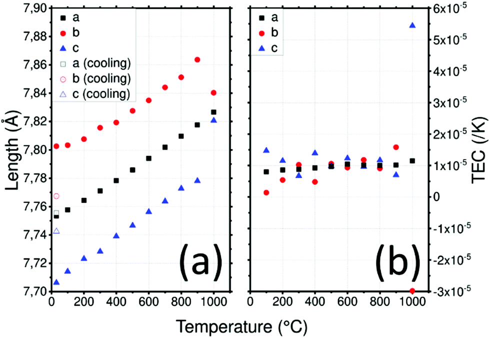 | ||
| Fig. 2 (a) Lattice parameters of LLTO depending on the temperature in air and (b) thermal expansion coefficient (TEC) as a function of temperature and the crystallographic axis of LLTO. | ||
XRD was used to determine the TEC of LLTO as shown in Fig. 2b. The TEC was found to remain relatively constant at about 1 × 10⁻⁵ K−1 until 900 °C. There is no evidence of differences between the evolution of the TEC along the a, b and c directions which is consistent with the fact that the only difference between the axes is the ordering of La atoms and the rotation of the TiO6 octahedra. At 1000 °C the order–disorder phase transition is responsible for the huge anisotropy of TECs along the b and c directions: these become −3 × 10⁻⁵ K−1 and 5.5 × 10⁻⁵ K−1 respectively.
![[3 with combining macron]](https://www.rsc.org/images/entities/char_0033_0304.gif) c space group.
c space group.
Diffractogram in the range of temperatures between 30 °C and 1000 °C and result of the fit at 30 °C using Le Bail refinement are shown in Fig. S1 (ESI1). The densification of LATP occurs at least at 700 °C.50 Small amount of LiTiPO5 are identified in the diffractometer pattern of LATP. LATP is stable up to 800 °C where intensities drop and full width at half maximum (FWHM) increase as a result of a decrease in the measured crystallite size from 250 to 120 nm. XRD analysis allows the evolution of the crystallite size to be followed when it is inferior to 200 nm, even if absolute values must be taken carefully, this evolution is significant and explained below.
LATP cell parameters in air, reported in (Fig. 3a), vary from a = 8.505(1) Å and c = 20.800(1) Å at 30 °C to 8.505(1) Å and 21.430(1) Å at 1000 °C, respectively using the hexagonal unit cell. Cell parameter a remains constant over the temperature range contrary to c which varies significantly. These cell parameters are in good agreement with the experiment conducted under vacuum by Monchak et al. up to 800 °C: this means that LATP is stable and does not release oxygen at high temperatures.51 After cooling, the cell parameters are recovered with a = 8.507(2) Å and c = 20.800(3) Å. The different evolutions of the lattice parameters with temperature are likely to lead to significant anisotropy which can be quantified by calculating the TEC.
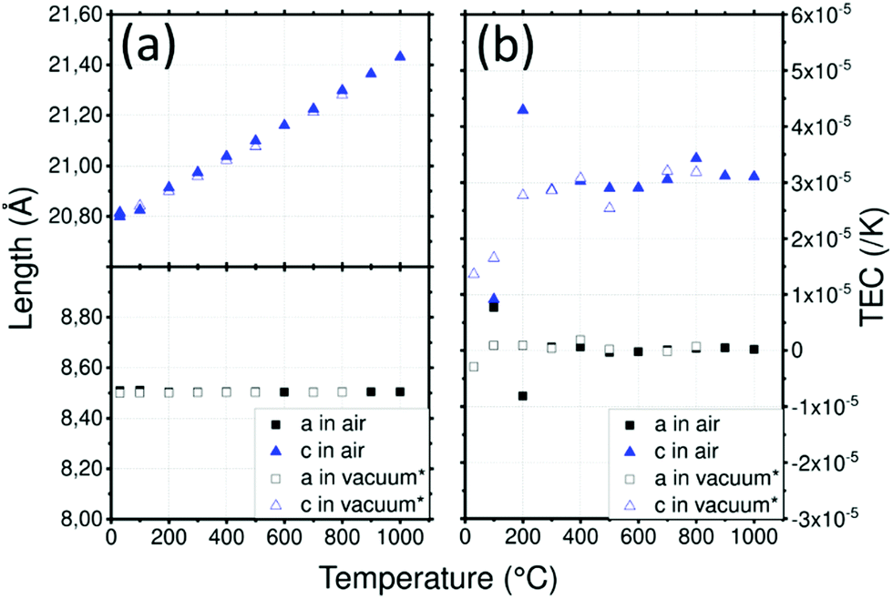 | ||
| Fig. 3 (a) Lattice parameters of LATP depending on the temperature and (b) thermal expansion coefficient (TEC) as a function of temperature and the crystallographic axis of LATP. (*) Data from Monchak et al.51 | ||
A strong anisotropy between a and c axis is visible for the TEC of the LATP material in Fig. 3b: 3.1 × 10⁻⁵ K−1 along the c axis and about 1 × 10⁻⁶ K−1 along the a axis up to 1000 °C. Critical grain size due to mismatch of the TEC was estimated to be about 1 μm.50 Because of this high anisotropy, the reduction of crystallite size observed above 800 °C can be attributed to cracks within grains leading to pulverization.50 As cracks are not suitable for ionic conductivity, the sintering of materials containing LATP should be performed carefully. Data reported by Monchak et al. were used to calculate the TEC of LATP under vacuum and are compared to the present analysis performed in air. The results from experiments performed in air or vacuum are very similar and confirm the non-influence of the atmosphere on LATP.
![[4 with combining macron]](https://www.rsc.org/images/entities/char_0034_0304.gif) 3d), Al–LLZO exhibits high ionic bulk conductivity of 10−4 to 10−3 S cm−1 at ambient temperature and a wide potential window, and it is chemically stable versus metallic lithium.52 Nevertheless, Al–LLZO has interfacial issues: it is unstable in air and it reacts with H2O and CO2, consequently Li2CO3 is easily formed on the surface, reducing the total conductivity.53 Moreover, Al–LLZO must be sintered at high temperature (about 1200 °C).54 Diffractogram in the range of temperatures between 30 °C and 1000 °C and result of the fit at 30 °C using Le Bail refinement are shown in Fig. S2 (ESI1). After synthesis, the cubic phase of Li6.5Al0.25La2.92Zr2O12 is identified with two small unknown peaks at around 2θ = 40° and 54°. A visible peak associated with La2Zr2O7 appears at 500 °C: this was attributed to a loss of lithium caused by exposure to humidity. Proton and lithium are exchanged and LiOH is formed and at higher temperature this lack of lithium causes the formation of La2Zr2O7 from Al–LLZO main phase.39,55 Nevertheless, the cubic space group of the main phase is conserved, and no other impurities are detected at higher temperatures. The structural changes occurring in the phase as a function of temperature are detailed below. As La2Zr2O7 amount is not negligeable (approximatively 12 wt% based on the ratio of main peak intensity of the two phases), diffractograms were analyzed as a two-phase mixture of Li6.5Al0.25La2.92Zr2O12 and La2Zr2O7.
3d), Al–LLZO exhibits high ionic bulk conductivity of 10−4 to 10−3 S cm−1 at ambient temperature and a wide potential window, and it is chemically stable versus metallic lithium.52 Nevertheless, Al–LLZO has interfacial issues: it is unstable in air and it reacts with H2O and CO2, consequently Li2CO3 is easily formed on the surface, reducing the total conductivity.53 Moreover, Al–LLZO must be sintered at high temperature (about 1200 °C).54 Diffractogram in the range of temperatures between 30 °C and 1000 °C and result of the fit at 30 °C using Le Bail refinement are shown in Fig. S2 (ESI1). After synthesis, the cubic phase of Li6.5Al0.25La2.92Zr2O12 is identified with two small unknown peaks at around 2θ = 40° and 54°. A visible peak associated with La2Zr2O7 appears at 500 °C: this was attributed to a loss of lithium caused by exposure to humidity. Proton and lithium are exchanged and LiOH is formed and at higher temperature this lack of lithium causes the formation of La2Zr2O7 from Al–LLZO main phase.39,55 Nevertheless, the cubic space group of the main phase is conserved, and no other impurities are detected at higher temperatures. The structural changes occurring in the phase as a function of temperature are detailed below. As La2Zr2O7 amount is not negligeable (approximatively 12 wt% based on the ratio of main peak intensity of the two phases), diffractograms were analyzed as a two-phase mixture of Li6.5Al0.25La2.92Zr2O12 and La2Zr2O7.
The Al–LLZO cell parameter presented in Fig. 4a does not vary linearly: three temperature ranges can be observed [30–200], [200–500] and [500–1000] °C. At 30 °C, the cell parameter a = 12.970(1) Å is in good agreement with the literature value.56 Then, it increases to 13.036(1) Å, 13.057(1) Å and 13.165(1) Å at 200, 500 and 1000 °C respectively. The formation of La2Zr2O7 is suspected to be responsible for this behavior: the formation of La2Zr2O7 may change the phase composition, which may also affect the cell parameters. Hubaud et al. reported the same trend for values without further indication on the formation of La2Zr2O7.19 From 500 °C to the end of the experiment, amount of La2Zr2O7 phase seems to be constant, which indicate that there is no further formation. Interestingly, cell parameter of PHASE seems to be constant around 10.90(1) Å between 500 and 1000 °C. Although La2Zr2O7 formation is irreversible and the relative intensity is not fully recovered after cooling, the cell parameter of the main phase remains almost the same as a = 12.962(1) Å.
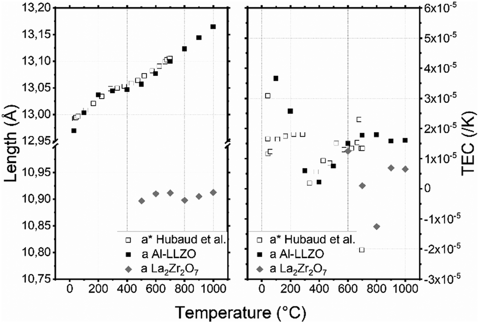 | ||
| Fig. 4 (a) Lattice parameters of AL–LLZO and La2Zr2O7 depending on the temperature in air and (b) thermal expansion coefficient (TEC) as a function of temperature and the crystallographic axis of AL–LLZO. (*) Data from Hubaud et al.19 | ||
Three specific different linear TEC evolutions associated with the three temperature ranges of Al–LLZO [30–200], [200–500] and [500–1000] °C can be observed in Fig. 4b. In the [30–200] °C range, the TEC decreases from 3.6 × 10⁻⁵ to 1.8 × 10⁻⁶ K−1 which correspond to the Al–LLZO TEC phase before pyrochlore formation. Then the TEC increases to 1.6 × 10⁻⁵ K−1 at 500 °C due to pyrochlore formation: Al–LLZO composition might be different at each temperature and so would be the TEC. Finally, after complete formation of the pyrochlore phase, the TEC of Al–LLZO stays almost constant with further increases in temperature. Mean TEC of La2Zr2O7 calculated with its cell parameters is 3 × 10⁻⁶ K−1. Robert Vassen et al. measured its TEC at 9.1 × 10⁻⁶ K−1.57 Inferior value and negative TEC measured at 800 °C might be due to incertitude as La2Zr2O7 is a minor phase and analysis has been done with only 2 peaks at low angle.
Active materials
m. Diffractogram in the range of temperatures between 30 °C and 1000 °C and result of the fit at 30 °C using Rietveld and Le Bail refinement are shown in Fig. S3–S5 (ESI1) for NMC111, NMC532 and NCA respectively. No impurities appear for NMC111 in the studied temperature range. NCA and NMC532 show no impurities until 800 °C and 1000 °C respectively. At these temperatures, the irreversible apparition of other weak intensity peaks attributed to LiAlO2 is observed. However, for the main phase, relative intensities are stable throughout the temperature range. A reaction with the alumina crucible is the main hypothesis for the formation of these impurities. Segregation of phases such as LiAlO2 in alumina doped nickel rich oxide has already been reported.58 For the three materials, the same heating treatment was performed in a classical furnace under air in an Al2O3 crucible. No impurity is found in this case. In the HT-XRD crucible, the amount of powder in contact with the crucible versus the total amount of powder was much more significant than in the classical furnace. So, products of the reaction between the alumina and the powder might be more significant than in the sample heated in the furnace crucible. Fully charged NMC and NCA materials are not tested because they have a low-temperature transition due to the permanent loss of oxygen: all NMC materials start to change into the disordered spinel form (LiMn2O4-type, Fdm) at 235 °C for NMC532, 216 °C for NMC111 and 256 °C for NCA. The phase transition occurs at a higher temperature for NCA due to it being in the rock-salt phase.59,60
NMC111 and NMC532 have very close cell parameters (Fig. 5a): a = 2.859(1) Å and c = 14.231(1) Å for NMC111 and a = 2.870(1) Å and c = 14.239(1) Å for NMC532 at 30 °C, these values are consistent with those found in literature.61,62 They increase to a = 2.923(1) Å and c = 14.231(1) Å for NMC111 and a = 2.929(1) Å and c = 14.546(1) Å for NMC532 at 1000 °C. After cooling, the NMC111 cell parameters are almost identical to the lower temperature values with a = 2.860(1) Å and c = 14.231(1) Å whereas the NMC532 cell parameters increase to a = 2.879(1) Å (+0.23%) and c = 14.262(1) Å (+0.16%). This increase in the value of the a parameter is not described in literature related to Al doping.63–67 However, loss of oxygen during heat treatment could be responsible for these differences as the same tendency was reported for LiNi0.8Mn0.1Co0.1O2 and LiNi0.6Mn0.2Co0.2O2: above 800 °C in air or nitrogen. Similar increases of a and c parameters are observed contrasting with that of samples under oxygen flow which recovered their initial cell parameters.68,69
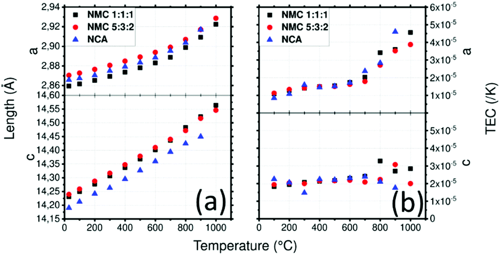 | ||
| Fig. 5 (a) Lattice parameters of NMC1:1:1, NMC5:3:2 and NCA in air depending on the temperature and (b) thermal expansion coefficient (TEC) as a function of temperature and the crystallographic axis of NMC1:1:1, NMC5:3:2 and NCA. | ||
NCA has a smaller c and a similar a lattice parameter compared to NMC materials at 30 °C with a = 2.866(1) Å and c = 14.190(1) Å which is consistent with literature70 (Fig. 5a). Lattice parameters of NCA increase to a = 2.917(1) Å and c = 14.450(1) Å at 900 °C. After cooling, cell parameter a is slightly bigger with 2.873(1) Å and c is recovered with almost no difference (14.192(1) Å).
The average TEC of NMC111 was already measured by dilatometry and was found to be about 1.2–1.3 × 10⁻⁵ K−1.71 Here, the TEC depending on the crystallographic orientation is plotted as a function of temperature in Fig. 5b and is compared to that of LiNi0.8Co0.15Al0.05O2 (NCA), which has the same structure as NMC532, in order to determine the impact on the TECs of different atomic amounts with different states of oxidation. The results are displayed in Fig. 5b. Lamellar oxides NMC111 and NMC532 show similar results: a linear increase in the TEC along the a direction from 1 × 10⁻⁵ to 2 × 10⁻⁵ K−1 at 700 °C, and then a steeper slope, increasing to 4.6 × 10⁻⁵ K−1 for NMC111 and 3.9 × 10⁻⁵ K−1 for NMC532 at 1000 °C. Interestingly, at 700 °C, impurities appear for NMC532. For NCA, the TEC along a direction increases linearly from 8 × 10⁻⁶ K−1 to 1.7 × 10⁻⁵ K−1 at 600 °C. A slope break appears, and the TEC raises to 4.6 × 10⁻⁵ K−1 at 900 °C. The TEC along the c direction increase linearly from 1.8 × 10⁻⁵ K−1 to 2.8 × 10⁻⁵ K−1 at 1000 °C for NMC111 whereas it seems to stay constant around 2 × 10⁻⁵ K−1 for NMC532. Along the c direction, the TEC is constant around 2.2 × 10⁻⁵ K−1 until 700 °C after which it decreases to 1.7 × 10⁻⁵ K−1 at 900 °C. Fig. S6 (ESI1) shows the mean TECs of NMC111, NMC532 and NCA: interestingly, All NMC-type materials have the same TEC and exhibit similar behaviour with slope breaks around 700 °C. The effect of substitution seems to change the TEC anisotropy. At the beginning of the transition, a loss of oxygen or reactivity with the crucible might be associated with the slope break.72,73 This further emphasizes the importance of sintering conditions. Sintering tools or dies and atmospheric conditions must be chosen with caution as contamination and low partial pressure of oxygen (in air, vacuum or strongly reducing graphitic environment) change the TEC and therefore may be responsible for undesired chemical reactions.
m) is a high potential positive electrode (flat discharge curve at 4.7 V).74
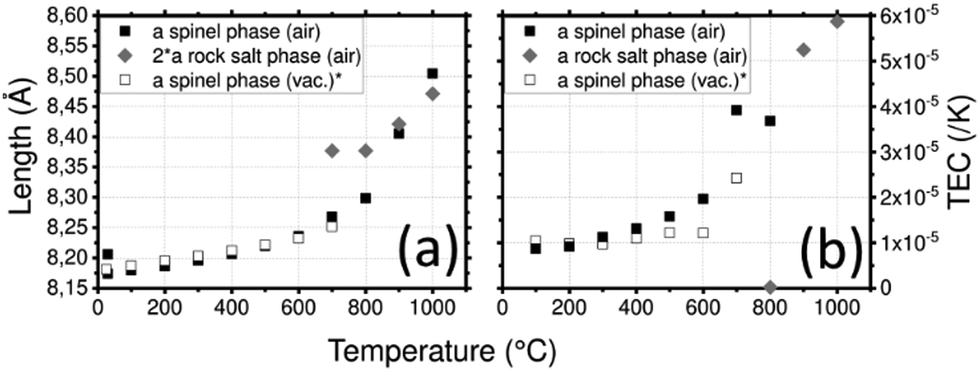
Diffractogram in the range of temperatures between 30 °C and 1000 °C and result of the fit at 30°C using Le Bail refinement are shown in Fig. S7 (ESI1). The spinel LMNO shows small impurities which have been identified as the NiMnO3 phase. The crystallographic intensities are stable until 600 °C. At 700 °C, the FWHM decreased due to increases in crystallite size from approximately 42 nm to 160 nm. A new phase is formed at the same time as is indicated by the appearance of new peaks. This reaction has been already highlighted,75 it was reported that a two-phase mixture composed of the initial spinel and the rock salt phase, space group Fmm, was formed. Oxygen loss at high temperature is responsible for the structural changes. On cooling, oxygen is regained reversibly.75 After cooling, LNMO samples have more intense peaks, and NiMnO3 impurities have disappeared which suggests that they have probably been integrated into the main phase.
LNMO parameters (Fig. 6a) vary from a = 8.174(1) Å at 30 °C to a = 8.236(1) Å at 600 °C where the spinel phase remains the major phase. At 700 °C, the rock-salt phase appears and the spinel phase tends to disappear. The mass percentage of the spinel phase progressively decreases from 100% at 600 °C to 7% at 1000 °C. This reaction might be responsible for the huge increase of the spinel phase cell parameter in this temperature range. At 1000 °C, a = 8.504(2) Å. After cooling, the spinel phase is recovered with a bigger cell parameter a = 8.206(1) Å. Integration of the NiMnO3 impurity is a plausible explanation for this increase.
 | ||
| Fig. 6 (a) Lattice parameters of LNMO depending on the temperature and (b) thermal expansion coefficient (TEC) as a function of temperature and the crystallographic axis of LNMO. (*) Calculated from data of Zeng et al.76 | ||
The spinel LMNO shows a TEC (Fig. 6b) of 1 × 10⁻⁵ K−1 at 300 °C, it increased to 2 × 10⁻⁵ K−1 at 600 °C where a slope break occurs. This is likely correlated to the loss of oxygen and to the formation of the rock salt phase. Fig. S8 (ESI1) shows the TEC of LMNO with both rock salt and spinel phases on a larger scale: the phase transition induces the huge increase of the TEC up to 1.16 × 10⁻⁴ K−1 for the spinel phase and 5.9 × 10⁻⁵ K−1 for the rock salt phase. The TEC of LNMO was measured under vacuum.76 In order to compare the TECs of these samples, they have been recalculated using eqn (3) from the given cell parameters. Surprisingly, less variations are found in the vacuum case. This is surprising as the release of oxygen under vacuum is expected to be greater than in air and is expected to result in a larger deviation in TEC. As the measurement was recorded up to 700 °C, the transition to the rock salt structure was not reported despite a break in the slope.
Cell parameters of LFP (Fig. 7a) are a = 10.321(1) Å, b = 6.001(1) Å and c = 4.693(1) Å and those of LFMP are a = 10.414(1) Å, b = 6.074(1) Å and c = 4.728(1) Å at 30 °C. The cell parameters are in good agreement with the literature81 and the difference between LFP and LFMP can be explained by the substitution of Fe by Mn which has a bigger ionic radius, 0.75 Å vs. 0.8 Å.82 In both cases, the cell parameters increase by approximately 0.11, 0.09 and 0.08 Å for a, b and c respectively. The cell parameters of FP are a = 9.818(1) Å, b = 5.790(1) Å and c = 4.781(1) Å at 30 °C and are also in good agreement with Yamada et al.83 They increase to a = 9.840(1) Å, b = 5.841(1) Å and c = 4.807(1) Å at 500 °C and follow a smoother trend than LFP and LFMP. After cooling, LFP presents almost the same a and c cell parameters while b increases slightly: a = 10.346(1) Å, b = 6.003(1) Å, c = 4.693(1) Å. LFMP presents the same cell parameters with a = 10.412(1) Å b = 6.073(1) Å and c = 4.727(1) Å.
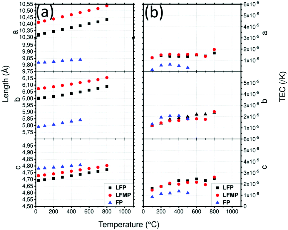 | ||
| Fig. 7 (a) Lattice parameters of LFP, LFMP and FP in argon atmosphere depending on the temperature and (b) thermal expansion coefficient (TEC) as a function of temperature and the crystallographic axis of LFP, LFMP and FP. | ||
The TEC of LFP (Fig. 7b) along the c direction presents a relatively constant increase from 1.6 × 10⁻⁵ K−1 to 2.4 × 10⁻⁵ K−1 at 600 °C, whereas that of the b direction also increases from 1.2 × 10⁻⁵ K−1 to 2.3 × 10⁻⁵ K−1. The TEC along the a direction, which is equal to 1.4 × 10⁻⁵ K−1, is almost constant throughout the temperature range. Except for LFMP at T = 800 °C, which shows a bigger increase, the TECs are very similar, meaning that Fe substitution by Mn has almost no influence on the thermal expansion of the phase. The delithiated FP material has lower a and b cell parameters and a higher c parameter which is in agreement with literature.81 Compared to LFP, FP presents lower TECs. The TEC along the c axis is the most impressive, decreasing from 1.5–2.5 × 10⁻⁵ K−1 to 0–5 × 10⁻⁶ K−1. However, the slope of the TECs begins to invert at 500 °C which might be due to the formation of Fe7(PO4)6. Fig. S6 (ESI1) shows the mean TECs of LFP, LFMP and FP: LFP and LFMP are almost identical while the TEC of the delithiated sample clearly reduces the mean.
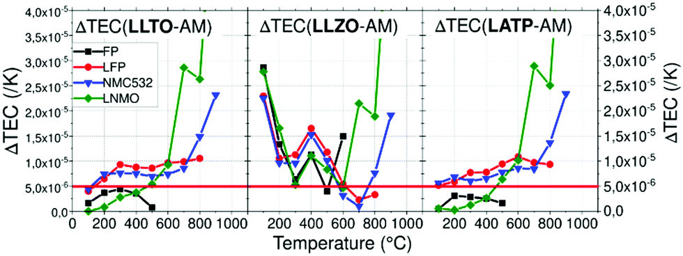 | ||
| Fig. 8 Thermal expansion coefficient difference ΔTEC between each AM and CE depending on the temperature. | ||
Using a threshold of 5.0 × 10⁻⁶ K−1, chemical stability of mixed CE/AM (CE = LLTO or LATP, AM = LNMO) was investigated by performing XRD after heat treatment. As explained above, FP in heterosite structure is not stable under air at 600 °C and FP-related impurities start to irreversibly grow even if heterosite remains the main phase at 600 °C. This maximum temperature is relatively low for allowing the efficient sintering of both LATP and LLTO ceramic electrolyte with FP. In that sense, mixture of FP with ceramic electrolytes was not further addressed. The case of LNMO is more interesting. The results are reported in Fig. 9 in the case of LATP and LLTO with LNMO. From XRD, LATP and LNMO are compatible up to 600 °C. If heat treatment is short (1H), no impurity is detected but after 10H, a new phase similar to LiMnPO4 appears with small peaks. It means that LATP and LNMO are not thermodynamically stable at this temperature but kinetic is low which allows short treatment.8 In that sense Flash sintering using Spark Plasma Sintering (SPS) might be a solution to avoid these reactions as it decreases temperature and time for sintering. Above this temperature, i.e. above the temperature of reversible splitting into spinel plus rock-salt phases, they drastically react together into LiMnPO4 and other phases.85 If the heat treatment is performed for only 1H, LLTO and LNMO show no reaction neither up to at least 900 °C, meaning both materials are compatible up to that temperature in those conditions. After longer thermal treatment (10H) at 900 °C phases similar to Li2La2Ti3O10 starts to grow. Similarly to the preceding mix, this means that LLTO and LNMO are not thermodynamically stable at 900 °C but kinetic is low which allows short thermal treatment. Though, the phase splitting of LNMO due to loss of oxygen occurring above 700 °C might not allow the sintering at higher temperature. This still needs to be clarified experimentally. As oxygen release happens at higher temperature with O2 pure atmosphere, increasing partial pressure of O2 might enhance the TEC stability of the spinel phase.86 Further experiments in O2 rich atmosphere are required to confirm our assumption. Moreover, determination of the Young's modulus of the phases might become mandatory at this point.
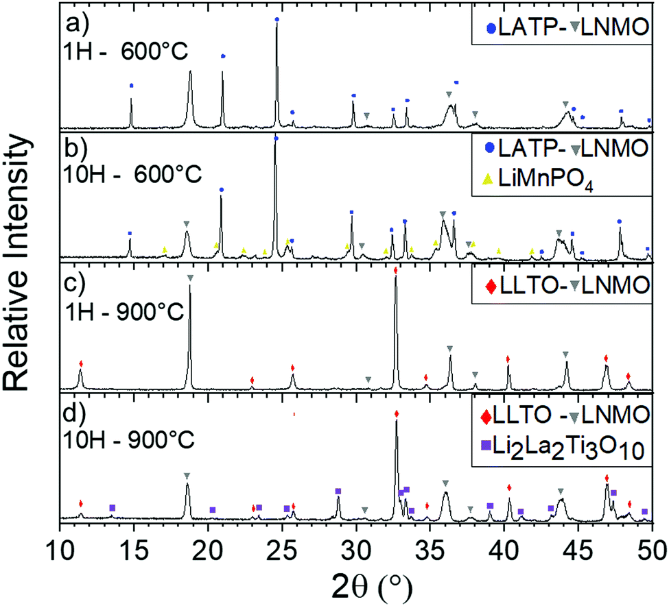 | ||
| Fig. 9 Diffractograms of mixed LATP and LNMO 50/50 vol% at 600 °C after (a) 1 h and (b) 10H and mixed LLTO and LNMO 50/50 vol% at 900 °C after (c) 1 h and (d) 10H. | ||
The thermal compatibility of active material mixed with electrolyte is discussed above without considering other components. However, the need of electronic additives such as carbon or metals and sintering aid (to favor the sintering87–89) may change these conclusions. Additives used to decrease the sintering temperature9,90,91 might act as a buffer regarding constrains with plastic deformation and allow minimal cracks during cooldown after sintering. For example use of plastic behavior sealant material in SOFC (metal or glass-ceramics) improves the resistance toward constraints as brittle fractures are more damaging than plastic deformation.92 In the same idea, use of glass-ceramic as sintering additives or metal in the electrode part may help absorbing constraints in ASSBs. Moreover, electronic additive such as carbon in electrode layers might influence the mechanical properties of the layer increasing the flexural strength or fracture toughness by suppression of crack propagation.93 On the other hand, they may also prevent ideal sintering as they can act as lubricant.94
Conclusions
In this work, we used HT-XRD in order to reference the TEC depending on crystallographic axis and temperature of various electrolyte and active materials. Minimal mismatch of TEC between materials is required to decrease stress during heat treatment because excess of stress can generate cracks that have disastrous effect on electrochemical performance. All active materials have really similar TEC, in the same range of values (1–2 × 10⁻⁵ K−1). Delithiated material FP shows smaller TECs under argon compared to LFP up to 500 °C where a non-reversible transition occurs which can be increase to 600 °C under air atmosphere. Use of delithiated active material in solid state batteries during sintering might be a way to reduce TECs mismatch but their lower thermal chemical stability is challenging regarding the densification temperature making it more complicated the assembly of charged solid state batteries for lithium metal application. Solid electrolytes have more diversified TEC and are often more constant. Nevertheless, strong anisotropy of LATP material must be taken in account when sintering as cracks occur above a critical grain size >0.2 μm. In order to highlight compatible materials with minimal mismatch of the TEC, ΔTEC between typical AM have been calculated. The lowest mismatch was found for the couples LATP/FP, LATP/LNMO, LLTO/FP and LLTO/LNMO which are below 5.0 × 10⁻⁶ K−1 until 500 °C. On top of the low TEC mismatch up to 500 °C, no thermal degradation of LLTO mixed with LNMO up to 900 °C during short treatment (1H) was reported, which is one of the highest reported to our knowledge. Thermal stability of LNMO might be increased by controlling partial pressure of O2 which might stabilize its TEC and improve thermal compatibility with LLTO at higher temperatures. Even if thermal degradation of mixes is often under the sintering temperature of CE, sintering additives might be used in order to densify composite material.We encourage others to reference TEC of other components (active materials, solid electrolytes, conductive fillers and eventually sintering aid) in order to choose and select compatible materials efficiently. Referencing the Young's modulus is another important thing to predict cracks and use more complex model depending on the architecture of the cell. Beyond that, it will be necessary to consider the stress generated by dilatation of electrodes AM during cycling as it will be critical for the lifetime of the battery.
Conflicts of interest
There are no conflicts to declare.Acknowledgements
The authors gratefully acknowledge the financial support received from the Natural Sciences and Engineering Research Council of Canada (NSERC RDCPJ 528052-18) and Total.Special thanks to Gabrielle FORAN who proofread the article to correct and improve the English.
Notes and references
- G. Zubi, R. Dufo-López, M. Carvalho and G. Pasaoglu, Renewable Sustainable Energy Rev., 2018, 89, 292–308 CrossRef.
- L. Fan, S. Wei, S. Li, Q. Li and Y. Lu, Adv. Energy Mater., 2018, 8, 1702657 CrossRef.
- S. El Khakani, J. C. Forgie, D. D. MacNeil and D. Rochefort, J. Electrochem. Soc., 2015, 162, A1432–A1438 CrossRef.
- Y. Meesala, A. Jena, H. Chang and R.-S. Liu, ACS Energy Lett., 2017, 2, 2734–2751 CrossRef.
- Y. Tian, T. Shi, W. D. Richards, J. Li, J. C. Kim, S.-H. Bo and G. Ceder, Energy. Environ. Sci., 2017, 10, 1150–1166 RSC.
- Y. Xiao, Y. Wang, S.-H. Bo, J. C. Kim, L. J. Miara and G. Ceder, Nat. Rev. Mater., 2020, 5, 105–126 CrossRef CAS.
- Y. Zhu, X. He and Y. Mo, ACS Appl. Mater. Interfaces, 2015, 7, 23685–23693 CrossRef CAS PubMed.
- G. Delaizir, V. Viallet, A. Aboulaich, R. Bouchet, L. Tortet, V. Seznec, M. Morcrette, J.-M. Tarascon, P. Rozier and M. Dollé, Adv. Funct. Mater., 2012, 22, 2140–2147 CrossRef CAS.
- F. Han, J. Yue, C. Chen, N. Zhao, X. Fan, Z. Ma, T. Gao, F. Wang, X. Guo and C. Wang, Joule, 2018, 2, 497–508 CrossRef CAS.
- K. Park, B.-C. Yu, J.-W. Jung, Y. Li, W. Zhou, H. Gao, S. Son and J. B. Goodenough, Chem. Mater., 2016, 28, 8051–8059 CrossRef CAS.
- A. Aboulaich, R. Bouchet, G. Delaizir, V. Seznec, L. Tortet, M. Morcrette, P. Rozier, J.-M. Tarascon, V. Viallet and M. Dollé, Adv. Energy Mater., 2011, 1, 179–183 CrossRef CAS.
- O. Levit, P. Xu, B. Shvartsev, G. Avioz Cohen, L. Stanciu, Y. Tsur and Y. Ein-Eli, Energy Technol., 2020, 8(12), 2000634, DOI:10.1002/ente.202000634.
- P. Xu, W. Rheinheimer, S. N. Shuvo, Z. Qi, O. Levit, H. Wang, Y. Ein-Eli and L. A. Stanciu, ChemElectroChem, 2019, 6, 4576–4585 CrossRef CAS.
- H. Shen, E. Yi, S. Heywood, D. Y. Parkinson, G. Chen, N. Tamura, S. Sofie, K. Chen and M. M. Doeff, ACS Appl. Mater. Interfaces, 2019, 12, 3494–3501 CrossRef.
- K. Nagao, M. Nose, A. Kato, A. Sakuda, A. Hayashi and M. Tatsumisago, Solid State Ionics, 2017, 308, 68–76 CrossRef CAS.
- M.-J. Kim, J.-W. Park, B. G. Kim, Y.-J. Lee, Y.-C. Ha, S.-M. Lee and K.-J. Baeg, Sci. Rep., 2020, 10, 1–11 CrossRef.
- X. Chen, W. He, L.-X. Ding, S. Wang and H. Wang, Energy. Environ. Sci., 2019, 12, 938–944 RSC.
- A. Banerjee, X. Wang, C. Fang, E. A. Wu and Y. S. Meng, Chem. Rev., 2020, 120, 6878–6933 CrossRef CAS.
- A. A. Hubaud, D. J. Schroeder, B. J. Ingram, J. S. Okasinski and J. T. Vaughey, J. Alloys Compd., 2015, 644, 804–807 CrossRef CAS.
- S. Majumdar, T. Claar and B. Flandermeyer, J. Am. Ceram. Soc., 1986, 69, 628–633 CrossRef CAS.
- N. Q. Minh and T. Takahashi, Science and Technology of Ceramic Fuel Cells, 1995, pp. 69–116 DOI:10.1016/B978-044489568-4/50005-0.
- C. S. Montross, H. Yokokawa and M. Dokiya, Br. Ceram. Trans., 2002, 101, 85–93 CrossRef CAS.
- J. Malzbender, T. Wakui and R. W. Steinbrech, Fuel Cells, 2006, 6, 123–129 CrossRef CAS.
- J. Malzbender, R. W. Steinbrech and L. Singheiser, Fuel Cells, 2009, 9, 785–793 CrossRef CAS.
- Proc. R. Soc. London, Ser. A, 1946, 186, 57–71 Search PubMed.
- C. Georgiadis, Comput. Struct., 1984, 18, 537–549 CrossRef.
- Y. Hirata, Ceram. Int., 2015, 41, 2706–2713 CrossRef CAS.
- Y. Hirata and T. Shimonosono, J. Korean Ceram. Soc., 2016, 53, 43–49 CrossRef CAS.
- K. Fischer and J. R. Seume, 2009, 6.
- J. R. Rice and M. P. Cleary, Rev. Geophys., 1976, 14, 227–241 CrossRef.
- S. Shakrawar, J. Pharoah, B. Peppley and S. Beale, ASME International Mechanical Engineering Congress and Exposition, 2010, vol. 5, pp. 983–991 Search PubMed.
- A. Selçuk, G. Merere and A. Atkinson, J. Mater. Sci., 2001, 36, 1173–1182 CrossRef.
- I. Yamai and T. Ota, J. Am. Ceram. Soc., 1993, 76, 487–491 CrossRef CAS.
- M. Holzapfel, G. Wendrich, S. Busl and G. Nuspl, US Pat., US2012/0295168A1, 2012 Search PubMed.
- E. B. Fredj, S. Rousselot, L. Danis, T. Bibienne, M. Gauthier, G. Liang and M. J. Dollé, J. Energy Storage, 2020, 27, 101116 CrossRef.
- D. Lepage, F. Sobh, C. Kuss, G. Liang and S. Schougaard, J. Power Sources, 2014, 256, 61–65 CrossRef CAS.
- M. Talebi-Esfandarani, S. Rousselot, M. Gauthier, P. Sauriol, G. Liang and M. Dollé, J. Solid State Electrochem., 2016, 20, 1821–1829 CrossRef CAS.
- C. Ban, Solid State Ionics, 2001, 140, 285–292 CrossRef CAS.
- A. Paolella, W. Zhu, G. Bertoni, S. Savoie, Z. Feng, H. Demers, V. Gariepy, G. Girard, E. Rivard and N. Delaporte, ACS Appl. Energy Mater., 2020 Search PubMed.
- K. Liu, J.-T. Ma and C.-A. Wang, J. Power Sources, 2014, 260, 109–114 CrossRef CAS.
- E. McCalla, G. H. Carey and J. R. Dahn, Solid State Ionics, 2012, 219, 11–19 CrossRef CAS.
- B. H. Toby and R. B. Von Dreele, J. Appl. Crystallogr., 2013, 46(2), 544–549 CrossRef CAS.
- Y. Inaguma and M. Nakashima, J. Power Sources, 2013, 228, 250–255 CrossRef CAS.
- F. Aguesse, J. M. López del Amo, V. Roddatis, A. Aguadero and J. A. Kilner, Adv. Mater. Interfaces, 2014, 1 CAS.
- H. Geng, A. Mei, Y. Lin and C. Nan, Mater. Sci. Eng., B, 2009, 164, 91–95 CrossRef CAS.
- Y. Inaguma, C. Liquan, M. Itoh, T. Nakamura, T. Uchida, H. Ikuta and M. Wakihara, Solid State Commun., 1993, 86, 689–693 CrossRef CAS.
- Y. Cheng, Z. Bi, A. Huq, M. Feygenson, C. Bridges, M. Paranthaman and B. J. Sumpter, J. Mater. Chem. A, 2014, 2, 2418–2426 RSC.
- O. Bohnke, H. Duroy, J.-L. Fourquet, S. Ronchetti and D. Mazza, Solid State Ionics, 2002, 149, 217–226 CrossRef CAS.
- Y. Harada, Y. Hirakoso, H. Kawai and J. Kuwano, Solid State Ionics, 1999, 121, 245–251 CrossRef CAS.
- T. Hupfer, E. C. Bucharsky, K. G. Schell, A. Senyshyn, M. Monchak, M. J. Hoffmann and H. Ehrenberg, Solid State Ionics, 2016, 288, 235–239 CrossRef CAS.
- M. Monchak, T. Hupfer, A. Senyshyn, H. Boysen, D. Chernyshov, T. Hansen, K. G. Schell, E. C. Bucharsky, M. J. Hoffmann and H. Ehrenberg, Inorg. Chem., 2016, 55, 2941–2945 CrossRef CAS.
- H. Buschmann, J. Dolle, S. Berendts, A. Kuhn, P. Bottke, M. Wilkening, P. Heitjans, A. Senyshyn, H. Ehrenberg, A. Lotnyk, V. Duppel, L. Kienle and J. Janek, Phys. Chem. Chem. Phys., 2011, 13, 19378–19392 RSC.
- S. G. Kang and D. S. Sholl, J. Phys. Chem. C, 2014, 118, 17402–17406 CrossRef CAS.
- Q. Liu, Z. Geng, C. Han, Y. Fu, S. Li, Y.-B. He, F. Kang and B. Li, J. Power Sources, 2018, 389, 120–134 CrossRef CAS.
- G. Larraz, A. Orera and M. L. Sanjuán, J. Mater. Chem. A, 2013, 1, 11419–11428 RSC.
- N. Rosenkiewitz, J. Schuhmacher, M. Bockmeyer and J. Deubener, J. Power Sources, 2015, 278, 104–108 CrossRef CAS.
- R. Vassen, X. Cao, F. Tietz, D. Basu and D. Stöver, J. Am. Ceram. Soc., 2000, 83, 2023–2028 CrossRef CAS.
- L. Croguennec, Y. Shao-Horn, A. Gloter, C. Colliex, M. Guilmard, F. Fauth and C. Delmas, Chem. Mater., 2009, 21, 1051–1059 CrossRef CAS.
- K. W. Nam, S. M. Bak, E. Hu, X. Yu, Y. Zhou, X. Wang, L. Wu, Y. Zhu, K. Y. Chung and X. Q. Yang, Adv. Funct. Mater., 2013, 23, 1047–1063 CrossRef CAS.
- S.-M. Bak, E. Hu, Y. Zhou, X. Yu, S. D. Senanayake, S.-J. Cho, K.-B. Kim, K. Y. Chung, X.-Q. Yang and K.-W. Nam, ACS Appl. Mater. Interfaces, 2014, 6, 22594–22601 CrossRef CAS.
- R. Weber, C. R. Fell, J. Dahn and S. Hy, J. Electrochem. Soc., 2017, 164, A2992–A2999 CrossRef CAS.
- C. Yang, X. Zhang, M. Huang, J. Huang and Z. Fang, ACS Appl. Mater. Interfaces, 2017, 9, 12408–12415 CrossRef CAS.
- L. Croguennec, J. Bains, J. Bréger, C. Tessier, P. Biensan, S. Levasseur and C. Delmas, J. Electrochem. Soc., 2011, 158, A664 CrossRef CAS.
- F. Zhou, X. Zhao, Z. Lu, J. Jiang and J. Dahn, Electrochem. Commun., 2008, 10, 1168–1171 CrossRef CAS.
- D. Aurbach, O. Srur-Lavi, C. Ghanty, M. Dixit, O. Haik, M. Talianker, Y. Grinblat, N. Leifer, R. Lavi and D. T. Major, J. Electrochem. Soc., 2015, 162, A1014–A1027 CrossRef CAS.
- T. E. Conry, A. Mehta, J. Cabana and M. M. Doeff, Chem. Mater., 2012, 24, 3307–3317 CrossRef CAS.
- F. Dogan, J. T. Vaughey, H. Iddir and B. Key, ACS Appl. Mater. Interfaces, 2016, 8, 16708–16717 CrossRef CAS.
- M. S. Idris and A. West, J. Electrochem. Soc., 2012, 159, A396 CrossRef CAS.
- S.-W. Lee, H. Kim, M.-S. Kim, H.-C. Youn, K. Kang, B.-W. Cho, K. C. Roh and K.-B. Kim, J. Power Sources, 2016, 315, 261–268 CrossRef CAS.
- K. D. R. Ekawati, A. P. Sholikah, C. S. Yudha, H. Widiyandari and A. Purwanto, 5th International Conference on Electric Vehicular Technology (ICEVT), IEEE, 2018, pp. 57–61 Search PubMed.
- E. J. Cheng, K. Hong, N. J. Taylor, H. Choe, J. Wolfenstine and J. Sakamoto, J. Eur. Ceram. Soc., 2017, 37, 3213–3217 CrossRef CAS.
- G. C. Kostogloudis and C. Ftikos, J. Eur. Ceram. Soc., 1999, 19, 497–505 CrossRef CAS.
- D. Marrero-López, J. Peña-Martínez, J. Ruiz-Morales, M. Martín-Sedeño and P. Núñez, J. Solid State Chem., 2009, 182, 1027–1034 CrossRef.
- Q. Zhong, A. Bonakdarpour, M. Zhang, Y. Gao and J. Dahn, J. Electrochem. Soc., 1997, 144, 205–213 CrossRef CAS.
- D. Pasero, N. Reeves, V. Pralong and A. R. West, J. Electrochem. Soc., 2008, 155(4) CrossRef CAS.
- L. Zeng, Y. Chen, W. He and L. Nong, Powder Diffr., 2008, 23, 224–227 CrossRef CAS.
- J. B. Goodenough, A. K. Padhi, K. S. Nanjundaswamy and C. Masquelier, US Pat., 5910382, 1999 Search PubMed.
- J. Hong, F. Wang, X. Wang and J. Graetz, J. Power Sources, 2011, 196, 3659–3663 CrossRef CAS.
- C. Delacourt, P. Poizot, J.-M. Tarascon and C. Masquelier, Nat. Mater., 2005, 4, 254–260 CrossRef CAS.
- S. P. Ong, A. Jain, G. Hautier, B. Kang and G. Ceder, Electrochem. Commun., 2010, 12, 427–430 CrossRef CAS.
- A. Yamada, Y. Kudo and K.-Y. Liu, J. Electrochem. Soc., 2001, 148(7), 148 CrossRef.
- R. D. Shannon, Acta Crystallogr., Sect. A: Cryst. Phys., Diffr., Theor. Gen. Crystallogr., 1976, 32, 751–767 CrossRef.
- A. Yamada, H. Koizumi, N. Sonoyama and R. Kanno, Electrochem. Solid-State Lett., 2005, 8, A409–A413 CrossRef CAS.
- N. Mahato, A. Banerjee, A. Gupta, S. Omar and K. Balani, Prog. Mater. Sci., 2015, 72, 141–337 CrossRef CAS.
- L. Miara, A. Windmüller, C.-L. Tsai, W. D. Richards, Q. Ma, S. Uhlenbruck, O. Guillon and G. Ceder, ACS Appl. Mater. Interfaces, 2016, 8, 26842–26850 CrossRef CAS.
- B. Aktekin, M. Valvo, R. I. Smith, M. H. Sørby, F. Lodi Marzano, W. Zipprich, D. Brandell, K. Edström and W. R. Brant, ACS Appl. Energy Mater., 2019, 2, 3323–3335 CrossRef CAS.
- R.-H. Shin, S. I. Son, Y. S. Han, Y. Do Kim, H.-T. Kim, S.-S. Ryu and W. Pan, Solid State Ionics, 2017, 301, 10–14 CrossRef CAS.
- T. Zhu, Y. Lin, Z. Yang, D. Su, S. Ma, M. Han and F. Chen, J. Power Sources, 2014, 261, 255–263 CrossRef CAS.
- B. Xu, B. Huang, H. Liu, H. Duan, S. Zhong and C.-A. Wang, Electrochim. Acta, 2017, 234, 1–6 CrossRef CAS.
- Z. M. Grady, K. Tsuji, A. Ndayishimiye, J. Hwan-Seo and C. A. Randall, ACS Appl. Energy Mater., 2020, 3(5), 4356–4366 CrossRef CAS.
- P. Birke, F. Salam, S. Döring and W. Weppner, Solid State Ionics, 1999, 118, 149–157 CrossRef CAS.
- J. W. Fergus, J. Power Sources, 2005, 147, 46–57 CrossRef CAS.
- K. Nakano, A. Kamiya, H. Ogawa and Y. J. Nishino, J. Ceram. Soc. Jpn., 1992, 100, 472–475 CrossRef CAS.
- D. Chung, J. Mater. Sci., 2002, 37, 1475–1489 CrossRef CAS.
| This journal is © The Royal Society of Chemistry 2021 |