
 Open Access Article
 This Open Access Article is licensed under a
 Creative Commons Attribution 3.0 Unported Licence
Bamboo-flour-filled cost-effective poly(ε-caprolactone) biocomposites: a potential contender for flexible cryo-packaging applications†
Purabi
Bhagabati
,
Deepshikha
Das
and
Vimal
Katiyar
 *
*
Department of Chemical Engineering, Indian Institute of Technology Guwahati, Guwahati, Assam 781039, India. E-mail: vkatiyar@iitg.ac.in
First published on 18th November 2020
Abstract
Polymer-based packaging waste has caused increasing environmental concern, primarily owing to its non-biodegradable characteristics. Different grades of polyethylene (PE) dominate the entire world market as major flexible packaging materials, and one of the greatest reasons is their mechanical performance under cryogenic conditions. The current situation strongly demands biodegradable packaging materials, as an alternative to conventional non-biodegradable polymers, that meet all the conditions necessary to tackle environmental pollution. Poly(ε-caprolactone) (PCL) is a hydrophobic, fossil-fuel-based biodegradable polymer that has good mechanical properties under cryogenic conditions, making it a potential rival candidate to polyethylene for flexible cryo-packaging applications. However, the development of biodegradable cryo-packaging flexible materials with comparable mechanical performance and cost advantages compared to conventional ones is still a challenge. In the present research work, the issues of high cost and the relatively inferior mechanical performance of neat PCL have been dealt with by utilizing bamboo-root flour as a cost-effective, biobased reinforcing biofiller in the PCL polymer matrix. The reinforcing behaviour of the bamboo-root flour in the PCL matrix is revealed by the increased ultimate tensile strength (UTS) and tensile toughness values of PCL5, 29% and 56%, respectively, over neat PCL. The existence of polymer–filler interactions can also be inferred from the existence of the nanofibrillar morphology and the strong nucleation and trans-crystallization phenomena that are initiated at the surface of the biofillers, as evidenced by the results from scanning electron microscopy and polarized optical microscopy images. As part of the interesting observations in the system, the PCL biocomposite, with a maximum biofiller loading (30 wt%), has shown UTS (12.4 MPa) and % elongation at break (% EB, 243%) values close to those of linear low density polyethylene (LLDPE) (UTS: ∼12.6 MPa, % EB: ∼418%). The retention of the glass transition temperature (Tg) of the PCL biocomposite filled with 30 wt% bamboo-root biofiller make it an optimum choice for flexible cryo-packaging applications.
1. Introduction
In the present scenario, environmental pollution led by conventional petrochemical-based plastics has become a great threat to the entire ecosystem of planet earth. In most cases, packaging applications are single-use and hence it is the sector responsible for the highest degree of land, water and air pollution. The increasing use of petrochemical-based plastics in packaging applications is a result of them being readily available at a relatively cheaper price, possessing a good tensile and tear strength, high oxygen and moisture barrier properties and also excellent heat-sealing properties. The increasing restrictions on these plastics in multiple countries across the world are primarily due to their poor recycling process and non-biodegradable characteristics in nature under any conditions. Over the past two decades of the century and more, biodegradable polymers have received greater research attention than bio-stable or non-biodegradable polymers, especially in packaging applications. The rising environmental awareness obtrudes the packaging industries to introduce both user-friendly, as well as environment-friendly, attributes to packaging materials. In this respect, biodegradability has emerged not only as a functional requirement, but also a mandate to the environmental attributes.Poly(ε-caprolactone) (PCL) is a petroleum based biodegradable polymer that has mostly been focused towards biomedical applications and is biodegradable under these respective conditions.1,2 Although the mechanical properties of neat PCL resemble those of conventional packaging grade linear low density polyethylene (LLDPE), certain physical properties, such as the surface hydrophobicity, glass transition temperature, gas barrier properties, and optical transparency should be taken into consideration when considering its application pertinence.3 In spite of the characteristics of PCL that can make it a strong contender for commercial LLDPE in cryo-packaging applications, few research articles are available that demonstrate its use in multiple commodity applications.4–6 Dating back to 1994, Akahori and Osawa transformed cellulosic papers into PCL coated hydrophobic papers that were biodegradable under a natural environment.7 The high cost of neat PCL is a major drawback in translating it towards commodity applications. The usual process of mitigating the cost limitation of a polymer is the addition of a low cost filler that also reinforces the polymer matrix. Filling up of the polymer with a high loading of such reinforcing particles not only reduces the overall cost of the final product, but may also contribute towards its performance, frequently referred to as the enhanced modulus. Naturally derived cellulosic or lignocellulosic materials are highly regarded as biofillers in various biodegradable polymers including PCL.8–10 Vilaplana et al. reported the acceleration of biodegradation upon the addition of these natural fibres into the PCL matrix.11 Over more than two decades, bamboo has been considered as an important source of biofiller in composite industries and different parts of bamboo plants from the waste streams of bamboo craft small scale industries may be utilized for the same purpose.12 Bamboo-root is the part of the plant that forms the majority of the waste and has little to no importance other than being used as a burning fuel in villages. In a practical sense, bamboo-roots are a cheap source of biobased biofiller that are naturally biodegradable and are readily available all across the North-East region of India. Bamboo fibres are advantageous for use as a reinforcing biofiller for several thermoplastic polymers such as polypropylene (PP) owing to their excellent mechanical, as well as thermal properties.13,14 In a similar way, bamboo-root flour is used as a biofiller as it has similar compositional characteristics to bamboo stem with the advantage of a cost benefit. Furthermore, there is negligible processing costs for the biofiller as it is not required to be refined for further use in composites. According to the previously published literature, cellulose based rice straw fibre at a 5 wt% loading resulted in sufficient reinforcement in a PCL matrix.15 In another report, wood flour acted as a better reinforcing biofiller compared to microcrystalline cellulose (MCC).8
In the present study, bamboo-root flour was chosen as a reinforcing biofiller because bamboo plants are abundant across the North-Eastern region of India. These biofillers are not chemically treated, rather they can easily be ground and sieved to obtain the necessary particle size after cleaning with a mild base, which is followed by washing with deionized water, thereby making it cheap relative to alternative biomass sources. A successful partial replacement of PCL with these low cost, untreated biofillers will essentially enhance the possibility of it being used in commodity applications, provided there are little to no adverse effects on its mechanical performance. In this investigative study, further insights into the effect of bamboo-root flour biofillers on the final physico-mechanical properties and thermal properties of the PCL biocomposites have been reported. Over-the-top modification in crystalline properties and morphology of the biocomposite allows a deeper understanding of the effect of biofillers on the PCL matrix.
2. Materials and methods
2.1. Materials
Poly(ε-caprolactone) (CAPA© 6800) was purchased from Perstorp®, United Kingdom. The number average molecular weight of the PCL was 80![[thin space (1/6-em)]](https://www.rsc.org/images/entities/char_2009.gif) 000 Da and the melt flow index (MFI) was 3 g/10 min (160 °C, 2.16 kg). The bamboo-roots of Bambusa tulda, also commonly known as Jati bamboo, are exclusively cultivated in Assam, located in the North-East region of India, these were collected from the nearby bamboo farms. LLDPE (L-Halene, grade – 73005T) (density, ρ = 0.934 g cm−3, MFI = 5.0 g/10 min) was purchased from Haldia Petrochemical Ltd (West Bengal, India).
000 Da and the melt flow index (MFI) was 3 g/10 min (160 °C, 2.16 kg). The bamboo-roots of Bambusa tulda, also commonly known as Jati bamboo, are exclusively cultivated in Assam, located in the North-East region of India, these were collected from the nearby bamboo farms. LLDPE (L-Halene, grade – 73005T) (density, ρ = 0.934 g cm−3, MFI = 5.0 g/10 min) was purchased from Haldia Petrochemical Ltd (West Bengal, India).
The next day, the swollen pieces were thoroughly washed with deionized water for neutralization. Then, the pieces were dried in a hot air oven followed by grinding and finally the flour was sieved into particles with a mesh size close to 40 μm (SECOR INDIA, Scientific Engineering Corporation, India). The polarized optical microscopy (POM) and field emission scanning electron microscopy (FESEM) images of the bamboo-root flour particles are shown in Fig. 1. Conditioning of the bamboo-root flour was performed by keeping the flour at 20 °C and 50% relative humidity (RH) in a climatic chamber before processing it with PCL in the extruder.
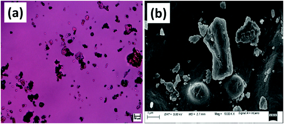 | ||
| Fig. 1 (a) A POM image and (b) an FESEM image of bamboo-root flour particles. | ||
2.2. Methods
:1. The temperature of the extruder was maintained at 100 °C and the screw speed was raised from 30 to 100 rpm as soon as the material charging was over. The recycle time was maintained as a minimum of 1 min in order to avoid any possible thermo-oxidative or hydrolytic degradation of the PCL matrix in the presence of bamboo-root flour at a temperature of 100 °C. The recycle time was optimized so as to attain sufficient melting and mixing of the biofiller with the molten PCL matrix. The melted mixture sample was placed in the injection moulding machine to make dog-bone shaped dumbbells of the samples at a cylinder temperature of 115 °C, a mould temperature of 35 °C and a 5 s holding time under the pressure range of 700–750 bar. The overall dimensions of the dumbbells were maintained at 75 × 10 × 2 mm3 while the dimensions of the gauge length region were maintained at 30 × 5 × 2 mm3 as per ASTMD638 for the tensile strength test. Five different compositions of the biocomposites, along with neat PCL, were formulated as presented in Table 1, by varying the biofiller loading in the PCL matrix. Digital images of the dog-bone sample dimensions and sample images of all PCL biocomposites are presented in Fig. 2.
| Sample designation | PCL (wt%) | Bamboo-root flour (wt%) |
|---|---|---|
| PCL0 | 100 | 0 |
| PCL5 | 95 | 5 |
| PCL10 | 90 | 10 |
| PCL15 | 85 | 15 |
| PCL20 | 80 | 20 |
| PCL30 | 70 | 30 |
 | ||
| Fig. 2 Digital images of the dog-bone-shaped dumbbell samples of the PCL0 and PCL biocomposites. | ||
The glass transition temperature (Tg), melting temperature (Tm) and crystallization temperature (Tc) of the neat PCL and its biocomposites were measured using differential scanning calorimetry (DSC) (Netzsch DSC204 F1 Phoenix, Germany). Approximately 6–10 mg of the samples were placed in the pan and heated from 30 to 100 °C at an optimized rate of 10 °C min−1 in order to eliminate the thermal history that arises in the samples during the melt processing and injection moulding. At a temperature of 100 °C, the samples were held for 3 min and then cooled from 100 to −80 °C at a 10 °C min−1 rate, held for 3 min, and the second heating cycle was commenced from −80 to 100 °C under a nitrogen gas atmosphere. The extracted data were analysed from the cooling and the second heating cycle of the DSC thermograms. The crystallographic behaviour of neat PCL and its biocomposites were studied using an X-ray diffractometer (Rigaku, TTRAX III 18 kW, Japan) equipped with Cu-Kα radiation (λ = 1.5406 Å). The crystallinity of the neat PCL and its biocomposites was carried out at a 50 kV functioning voltage in the grazing incident mode operated at 100 mA. Samples were mounted on the sample holder and heated at 2θ range from 2–30 °C with a scan rate of 0.5 °C min−1.
3. Results and discussion
3.1. Mechanical property studies
The mechanical performance of PCL0 and its biocomposites with varying concentrations of bamboo-root flour requires significant investigation, as one of the primary aims of the work is to reduce the cost of the product without compromising its mechanical strength. The representative stress–strain plot of PCL0 and the biocomposites of bamboo-root flour are shown in Fig. 3a; and the data extracted from the plot are presented in the form of a bar diagram in Fig. 3b–e. From the stress–strain graph, it is evident that PCL0 and its biocomposites show typical thermoplastic behaviour, which consists of a linear elastic region resulting from the Young's modulus of the material; which is followed by slow deviation from the linear behaviour to plastic flow known as yielding.16,17 In this region, we see the yield strength of the material, which is also the maximum tensile strength of PCL0. Therefore, up to the maximum yield strength of the material, we find the linear elastic region. Slow necking owing to a non-uniform distribution of the applied strain across the gage length of the specimen started to take place immediately after the yielding, which leads to sharp drop in the stress against % strain and is followed by a steady plastic flow at the molecular level until final breakage.16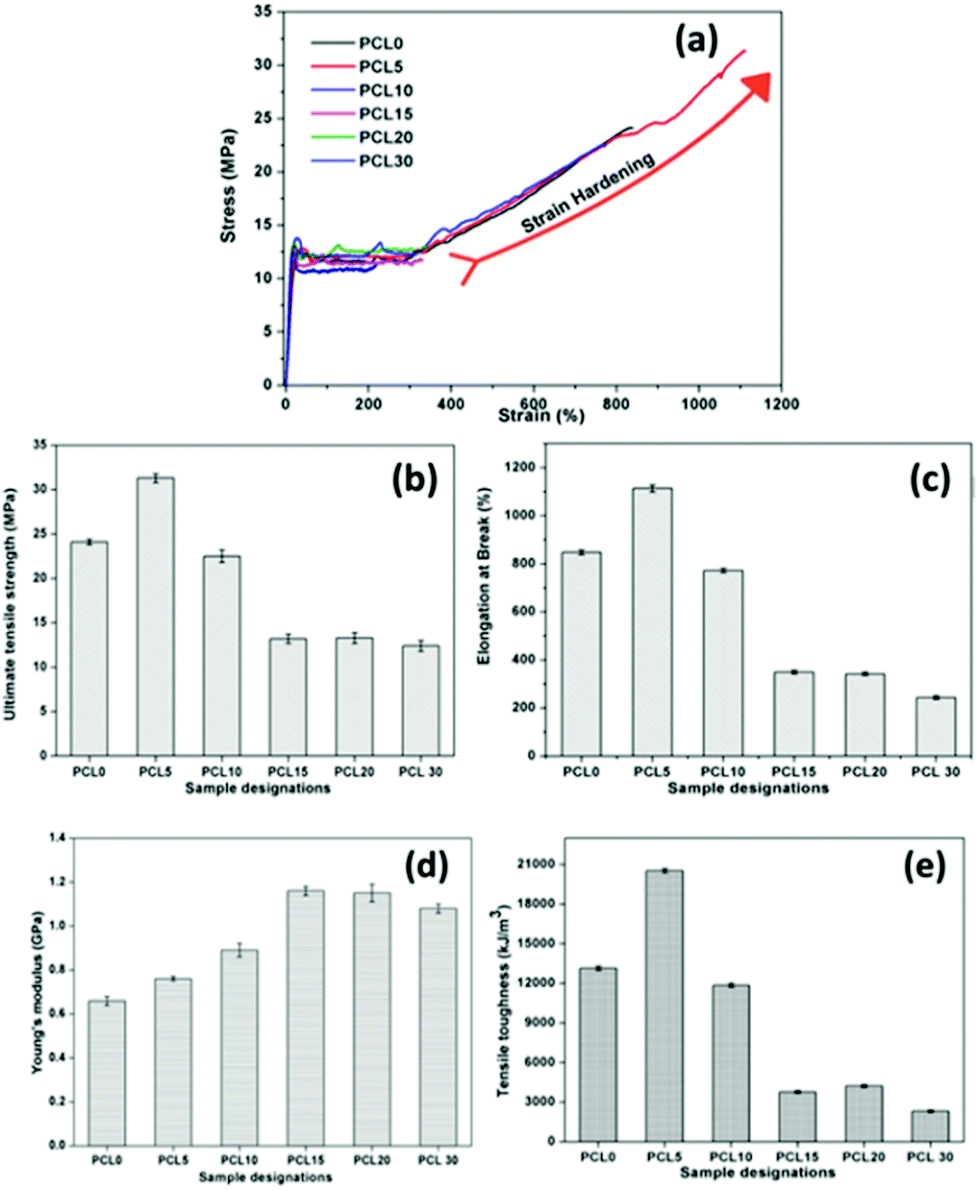 | ||
| Fig. 3 (a) Representative stress–strain plots, and bar diagrams of the (b) UTS (MPa), (c) % EB, (d) Young's modulus, and (e) tensile toughness of neat PCL (PCL0) and its biocomposites. | ||
In the case of the PCL0 sample, the steady plastic deformation after the necking continued up to 270% elongation and then it underwent rapid strain induced crystallization (strain hardening) that continued until its breakage at 830% elongation. After the plastic deformation of the sample in its necked region, higher engineering stress is required to stretch it further. The strain hardening phenomenon in certain semi-crystalline polymers is the result of the development of the strengthened fibrillar morphology that is axially oriented along the drawing force. The breaking load of this morphologically modified region of the material is much higher than the stress required to form necking in the morphologically untransformed region that is situated away from the neck region. Typically, the semi-crystalline polymer contains “spherulites” that consist of crystalline lamellas radially arranged outwards in the spherical domain. In the case of PCL0 at a strain of 270%, these spherulites become deformed along the drawing direction. A further increase in the strain causes breaking of the spherical structure of the spherulites and allows the lamellae to rearrange themselves along the direction of the stretching, resulting in a fibrillar microstructure. Nitta and Yamaguchi developed the ideal spherulitic model in which the crystalline lamellae resemble rigid platelets that are interconnected with each other by amorphous floating and tie chains.18 According to their theoretical model, the stress–strain curves of the polymers are independent of the spherulite size, but are highly dependent upon the crystalline lamellae or nodule thickness and interlamellar (internodule) distances.19
In semicrystalline polymers the crystalline regions play a tremendous role in the mechanical properties, and the mechanism of plastic deformation of such polymers differ greatly owing to the presence of entangled floating chains of the amorphous phase. The tensile test of the semicrystalline PCL and its biocomposites was performed at a temperature well above the Tg. Under such circumstances, the global deformation behaviour of the semicrystalline PCL samples may be regarded as the stretching of two different interpenetrated networks of interlocked crystalline lamellae and the entangled amorphous phase. Initially, the application of tensile load leads to deformation, followed by alignment of the amorphous tie chains, which transmits the stress to the nodules. As previously reported in the literature, such deformation in the initial process involves slippage within the lamellae and intralamellar mosaic block slippage, and the crystalline nodules remain stable over this process.20 At a larger strain, the crystalline blocks become unstable and undergo stress-induced melting and recrystallization, which leads to development of newly oriented crystallites in the form of fibrils. Such fibrillar morphology was observed in the FESEM images and detailed investigation of the morphology of the tensile fracture surfaces of neat PCL and its biocomposites will be discussed thoroughly in a later section. The lamellae in the fibrillar morphology of the semicrystalline PCL has dominantly lined-up along the load-bearing axis, which are interconnected with each other through amorphous tie up polymer chains and demonstrate a markedly higher mechanical strength and stiffness. A similar sigmoidal stress–strain curve with a strain hardening effect is observed in the case of the PCL5 and PCL10 biocomposites.20
In the case of samples that exhibit the strain hardening phenomenon, for example PCL0, PCL5 and PCL10, the UTS corresponds to the stress at the fracture point, while in samples that do not possess a strain hardening effect, the UTS corresponds to the stress at the maximum yield point (Table 2). To our surprise, a higher degree of strain hardening was found to occur in PCL5, associated with a % elongation at fracture of 1113%. In addition, the qualitative observation from the slope of the respective stress–strain curves indicates the rate of strain hardening of PCL5 is far higher than that of PCL0. In PCL5, the higher strain hardening rate at increased strain causes a sharp upturn in the stress–strain plot. Such melioration in the mechanical properties of the PCL biocomposites with a concentration of 5 wt% of bamboo-root flour as filler represents the effective reinforcement of the biofillers in the PCL matrix. As shown in Fig. 3, close maintenance of the mechanical properties at a higher concentration of biofiller, such as 10 wt%, with PCL0 was possible, which could possibly be explained by the combined effect of two opposite factors; filler reinforcement and agglomeration. A further increase in the biofiller concentration up to 20 wt% (both PCL15 and PCL20) showed a saturated value in all the parameters of the mechanical properties, as presented in Fig. 3b–e. At a 30 wt% concentration of biofillers in PCL30, the UTM and % EB reduced by 6% and 28%, respectively over PCL15 and PCL20. The dominant negative impact of filler agglomeration over the reinforcement in the PCL matrix at a high concentration is the major cause of the reduced mechanical properties of the PCL biocomposites in PCL30. In contrast, in PCL10 the strain hardening process started at 320% elongation and continued until its fracture point of 772% of strain at a relatively lower rate of strain hardening compared to PCL0 and PCL5. Strain hardening is a phenomenon that provides added benefit to the semi-crystalline polymer over its load bearing applications, such as in carrier bags. The stress–strain graph of LLDPE is shown in Fig. S1 in the ESI,† and the data obtained from the graph is presented in the figure itself. Here, the UTS value was 12.6 MPa, the % EB is 418%, and the tensile toughness is 4282 kJ m−3. The PCL0, PCL5 and PCL10 are superior to neat LLDPE as the percentage improvement in UTS, % EB and tensile toughness of PCL0 (91.2%, 102% and 206%), PCL5 (148%, 166% and 379%) and PCL10 (78%, 84% and 177%) are very high. Moreover, the strain hardening phenomenon is absent in LLDPE. Thus, in terms of the mechanical properties, both the neat PCL and its biocomposites, that is PCL5 and PCL10, are superior to LLDPE. Although substitution with 5 wt% of bamboo-root flour in PCL shows a synergistic effect upon its mechanical properties induced by reinforcement, a 10 wt% of filler did not cause any deterioration in the properties compared to neat PCL.
| Sample designation | % elongation for the initiation of strain hardening | Maximum yield stress (MPa) |
|---|---|---|
| a The rate of strain hardening is calculated from the slope of the linear fitted plot in the respective region. | ||
| PCL0 | 270% ± 10 | 12.4 ± 0.4 |
| PCL5 | 300% ± 15 | 12.8 ± 0.4 |
| PCL10 | 320% ± 9 | 13.8 ± 0.5 |
| PCL15 | NA | 13.2 ± 0.2 |
| PCL20 | NA | 13.2 ± 0.2 |
| PCL30 | NA | 12.4 ± 0.3 |
However, an increase in the filler loading in the system caused changes in the behaviour of its stress–strain plot and this significantly resembles that of LLDPE. In the case of PCL15–PCL30, after the yield point, the plastic deformation continues until it can bear the load and finally undergoes fracture without accomplishing strain hardening. In these samples, unlike PCL0–PCL10, the UTS corresponds to the maximum yield stress. A plateau in the values of the UTS (13.2 ± 0.1 MPa) and the % EB (342 ± 7%) is observed upon moving from PCL15 to PCL20; and a further increase in filler loading in PCL30 results in a decrease in the UTS and % EB values (12.4 MPa and 243%, respectively). The addition of hard crystalline fillers into the relatively softer semi-crystalline polymer enhances the Young's modulus of the resulting composite as the Young's modulus is more of an additive physical property of the material. Effective filler reinforcement further provides an additional improvement in the modulus properties. PCL15 and PCL20 show the highest Young's modulus among all the samples and upon an increase in the filler loading the value was reduced. Improper mixing with the PCL matrix forms agglomerates of the filler, which may directly affect its modulus properties. It is worth mentioning that the modulus of PCL0–PCL10 is reduced compared to LLDPE, but PCL15–PCL30 reveal higher values. In other words, the developed PCL biocomposites with bamboo-root flour are capable of competing with LLDPE in load-bearing and packaging applications, especially in low temperature environments.
3.2. Morphology study
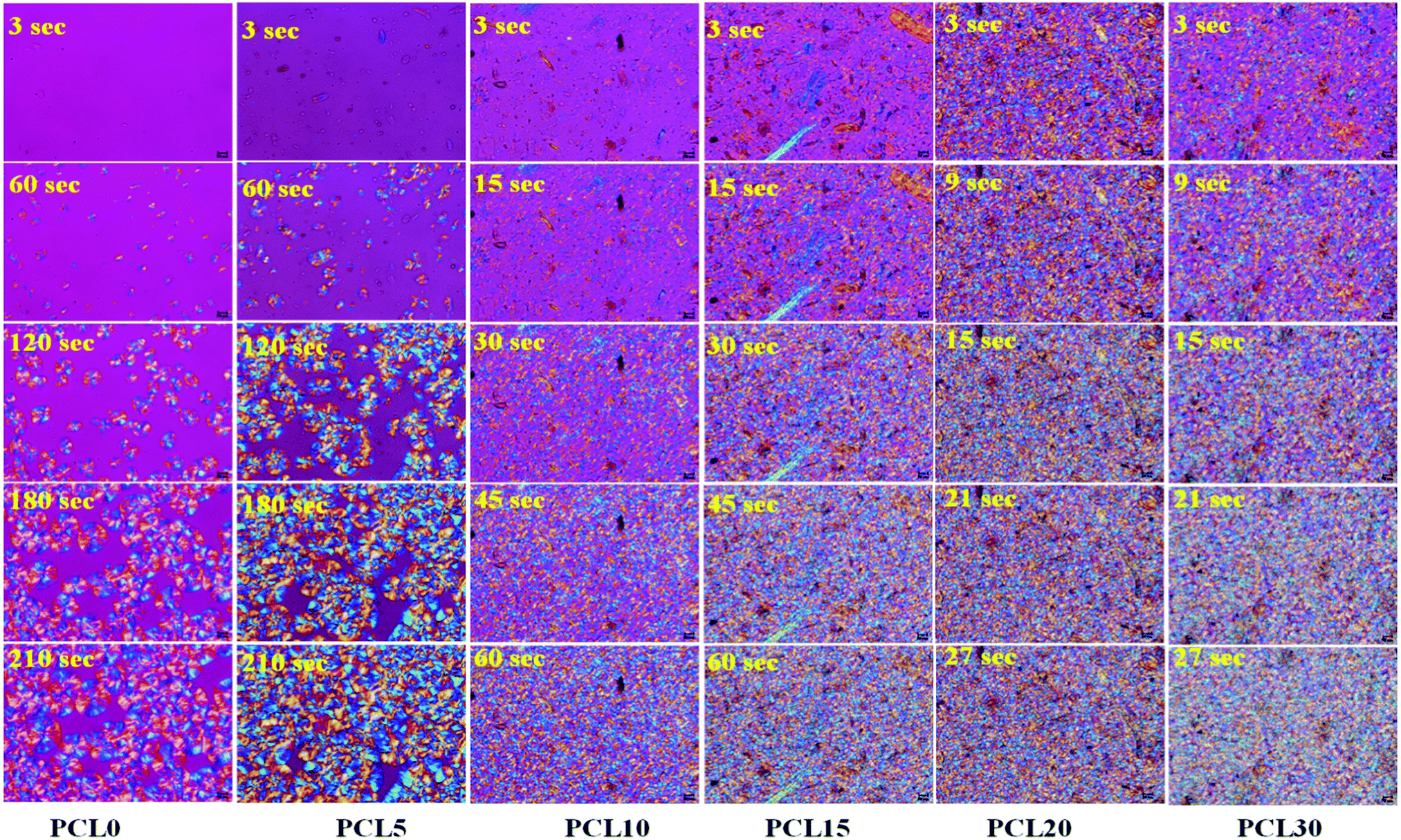 | ||
| Fig. 4 POM micrographs of time-lapse spherulite growth in neat PCL (PCL0) and PCL biocomposites (magnification: 50×). | ||
A comparison of the images, in terms of the nucleation and spherulite growth behaviour with respect to varying time points, helps us to understand the effect of varying the concentration of the bamboo-root flour biofillers on the bulk properties of the PCL matrix. The first image of the samples was taken at a 3 s time point and in this study it is considered as t0, the images were then captured at time intervals of every 3 s. At the 3 s time point, no nucleation was observed in the PCL0 and PCL5 biocomposite samples; whereas, several nucleation points were noticed at the same time point in PCL10, PCL15, PCL20 and PCL30. Although, in PCL10 and PCL15 a reasonably reduced amount of nucleation occurred, there was more nucleation at the vicinity of the filler particles in the case of PCL20 and PCL30. At a high filler concentration, the total number of spherulite initiation sites was dramatically improved, even at the initial time point t0. At the second time point, t60, for PCL0, there were some spherulites that developed from the nucleation stage and at t120 and t180, these continued to grow until they reached the final saturation point, at which the spherical spherulites started to become obstructed by each other's growth (as presented in t210). The low biofiller concentration in PCL5 results in a uniform filler dispersion within the PCL matrix that are well separated from each other, as evident from the images shown in Fig. 4. Furthermore, this result is distinct from the image at the t60 time point in PCL5 indicating that the biofiller particles of varying sizes mostly acted as nucleating agents in PCL during the process of isothermal crystallization. In fact, all biocomposites including PCL5 underwent heterogeneous nucleation initiated by the added biofillers.
As a part of an interesting observation, at the t120 time point, the spherulite size of PCL5 was found to be larger than the spherulites of PCL0, which goes against the common trend. Trans-crystalline morphology was observed across the surfaces of particles with a larger dimension, which essentially kept on growing in size and finally merged to form one superficial spherical shape. As a consequence, there are spherulites with more than one nucleus and the average dimension of the fully grown spherulites in PCL5 were seemingly larger compared to the spherulites observed in PCL0.
To give a better understanding, quantification of the spherulite growth rate and crystal density values of PCL0 and PCL5 were extracted from the plot presented in Fig. 5 and tabulated in Table 3. Although the growth rate of the spherulites was calculated from the slope of the linear fit of the plot spherulite diameter (μm) against time (seconds), the density of the spherulites was estimated using the image processing software Image J®, represented by the number of spherulites per unit area.
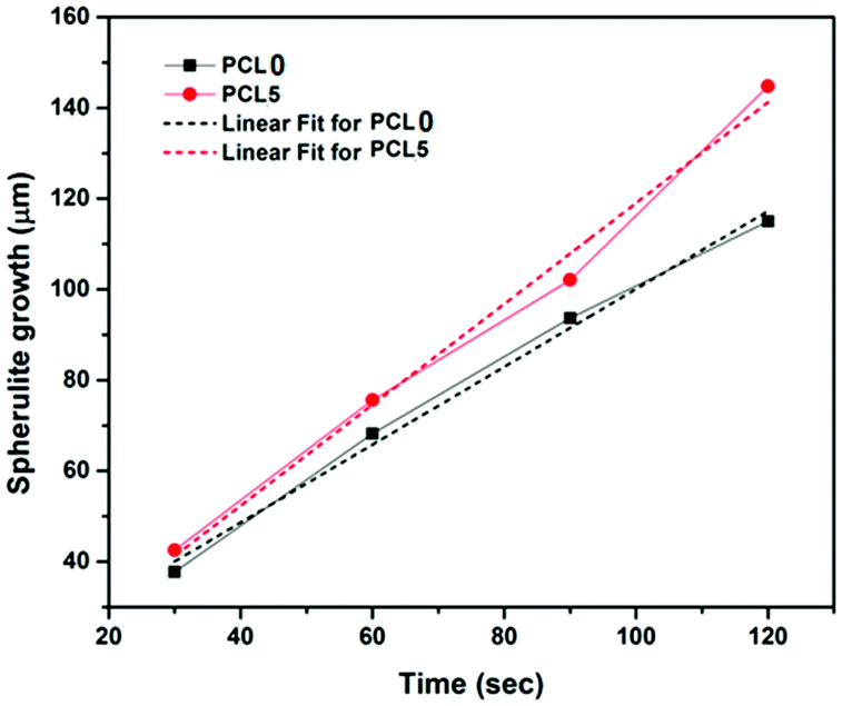 | ||
| Fig. 5 The radial spherulite growth rates of PCL and its biocomposites during melt-crystallization at 120 °C. | ||
| Sample | Spherulite growth-rate (μm s−1) | Spherulite density (number of spherulites per μm2) |
|---|---|---|
| PCL0 | 0.86 | 0.25 |
| PCL5 | 1.11 | 0.46 |
Considering the qualitative representation shown in Fig. 4, a sharp fall in the spherulite sizes was detected in the case of biocomposites with a high filler concentration, for example PCL10 to PCL30, and practically it is impossible to trace individual spherulites. In addition, the nucleating regions in these samples are densely populated with spherulites, which causes a localized rise in the spherulite density. In Table 3, PCL0 has shown a spherulite growth rate of 0.86 μm s−1, whereas an almost two-fold rise in the spherulite growth rate was noticed in PCL5 (∼1.11 μm s−1). The enhanced rate of crystallization in PCL5 led to completion of the isothermal crystallization at a shorter time period relative to PCL0. Obviously, the spherulite density of PCL5 was almost double that of the PCL0. The shooting-up of the spherulite growth rate in PCL10 to PCL30 in comparison to PCL5 can be attributed to the hindrance incurred by the biofiller particles in the growth of the PCL spherulites during the isothermal crystallization process. As a result, the boundaries of the PCL spherulites became unclear in the biocomposites with a higher biofiller concentration and make it difficult to identify or measure individual spherulites in these biocomposites under POM. Nevertheless, it can be clearly understood that the overall rate of crystallization has shown a steep increase, as is obvious from the relative time points in each sample. It is obvious from the information supplied from Fig. 4, as well as Table 3, that there is a clear rise in the spherulite density with an appreciable reduction in the spherulite size upon the addition of bamboo-root flour as a biofiller, which represents an effective nucleation phenomenon.
Reinforced semi-crystalline polymer biocomposites exhibit improved mechanical properties over their neat form. The reinforcement may have a significant impact and alter the polymer crystalline morphology at the interphase regions. In particular, the fibre-like heterogeneous reinforcing phase may act as a nucleating agent and nucleate the crystallization phenomenon at the interphases through developing nuclei density.21 The growth of the crystalline fibrils from these nuclei along the direction perpendicular to the surface of the fibres results in the formation of a columnar crystalline layer, known as the transcrystalline (TC) layer.22 The thickness of this TC layer is limited as the growth proceeds perpendicular to the surface and impinges with the in-growth spherulites nucleated in the bulk of the polymer. Closer observation of the trans-crystallization phenomenon during isothermal crystallization was performed using POM by focusing on PCL5 owing to the low biofiller concentration. The magnified images of the bamboo-root flour biofillers at different locations in PCL5 are presented in Fig. 6.
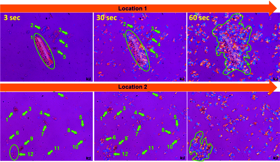 | ||
| Fig. 6 POM micrographs of PCL5 at three different time-points, 3, 30 and 60 s, and at two different locations (magnification: 100×). | ||
Indication of heterogeneous nucleation in the form of trans-crystallization was evident from all the images at the 30 s time-point. Biofillers of different sizes and shapes showed they hosted an identical trans-crystalline region within their interfaces. Larger particles are able to form more nucleation that leads to a higher density at the 60 s time-point, as indicated by the encircled area in location 1 of Fig. 6. The existence of a good polymer–filler interfacial interaction is the cause of the development of the trans-crystallization phenomenon and the resultant reinforcement of the biofillers. As a consequence, PCL5 shows a maximum mechanical reinforcement effect compared to neat PCL. However, at a higher filler concentration, the filler–filler interaction becomes predominant over the polymer–filler interaction. As a result, the reinforcement effect diminishes as the filler agglomeration prevails at a higher concentration in the PCL matrix.
A thorough examination of the fracture morphology of the tensile specimen provides a greater insight into the fracture mechanism of the dumbbell specimens. The nature of the fracture is highly dependent upon the physical and chemical properties of the polymer sample, as well as the yielding that takes place under the influence of tensile stress.23 All samples were tested at a relatively low rate of displacement (5 mm min−1) and at this low displacement rate, neat PCL shows high ductile drawing at its fracture surface. This ductile drawing is related to the viscous flow of polymers under the unidirectional stress that leads to extensive fibrillation. During tensile testing, the samples experience a large degree of one directional tensile stress that involves deformation, giving rise to molecular orientation polymer chains along the axis of the applied stress.
The representative FESEM images of PCL0 at different magnifications are presented in Fig. 7a and a1. Here, we can see the highly ductile morphology of the PCL microfibrils all across the fractured region of the specimen surfaces. Extensive stretching of the oriented polymer chains leads to ductile rupture of the specimen. The highly curled and wavy morphology observed in Fig. 7a1 shows clear evidence of the rupture under plastic flow after crossing the point of yielding. However, a different tensile fracture surface morphology can be seen in the case of PCL5 and the corresponding representative images are presented in Fig. 7b–b4. The spherulite type I structure of PCL has already been discussed in the POM study, in which each spherulite comprises a large number of crystalline lamellae of nanometre dimensions.3 The localized orientation of the polymeric chains involves localized orientation of the spherulites towards the uniaxial tensile direction leading to its distortion and rupture, which is followed by orientation of the constituent lamellae into the fibrillar morphology.20,24 Obviously, in this case a higher stress is required to cause further destruction of such aligned lamellar morphologies.25 As observed in Fig. 7b, a larger region of fibrillar failure, as enclosed by the yellow dotted rectangle of the fractured surface, manifests the PCL5 to exhibit an enhanced ductility. At low magnification, the tensile fracture surface morphology of PCL5 is rough and comprises a large number of pulled and stretched long microfibrils, some of which are indicated by the yellow arrow markings in Fig. 7b. The fibrillation process occurs through extensive plastic deformation of the specimen. Interestingly, these microfibrils are well covered with a particular whitish layer of a substance known as stress-whitening, as observed in Fig. 7b1 and b2. This whitening under stress develops under plastic deformation and is indicated by arrow markings at different locations of the specimen, which need to be examined closely. The formation of stress-whitening indicates massive plastic deformation of the polymer that can be readily explained by the large % EB (1113%) of PCL5 in the tensile stress–strain plot shown in Fig. 3; whereas the absence of stress-whitening represents a brittle fracture.26 Further magnification of these microfibrils reveals a unique morphology. Here, the surfaces of each microfibril consists of a huge number of polymer white nanofibrils that protrude out and are randomly oriented all across the surface. The average diameters of the nanofibrils are calculated using Image J® software and are found within the range of approximately 4–5 nm. These polymer nanofibrils may very possibly be the resultant crystalline fibrils of spherulites that were oriented along the applied stress. These polymer nanofibrils are found to be highly sensitive towards the applied electron beam under FESEM. Evolution of these nanofibers in tensile failure provides evidence for the high UTS and ductility of PCL5. Moreover, the trans-crystallization phenomenon observed under the POM study of the PCL5 sample, as described above, may be correlated with the extensive nanofibrillar morphology of the PCL matrix and the corresponding improvement in mechanical properties. Unlike PCL5, in the case of PCL10; the morphology of the specimen contains crazing followed by tearing of the large microfibrils, see Fig. 7c. The pulled out edges of the large fibrils, as indicated with the yellow markings observed in Fig. 7c were developed through the initiation of craze, subsequent widening and finally breakdown of the fibril morphology, as well as crack propagation along the closely spaced array of the crazes.24 The atomic force microscopy (AFM) analysis of a chlorinated polyethylene (CPE) and PCL blend by Brocorens et al., revealed that highly crystalline PCL was observed to be distributed within a chlorinated polyethylene (CPE) matrix in the form of needle shaped, striped bundles of lamella with a thickness ranging 9–13 nm.27 Along similar lines, instead of a fine, nanofibrillar morphology, bundles of needle-like lamella with a thickness within the range of 8–15 nm were observed in multiple locations as the encircled area on the fractured surfaces of PCL10 in Fig. 7c.28 Large bunches of PCL lamellas are disoriented along different directions. Several individual lamellae can also be found that were projected out of the examined surface. These needle-like crystalline lamella of PCL are also visible within the structure, partially retaining its integrity in spherulites as shown with the encircled region of Fig. 7c1. This needle-like morphology of the PCL crystals in the biocomposite could partly be responsible for the important changes in the mechanical properties of PCL10, in particular to the improvement in the Young's modulus in comparison to PCL0.27 Fusion of ductile, as well as brittle failure, can readily be observed in the tensile fracture surface of PCL15 in Fig. 7d. Although a fibrillar morphology with larger dimensions was observed in Fig. 7d1, wherein magnifying the indicated location in Fig. 7d2 did not show the presence of any nanofibrils. However, dramatic changes in the behaviour of the tensile fracture morphology of PCL20 and PCL30 from all other samples was observed in Fig. 7e–e2 and f–f2, respectively. The occurrence of a ductile-to-brittle transition in PCL20 and PCL30 can be predicted through the changes in the tensile fracture topography from a rough, fibrous nature to a flat and relatively smoother surface.26 Across the entire sample surface, a comprehensive brittle fracture morphology can be observed from the magnified images as well. In the particular case of PCL30, the relatively smoother fracture surface, along with river patterns and regional fracture roughness owing to the propagation of cracks is initiated by the void developed by the excess quantity of biofiller particles.29,30 This overall discussion implies that varying the concentration of the reinforcing biofiller has a significant impact on the fracture surface morphology of the PCL biocomposites. The mechanical behaviour of the biocomposites was found to be reciprocated in parallel to the above investigative discussion on the tensile fracture surface morphology.
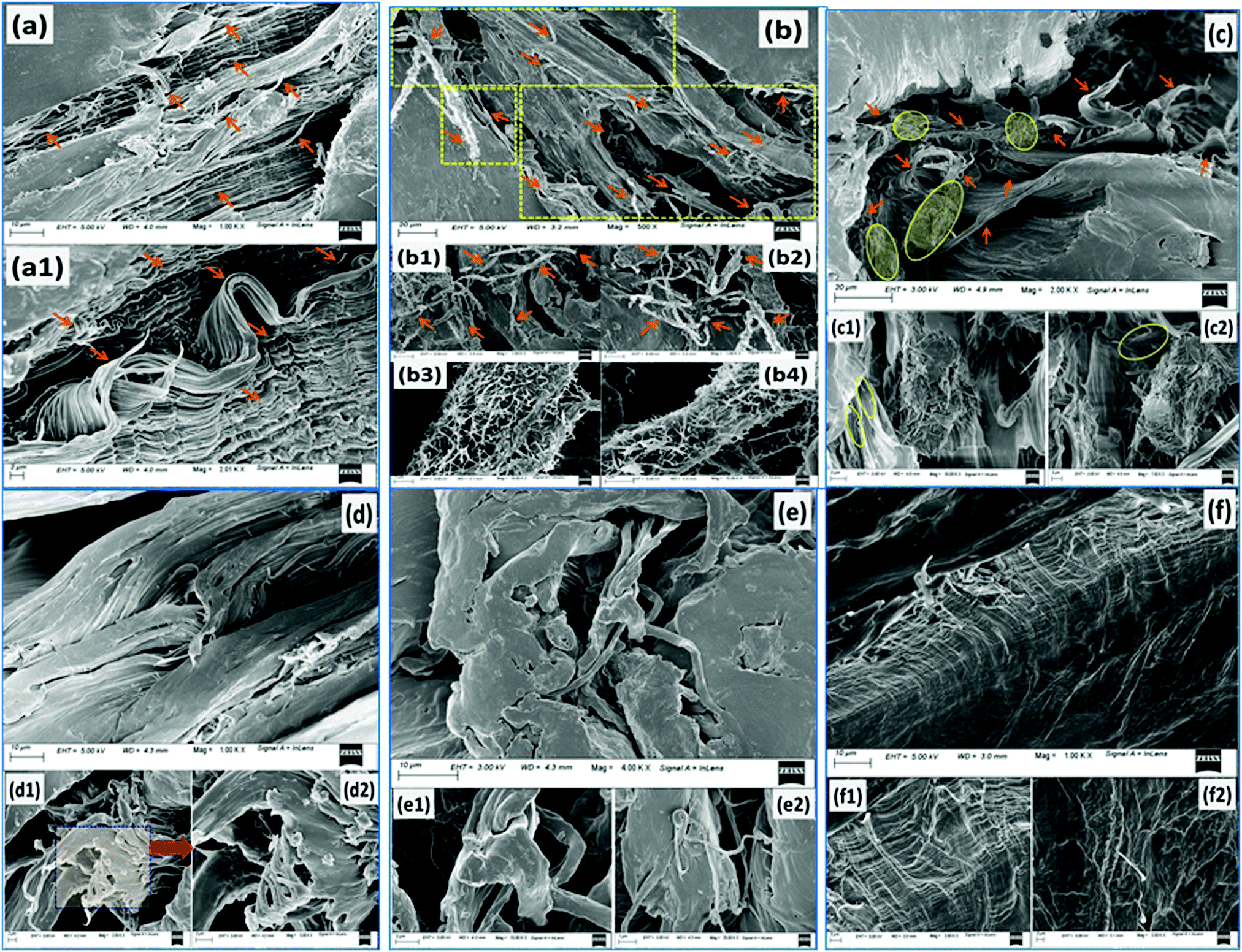 | ||
| Fig. 7 Representative FESEM images of the tensile fractured surfaces of different PCL based samples: (a)–(a1) PCL0; (b)–(b4) PCL5; (c)–(c2) PCL10; (d)–(d2) PCL15; (e)–(e2) PCL20; and (f)–(f2) PCL30. | ||
3.3. Studies of the crystallization characteristics
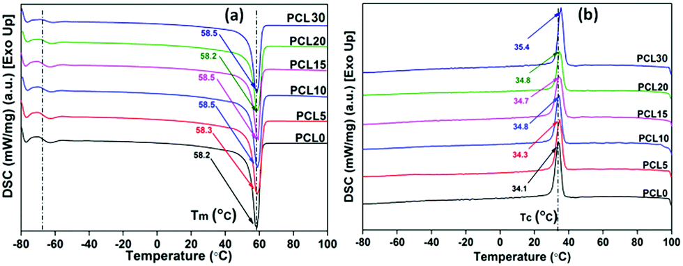 | ||
| Fig. 8 Representative (a) second heating and (b) first cooling thermograms of melt processed neat PCL and its bamboo-root flour biocomposites. | ||
| Sample designation | T g (°C) | ΔCp (J g−1 °C−1) | T m (°C) | T c (°C) | ΔHm (J g−1) | ΔHc (J g−1) | % crystallinity (% Xc) |
|---|---|---|---|---|---|---|---|
| a All data are taken from averages of three samples and the error limits are within ±2%. | |||||||
| PCL0 | −66.1 | 0.97 | 58.3 | 34.1 | 65.4 | 69.3 | 45.7 |
| PCL5 | −66.2 | 0.64 | 58.5 | 34.6 | 60.7 | 63.9 | 42.4 |
| PCL10 | −66.2 | 0.78 | 58.5 | 34.8 | 55.8 | 62.2 | 39.0 |
| PCL15 | −65.9 | 0.51 | 58.5 | 34.7 | 46.8 | 65.6 | 32.7 |
| PCL20 | −66.0 | 0.60 | 58.2 | 34.8 | 47.3 | 48.7 | 33.0 |
| PCL30 | −65.8 | 0.35 | 58.5 | 35.4 | 49.5 | 67.8 | 34.6 |
There is little to no significant change in the Tg of the PCL biocomposites from the control sample and all samples were found to have a Tg value within the range of −66.0 ± 0.3 °C. Although investigation into the mechanical properties refers to the reinforcing effect of the bamboo-root flour in the PCL matrix, the absence of any strong chemical interaction, such as covalent bond formation or ionic interactions, might be the possible reason for the unaltered Tg at temperatures as low as −66.0 °C in the biocomposites, in comparison to neat PCL. As expected, the heat capacity difference between the glassy state and liquid state of the PCL biocomposites was reduced compared to neat PCL. Neat PCL has poor intermolecular interactions; whereas, the PCL biocomposite possesses a stronger secondary force of interaction owing to the presence of bamboo-root flour. These biofillers are capable of developing mechanical interlocking of polymer chains with the bamboo-root particles.
There is no significant change in the Tm of the biocomposites from neat PCL and this may be related to the mechanical reinforcement of the PCL matrix with the biofillers. However, the crystallization temperatures (Tc) of the composites are slightly higher than the Tc of neat PCL. The increased Tc of the biocomposites over neat PCL can be related to the heterogeneous nucleation of the biofillers that hasten the crystallization phenomenon in the PCL matrix during the cooling cycle. The increased rate of crystallization in the biocomposites may cause an appreciable rise in the Tc in comparison to neat PCL. The increased Tc of the PCL biocomposites could be the result of the improved degree of crystallinity or polymer–filler interfacial interactions.22,31 However, from Table 4, it can be understood that there is a decrease in the % crystallinity (% Xc) and the crystallization enthalpy in the biocomposites upon increasing the content of biofillers in PCL. Among the biocomposites, PCL5 shows the highest % Xc and the value shows a decreasing trend as the biofiller concentration increases. It is noteworthy to mention that the reduced % Xc in PCL 10-PCL 30 may not be related to the POM data because of the high nucleation density, making error free calculation of the spherulite growth rate practically impossible.
The presence of a large amount of biofillers in the PCL matrix reduces the polymer chain mobility, thereby reducing the possibility for polymer chain orientation to develop a highly ordered crystalline region.32 This indicates the preferable effect of the interfacial interaction between the PCL matrix and the biofillers upon the mechanical properties of the biocomposites. The existence of a good polymer–filler interaction in the biocomposites is also suggested by the increased Tc values of the biocomposites over neat PCL. The increased Tc is associated with the increased density of nuclei for crystallization and also comprises characteristics such as smaller grain boundaries.33,34 Mechanical reinforcement of the PCL matrix by the added biofillers through polymer–filler interfacial adhesion may act as a contributing factor in maintaining the Tm of the biocomposites with neat PCL. In other words, the thermal characteristics of the biocomposites can be interpreted by its crystal formation behaviour, which in turn is also dependent upon the polymer–filler interfacial adhesion in biocomposites.
The insignificant alteration of Tm and the visibly clear increase in the Tc of the biocomposites over neat PCL, as obviously shown from the DSC thermograms, represents a certain degree of consistency in the phase change temperature (Tm − Tc) values in all samples, as shown in Fig. 9. The heterogeneous nucleating effect of the biofillers in the PCL polymer matrix prompts the crystallization phenomenon and reduces the crystallite granule boundary size, which reportedly minimizes the degree of supercooling in the biocomposites.35,36 The data corresponding to crystallinity obtained from the DSC analysis of the samples were cross verified with X-ray diffraction studies of the samples.
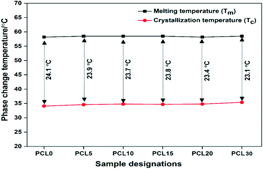 | ||
| Fig. 9 The phase change temperatures (Tm and Tc) and the degree of supercooling of neat PCL (PCL0) and its biocomposites with bamboo-root flour. | ||
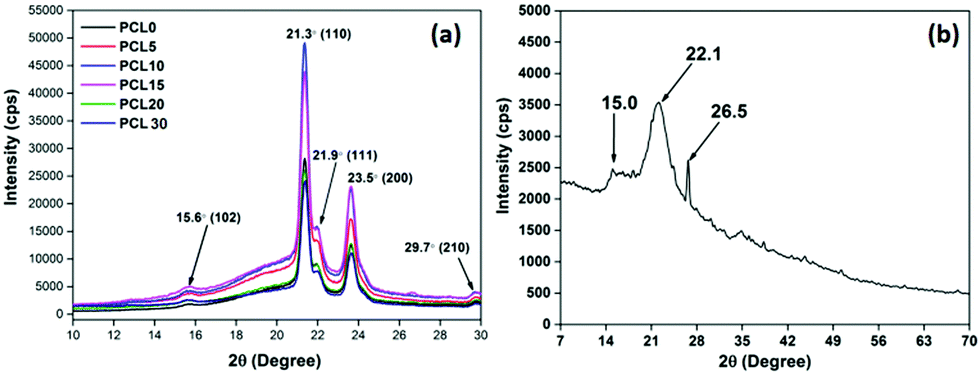 | ||
| Fig. 10 Representative XRD patterns of (a) neat PCL and its biocomposites with bamboo-root flour and (b) the biofiller bamboo-root flour. | ||
The XRD diffractogram of neat PCL is characterized by two broad peaks at 21.3°–21.9° and 23.5° that correspond to the (110), (111) and (200) crystallographic planes, respectively.3 Two peaks with less significance can also be observed at 15.6° and 29.7° that correspond to the (102) and (210) diffraction planes of PCL.44 PCL is a semi-crystalline polymer and the peaks observed in the XRD patterns are located over a much wider and dispersed amorphous halo.45 The presence of bamboo-root flour in the PCL matrix shows no trace of the biofiller identity in the XRD diffraction pattern. All of the characteristic peaks of the biofillers were submerged within the PCL matrix. The presence of the biofillers incorporates a higher degree of amorphous phase in the biocomposites, which is evident from the increased area of the amorphous halo. A concentration of bamboo-root flour over the range of 5–10 wt% essentially increased the overall peak intensities.
This is followed by a fall in the trend as the biofiller loading concentration was higher than 10 wt% and keeps on increasing up to 30 wt%. Deconvolution of the peaks using XpertHighscore® software enabled the effect of the biofiller loading concentration upon the crystalline behaviour of the PCL biocomposites to be understood. Data extracted from the XRD patterns of all samples are presented in Table 5, from which it is apparent that the percentage degree of crystallinity (% Xc) of the biocomposites is less than that of PCL0. Similar trends in the values are also observed from the DSC analysis of the samples. The ability of the biofillers to act as a nucleating agent at a low concentration of biofiller can be manifested from the POM images. In addition, the morphology analysis through FESEM of PCL5–PCL10 shows a high ductile fracture along with a large number of crystalline fibrils. This suggests the enhanced value of the overall degree of crystallinity in the PCL5–PCL10 biocomposites. However, at a higher concentration of the biofillers, at 15–30 wt%, the degree of crystallinity reduced significantly. A similar trend was reported elsewhere and the phenomenon was explained with two contradictory effects of nucleation, which are not always obvious, and the reinforcement induced anti-plasticization effect.46,47 At a relatively low filler concentration, such as 5 wt% and 10 wt%, owing to the heterogeneous nucleation effect, there is a rise in the degree of crystallinity upon increasing the rate of crystallization in PCL5 and PCL10. On the other hand, the PCL chain movements are restricted by the reinforcing effect of the biofillers and this limits its ability to arrange itself into a regular pattern. At a higher concentration of the biofillers in PCL, the later mentioned effect predominates and subsequently reduces the degree of crystallinity in the PCL biocomposites.
| Sample designation | % crystallinity (% Xc) |
|---|---|
| PCL0 | 52.3 |
| PCL5 | 51.1 |
| PCL10 | 50.4 |
| PCL15 | 43.0 |
| PCL20 | 41.3 |
| PCL30 | 42.0 |
4. Conclusions
In the present work, cost-effective bamboo-root-flour-filled biodegradable poly(ε-caprolactone) [PCL] based biocomposites with enhanced physico-mechanical properties were developed through a conventional melt mixing technique. The simple and raw process technology for the preparation of bamboo-root flour and the corresponding cumulative effect on the mechanical, as well as other physical properties, shows the originality of the work. The PCL biocomposites were studied to determine the effect of the bamboo-root filler on the tensile properties, as well as the crystalline characteristics. It was shown that the biofiller loading had a significant impact on these two characteristics of the PCL biocomposites, as evidenced by the experimental results. The mechanical performances of PCL0, PCL5, and PCL10 are superior compared to neat LLDPE, as the percentage improvements in the UTS, the % EB and the tensile toughness of PCL0 (91.2%, 102%, and 206%), PCL5 (148%, 166%, and 379%) and PCL10 (78%, 84%, and 177%) were very high. The biocomposite with a maximum biofiller loading of 30 wt% showed a UTS of 12.4 MPa and a % EB of 243%, which were comparable to the values obtained for LLDPE. Furthermore, the higher modulus of PCL30 over LLDPE may help to improve the mechanical load bearing capacity of the biocomposite. The concept of the effective reinforcement that biofillers provide to the PCL matrix was sustained by studying the crystalline morphology, as well as the tensile fracture surface of the biocomposites, using POM and FESEM. The trans-crystallization phenomenon induced by the biofillers and the large amount of nanofibrils observed on the tensile fractured surfaces of the biocomposites support the claims based on the mechanical data. Although the cost of biodegradable PCL is higher than that of commercial LLDPE, from the overall discussion it can be realized that the inclusion of cheap biowaste, such as bamboo-root powder, at high concentrations as a filler in PCL would effectively address this issue at the expense of the mechanical performance within an acceptable range. Our work demonstrates the development of a cost-effective, biodegradable alternative to commercially existing LLDPE, which provides a novel dimension for the study of materials for possible flexible cryo-packaging applications.Conflicts of interest
There are no conflicts to declare.Acknowledgements
The authors would like to recognize the research grant ‘National Post-doctoral Fellowship (NPDF)’ received from the Science and Engineering Research Board (SERB), Department of Science and Technology (DST), India (PDF/2016/003412/CS). The authors also sincerely thank the Department of Chemicals & Petrochemicals, Ministry of Chemicals and Fertilizers, Government of India – funded Centre of Excellence for Sustainable Polymers at IIT Guwahati for the research facilities used to perform this current research work.References
- E. Chiellini, P. Cinelli, F. Chiellini and S. H. Imam, Macromol. Biosci., 2004, 4, 218–231 CrossRef CAS.
- N. K. Kalita, S. M. Bhasney, C. Mudenur, A. Kalamdhad and V. Katiyar, Chemosphere, 2020, 247, 125875 CrossRef CAS.
- P. Bhagabati, D. Hazarika and V. Katiyar, Int. J. Biol. Macromol., 2019, 124, 1040–1052 CrossRef CAS.
- R. M. d. Andrade, S. M. d. Silva Júnior, S. V. C. R. Coutinho, N. G. Jaques, H. d. V. Pina, B. G. Rodrigues, M. V. L. Fook, P. C. R. Fernandes, A. Ries and R. M. R. Wellen, Matéria, 2018, 23, e12255 Search PubMed.
- F. Yahiaoui, F. Benhacine, H. Ferfera-Harrar, A. Habi, A. S. Hadj-Hamou and Y. Grohens, Polym. Bull., 2015, 72, 235–254 CrossRef CAS.
- J. S. Lyu, J.-S. Lee and J. Han, Sci. Rep., 2019, 9, 1–11 CrossRef.
- S.-i. Akahori and Z. Osawa, Polym. Degrad. Stab., 1994, 45, 261–265 CrossRef CAS.
- L. J. Ronald Sabo, N. Stark and R. E. Ibach, BioResources, 2013, 8, 13 Search PubMed.
- Y. K. T. Kanisha Jha and A. Singh Yadav, Sadhana, 2018, 43, 5 CrossRef.
- H. Wang, M. Kabir, T. Aravinthan, F. Cardona and K. T. Lau, eddBE Proceedings, 2011, p. 5 CAS.
- F. Vilaplana, E. Strömberg and S. Karlsson, Polym. Degrad. Stab., 2010, 95, 2147–2161 CrossRef CAS.
- K. Kitagawa, U. Ishiaku, M. A. Mizoguchi and H. Hamada, Natural fibers, biopolymers, and biocomposites, CRC Press, Boca Raton, 2005 Search PubMed.
- S. Amada, Y. Ichikawa, T. Munekata, Y. Nagase and H. Shimizu, Composites, Part B, 1997, 28, 13–20 CrossRef.
- U. Jindal, J. Compos. Mater., 1986, 20, 19–29 CrossRef CAS.
- S. G. Kamol Dey, R. A. Khan and M. A. Khan, J. Compos. Biodegrad. Polym., 2013, 1, 7 Search PubMed.
- I. M. Ward and J. Sweeney, Mechanical properties of solid polymers, John Wiley & Sons, 2012 Search PubMed.
- H. Brinson and A. DasGupta, Exp. Mech., 1975, 15, 458–463 CrossRef.
- K.-H. Nitta and N. Yamaguchi, Polym. J., 2006, 38, 122–131 CrossRef CAS.
- K.-H. Nitta, Comput. Theor. Polym. Sci., 1999, 9, 19–26 CrossRef CAS.
- C. De Rosa and F. Auriemma, Crystals and crystallinity in polymers: diffraction analysis of ordered and disordered crystals, John Wiley & Sons, 2013 Search PubMed.
- Y. Wang, B. Tong, S. Hou, M. Li and C. Shen, Composites, Part A, 2011, 42, 66–74 CrossRef.
- T. McNally, P. Pötschke, P. Halley, M. Murphy, D. Martin, S. E. Bell, G. P. Brennan, D. Bein, P. Lemoine and J. P. Quinn, Polymer, 2005, 46, 8222–8232 CrossRef CAS.
- P. A. Lovell, Trends Polym. Sci., 1996, 8, 264–272 Search PubMed.
- A. Dasari, S. Duncan and R. Misra, Mater. Sci. Technol., 2002, 18, 685–690 CrossRef CAS.
- J. M. Lagarón, G. Capaccio, L. J. Rose and B. J. Kip, J. Appl. Polym. Sci., 2000, 77, 283–296 CrossRef.
- J. C. M. Suarez and R. S. de Biasi, Polym. Degrad. Stab., 2003, 82, 221–227 CrossRef CAS.
- P. Brocorens, S. Benali, C. Broekaert, F. Monteverde, H. E. Miltner, B. Van Mele, M. Alexandre, P. Dubois and R. Lazzaroni, Langmuir, 2008, 24, 2072–2080 CrossRef CAS.
- S. Hocquet, A. Draye, M. Dosiere and M. Koch, HASYLAB Annual Report 2001, Part II, 2001.
- C. Chen, C. Zhang, C. Liu, Y. Miao, S.-C. Wong and Y. Li, Composites, Part B, 2018, 136, 187–196 CrossRef CAS.
- P. Guoliang, G. Qiang, T. Aiguo and H. Zhiqiang, Mater. Sci. Eng., A, 2008, 492, 383–391 CrossRef.
- M. El Achaby, F. E. Arrakhiz, S. Vaudreuil, A. el Kacem Qaiss, M. Bousmina and O. Fassi-Fehri, Polym. Compos., 2012, 33, 733–744 CrossRef CAS.
- K. Lozano and E. Barrera, J. Appl. Polym. Sci., 2001, 79, 125–133 CrossRef CAS.
- A. P. Mathew, K. Oksman and M. Sain, J. Appl. Polym. Sci., 2006, 101, 300–310 CrossRef CAS.
- M. N. Angles and A. Dufresne, Macromolecules, 2000, 33, 8344–8353 CrossRef.
- L. Xia and P. Zhang, Sol. Energy Mater. Sol. Cells, 2011, 95, 2246–2254 CrossRef CAS.
- L. Zhang, J. Zhu, W. Zhou, J. Wang and Y. Wang, Energy, 2012, 39, 294–302 CrossRef CAS.
- C. Jin, J. Li, S. Han, J. Wang and Q. Sun, Appl. Surf. Sci., 2014, 320, 322–327 CrossRef CAS.
- M. A. Esmeraldo, A. C. Gomes, J. E. Freitas, P. B. Fechine, A. S. Sombra, E. Corradini, G. Mele, A. Maffezzoli and S. E. Mazzetto, BioResources, 2010, 5, 2478–2501 Search PubMed.
- J. Li, Y. Lu, D. Yang, Q. Sun, Y. Liu and H. Zhao, Biomacromolecules, 2011, 12, 1860–1867 CrossRef CAS.
- E. Abraham, P. Elbi, B. Deepa, P. Jyotishkumar, L. Pothen, S. Narine and S. Thomas, Polym. Degrad. Stab., 2012, 97, 2378–2387 CrossRef CAS.
- Y. Nishiyama, P. Langan and H. Chanzy, J. Am. Chem. Soc., 2002, 124, 9074–9082 CrossRef CAS.
- Y. Li, L. Jiang, C. Xiong and W. Peng, Ind. Eng. Chem. Res., 2015, 54, 12017–12024 CrossRef CAS.
- Y. Guan, B. Zhang, X.-M. Qi, F. Peng, C.-L. Yao and R.-C. Sun, Carbohydr. Polym., 2015, 129, 201–207 CrossRef CAS.
- F. Tuba, L. Olah and P. Nagy, eXPRESS Polym. Lett., 2014, 8, 869–879 CrossRef.
- C. Guang-Mei, Z. Tie-Mei, C. Lei and H. Yi-Ping, Asian J. Chem., 2010, 22, 5902 Search PubMed.
- J. Z. Liang, L. Zhou, C. Y. Tang and C. P. Tsui, J. Appl. Polym. Sci., 2013, 128, 2940–2944 CrossRef CAS.
- R. Gogoi, N. Kumar, S. Mireja, S. S. Ravindranath, G. Manik and S. Sinha, JOM, 2019, 71(2), 548–558 CrossRef CAS.
Footnote |
| † Electronic supplementary information (ESI) available. See DOI: 10.1039/d0ma00517g |
| This journal is © The Royal Society of Chemistry 2021 |